

Page 1

Guardmaster® 440G-LZ Guard Locking Switch
User Manual
Page 2
Important User Information
IMPORTANT
Solid-state equipment has operational characteristics differing from those of electromechanical equipment.
Safety Guidelines for the Application, Installation and Maintenance of Solid State Controls (publication
SGI-IN001_-EN-P
http://www.rockwellautomation.com/literature/
equipment and hard-wired electromechanical devices. Because of this difference, and also because of the wide
variety of uses for solid-state equipment, all persons responsible for applying this equipment must satisfy
themselves that each intended application of this equipment is acceptable.
In no event will Rockwell Automation, Inc. be responsible or liable for indirect or consequential damages
resulting from the use or application of this equipment.
The examples and diagrams in this manual are included solely for illustrative purposes. Because of the many
variables and requirements associated with any particular installation, Rockwell Automation, Inc. cannot
assume responsibility or liability for actual use based on the examples and diagrams.
No patent liability is assumed by Rockwell Automation, Inc. with respect to use of information, circuits,
equipment, or software described in this manual.
Reproduction of the contents of this manual, in whole or in part, without written permission of Rockwell
Automation, Inc., is prohibited.
available from your local Rockwell Automation sales office or online at
) describes some important differences between solid-state
Throughout this manual, when necessary, we use notes to make you aware of safety considerations.
WARNING: Identifies information about practices or circumstances that can cause an explosion in a hazardous environment,
which may lead to personal injury or death, property damage, or economic loss.
ATTENTION: Identifies information about practices or circumstances that can lead to personal injury or death, property
damage, or economic loss. Attentions help you identify a hazard, avoid a hazard, and recognize the consequence.
SHOCK HAZARD: Labels may be on or inside the equipment, for example, a drive or motor, to alert people that dangerous
voltage may be present.
BURN HAZARD: Labels may be on or inside the equipment, for example, a drive or motor, to alert people that surfaces may
reach dangerous temperatures.
Identifies information that is critical for successful application and understanding of the product.
It is recommended that you save this user manual for future use.
2 Rockwell Automation Publication 440G-UM001A-EN-P — November 2013
Page 3

Read this preface to become familiar with the rest of the manual.
It provides information concerning:
• who should use this manual
• the purpose of this manual
• related documentation
• conventions used in this manual
Preface
Who Should Use This Manual
Purpose of This Manual
Conventions Used in This
Manual
Use this manual if you are responsible for designing, installing,
programming, or troubleshooting systems that use the Guardmaster
440G-LZ guard locking switch.
You should have a basic understanding of electrical circuitry and
familiarity with safety-related systems. If you do not, obtain the proper
training before using this product.
This manual is a reference guide for the Guardmaster 440G-LZ guard
locking switch. It describes the procedures you use to install, wire, and
troubleshoot your switch. This manual:
• Explains how to install and wire your 440G-LZ
• Provides an overview of the Guardmaster 440G-LZ guard locking
switch
The following conventions are used throughout this manual:
• Bulleted lists such as this one provide information, not procedural
steps.
• Numbered lists provide sequential steps or hierarchical
information.
Additional Resources
The following document offers additional information about related
Rockwell Automation products:
Resource Description
Allen-Bradley Industrial Automation Glossary,
publication AG-7.1
Rockwell Automation Publication 440G-UM001A-EN-P — November 2013 3
Glossary of industrial automation terms and
abbreviations
Page 4

Preface
Terminology
You can view and download publications at http://
www.rockwellautomation.com/literature/ . To order paper copies of
technical documents, contact your local Rockwell Automation distributor
or sales representative.
OSSD Output Signal Switching Device. Typically designates a pair of solid state
signals pulled up to the DC source supply. The signals are usually tested for
short circuits to the DC power supply, short circuits to the DC common, and
short circuits between the two signals.
Standard coding Same as Low coding as defined in EN/ISO 14119:2013
Unique coding Same as High coding as defined in EN/ISO 14119:2013
4 Rockwell Automation Publication 440G-UM001A-EN-P — November 2013
Page 5

General Description
Safety Concept
Table of Contents
Important User Information . . . . . . . . . . . . . . . . . . . . . . . . . . . . . . . . . . . . 2
Preface
Who Should Use This Manual. . . . . . . . . . . . . . . . . . . . . . . . . . . . . . . . . . . 3
Purpose of This Manual . . . . . . . . . . . . . . . . . . . . . . . . . . . . . . . . . . . . . . . . 3
Conventions Used in This Manual. . . . . . . . . . . . . . . . . . . . . . . . . . . . . . . 3
Additional Resources. . . . . . . . . . . . . . . . . . . . . . . . . . . . . . . . . . . . . . . . . . . 3
Terminology . . . . . . . . . . . . . . . . . . . . . . . . . . . . . . . . . . . . . . . . . . . . . . . . . . . 4
Chapter 1
Guardmaster 440G-LZ Overview. . . . . . . . . . . . . . . . . . . . . . . . . . . . . . . . 7
Assembly Overview . . . . . . . . . . . . . . . . . . . . . . . . . . . . . . . . . . . . . . . . . . . . 8
Packaging Contents. . . . . . . . . . . . . . . . . . . . . . . . . . . . . . . . . . . . . . . . . . . . 8
Chapter 2
Safety Standards Applied to Guardmaster 440G-LZ. . . . . . . . . . . . . 11
Introduction . . . . . . . . . . . . . . . . . . . . . . . . . . . . . . . . . . . . . . . . . . . . . . . . . . 11
Safety Certification . . . . . . . . . . . . . . . . . . . . . . . . . . . . . . . . . . . . . . . . . . . . 11
Installation and Wiring
Description of Operation
Chapter 3
General Considerations . . . . . . . . . . . . . . . . . . . . . . . . . . . . . . . . . . . . . . . 13
Pair Proximity . . . . . . . . . . . . . . . . . . . . . . . . . . . . . . . . . . . . . . . . . . . . . . . . . 13
Orientation of Switches . . . . . . . . . . . . . . . . . . . . . . . . . . . . . . . . . . . . . . . 14
Setting the Actuator Direction of Approach . . . . . . . . . . . . . . . . . . . . 15
Mounting the Assembled Actuator . . . . . . . . . . . . . . . . . . . . . . . . . . . . 16
Mounting the Switch Body . . . . . . . . . . . . . . . . . . . . . . . . . . . . . . . . . . . . 17
Setting Actuator to Switch Alignment . . . . . . . . . . . . . . . . . . . . . . . . . 17
Actuator RFID Setting . . . . . . . . . . . . . . . . . . . . . . . . . . . . . . . . . . . . . . . . . 18
LED Error Codes During the Learning Process . . . . . . . . . . . . . . . . . . 19
Proving Basic Lock Function . . . . . . . . . . . . . . . . . . . . . . . . . . . . . . . . . . . 20
Wiring . . . . . . . . . . . . . . . . . . . . . . . . . . . . . . . . . . . . . . . . . . . . . . . . . . . . . . . . 21
Connection Systems . . . . . . . . . . . . . . . . . . . . . . . . . . . . . . . . . . . . . . . . . . 21
Chapter 4
Description of LEDs During Operation . . . . . . . . . . . . . . . . . . . . . . . . . 23
Status/Diagnostic LED During Troubleshooting . . . . . . . . . . . . . . . . 24
Auxiliary Out Function . . . . . . . . . . . . . . . . . . . . . . . . . . . . . . . . . . . . . . . . 24
Guardmaster 440G-LZ Wiring with GSR Relay . . . . . . . . . . . . . . . . . . 25
Guardmaster 440G-LZ Wiring with Point I/O . . . . . . . . . . . . . . . . . . . 26
Guardmaster 440G-LZ Wiring with GLP Relay . . . . . . . . . . . . . . . . . . 26
Guardmaster 440G-LZ Troubleshooting Series Circuit . . . . . . . . . . 27
Unit Response Times . . . . . . . . . . . . . . . . . . . . . . . . . . . . . . . . . . . . . . . . . . 27
OSSD Output Test Pulses . . . . . . . . . . . . . . . . . . . . . . . . . . . . . . . . . . . . . . 28
Auxiliary/Manual Release. . . . . . . . . . . . . . . . . . . . . . . . . . . . . . . . . . . . . . 28
Rockwell Automation Publication 440G-UM001A-EN-P — November 2013 5
Page 6

Table of Contents
Appendix A
Specifications
Typical Installations
Introduction . . . . . . . . . . . . . . . . . . . . . . . . . . . . . . . . . . . . . . . . . . . . . . . . . . 29
Safety Ratings . . . . . . . . . . . . . . . . . . . . . . . . . . . . . . . . . . . . . . . . . . . . . . . . . 29
Operating Characteristics. . . . . . . . . . . . . . . . . . . . . . . . . . . . . . . . . . . . . . 29
Outputs. . . . . . . . . . . . . . . . . . . . . . . . . . . . . . . . . . . . . . . . . . . . . . . . . . . . . . . 30
Environmental and General Protection. . . . . . . . . . . . . . . . . . . . . . . . . 31
Certifications. . . . . . . . . . . . . . . . . . . . . . . . . . . . . . . . . . . . . . . . . . . . . . . . . . 31
Compliance to European Union Directives . . . . . . . . . . . . . . . . . . . . . 32
Overall Dimensions. . . . . . . . . . . . . . . . . . . . . . . . . . . . . . . . . . . . . . . . . . . . 32
Catalog Numbers. . . . . . . . . . . . . . . . . . . . . . . . . . . . . . . . . . . . . . . . . . . . . . 34
Appendix B
Switch Mounted Parallel to Hinge Axis . . . . . . . . . . . . . . . . . . . . . . . . . 35
Switch Mounted Perpendicular to Hinge Axis . . . . . . . . . . . . . . . . . . 36
Switch Mounted to a Sliding Guard . . . . . . . . . . . . . . . . . . . . . . . . . . . . 36
EU Declaration of Conformity . . . . . . . . . . . . . . . . . . . . . . . . . . . . . . . . . . 37
6 Rockwell Automation Publication 440G-UM001A-EN-P — November 2013
Page 7

General Description
Chapter 1
Guardmaster 440G-LZ
Overview
This Guardmaster 440G-LZ guard locking switch functions by extending a
locking bolt from the switch through a hole in the actuator, thus
preventing the opening of a guard.
The locking bolt drive mechanism and logic ensure that the locking bolt
is allowed to extend only when the corresponding actuator is detected
within range.
The appropriate actuator is detected by RFID coding.
This version of the Guardmaster 440G-LC guard locking switch features
OSSD outputs that are enabled only when the locking bolt is sensed in its
extended position in the actuator, which happens only when the guard is
both closed and locked.
The locking bolt drive mechanism uses a bi-stable solenoid; as a result,
the switch consumes very little electrical power, with peak currents
occurring only briefly, upon start-up and after each movement of the
locking bolt.
Because of its bi-stable drive, not only does the device consume minimal
power, but it does not produce heat whether in its locked or unlocked
condition.
Despite the bi-stable design of the locking bolt drive, the device logic and
functionality are configured to replicate the functionality of a power-torelease or power-to-lock solenoid-operated switch (depending on type).
Rockwell Automation Publication 440G-UM001A-EN-P — November 2013 7
Page 8
Chapter 1 General Description
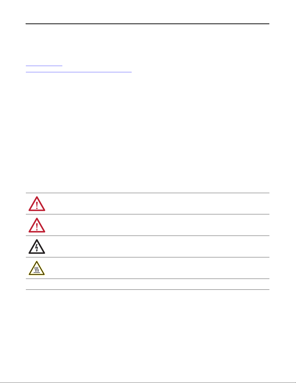
Locking bolt
Act uato r
Switch body
Actu ator
mounting bracket
QR Code
Alignment guide
Guardmaster 440G-LZ
Assembly Overview
Packaging Contents
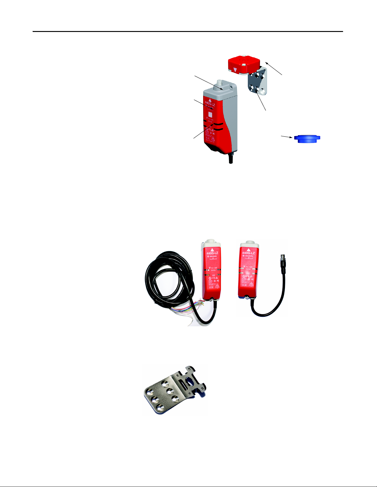
The box includes the following components:
Switch body including connection lead: 3 m or 10 m flying lead or
pigtail equipped with M12 QD connector
Actuator mounting bracket
8 Rockwell Automation Publication 440G-UM001A-EN-P — November 2013
Page 9
General Description Chapter 1
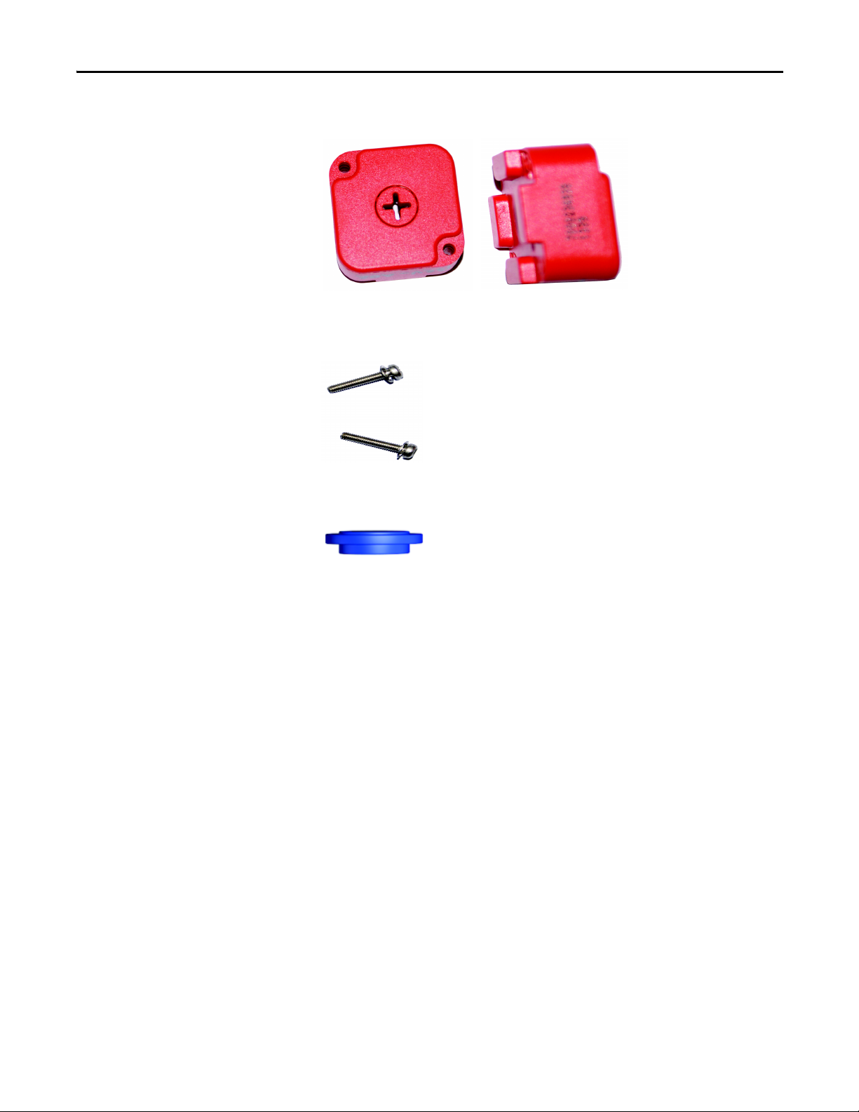
Actuator
Actuator-to-actuator mounting bracket mounting screws: 2 x T10
To r x
Alignment guide
Rockwell Automation Publication 440G-UM001A-EN-P — November 2013 9
Page 10

Chapter 1 General Description
Notes:
10 Rockwell Automation Publication 440G-UM001A-EN-P — November 2013
Page 11

Safety Concept
Chapter 2
Safety Standards Applied to
the Guardmaster 440G-LZ
Guard Locking Switch
Introduction
Safety Certification
The Guardmaster 440G-LZ satisfies applicable requirements in the
following standards related to functional and machinery assembly:
• IEC 60947-5-1: 2003+A1: 2009
• IEC 60947-5-3: 1999/A: 2005
• IEC 61508:2010 SIL 3
• IEC 62061:2005 SIL 3
• EN/ISO 13849-1:2008/AC: 2009 Performance Level e (PLe), Category
4
• EN/ISO 14119:2013
• UL 508 17
This section describes the safety performance level concept and explains
how the Guardmaster 440G-LZ meets the requirements for SIL 3, Cat. 4 or
Performance Level “e” (PLe) applications.
The Guardmaster 440G-LZ is certified for use in safety applications up to
and including SIL 3 according to IEC 61508 and IEC 62061 with a proof test
interval of 20 years, Performance Level PLe and Category 4 in compliance
with ISO 13849-1.
th
Edition dated 3/19/2013
Safety requirements are based on the standards applicable at the time of
certification.
The TÜV Rheinland group has approved the Guardmaster 440G-LZ for use
in safety-related applications where Performance Level “e” is required for
the door position and lock monitoring functions.
The 440G-LZ must be installed in accordance with the applicable
regulation and standards.
While the 440G-LZ can be used for SIL 3, PLe and Category 4 applications,
the installer must comply with guard requirements (e.g. EN/ISO13854
and EN/ISO 13857) and in some cases also minimum (safe) distance
requirements (e.g. EN/ISO 13855).
Rockwell Automation Publication 440G-UM001A-EN-P — November 2013 11
Page 12

Chapter 2
The installed system, including the safety control system and the means
by which the machine stops, must achieve the needed safety
performance. The 440G-LZ is one element in the safety system.
Additional guidance on guards, guard locking and guard interlocking
may be found in:
• EN/ISO 12100
• EN/ISO 13854
• EN/ISO 13855
• EN/ISO 13857
• EN/ISO 14119
• EN/ISO TR 24119
• EN/ISO 14120
• Application specific C-Level standards
12 Rockwell Automation Publication 440G-UM001A-EN-P — November 2013
Page 13

Installation and Wiring
Chapter 3
General Considerations
The 440G-LZ guard locking switch is designed for use on guards that are
engineered to be rigid without sag. A separately mounted latch (e.g.
magnetic or mechanical) and mechanical stop are required.
It can be used on Full Body Access guards that do not require escape
release, emergency release or remote release guards, and in any situation
where the alignment tolerance falls within the stated specification.
Installation must be in accordance with the present manual and must be
carried out by qualified personnel exclusively. The 440G-LZ guard locking
switch is intended to be part of the safety-related control system of a
machine. Before installation, a thorough risk assessment must be
performed to determine whether the specifications of this device are
suitable for all foreseeable operational and environmental characteristics
of the application.
Refer to the Specifications section of this manual. Use appropriate screws,
bolts, or nuts fitted by tools to mount the switch and actuators to avoid
tampering.
Do not over-torque the mounting hardware.
Pair Proximity
ATTENTION: For the switch, actuator and actuator mounting bracket:
• Only use the designated mounting holes.
• Never drill or use to support other structures such as a conduit, cable
ways, or other hardware.
During installation, make sure you observe the following restriction: you
must maintain a minimum distance between each pair of switches you
mount. Make sure to maintain a minimum distance of 120 mm (4.72 in.)
between any two switches and actuators, as indicated in the following
illustrations.
Rockwell Automation Publication 440G-UM001A-EN-P — November 2013 13
Page 14

Chapter 3 Installation and Wiring
120 mm
120 mm
Orientation of Switches
If the recommended minimum proximity dimension is not observed, the
units will fault.
Can be used in all mounting orientations.
14 Rockwell Automation Publication 440G-UM001A-EN-P — November 2013
Page 15

Installation and Wiring Chapter 3
Align the white triangles.
0.4 Nm
2 x T10 Torx screws
Setting the Actuator
Direction of Approach
The actuator can approach the switch from all four directions.
Ensure the white arrow on the actuator aligns with the white arrow on
the switch body.
The actuator must be fitted to the actuator mounting bracket in such a
manner that the white alignment triangles marked on both the actuator
and switch body are in the installed position.
Rockwell Automation Publication 440G-UM001A-EN-P — November 2013 15
Ensure the locking bolt enters the actuator mounting bracket first.
Page 16

Chapter 3 Installation and Wiring
Mounting the Assembled
Actuator
Ensure two fasteners are used with at least one fastener fitted close to the
actuator bracket bend.
The following drawings show mounting possibilities when attaching to
extruded aluminum profile and flat surface guard doors.
Removal of the Actuator Plug
This plug may be broken out from the actuator if a through hole is
required to prevent a food trap when mounted on the hazard side of a
guard door.
The plug can be broken out by using a screwdriver and twisting until it
comes apart.
16 Rockwell Automation Publication 440G-UM001A-EN-P — November 2013
Page 17

Installation and Wiring Chapter 3
3 x M5
G
H
Mounting the Switch Body
Setting Actuator to Switch
Alignment
Three M5 fasteners (not provided) are required for proper mounting to a
rigid guard door frame.
There are three ways to achieve proper alignment.
1. By setting gap
2.5 mm (0.09 in.) [
2. By mounting hole alignment
6.5 mm (0.25 in.) [4…9 mm (0.15…0.35 in.)]
3. Using the alignment
provided
“G”
0…5 mm (0…0.19 in.)
”H”
guide
]
Rockwell Automation Publication 440G-UM001A-EN-P — November 2013 17
Page 18

Chapter 3 Installation and Wiring
ATTENTION: After installation, ensure
that there is no possibility of lifting the
actuator over the extended locki ng bolt.
ATTENTION: After installation, ensure
there is no possibility of collision when
the actuator approaches the switch body.
Actuator RFID Setting
Switches with standard coded actuators
These switches are ready for use and need no special RFID setting.
Switches with unique coded actuators
Before use, the switches must first “learn” a new RFID guard actuator. This
task is not performed at the factory, as there are two possible methods:
• “Multi-time” learning: the switch can learn up to eight actuators
consecutively.
• “One-time” learning: The switch learns one actuator only, for life,
irreversibly.
The “one-time” learning method may be invoked at any time, not just
during RFID setting. For example, the switch could “multi-time” learn four
different actuators consecutively, then complete a “one-time” learning
process that would prevent it from learning any additional actuators.
Learning the First “Multi-Time” Actuator
Connect the switch to 24V DC (see the wiring diagrams on page 21
ensure that the lock command is off.
), and
The Status/Diagnostic LED will blink a number of times corresponding to
the number of times a new actuator may be acquired (a total of eight
times when the switch is new), then repeat, indicating that the switch has
yet to learn a new actuator.
The switch automatically starts the learning process as soon as an
actuator is placed in the guard-closed position of the switch.
18 Rockwell Automation Publication 440G-UM001A-EN-P — November 2013
Page 19

Installation and Wiring Chapter 3
Learning Sequence as Indicated by the Status/Diagnostic LEDs
Actuator present Blinking green, 1 Hz rate
Verifying actuator Blinking green/red, 1 Hz rate (15 sec)
Programming switch (15 sec) Blinking green/red, 4 Hz rate (15 sec)
Program finalization Blinking green (remaining number of times
a new actuator may be acquired, 15 sec)
Ready state (learning process is complete) Solid green (Power-to-release)
Solid red (Power-to-lock)
Learning Additional “Multi-Time” Actuators
Mount the new actuator on the guard and repeat the above process.,
introducing the actuator to the switch as previously described. During
program finalization, the LED will blink green a number of times
corresponding to the number of remaining learnable actuators.
Note: Once a new actuator is learned by a unique coded switch, any
previous actuator is no longer usable by that switch.
“One-time” Learning Process
Proceed just as in the “multi-time” teaching process described above,
with the following exception: at the programming finalizing (last) stage,
withdraw the actuator from the switch, until the LED turns solid red, then
immediately reposition the actuator near the switch. This process must
be executed within 15 seconds.
The LED blinks, then turns solid to indicate that the learning process is
complete.
Power-to-release Solid green
Power-to-lock Solid red
Note: For power-to-release switches, you will need to execute a manual
release in order to withdraw the actuator away from the switch as
described above.
Rockwell Automation Publication 440G-UM001A-EN-P — November 2013 19
Page 20

Chapter 3 Installation and Wiring
Status/Diagnostic LED Error
Codes During the Learning
Process
Proving Basic Lock Function
The following code sequences persist until a Power On/Off cycle is
completed.
Status/Diagnostic LED Flashes (4 Hz) Error Code
Green OSSD inputs not valid
Red-red-red-green Cannot learn a standard actuator
Red-red-red-green-green Actuator already learned
Red-red-red-green-green-green Bad RFID; actuator moved out of range
Red-red-red-green-green-green-green Exceeded learning eight actuators
Red-red-red-green-green-green-green-
Unit locked: cannot learn another actuator
green
To prove basic lock function and to verify correct actuator alignment, it
may be necessary to extend the locking bolt. The locking bolt cannot be
extended by mechanical means; you must proceed electrically. The
following basic connections are required:
• Pin 2 (brown wire) must be connected to 24V DC
• Pin 7 (blue wire) must be connected to 0V (GND)
In the case of a power-to-release switch, the locking bolt will extend
when the guard is shut and the actuator is aligned. Connect Pin 3 (green
wire) to 24V DC to unlock the switch and withdraw the locking bolt.
If power is removed from a power-to-release switch in the locked
position, the locking bolt will remain in its extended position (switch
locked). Use the manual auxiliary release to unlock the switch.
In the case of a power-to-lock switch, connect Pin 3 (green wire) to 24V
DC to lock the switch (i.e. extend the locking bolt). Disconnecting Pin 3
will unlock the switch.
If power is removed from a power-to-lock switch in the locked position,
the switch unlocks.
In either type of lock, the locking bolt never extends in the absence of the
actuator.
20 Rockwell Automation Publication 440G-UM001A-EN-P — November 2013
Page 21

Wiring
2
1
7
6
3
8
4
5
8-Pin Micro (M12)
8-Pin Cordset
889D-F8AB-* or
cable version
Installation and Wiring Chapter 3
3 Lock Command
8 Safety A+
4 Safety B+
5 Safety A
Color Function Pin
White Aux 1
Brown 24V DC+ 2
Green Lock 3
Yellow Safety B+ 4
Grey Safety A 5
Pink Safety B 6
Blue Gnd/0V 7
Red Safety A+ 8
2 24V DC+
Keyway
1 Aux
7 0V
6 Safety B
Connections Systems
The following connection system components facilitate connection:
Safety-wired Splitter/T-Port Cat. No 898D-438Y-D8
Rockwell Automation Publication 440G-UM001A-EN-P — November 2013 21
Page 22

Chapter 3 Installation and Wiring
PWR
OSSD 1+
OSSD 2+
NA
Pin 1
Pin 2
Pin 3
Pin 4
NA
Pin 5
Safety-wired Shorting Plug Cat. No 898D-418U-DM
2
5
3
1
4
8-pin Device Patchcords Cat. No.
1 meter, 8-pin 889D-F8ABDM-1
2 meters, 8-pin 889D-F8ABDM-2
5 meters, 8-pin 889D-F8ABDM-5
10 meters, 8-pin 889D-F8ABDM-10
Note: Add the letter “S” to above cat. nos. for stainless steel connectors;
e.g. 889DS-F8ABDM-1
5-pin Patchcords Cat. No.
1 meter, 5-pin 889D-F5ACDM-1
2 meters, 5-pin 889D-F5ACDM-2
5 meters, 5-pin 889D-F5ACDM-5
10 meters, 5-pin 889D-F5ACDM-10
Note: Add the letter “S” to above cat. nos. for stainless steel connectors;
e.g. 889DS-F5ACDM-1
5-pin Cordsets
Cat. No.
2 meters, 5-pin 889D-F5AC-2
5 meters, 5-pin 889D-F5AC-5
10 meters, 5-pin 889D-F5AC-10
Note: Add the letter “S” to above cat. nos. for stainless steel connectors;
e.g. 889DS-F5AC-1
More detailed information may be found online at ab.com/product
catalogues/ (search for “Connection Systems”).
22 Rockwell Automation Publication 440G-UM001A-EN-P — November 2013
Page 23

Description of Operation
Chapter 4
Status/Diagnostic LEDs
During Operation
During operation, the LEDs indicate the status of the Guardmaster
440G-LZ guard locking switch as follows:
Power -to-Lock
Versions
Power on and lock
CMD off
Lock CMD on, door
open
Lock CMD on, door
closed
Lock CMD on, door
closed
Power -toRelease Versions
Power on with
door open
Power on with
door closed
Guard
Status
Open or
closed
Open On Off or onUnlocked Fast flash green Off
Closed On Off Locked Slow flash green Off
Closed On On Locked Solid green On
Guard
Status
Open Off Off or onUnlocked Blinks 6x green,
Closed Off Off Locked Blinks 6x green,
Lock
OSSD
CMD
Input
Off Off or onUnlocked Blinks 6x green
Lock
OSSD
CMD
Input
Lock
Status
Lock
Status
LED
Status
then solid red
LED
Status
then blinks 1x
red, followed by
fast flash green
then blinks 1x
red, followed by
slow flash green
OSSD
Status
Off
OSSD
Status
Off
Off
Power on with
door open, and
OSSD input active
Unlock CMD on,
and door closed or
open
Rockwell Automation Publication 440G-UM001A-EN-P — November 2013 23
Closed Off On Locked Blinks 6x green,
then blinks 1x
red, followed by
solid green
Open or
closed
On Off or onUnlocked Solid red Off
On
Page 24

Chapter 4 Description of Operation
Status/Diagnostic LEDs
During Troubleshooting
This section explains the meaning of the various LEDs during
troubleshooting.
LED Status Switch Status
Off Not powered
Solid green Door shut, locked, and OSSDs are ON.
Fast flash, green (4 Hz) Waiting to lock, actuator is not within range
Slow flash, green (1 Hz) Door shut, locked. OSSDs are OFF because there’s no safety
input signal.
Solid red (PTL versions) Door open or shut, not locked. No lock signal.
Solid red (PTR versions) Door open or shut, not locked. Unlock signal is ON.
Flashing 3x green, then red - repeats Attempting to lock/unlock, actuator not aligned.
Flashing 3x green, then red repeating, then finally fast flash red
Slow flash, red (1 Hz) OSSD fault, check outputs are not shorted to GND, 24V DC,
Fast flash, red (4 Hz) General fault. Cycle power to reset.
Failure to lock/unlock. Align actuator, then cycle power.
or each other. Cycle power to reset.
Auxiliary Out Function
The Auxiliary Out only changes state when the door is shut and locked,
regardless of OSSD status.
Power-to-Lock Versions Lock CMD Lock Status Auxiliary Out
Door open On or off Unlocked On
Lock CMD on, door closed On Locked Off
Power-to-Release Versions Lock CMD Lock Status Auxiliary Out
Door open On or off Unlocked On
Lock CMD off, door closed On Locked Off
24 Rockwell Automation Publication 440G-UM001A-EN-P — November 2013
Page 25

Guardmaster 440G-LZ Wiring
889D-F8AX-X
Pigtail
Red
Brn
Wht
Grn
Pnk Gry
Ye l
Blu
Power
In1
In2
Out
Logic
A2
A1
+-
S11
S21
S12
S22
S32
S42
L12
L11
Y32
S34
13
14
23
24
24VDC
IN1
DI
IN2
0
1
2
3
4
56
7
8
LOGIC
Test Out
A2A1
+-
B2 37B1 47 4838
L12 L11 X32 17
27
2818
24VDC
EMD
171827
28
373847
48
N/C
E-Stop
K1
K2
M
K1
K2
Reset
440G-LZS
24V DC Supply
24V DC COM
with GSR Relay
Description of Operation Chapter 4
Rockwell Automation Publication 440G-UM001A-EN-P — November 2013 25
Page 26

Chapter 4 Description of Operation
1734-IB8S
I0 I4 I5I1
I2 I6 I7I3
COM COM COMCOM
T0 T2 T3MT1
1734-OB8S
O0 O4 O5O1
O2 O6 O7O3
COM COM COMCOM
889D-F8AX-X
Pigtail
COM COM COM COM
M
K1
K2
Safety
Reset
Faul t
Reset
N/C
Red
Brn
Wht
Grn
Pnk
Gry
Yel
Blu
24V DC Supply
24V DC COM
K1
K2
Unlock
Request
Unlock
Signal
E-Stop
800FM-MT44
800F-MX02S
Reset
GLP
440R-GL2S2P
A2S12 S22
L11
L12
L61
51
P12 P22
A1X14 X24 S54
S44
AP
Y32
Reset &
Gate Lock
Request
Gate
Unlock
Request
Y32
DI
440R-D22R2
S32
A1 13
S21S11 S22S12 S34
S42
L12
14
872C-D8NP18-E5 (2)
24V DC, Class 2 Supply
24V DC COM
0
1
4
5
6
7
8
9
SL2
2
3
0
1
3
4
5
6
7
8
9
SL1
2
LOGIC
0
1
2
3
4
5
6
7
9
8
E-Stop
800FM-MT44
800F-MX02S
0
1
2
3
4
56
7
8
LOGIC
Brn
Brn
Blk
Blk
Blu
Blu
23
24
Safety
Status
to PLC
L11 A2
Brn Red Yel
Grn
Wht Blu Gr y Pnk
Reset
440G‐LZS21SPRA
SLS
Request
to PLC
+24V DC
COM
Status
Safety Input 1
Safety C ommon
Safety Input 2
K 300
Safe Torque-o (STO)
Connector With
Wiring Header
Drive Status
to PLC
Stop/Start/SLS
from PLC
Gate Open
- Unlocked
Guardmaster 440G-LZ Wiring
with Point I/O
Point to Point I/O with Unlock request.
Guardmaster 440G-LZ Wiring
with GLP Relay
26 Rockwell Automation Publication 440G-UM001A-EN-P — November 2013
E-Stops with Speed Monitoring, Guard Locking and Servo Drive
Page 27

Troubleshooting Series
Actuator 1
Actuator 2
Actuator 3
Switch 1
Switch 2
Switch 3
RTN
24V DC
Power
Supply
+24
1606-
XL120D
Green
Pink
Grey
Brown
Red
Yel
White
A2
440R-N23132
Initial Conditions:
All switches are
locked
Switch 1 receives
Unlock command
(guard can then
be opened).
Lock/unlock
command
Switch 2 drops the 24 volts
(red and yellow) from
switch 1 OSSD outputs.
Green LED ashes.
Switch 3 drops the 24 volts
(red and yellow ) from
switch 3 OSSD outputs.
Green LED ashes.
Pink
Grey
Red
Yel
White
Green
Blue
Pink
Grey
Red
Yel
White
S11 41332313S12S52
S21 S22 42342414A1S34
200 ms150 ms100 ms0 ms
650 ms625 ms600 ms0 ms
Switch 1 guard is
closed
Switch 1 OSSD
outputs are
energized.
Switch 2 OSSD inputs (red
and yellow) transition to
24V DC from switch 1 OSSD
outputs. Switch 2 OSSD
outputs are energized.
Switch 3 OSSD inputs (red
and yellow) transition to
24V DC from switch 2
OSSD outputs. Switch 3
OSSD outputs are energized.
Green
Brown
Blue
Brown
Blue
Switch 1
Switch 2
Switch 3
Circuit
+24
24V DC
Power
Supply
1606-
XL120D
RTN
Switch 1 Switch 2 Switch 3 Switch 4 Switch 5
Description of Operation Chapter 4
Green
Yellow
White
Red
Lock/Unlock Lock/UnlockLock/UnlockLock/UnlockLock/Unlock
Recoverable
Actuator 1 is in sensing range
and guard is locked.
Fault
Guard 1 functions properly.
OSSDs are energized to 24V.
Green LED is ON.
Unit Response Times When
Connected in Series
Blue
Brown
Grey
Pink
Green
White
+24V +24V
+24V +24V
Actuator 2 is in sensing range
and guard is locked.
Guard 2 functions properly.
OSSDs are energized to 24V.
Green LED is ON.
Brown
Yellow
Grey
Red
Blue
Pink
Green
Actuator 3 is in sensing
range and guard is locked.
Guard 3 has a fault.
See Diagnostic table.
Red LED is ashing.
Brown
Yellow
White
Red
Grey
Pink
Blue
Green
White
0V
Actuator 4 is in sensing range
and guard is locked. Guard
4 functions properly. Series
inputs are 0V. OSSDs are
de-energized to 0V. Green
LED is ashing to indicate
series inputs are not 24V.
Yellow
Red
Blue
Brown
Grey
Pink
Green
0V0V
0V
Actuator 5 is in sensing range
and guard is locked. Guard 5
functions properly.
Series inputs are 0V. OSSDs
are de-energized to 0V. Green
LED is ashing to indicate
series inputs are not 24V.
Brown
Yellow
White
Red
Grey
Pink
Blue
0V
0V
OSSDs
are OFF
Rockwell Automation Publication 440G-UM001A-EN-P — November 2013 27
Page 28

Chapter 4 Description of Operation
Safety A
Safety B
Occurs every 25 ms
Occurs every 25 ms
Occurs every 11 sec
300 μs
300 μs
˂ 600 μs
˂ 600 μs
Occurs every 11 sec
OSSD Output Test Pulses
Auxiliary/Manual Release
The Guardmaster 440G-LZ guard locking switch uses test pulses to check
for OSSD output faults. This process is illustrated graphically as follows:
The manual release is provided to allow you to
unlock the guard door in the event of
unforeseen and uncommon circumstances.
< 2.5 (0.098) dia.
If power is supplied to the switch and the latter
is in its locked state, invoking the auxiliary
release will cause the switch to enter a fault
condition (blinking red LED).
To reset the switch, simply cycle the power.
28 Rockwell Automation Publication 440G-UM001A-EN-P — November 2013
Page 29

Specifications
Appendix A
Introduction
Safety Ratings
This appendix provides the specifications for the Guardmaster 440G-LZ
guard locking switch.
Note: The holding force Fzh is in accordance to EN/ISO 14119:2013,
clause 5.7.4. Additional validation was performed in accordance with IEC
60947-5-1:2009, clause C.1.2.2.
Standards IEC 60947-5-3, IEC 60947-5-1, IEC 61508, EN/
ISO 13849-1, IEC 62061, EN/ISO14119, UL 508
Safety Classification: Guard door sensing and
lock monitoring
Functional Safety Data: Guard door sensing and
lock monitoring
PLe Category 4 per ISO 13849-1, SIL 3 per IEC
61508 and IEC 62061
PFHD: 9.1 x 10
Dual channel interlock may be suitable for use
in applications up to PLe (in accordance with
ISO 13849-1) and for use up to SIL 3 systems (in
accordance with IEC 62061), depending on
application characteristics.
Mission time/PTI: 20 years
-10
Operating Characteristics
440G-LZS21*PR* Power-to-release
440G-LZS21*PL* Power-to-lock
Switch function OSSDs enable when guard closed and locked
Torque for M5 mounting of switch and actuator
mounting bracket
Locking bolt insertion for assured locking and
holding force
Approach speed Minimum of 2 mm/s
Locking bolt alignment tolerance X, Y, Z Maximum of +/- 2.5 mm
Holding force Fmax (EN/ISO 14119) 1,690 N
Holding force Fzh (EN/ISO 14119) 1,300 N
Maximum output current (each output) 200 mA
Quiescent power consumption, Locked or
Unlocked
Rockwell Automation Publication 440G-UM001A-EN-P — November 2013 29
2 Nm max.
Minimum of 5 mm (0.19 in.), maximum of 10
mm (0.39 in.)
2.5 W
Page 30

Appendix A Specifications
Peak current, during turn-on or after Lock/
Unlock operation
Duration of peak current, at turn-on or after
Lock/Unlock operation
Maximum number of switches connectable in
series
Operating voltage Ue 24V DC + 10% / -15% Class 2 SELV
Maximum frequency of operating cycles 0.2 Hz
Dwell time between subsequent locking/
unlocking
Response time (Off) 100 ms first switch, +50 ms for each additional
Risk time (according to IEC 60947-5-3) 100 ms
Start-up time (availability) 5 s
Usage category (IEC 60947-5-2) DC-13 24V 200 mA
Insulation voltage Ui (IEC 60947-5-1) 75 V
Impulse withstand voltage Uimp (IEC 60947-5-1)1 kV
Pollution degree (IEC 60947-5-1) 3
400 mA
100 ms
Unlimited, See Chapter 4, Unit Response Times
2.5 s
switch
Outputs (Guard Closed
and Locked)
Manual (auxiliary) release Built-in
Emergency release No
Escape release No
Protection class (IEC 61140) Class II
* See nomenclature section below, and cat. nos. section on page 34.
Nomenclature for Complete Switches
440G-LZS21
abc
S Standard Coding R Power-to-Release A 3 m Cable
U Unique Coding L Power-to-Lock B 10 Cable
Outputs Description/Status
Safety 2 x PNP, 0.2 A max. / ON (+24V DC)
P
abc
H M12 8-pin
Auxiliary 2 x PNP, 0.2 A max. / OFF (+0V DC)
30 Rockwell Automation Publication 440G-UM001A-EN-P — November 2013
Page 31

Specifications Appendix A
Environmental
General
Operating temperature [C (F)] 0…55º (+14…131º)
Storage temperature [(C (F)] -25…75º (+13…167º)
Operating humidity 5…95%, relative
Enclosure ingress rating NEMA 3, 4x, 12, 13, IP66, IP67, IP69K
Shock and vibration IEC 68-2-27 30 g, 11 ms/IEC 68-2-6 10…55 Hz
Hygienic ISO 14159:2004 and EN 1672-2005 (for part of
the machine defined as “food splash area”)
Washdown Suitable for sodium hydroxide-based
washdown fluids
Radio frequency / EMC IEC-60947-5-3, FCC-1 (Parts 18 & 15), R&TTE
Materials ABS, locking bolt and mounting bracket 304
stainless steel
Weight switch/actuator Switch 400 g, actuator 22 g,
actuator mounting bracket 60 g
Connection Flying lead or pigtail with M12 8-pin QD
connector (stainless steel)
Protection
Certifications
Short-circuit protection Incorporated
Current limitation Incorporated
Overload protection Incorporated
Reverse polarity protection Incorporated
Overvoltage protection Incorporated (up to 60V max.)
Thermal shutdown/restart Incorporated
See the Product Certification link at http://
www.rockwellautomation.com/rockwellautomation/certification/ for
Declaration of Conformity, Certificates, and other certification details.
• UL Listed Industrial Control Equipment, Certified for US and Canada
• CE Marked for all applicable directives
• C-Tick Marked
• TÜV Certified for Functional Safety up to SIL 3 Category 4 for use in
safety applications up to and including SIL 3, in accordance with IEC
61508 and EN 62061, Performance Level “e” and Category 4 in
accordance with ISO 13849-1, both for guard positioning and for
lock monitoring according to EN/ISO 14119:2013.
Rockwell Automation Publication 440G-UM001A-EN-P — November 2013 31
Page 32

Appendix A Specifications
25
(0.98)
50
(1.97)
22.5
(0.89)
45 (1.77)
8
(0.31)
10
(0.39)
22.9
(0.90)
140 (5.51)
10
(0.39)
9.5
(0.37)
9.525
(0.37) dia.
22.5
(0.88)
134.5 (5.29)
33
(1.29)
2 x 5.5
(0.22) dia.
Compliance to European
Union Directives
Overall Dimensions
This product bears the CE Mark and is approved for installations within
the European Union and EEA regions. It has been designed and tested to
meet the following directives (Machine Safety and EMC).
For a complete list of standards used (including Machine Safety Directive
and EMC Directive), see EU Declaration of Conformity on page 37
of this
manual.
Switch Body
Actuator and Actuator Mounting Bracket
(1.57)
65
(2.56)
25.4
(1.0)
7
(0.28)
25 (0.98)
6 x 6.35
(0.25) dia.
12.5
(0.5)
40
47
(1.85)
51.5 (2.03)
40 (1.57)
3
(0.12)
32 Rockwell Automation Publication 440G-UM001A-EN-P — November 2013
Page 33

Switch Mounting Bracket 440G-LZAM2
40 (1.57)
Specifications Appendix A
+1
R6
-3
2x 6.35
(2x 0.25)
100 (3.93)
22.75 (0.89)
18.5
(0.73)
2x 15.5 (2x 0.61)
145.5
(5.72)
3x 5.5
(3x 0.22)
3 x 5.5
(3x 0.22)
2x 15
(2x 0.59)
54
(2.12)
2x 33
(2x 1.3)
2x 31.5
(2x 1.24)
6.35
(0.25)
4x R6
± 1 mm
6x M5
x 0.8-6H
Rockwell Automation Publication 440G-UM001A-EN-P — November 2013 33
Page 34

Appendix A Specifications
Cat. Nos.
Complete switches, including switch body, actuator and actuator
mounting bracket
Cat. No.
Connection
6 in. pigtail with
M12 8-pin Quick
Type Actuator Coding
Standard
3 m lead 10 m lead
440G-LZS21SPRA 440G-LZS21SPRB 440G-LZS21SPRH
Disconnect
(Low level to EN/
ISO 14119:2013)
Unique
440G-LZS21UPRA 440G-LZS21UPRB 440G-LZS21UPRH
(High level to EN/
Power-t o-
ISO 14119:2013)
Release
Standard
440G-LZS21SPLA 440G-LZS21SPLB 440G-LZS21SPLH
(Low level to EN/
ISO 14119-2013)
Unique
440G-LZS21UPLA 440G-LZS21UPLB 440G-LZS21UPLH
(High level to EN/
Power-to -Lock
ISO 14119:2013)
Spare actuators and actuator mounting bracket
Type Coding Cat. No.
Standard
440G-LZASPR
(Low level EN/ISO 14119:2013)
Power-to -Relea se
Unique
(High level EN/ISO 14119:2013)
Standard
440G-LZAUPR
440G-LZASPL
(Low level EN/ISO 14119:2013)
Unique
440G-LZAUPL
(High level EN/ISO 14119:2013)
Power-to -Lock
Actuator mounting bracket 440G-LZAM1
Accessories
Description Cat. No.
Switch body mounting bracket 440G-LZAM2
34 Rockwell Automation Publication 440G-UM001A-EN-P — November 2013
Page 35

Typical Installations
Mounting
bracket
440G-LZAM2
X
Z
Y
Y
X
Actuator
Hole
14mm
Locking bolt
9mm
Appendix B
Switch Mounted Parallel to
Hinge Axis
The X and Y positions can be
adjusted using the slotted holes of
the mounting bracket and
appropriate selection of the three
pairs of actuator bracket holes,
once the bracket is centered.
The tolerance to misalignment is
±2.5 mm.
The Z (height) position is adjusted
by sliding the actuator bracket up/
down on the profile. If the setting
gap is centered between the
minimum of 0 mm and the
maximum of 5 mm, a tolerance to
misalignment of ±2.5 mm is
achieved.
The Z position should be carefully selected to offset the anticipated door
sag or door drop. At the same time, ensure that the alignment is such that
it is not possible to lift the door up and off the locking bolt. Also make
sure that there is no possibility that the actuator would collide with the
switch when the guard door is being closed. It is essential to check the
alignment periodically throughout the use of the guard locking switch.
Rockwell Automation Publication 440G-UM001A-EN-P — November 2013 35
Page 36

Appendix B Typical Installations
2 mm
(at min. radius)
Minimum radius when
guard hinge axis is
perpendicular to the
switch body axis
Min R 300 mm
Mounting
bracket
440G-LZAM2
X
Z
Y
Switch Mounted
Perpendicularly to
Hinge Axis
The Z (height) position is adjusted
by sliding the actuator bracket up/
down on the profile. If the setting
gap is centered between the
minimum of 0 mm and the
maximum of 5 mm, a tolerance to
misalignment of ±2.5 mm is
achieved.
The X and Y positions can be
adjusted using spacers
underneath the switch and
appropriate selection of the three
pairs of actuator bracket holes,
once the bracket is centered.
The tolerance to misalignment is
±2.5 mm.
The Z position should be carefully
selected to offset the anticipated
door sag or door drop. At the same
time, ensure that the alignment is
such that it prevents lifting the
door up and off the locking bolt.
Also check to ensure there is no
possibility that the actuator would
collide with the switch when
closing the guard door. It is
essential to check the alignment
periodically throughout the use of
the guard locking switch.
Z
Y
X
Switch Mounted to a Sliding
Guard Door
36 Rockwell Automation Publication 440G-UM001A-EN-P — November 2013
The Z (height) position is adjusted
by sliding the actuator bracket up/
down on the profile. If the setting
gap is centered between the
minimum of 0 mm and the
maximum of 5 mm, a tolerance to
misalignment of ±2.5 mm is
achieved.
The X and Y positions can be
adjusted using the slotted holes of
the mounting bracket and
appropriate selection of the three
pairs of actuator bracket holes,
once the bracket is centered.
The tolerance to misalignment is
+/- 2.5 mm.
Page 37

Typical Installations Appendix B
EU Declaration of Conformity
Identification of the product:
Guard Locking Safety Switch
Name and address of the manufacturer:
Rockwell Automation, Inc.
2 Executive Drive
Chelmsford, MA 01824
USA
Name and address of the authorised representative:
Rockwell Automation B.V.
Rivium Promenade 160
2909 LM Capelle aan den Ijssel
The Netherlands
This declaration of conformity is issued under the sole responsibility of the manufacturer.
Object of the declaration:
Allen Bradley / Guardmaster 440G-LZ21 Series
(reference the attached list of catalogue numbers)
The object of the declaration described above is in conformity with the relevant EU harmonisation legislation:
2004/108/EC
EMC Directive
(EMC)
2006/42/EC
Machinery Directive
(MD)
References to the relevant harmonised standards used or references to the specifications in relation to which
conformity is declared:
EN 60947-1:2007
Low-voltage switchgear and controlgear – Part 1: General rules
EN 60947-5-3:1999 + A1:2005
Low- voltage switchgear and controlgear – Part 5-3: Control circuit devices
and switching elements – Requirements for proximity devices with defined
behaviour under fault conditions (PDF)
EN 60204-1:2006 + A1:2009
Safety of Machinery – Electrical equipment of machines – General
requirements
IEC 61508: Part 1-7:2010
Functional Safety of electrical /programmable electronic safety related
systems
EN ISO 13849-1:2008
Safety related parts of control systems – Part 1: General principles of design
EN 62061:2005
Safety of Machinery – Functional safety of safety related electrical, electronic
and programmable electronic control systems
EN ISO 14119:2013
Safety of Machinery – Interlocking devices associated with guards –
Principles for design and selection
Notified Body:
TUV Rheinland IndustrieService GmbH
51105 Koln Germany
performed:
EU Type Examination
and issued the certificate:
968/EZ 616.00/13
Additional information:
Person authorised to compile the
technical file (MD):
Authorised representative (see details above).
Product Safety Function (MD):
Interlocking devices suitable for use in safety related applications up to PLe
(EN ISO 13849-1) and SIL/SIL CL (EN 61508/EN 62061)
Signed for and on behalf of the above named manufacturer:
Place and date of issue:
Milwaukee, WI USA
11-Nov-2013
Name, function:
Daniel L. Nachtigall, Technical Leader – Product Certification Engineering
Signature:
Rockwell Automation Publication 440G-UM001A-EN-P — November 2013 37
Page 38

Appendix B Typical Installations
Catalogue number
Series 1
Description
Directive 2
EMC
MD
440G-LZ21****
Guard locking RFID non-contact safety switches
Yes
Yes
Accessories
889D-F8AB-*
Cordset for use with sensors with Micro (M12) connector
N/R
N/R
889D-F8ABDM-*
Patchcord for use with sensors with Micro (M12) connector
N/R
N/R
1) If no series number is given, then all series are covered
2) Yes = Product is certified to this directive.
N/R = This directive is not required for this product
NOMENCLATURE:
440G-LZS21
U P R
H
1 2 3 4 5
1
Designates Product Type
440G-LZS21 – Guard locking RFID non-contact safety switch w/2 safety outputs and 1 auxiliary output
2
Designates Actuator Coding Type
U – Unique
S – Standard code
3
Designates Sensor Type
P – Plastic Switch
4
Designates Lock Mode
R – Power to release
L – Power to lock
5
Designates Connection Type
H – 8 pin micro (M12) connector pigtail
A – 3 meter cable
B – 10 meter cable
38 Rockwell Automation Publication 440G-UM001A-EN-P — November 2013
Page 39

Page 40

Power, Control and Information Solutions Headquarters
Americas: Rockwell Automation, 1201 South Second Street, Milwaukee, WI 53204-2496 USA, Tel : (1) 414.382.2000, Fa x: (1) 414.382.4444
Europe/Middle East/Africa: Rockwell Automation NV, Pegasus Park, De Kleetlaan 12a, 1831 Diegem, Belgium, Tel: (32) 2 663 0600, Fax: (32) 2 663 0640
Asia Pacic: Rockwell Automation, Level 14, Core F, Cyberport 3, 100 Cyberport Road, Hong Kong, Tel : (852) 2887 4788, Fax: (852) 2508 1846
www.rockwel lautomation.com
Rockwell Automation Support
Rockwell Automation provides technical information on the web to assist you in using its products.
At http://www.rockwellautomation.com/support
notes, sample code and links to software service packs, and a MySupport feature that you can customize to
make the best use of these tools. You can also visit our Knowledgebase at
http://www.rockwellautomation.com/knowledgebase
forums, software updates, and to sign up for product notification updates.
, you can find technical manuals, technical and application
for FAQs, technical information, support chat and
For an additional level of technical phone support for installation, configuration, and troubleshooting, we offer
SM
Tec hCon ne ct
Rockwell Automation representative, or visit http://www.rockwellautomation.com/support/
support programs. For more information, contact your local Allen-Bradley distributor or
.
Installation Assistance
If you experience a problem within the first 24 hours of installation, review the information that is contained in
this manual. You can contact Customer Support for initial help in getting your product up and running.
United States or Canada 1.440.646.3434
Outside United States or
Canada
Use the Worldwide Locator at http://www.rockwellautomation.com/support/americas/
phone_en.html, or contact your local Rockwell Automation representative.
New Product Satisfaction Return
Rockwell Automation tests all of its products to ensure they are fully operational when shipped from the
manufacturing facility. However, if your product is not functioning and needs to be returned, follow these
procedures.
United States Contact your distributor. You must provide a Customer Support case number (call the phone number above to
obtain one) to your distributor to complete the return process.
Outside United States Please contact your local Rockwell Automation representative for the return procedure.
Rockwell Automation, Allen-Bradley, and POINT I/O are trademarks of Rockwell Automation, Inc. Guardmaster is a registered trademark of Rockwell Automation, Inc.
Trademarks not belonging to Rockwell Automation are the property of their respective companies.
Publication 440G-UM001A-EN-P– November 2013 Copyright © 2013 Rockwell Automation, Inc. All rights reserved.
 Loading...