

Page 1
Allen-Bradley
PanelV iew
1000e, 1200e, and
1400e Operator
Terminals
(Cat. No. 2711E-T10C6, 2711E-K10C6,
271 1E-T10C7, 2711E-K10C7,
271 1E-T10C15, 2711E-K10C15,
271 1E-K12C6, 2711E-K12C6L2,
271 1E-T12C6, 2711E-T12C4,
271 1E-T14C6, 2711E-K14C6,
271 1E-T14C7, 2711E-K14C7,
271 1E-T14C15, 2711E-K14C15)
User
Manual
product icon
Page 2

Important User Information
Because of the variety of uses for the products described in this
publication, those responsible for the application and use of this
control equipment must satisfy themselves that all necessary steps
have been taken to assure that each application and use meets all
performance and safety requirements, including any applicable laws,
regulations, codes and standards.
The illustrations, charts, sample programs and layout examples
shown in this guide are intended solely for purposes of example.
Since there are many variables and requirements associated with any
particular installation, Allen-Bradley does not assume responsibility
or liability (to include intellectual property liability) for actual use
based upon the examples shown in this publication.
Allen-Bradley publication SGI-1.1, Safety Guidelines for the
Application, Installation, and Maintenance of Solid-State Control
(available from your local Allen-Bradley office), describes some
important differences between solid-state equipment and
electromechanical devices that should be taken into consideration
when applying products such as those described in this publication.
Reproduction of the contents of this copyrighted publication, in
whole or in part, without written permission of Allen-Bradley
Company, Inc., is prohibited.
Throughout this manual we use notes to make you aware of safety
considerations:
ATTENTION: Identifies information about practices
or circumstances that can lead to personal injury or
!
death, property damage or economic loss.
Attention statements help you to:
• identify a hazard
• avoid the hazard
• recognize the consequences
Important: Identifies information that is critical for successful
application and understanding of the product.
PanelBuilder, PanelView, Data Highway Plus, DH+, Modbus, SLC and SLC 500 are trademarks, and PLC, PLC-2, and PLC-3
are registered trademarks of Allen-Bradley, Inc.
Intel is a trademark of Intel Corporation.
IBM, PC, AT, XT, PS/2 and PC DOS are registered trademarks of International Business Corporation.
Epson is a registered trademark of Seiko Epson Corporation.
Microsoft Windows is a trademark, and Microsoft, MS, and MS-DOS are registered trademarks of Microsoft Corporation.
All other brand and product names are trademarks or registered trademarks of their respective companies and are hereby
acknowledged.
Page 3

Preface
About This Manual P–1. . . . . . . . . . . . . . . . . . . . . . . . . . . . . . . . . . . .
Intended Audience P–2. . . . . . . . . . . . . . . . . . . . . . . . . . . . . . . . . . . .
Related Publications P–2. . . . . . . . . . . . . . . . . . . . . . . . . . . . . . . . . .
Technical Support Services P–3. . . . . . . . . . . . . . . . . . . . . . . . . . . . . .
Introducing the PanelView
Terminals
Chapter 1
Welcome to the PanelView Family 1–1. . . . . . . . . . . . . . . . . . . . . . . .
Keypad and Touch Screen Terminals and Software 1–5. . . . . . . . . . . . .
Keypad Terminals 1–6. . . . . . . . . . . . . . . . . . . . . . . . . . . . . . . . . .
Function Keys 1–8. . . . . . . . . . . . . . . . . . . . . . . . . . . . . . . . . . .
Numeric Keypad 1–8. . . . . . . . . . . . . . . . . . . . . . . . . . . . . . . . .
Special Keys 1–8. . . . . . . . . . . . . . . . . . . . . . . . . . . . . . . . . . . .
Touch Screen Terminals 1–9. . . . . . . . . . . . . . . . . . . . . . . . . . . . . .
PanelBuilder 1400e Configuration Software 1–1 1. . . . . . . . . . . . . . . .
Features of the PanelView Terminals 1–11. . . . . . . . . . . . . . . . . . . . . . .
New Features of the PanelView Terminals 1–13. . . . . . . . . . . . . . . . . . .
Applicable Programmable Controllers and Connections 1–14. . . . . . . . .
Remote I/O Communications 1–14. . . . . . . . . . . . . . . . . . . . . . . . . .
PLC-5/1 1, 5/15, 5/20, 5/25, 5/30, 5/40, 5/60, 5/80 and
5/250 Processors 1–14. . . . . . . . . . . . . . . . . . . . . . . . . . . . . .
PLC-5/10 Processor 1–14. . . . . . . . . . . . . . . . . . . . . . . . . . . . . . .
PLC-3 and PLC-3/10 Processors 1–14. . . . . . . . . . . . . . . . . . . . .
PLC-2 Family Processors via 1771-SN or 1772-SD2 1–15. . . . . . . .
SLC-5/02, 5/03, or 5/04 via 1747-SN Series A or B 1–15. . . . . . . . .
1771-SN I/O Subscanner Module 1–15. . . . . . . . . . . . . . . . . . . . .
6008-SI IBM PC I/O Scanner 1–15. . . . . . . . . . . . . . . . . . . . . . . .
6008-SV VME I/O Scanner 1–15. . . . . . . . . . . . . . . . . . . . . . . . . .
6008-SQ DEC Q-BUS I/O Scanner 1–16. . . . . . . . . . . . . . . . . . . .
DH+ Communications 1–16. . . . . . . . . . . . . . . . . . . . . . . . . . . . . . .
PLC-5/10, 5/11, 5/15, 5/20, 5/25, 5/30, 5/40, 5/60, 5/80, 5/40L,
5/60L, 5/80L 1–16. . . . . . . . . . . . . . . . . . . . . . . . . . . . . . . . . .
SLC-5/04 1–16. . . . . . . . . . . . . . . . . . . . . . . . . . . . . . . . . . . . . .
PLC2/PLC3 1–16. . . . . . . . . . . . . . . . . . . . . . . . . . . . . . . . . . . . .
ControlNet Communications 1–16. . . . . . . . . . . . . . . . . . . . . . . . . . .
PLC-5/20C, 5/40C, 5/60C, 5/80C 1–18. . . . . . . . . . . . . . . . . . . . .
Publication 2711E-821 – January 1998
Page 4

Table of Contentstoc–ii
Installing PanelView 1000e Terminals
Chapter 2
Overview 2–1. . . . . . . . . . . . . . . . . . . . . . . . . . . . . . . . . . . . . . . . . .
PanelView 1000e Terminal Dimensions 2–2. . . . . . . . . . . . . . . . . . . . .
Tools for Installing Your PanelV iew 1000e Terminal 2–4. . . . . . . . . . . . .
Mounting Options for PanelView 1000e Terminals 2–4. . . . . . . . . . . . .
Mounting a Clip-Mount Touch Screen Terminal in a Panel or
Wall Cutout 2–4. . . . . . . . . . . . . . . . . . . . . . . . . . . . . . . . . . . .
Mounting a Clip-Mount Keypad Terminal in a Panel or
Wall Cutout 2–7. . . . . . . . . . . . . . . . . . . . . . . . . . . . . . . . . . . .
Mounting a Touch Screen Terminal in a 19-inch Rack 2–9. . . . . . . . .
Mounting a Keypad Terminal in a 19-inch Rack 2–9. . . . . . . . . . . . .
Setting Up the PanelView 1000e Terminal 2–9. . . . . . . . . . . . . . . . . . .
Switching Modes 2–9. . . . . . . . . . . . . . . . . . . . . . . . . . . . . . . . . . .
Backlight Intensity 2–10. . . . . . . . . . . . . . . . . . . . . . . . . . . . . . . . . .
Connecting Power to the Terminal 2–10. . . . . . . . . . . . . . . . . . . . . . .
Connecting the Upload/Download Cable 2–1 1. . . . . . . . . . . . . . . . . .
Connecting the Serial Printer 2–1 1. . . . . . . . . . . . . . . . . . . . . . . . . .
Connecting an External Alarm Relay 2–12. . . . . . . . . . . . . . . . . . . . .
Connecting a Terminal to Your PLC System 2–13. . . . . . . . . . . . . . . .
Using the PCMCIA Card Slots 2–15. . . . . . . . . . . . . . . . . . . . . . . . .
Installing PanelView 1200e Terminals
Chapter 3
Overview 3–1. . . . . . . . . . . . . . . . . . . . . . . . . . . . . . . . . . . . . . . . . .
PanelView 1200e Terminal Dimensions 3–3. . . . . . . . . . . . . . . . . . . . .
Tools for Installing Your PanelV iew 1200e Terminal 3–5. . . . . . . . . . . . .
Mounting Options for PanelView 1200e Terminals 3–5. . . . . . . . . . . . .
Mounting a Stud-Mount Keypad or Touch Screen Terminal in a
Panel or Wall Cutout 3–6. . . . . . . . . . . . . . . . . . . . . . . . . . . . . .
Mounting a Clip-Mount Touch Terminal in a Panel or Wall Cutout 3–8.
Mounting a Stud-Mount Keypad Terminal in a 19-inch Rack 3–10. . . . .
Mounting a Touch Screen Terminal in a 19-inch Rack 3–10. . . . . . . . .
Setting Up the PanelView 1200e Terminal 3–10. . . . . . . . . . . . . . . . . . .
Adjusting Contrast and Brightness 3–10. . . . . . . . . . . . . . . . . . . . . . .
Switching Modes 3–11. . . . . . . . . . . . . . . . . . . . . . . . . . . . . . . . . . .
Connecting Power to the Terminal 3–11. . . . . . . . . . . . . . . . . . . . . . .
Connecting the Upload/Download Cable 3–12. . . . . . . . . . . . . . . . . .
Connecting the Serial Printer 3–13. . . . . . . . . . . . . . . . . . . . . . . . . .
Connecting an External Alarm Relay 3–14. . . . . . . . . . . . . . . . . . . . .
Connecting a Terminal to Your PLC System 3–15. . . . . . . . . . . . . . . .
Using the PCMCIA Card Slot 3–16. . . . . . . . . . . . . . . . . . . . . . . . . .
Publication 2711E-821 – January 1998
Page 5

Table of Contents toc–iii
Installing PanelView 1400e Terminals
Configuring PanelView Operator Terminals
Chapter 4
Overview 4–1. . . . . . . . . . . . . . . . . . . . . . . . . . . . . . . . . . . . . . . . . .
PanelView 1400e Terminal Dimensions 4–2. . . . . . . . . . . . . . . . . . . . .
Tools for Installing Your PanelV iew 1400e Terminal 4–4. . . . . . . . . . . . .
Mounting Options for PanelView 1400e Terminals 4–4. . . . . . . . . . . . .
Mounting a Stud-Mount Keypad or Touch Screen Terminal in a
Panel or Wall Cutout 4–5. . . . . . . . . . . . . . . . . . . . . . . . . . . . . .
Mounting Your PanelView 1400e Terminal in a 19-inch Rack 4–6. . . .
Mounting Your Keypad Terminal in a T30 Cutout 4–7. . . . . . . . . . . . .
Setting Up the PanelView 1400e Terminal 4–7. . . . . . . . . . . . . . . . . . .
Adjusting Contrast and Brightness 4–7. . . . . . . . . . . . . . . . . . . . . . .
Adjusting Horizontal and Vertical Position 4–7. . . . . . . . . . . . . . . . .
Switching Modes 4–8. . . . . . . . . . . . . . . . . . . . . . . . . . . . . . . . . . .
Connecting Power to the Terminal 4–8. . . . . . . . . . . . . . . . . . . . . . .
Connecting the Upload/Download Cable 4–10. . . . . . . . . . . . . . . . . .
Connecting the Serial Printer 4–10. . . . . . . . . . . . . . . . . . . . . . . . . .
Connecting an External Alarm Relay 4–11. . . . . . . . . . . . . . . . . . . . .
Connecting a Terminal to Your PLC System 4–12. . . . . . . . . . . . . . . .
Chapter 5
Power-Up Functions 5–1. . . . . . . . . . . . . . . . . . . . . . . . . . . . . . . . . .
Power On Self-Test (POST) 5–1. . . . . . . . . . . . . . . . . . . . . . . . . . .
Firmware Integrity Check 5–1. . . . . . . . . . . . . . . . . . . . . . . . . . . . .
Battery Failure Test 5–2. . . . . . . . . . . . . . . . . . . . . . . . . . . . . . . . .
Watchdog Test 5–2. . . . . . . . . . . . . . . . . . . . . . . . . . . . . . . . . . . . .
Starting Up the Terminal in Configuration Mode 5–2. . . . . . . . . . . . . . .
The Configuration Mode Menu 5–3. . . . . . . . . . . . . . . . . . . . . . . . . . .
Transferring Application Files 5–4. . . . . . . . . . . . . . . . . . . . . . . . . . . .
Serial Application File Transfers 5–5. . . . . . . . . . . . . . . . . . . . . . . .
Summary of Steps 5–5. . . . . . . . . . . . . . . . . . . . . . . . . . . . . . . .
Memory Card Transfers 5–9. . . . . . . . . . . . . . . . . . . . . . . . . . . . . .
Formatting the PCMCIA Card or the Onboard Flash
Memory (F5) 5–11. . . . . . . . . . . . . . . . . . . . . . . . . . . . . . . . . . .
Erasing a Destination Partition (F4) 5–12. . . . . . . . . . . . . . . . . . . . . .
Pass-Through Application File Transfers 5–13. . . . . . . . . . . . . . . . . .
PLC Controllers Required for Pass-Through 5–15. . . . . . . . . . . . . . . .
DH+ Direct/ControlNet Direct 5–16. . . . . . . . . . . . . . . . . . . . . . . . . .
Selecting an Application 5–18. . . . . . . . . . . . . . . . . . . . . . . . . . . . . . . .
Terminal Network Setup for Remote I/O Applications 5–20. . . . . . . . . . .
Terminal Network Setup for DH+ Applications 5–22. . . . . . . . . . . . . . . .
Terminal Network Setup for ControlNet Applications 5–23. . . . . . . . . . . .
Application Startup 5–23. . . . . . . . . . . . . . . . . . . . . . . . . . . . . . . . . . . .
Application Security 5–25. . . . . . . . . . . . . . . . . . . . . . . . . . . . . . . . . . .
Screen Security 5–26. . . . . . . . . . . . . . . . . . . . . . . . . . . . . . . . . . . .
Mode Switch 5–27. . . . . . . . . . . . . . . . . . . . . . . . . . . . . . . . . . . . . .
Publication 2711E-821 – January 1998
Page 6

toc–iv
Table of Contents
Setting Time and Date 5–28. . . . . . . . . . . . . . . . . . . . . . . . . . . . . . . . .
Terminal Response 5–31. . . . . . . . . . . . . . . . . . . . . . . . . . . . . . . . . . .
Button Audio, Alarm Audio, Audio Volume 5–32. . . . . . . . . . . . . . . . .
Alarm Settings 5–33. . . . . . . . . . . . . . . . . . . . . . . . . . . . . . . . . . . . .
Stuck Cell Timeout 5–35. . . . . . . . . . . . . . . . . . . . . . . . . . . . . . . . . .
Screen Saver Display Intensity (1000e only) 5–36. . . . . . . . . . . . . . .
Screen Saver Timeout 5–37. . . . . . . . . . . . . . . . . . . . . . . . . . . . . . .
Terminal Display Intensity (1000e only) 5–38. . . . . . . . . . . . . . . . . . .
Aligning the 1200e Screen 5–38. . . . . . . . . . . . . . . . . . . . . . . . . . . . . .
Aligning on a Keypad Terminal 5–39. . . . . . . . . . . . . . . . . . . . . . . . .
Aligning on a Touch Screen Terminal 5–39. . . . . . . . . . . . . . . . . . . . .
Printing 5–40. . . . . . . . . . . . . . . . . . . . . . . . . . . . . . . . . . . . . . . . . . . .
Print Priorities 5–41. . . . . . . . . . . . . . . . . . . . . . . . . . . . . . . . . . . . .
Printing Screens from the Terminal 5–41. . . . . . . . . . . . . . . . . . . . . .
Formatting Reports 5–41. . . . . . . . . . . . . . . . . . . . . . . . . . . . . . . . .
Printer Errors 5–42. . . . . . . . . . . . . . . . . . . . . . . . . . . . . . . . . . . . . .
Terminal Diagnostics 5–42. . . . . . . . . . . . . . . . . . . . . . . . . . . . . . . . . .
Performing Terminal Diagnostics 5–42. . . . . . . . . . . . . . . . . . . . . . . .
Hours Logged 5–45. . . . . . . . . . . . . . . . . . . . . . . . . . . . . . . . . . . . .
Restoring Defaults 5–46. . . . . . . . . . . . . . . . . . . . . . . . . . . . . . . . . . . .
Upgrading Firmware 5–48. . . . . . . . . . . . . . . . . . . . . . . . . . . . . . . . . .
Terminal Information 5–49. . . . . . . . . . . . . . . . . . . . . . . . . . . . . . . . . .
Fault Conditions 5–50. . . . . . . . . . . . . . . . . . . . . . . . . . . . . . . . . . . . .
Major Faults 5–50. . . . . . . . . . . . . . . . . . . . . . . . . . . . . . . . . . . . . .
Minor Faults 5–51. . . . . . . . . . . . . . . . . . . . . . . . . . . . . . . . . . . . . .
Mistakes 5–51. . . . . . . . . . . . . . . . . . . . . . . . . . . . . . . . . . . . . . . . . . .
System Errors 5–52. . . . . . . . . . . . . . . . . . . . . . . . . . . . . . . . . . . . . . .
Terminal Messages 5–52. . . . . . . . . . . . . . . . . . . . . . . . . . . . . . . . . . .
Verifying PanelView Terminal Operation
Publication 2711E-821 – January 1998
Chapter 6
Testing the PanelView Terminal 6–1. . . . . . . . . . . . . . . . . . . . . . . . . . .
Downloading the Application File 6–2. . . . . . . . . . . . . . . . . . . . . . . . . .
Matching Communications Settings 6–2. . . . . . . . . . . . . . . . . . . . . .
Download Procedure 6–2. . . . . . . . . . . . . . . . . . . . . . . . . . . . . . . .
Running the Application File 6–3. . . . . . . . . . . . . . . . . . . . . . . . . . . . .
Connecting the PLC Controller 6–3. . . . . . . . . . . . . . . . . . . . . . . . . . .
Testing Retentive Objects 6–4. . . . . . . . . . . . . . . . . . . . . . . . . . . . . . .
Testing the Whole System 6–4. . . . . . . . . . . . . . . . . . . . . . . . . . . . . .
Page 7

Table of Contents
toc–v
Maintaining PanelView Terminals
Troubleshooting PanelView Terminals
Chapter 7
Maintaining Your PanelView Operator Terminal 7–1. . . . . . . . . . . . . . .
Cleaning 7–1. . . . . . . . . . . . . . . . . . . . . . . . . . . . . . . . . . . . . . . . .
Cleaning the Touch Screen 7–1. . . . . . . . . . . . . . . . . . . . . . . . . .
Cleaning the Keypad 7–1. . . . . . . . . . . . . . . . . . . . . . . . . . . . . .
Cleaning the Enclosure 7–1. . . . . . . . . . . . . . . . . . . . . . . . . . . .
CRT Intensity (1200e and 1400e) 7–1. . . . . . . . . . . . . . . . . . . . .
Changing the Fan Filter (1200e and 1400e) 7–2. . . . . . . . . . . . . . . .
Degaussing the CRT (1200e and 1400e) 7–2. . . . . . . . . . . . . . . . . .
Avoiding Strong Magnetic Fields (1200e and 1400e) 7–2. . . . . . . . . .
Backlight Replacement (1000e) 7–3. . . . . . . . . . . . . . . . . . . . . . . .
Chapter 8
Verifying Configuration Settings 8–1. . . . . . . . . . . . . . . . . . . . . . . . . .
PanelView Major Fault Messages 8–1. . . . . . . . . . . . . . . . . . . . . . . . .
PanelView Minor Fault Messages 8–3. . . . . . . . . . . . . . . . . . . . . . . . .
PanelView Mistake Messages 8–4. . . . . . . . . . . . . . . . . . . . . . . . . . . .
PanelView Firmware Messages 8–6. . . . . . . . . . . . . . . . . . . . . . . . . .
PLC Communication Problems: Remote I/O 8–7. . . . . . . . . . . . . . . . . .
PLC Communication Problems: Data Highway Plus 8–8. . . . . . . . . . . .
PLC Communication Problems: ControlNet 8–9. . . . . . . . . . . . . . . . . .
Specifications: 1000e Operator Terminal
Appendix A
Product List A–1. . . . . . . . . . . . . . . . . . . . . . . . . . . . . . . . . . . . . . . . .
Approvals and Compliances A–1. . . . . . . . . . . . . . . . . . . . . . . . . . . . .
Safety Standards Approvals A–1. . . . . . . . . . . . . . . . . . . . . . . . . . .
EMC Standards Complied with A–1. . . . . . . . . . . . . . . . . . . . . . . . .
Environmental Standards A–1. . . . . . . . . . . . . . . . . . . . . . . . . . . . .
European Union Directive Compliance A–2. . . . . . . . . . . . . . . . . . . . . .
EMC Directive A–2. . . . . . . . . . . . . . . . . . . . . . . . . . . . . . . . . . . . .
Low Voltage Directive A–2. . . . . . . . . . . . . . . . . . . . . . . . . . . . . . . .
Intended Use of Product A–2. . . . . . . . . . . . . . . . . . . . . . . . . . . . . .
Wiring Recommendations A–3. . . . . . . . . . . . . . . . . . . . . . . . . . . . . . .
Terminal Weights A–3. . . . . . . . . . . . . . . . . . . . . . . . . . . . . . . . . . . . .
Front Panel Design A–3. . . . . . . . . . . . . . . . . . . . . . . . . . . . . . . . . . .
Keypad Terminals A–3. . . . . . . . . . . . . . . . . . . . . . . . . . . . . . . . . .
Touch Screen Terminals A–4. . . . . . . . . . . . . . . . . . . . . . . . . . . . . .
Touch Cell Format A–4. . . . . . . . . . . . . . . . . . . . . . . . . . . . . . . .
Flat Panel Display A–4. . . . . . . . . . . . . . . . . . . . . . . . . . . . . . . . . . . .
Backlight Life A–4. . . . . . . . . . . . . . . . . . . . . . . . . . . . . . . . . . . . . .
Color Unit Display Attributes A–4. . . . . . . . . . . . . . . . . . . . . . . . . . .
Data Highway Plus Communications A–5. . . . . . . . . . . . . . . . . . . . . . .
ControlNet Communications A–5. . . . . . . . . . . . . . . . . . . . . . . . . . . . .
PLC Remote I/O Communications A–5. . . . . . . . . . . . . . . . . . . . . . . . .
Publication 2711E-821 – January 1998
Page 8

toc–vi
Table of Contents
Serial Communications Port A–6. . . . . . . . . . . . . . . . . . . . . . . . . . . . .
PCMCIA Memory Card Support A–6. . . . . . . . . . . . . . . . . . . . . . . . . .
AC Power A–7. . . . . . . . . . . . . . . . . . . . . . . . . . . . . . . . . . . . . . . . . .
Fuses A–7. . . . . . . . . . . . . . . . . . . . . . . . . . . . . . . . . . . . . . . . . . . . .
Character Set A–7. . . . . . . . . . . . . . . . . . . . . . . . . . . . . . . . . . . . . . .
User Memory A–7. . . . . . . . . . . . . . . . . . . . . . . . . . . . . . . . . . . . . . .
Alarm Relay A–7. . . . . . . . . . . . . . . . . . . . . . . . . . . . . . . . . . . . . . . .
Batteries A–8. . . . . . . . . . . . . . . . . . . . . . . . . . . . . . . . . . . . . . . . . . .
Time and Date Clock A–8. . . . . . . . . . . . . . . . . . . . . . . . . . . . . . . . . .
Temperature, Humidity, and High Altitude A–9. . . . . . . . . . . . . . . . . . . .
Ambient Operating Temperature Limits A–9. . . . . . . . . . . . . . . . . . .
Storage Temperature Limits A–9. . . . . . . . . . . . . . . . . . . . . . . . . . .
Humidity A–9. . . . . . . . . . . . . . . . . . . . . . . . . . . . . . . . . . . . . . . . .
Maximum Altitude A–9. . . . . . . . . . . . . . . . . . . . . . . . . . . . . . . . . .
Heat Generation A–9. . . . . . . . . . . . . . . . . . . . . . . . . . . . . . . . . . . . .
Shock and Vibration A–9. . . . . . . . . . . . . . . . . . . . . . . . . . . . . . . . . . .
Shock Amplitudes A–9. . . . . . . . . . . . . . . . . . . . . . . . . . . . . . . . . .
Vibration Amplitudes for Operating Units A–9. . . . . . . . . . . . . . . . . .
Specifications: 1200e Operator Terminal
Appendix B
Product List B–1. . . . . . . . . . . . . . . . . . . . . . . . . . . . . . . . . . . . . . . . .
Approvals and Compliances B–1. . . . . . . . . . . . . . . . . . . . . . . . . . . . .
Safety Standards Approvals B–1. . . . . . . . . . . . . . . . . . . . . . . . . . .
EMC Standards Complied with B–1. . . . . . . . . . . . . . . . . . . . . . . . .
Environmental Standards B–1. . . . . . . . . . . . . . . . . . . . . . . . . . . . .
Keypad Terminals B–1. . . . . . . . . . . . . . . . . . . . . . . . . . . . . . . .
Touch Screen Terminals B–1. . . . . . . . . . . . . . . . . . . . . . . . . . . .
Terminal Weights B–2. . . . . . . . . . . . . . . . . . . . . . . . . . . . . . . . . . . . .
Front Panel Design B–2. . . . . . . . . . . . . . . . . . . . . . . . . . . . . . . . . . .
Keypad Terminals B–2. . . . . . . . . . . . . . . . . . . . . . . . . . . . . . . . . .
Stainless Steel Keypad Terminals B–2. . . . . . . . . . . . . . . . . . . . . . .
Touch Screen Terminals B–3. . . . . . . . . . . . . . . . . . . . . . . . . . . . .
Touch Cell Format B–3. . . . . . . . . . . . . . . . . . . . . . . . . . . . . . . .
CRT Display B–3. . . . . . . . . . . . . . . . . . . . . . . . . . . . . . . . . . . . . . . .
Color Unit Display Attributes B–3. . . . . . . . . . . . . . . . . . . . . . . . . . .
Degauss B–4. . . . . . . . . . . . . . . . . . . . . . . . . . . . . . . . . . . . . . . . .
Data Highway Plus Communications B–4. . . . . . . . . . . . . . . . . . . . . . .
PLC Remote I/O Communications B–4. . . . . . . . . . . . . . . . . . . . . . . . .
Serial Communications Port B–5. . . . . . . . . . . . . . . . . . . . . . . . . . . . .
PCMCIA Memory Card Support B–5. . . . . . . . . . . . . . . . . . . . . . . . . .
AC Power B–6. . . . . . . . . . . . . . . . . . . . . . . . . . . . . . . . . . . . . . . . . .
Fuses B–6. . . . . . . . . . . . . . . . . . . . . . . . . . . . . . . . . . . . . . . . . . . . .
Character Set B–6. . . . . . . . . . . . . . . . . . . . . . . . . . . . . . . . . . . . . . .
User Memory B–6. . . . . . . . . . . . . . . . . . . . . . . . . . . . . . . . . . . . . . .
Alarm Relay B–7. . . . . . . . . . . . . . . . . . . . . . . . . . . . . . . . . . . . . . . .
Publication 2711E-821 – January 1998
Page 9

Table of Contents
Batteries B–7. . . . . . . . . . . . . . . . . . . . . . . . . . . . . . . . . . . . . . . . . . .
Time and Date Clock B–7. . . . . . . . . . . . . . . . . . . . . . . . . . . . . . . . . .
Temperature, Humidity, and High Altitude B–8. . . . . . . . . . . . . . . . . . . .
Ambient Operating Temperature Limits B–8. . . . . . . . . . . . . . . . . . .
Storage Temperature Limits B–8. . . . . . . . . . . . . . . . . . . . . . . . . . .
Humidity B–8. . . . . . . . . . . . . . . . . . . . . . . . . . . . . . . . . . . . . . . . .
Maximum Altitude B–8. . . . . . . . . . . . . . . . . . . . . . . . . . . . . . . . . .
Heat Generation B–8. . . . . . . . . . . . . . . . . . . . . . . . . . . . . . . . . . . . .
Color Terminals B–8. . . . . . . . . . . . . . . . . . . . . . . . . . . . . . . . . . . .
Shock and Vibration B–9. . . . . . . . . . . . . . . . . . . . . . . . . . . . . . . . . . .
Shock Amplitudes B–9. . . . . . . . . . . . . . . . . . . . . . . . . . . . . . . . . .
Vibration Amplitudes for Operating Units B–9. . . . . . . . . . . . . . . . . .
Vibration Amplitudes for Non-Operating Units B–9. . . . . . . . . . . . . . .
toc–vii
Specifications: 1400e Operator Terminal
Appendix C
Product List C–1. . . . . . . . . . . . . . . . . . . . . . . . . . . . . . . . . . . . . . . . .
Approvals and Compliances C–1. . . . . . . . . . . . . . . . . . . . . . . . . . . . .
Safety Standards Approvals C–1. . . . . . . . . . . . . . . . . . . . . . . . . . .
EMC Standards Complied With C–1. . . . . . . . . . . . . . . . . . . . . . . . .
Environmental Standards C–1. . . . . . . . . . . . . . . . . . . . . . . . . . . . .
European Union Directive Compliance C–2. . . . . . . . . . . . . . . . . . . . . .
EMC Directive C–2. . . . . . . . . . . . . . . . . . . . . . . . . . . . . . . . . . . . .
Low Voltage Directive C–2. . . . . . . . . . . . . . . . . . . . . . . . . . . . . . . .
Intended Use of Product C–2. . . . . . . . . . . . . . . . . . . . . . . . . . . . . .
Wiring Recommendations C–3. . . . . . . . . . . . . . . . . . . . . . . . . . . . . . .
Terminal Weights C–3. . . . . . . . . . . . . . . . . . . . . . . . . . . . . . . . . . . . .
Front Panel Design C–3. . . . . . . . . . . . . . . . . . . . . . . . . . . . . . . . . . .
Keypad Terminals C–3. . . . . . . . . . . . . . . . . . . . . . . . . . . . . . . . . .
Touch Screen Terminals C–4. . . . . . . . . . . . . . . . . . . . . . . . . . . . . .
Touch Cell Format C–4. . . . . . . . . . . . . . . . . . . . . . . . . . . . . . . .
CRT Display C–4. . . . . . . . . . . . . . . . . . . . . . . . . . . . . . . . . . . . . . . .
Color Unit Display Attributes C–4. . . . . . . . . . . . . . . . . . . . . . . . . . .
Degauss C–4. . . . . . . . . . . . . . . . . . . . . . . . . . . . . . . . . . . . . . . . .
Data Highway Plus Communications C–5. . . . . . . . . . . . . . . . . . . . . . .
ControlNet Communications C–5. . . . . . . . . . . . . . . . . . . . . . . . . . . . .
PLC Remote I/O Communications C–5. . . . . . . . . . . . . . . . . . . . . . . . .
Serial Communications Port C–6. . . . . . . . . . . . . . . . . . . . . . . . . . . . .
PCMCIA Memory Card Support C–6. . . . . . . . . . . . . . . . . . . . . . . . . .
AC Power C–7. . . . . . . . . . . . . . . . . . . . . . . . . . . . . . . . . . . . . . . . . .
Fuses C–7. . . . . . . . . . . . . . . . . . . . . . . . . . . . . . . . . . . . . . . . . . . . .
Character Set C–7. . . . . . . . . . . . . . . . . . . . . . . . . . . . . . . . . . . . . . .
User Memory C–7. . . . . . . . . . . . . . . . . . . . . . . . . . . . . . . . . . . . . . .
Alarm Relay C–8. . . . . . . . . . . . . . . . . . . . . . . . . . . . . . . . . . . . . . . .
Batteries C–8. . . . . . . . . . . . . . . . . . . . . . . . . . . . . . . . . . . . . . . . . . .
Time and Date Clock C–8. . . . . . . . . . . . . . . . . . . . . . . . . . . . . . . . . .
Publication 2711E-821 – January 1998
Page 10

toc–viii
Table of Contents
Temperature, Humidity, and High Altitude C–9. . . . . . . . . . . . . . . . . . . .
Ambient Operating Temperature Limits C–9. . . . . . . . . . . . . . . . . . .
Storage Temperature Limits C–9. . . . . . . . . . . . . . . . . . . . . . . . . . .
Humidity C–9. . . . . . . . . . . . . . . . . . . . . . . . . . . . . . . . . . . . . . . . .
Maximum Altitude C–9. . . . . . . . . . . . . . . . . . . . . . . . . . . . . . . . . .
Heat Generation C–9. . . . . . . . . . . . . . . . . . . . . . . . . . . . . . . . . . . . .
Color Terminals C–9. . . . . . . . . . . . . . . . . . . . . . . . . . . . . . . . . . . .
Shock and Vibration C–10. . . . . . . . . . . . . . . . . . . . . . . . . . . . . . . . . . .
Shock Amplitudes C–10. . . . . . . . . . . . . . . . . . . . . . . . . . . . . . . . . .
Vibration Amplitudes for Operating Units C–10. . . . . . . . . . . . . . . . . .
Vibration Amplitudes for Non-Operating Units C–10. . . . . . . . . . . . . . .
Installing the PanelView Serial Firmware Upgrade Utility
Appendix D
Installing SFU32 from CD-ROM on Windows NT or Windows 95 D–1. . .
Installing SFU from CD-ROM on Windows 95 or Windows 3.x D–2. . . . .
Installing SFU32 from Floppy Disks on Windows NT or
Windows 95 D–4. . . . . . . . . . . . . . . . . . . . . . . . . . . . . . . . . . . . . .
Installing SFU from Floppy Disks on Windows 95 or Windows 3.x D–5. .
Installing Additional Communication Drivers D–6. . . . . . . . . . . . . . . . . .
Starting the PanelView Serial Firmware Upgrade Utility D–7. . . . . . . . . .
Performing a Serial Firmware Upgrade D–7. . . . . . . . . . . . . . . . . . . . .
Exiting from the PanelView Serial Firmware Upgrade Utility D–8. . . . . . .
Index
Publication 2711E-821 – January 1998
Page 11

About This Manual
"
This manual describes the PanelView 1000e, 1200e, and 1400e
operator terminals and includes information about the following:
• installing your PanelView terminal
• configuring your PanelView terminal
• verifying or testing your PanelView terminal
• maintaining your PanelView terminal
• troubleshooting your PanelView terminal
Note: This manual also applies to the enhanced PanelView 1200
Series F and higher terminals running PanelView 1400e firmware.
Chapter 1, Introducing PanelView Terminals, provides an overview
of the PanelView 1000e, 1200e, and 1400e terminal family,
summarizes new features, and lists applicable PLC controllers and
connections.
Chapters 2, 3, and 4, Installing PanelView 1000e/1200e/1400e
Terminals, provide installation instructions, equipment dimensions,
and mounting options for each model.
Chapter 5, Configuring PanelView Terminals, describes the power-up
tests and how to configure your terminal.
Chapter 6, Verifying PanelView Terminal Operation, describes how
to verify the terminal is communicating correctly, explains the
download procedure for the demo package, and describes testing
retentive objects and the overall system.
Chapter 7, Maintaining PanelView Terminals, provides maintenance
instructions to ensure the longevity and top performance of your
terminal.
Chapter 8, Troubleshooting PanelView Terminals, lists the fault and
error messages that could occur in Configure or Run mode and
provides information to solve problems quickly.
Appendix A contains the Specifications for the PanelView 1000e
terminal.
Appendix B contains the Specifications for the PanelView 1200e
terminal.
Appendix C contains the Specifications for the PanelView 1400e
terminal.
Publication 2711E-821 – January 1998
Page 12

PrefaceP–2
Appendix D, Installing the PanelView Serial Firmware Upgrade
Utility, describes how to install SFU or SFU32.
Intended Audience
Related Publications
This manual is to be used by:
• System Integrators
• Mechanical Installers
• Field Service Personnel
• End Users
The following related publications provide information on
programmable controllers and I/O scanners. To identify the manuals
that refer to these programmable controllers, consult the
Allen-Bradley Publication Index, Publication SD499.
I/O Scanner Publications Pub. No.
1772-SD/SD2 Remote I/O Scanner/Distribution Panel
1775-S4A I/O Scanner-Programmer Interface Module User’s Manual 1775-6.5.1
1775-S5, 1775-SR5 I/O Scanner-Communication Adapter Module User’s
Manual
5150-RS PI Start-up and Integration Manual 5000-6.5.1
6008-SI IBM PC I/O Scanner User’s Manual
6008-SV VME I/O Scanner User’s Manual 6008-6.5.2
6008-SQ Q-Bus I/O Scanner Utility Software User’s Manual 6008-6.4.1
1771-SN Sub I/O Scanner Module Data Sheet 1771-2.91
1747-SN RIO Scanner User’s Manual 1747-NM005
1772-2.18
1775-6.5.5
6008-6.5.3
Publication 2711E-821 – January 1998
Programmable Controller Publications Pub. No.
1772-LP2 PLC-2/20 Controller Programming and Operations Manual
1772-LP3 PLC-2/30 Controller Programming and Operations Manual 1772-6.8.3
PLC-3 Family Controller Programming Reference Manual 1775-6.4.1
PLC-5 Family Programmable Controllers Hardware Installation Manual 1785-6.6.1
PLC-5 Programming Software 6200-6.4.7
ControlNet PLC-5 Programmable Controllers 1785-6.5.14
5250-LP1, LP2 PLC-5/250 Programming Manual 5000-6.4.8
SLC 500 Family of Programmable Controllers Advanced Programming
Software User’s Manual
1772-6.8.1
1747-NM002
Page 13

Preface P–3
Technical Support Services
If you have questions about PanelView terminals, consult the user
documentation first. If you can’t find the answer, take advantage of our
Technical Support Fax Back system, available 24 hours a day, 7 days a
week at 1-440-646-5436. Or, you can browse through our technical
support document library on the World Wide Web at
http://www.ab.com/mem/ prodserv/services/technotes/
techmain.html.
Alternatively, contact:
Allen-Bradley
Technical Support
1 Allen Bradley Drive
Mayfield Heights, Ohio 44124-6118
or call 1-440-646-6800 or fax 1-440-646-6890 for technical support
between the hours of 8
AM and 5 PM (EST), Monday to Friday.
The catalog number, series, revision letter, and firmware revision are
on the label on the back of the terminal. Have this information ready
when you call for technical support.
Publication 2711E-821 – January 1998
Page 14

Introducing the PanelView
Terminals
This chapter provides an overview of the PanelView 1000e, 1200e,
and 1400e operator terminals. It describes:
• types and features of the PanelView terminals
• new features of the PanelView terminals
• options and accessories
• the supported Allen-Bradley PLC and SLC and Remote I/O
scanners for Remote I/O, Data Highway Plus (DH+),
ControlNet communications
and
Welcome to the PanelView Family
"
PanelView 1000e, 1200e, and 1400e terminals are the latest
generation of PanelView terminals. Like the PanelView 1200
terminals, PanelView 1000e, 1200e, and 1400e terminals provide a
fast, easy, flexible, and low-cost operator interface for a PLC system.
They are ideal replacements for traditional control panels.
PanelView 1000e, 1200e, and 1400e terminals are pre-assembled and
ready to install in a control panel cutout or 19-inch rack with the
adapter kit. They connect directly to any Allen-Bradley Remote I/O,
Data Highway Plus (DH+), or optionally, ControlNet link.
An Allen-Bradley, IBM, or compatible computer (the development
computer) is used to create terminal screens and functions. Refer to
the PanelBuilder 1400e Configuration Software for Windows User
Manual for complete information.
Note: This note applies only if you are using versions earlier than
Version 4 of the PanelView 1200/1400e Transfer Utility. To use an
application file created by PanelBuilder Development Software for
DOS or PanelBuilder 1200 Configuration Software for Windows
(Version 5.0), you must upload the file to your development
computer using the original package or PanelView 1200/1400e
Transfer Utility, and then open it using PanelBuilder 1400e
Configuration Software for Windows. It must then be saved as a .pvd
file format that can be downloaded to a PanelView terminal. Refer to
the PanelBuilder 1400e Configuration Software for Windows User
Manual and the PanelView 1200/1400e Transfer Utility User Manual
for details. Alternatively, the PanelView 1200/1400e Transfer Utility
will enable you to download the application to the PanelView
terminal without having PanelBuilder installed.
Publication 2711E-821 – January 1998
Page 15

1–2 Introducing the PanelView Terminals
Table 1.A lists the PanelView 1000e, 1200e, and 1400e terminal line
and the accompanying software. Note that Series F and above
PanelView 1200 terminals can be enhanced to PanelView 1200e
functionality. Unless otherwise indicated, replacement kits and
accessories can be used for PanelView 1000e, 1200, 1200e, and
1400e terminals.
Table 1.A PanelV iew Terminal Products and Catalog Numbers
Catalog Number Product Description
2711E-T10C6
2711E-K10C6 1000e Keypad Terminal Color display, clip mount, NEMA 4X
2711E-T10C7 1000e Touch Screen
2711E-K10C7 1000e Keypad Terminal ControlNet-enhanced release 1.25 2711E-K10C6 terminal
2711E-T10C15 1000e Touch Screen
2711E-K10C15 1000e Keypad Terminal ControlNet-enhanced release 1.5 2711E-K10C6 terminal
2711E-T12C6 1200e Touch Screen
2711E-T12C4 1200e Touch Screen
2711E-K12C6 1200e Keypad Terminal Color display, stud mount, NEMA 4X (Indoor use only)
2711E-K12C6L2 1200e Keypad Stainless
2711E-T14C6 1400e Touch Screen
2711E-K14C6 1400e Keypad Terminal Color display, stud mount, NEMA 4X (Indoor use only)
2711E-T14C7 1400e Touch Screen
2711E-K14C7 1400e Keypad Terminal ControlNet-enhanced release 1.25 2711E-K14C6 terminal
2711E-T14C15 1400e Touch Screen
2711E-K14C15 1400e Keypad Terminal ControlNet-enhanced release 1.5 2711E-K14C6 terminal
2711E-ND1 PanelBuilder 1400e
2711E-ND1DE PanelBuilder 1400e
2711E-ND1FR PanelBuilder 1400e
1000e Touch Screen
Terminal
Terminal
Terminal
Terminal
Terminal
Steel Terminal
Terminal
Terminal
Terminal
Configuration Software for
Windows
Configuration Software for
Windows – German Version
Configuration Software for
Windows – French Version
Color display, clip mount, NEMA 4X
ControlNet-enhanced release 1.25 2711E-T10C6 terminal
ControlNet-enhanced release 1.5 2711E-T10C6 terminal
Color display, clip mount, NEMA 12
Color display, stud mount, NEMA 4X (Indoor use only)
Color display, stud mount, stainless steel bezel, NEMA 4X (Indoor use only)
Color display, stud mount, NEMA 4X (Indoor use only)
ControlNet-enhanced release 1.25 2711E-T14C6 terminal
ControlNet-enhanced release 1.5 2711E-T14C6 terminal
Includes PanelBuilder 1400e software, manuals
Includes PanelBuilder 1400e software, manuals
Includes PanelBuilder 1400e software, manuals
Publication 2711E-821 – January 1998
Page 16

Catalog Number DescriptionProduct
2711E-ND1ES
PanelBuilder 1400e
Includes PanelBuilder 1400e software, manuals
Configuration Software for
Windows – Spanish Version
2711E-ND7 File Transfer Utility for
Windows – English Version
Standalone File Transfer Utility for all PanelView enhanced terminals and PanelView 1200
terminals, which require less hard disk space than the PanelBuilder 1400e Configuration
Software kits.
Note: This File Transfer Utility is included in all PanelBuilder 1400e Configuration Software
kits.
Table 1.B PanelView Terminals Accessories
Catalog Number Product Description
2711-NC1
Upload/Download Cable For 1200e/1400e terminals only. Includes a 9-pin or 25-pin RS-232 serial cable
(Upload/Download cable) to transfer files between terminal and development computer. The
cable is 10 ft (3.1 m) long.
2711-NC13 Upload/Download Cable For 1000/1000e terminals only. Includes a 9-pin RS-232 serial cable (Upload/Download
cable) to transfer files between terminal and development computer. The cable is 16.4 ft (5 m)
long.
2711-NC14 Upload/Download Cable For 1000/1000e terminals only. Includes a 9-pin RS-232 serial cable (Upload/Download
cable) to transfer files between terminal and development computer. The cable is 32.7 ft
(10 m) long.
2706-NC13 Upload/Download Cable For 1000/1000e terminals only. Includes a 9-pin RS-232 serial cable (Upload/Download
cable) to transfer files between terminal and development computer. The cable is 10 ft (3 m)
long.
2711-NC2 Remote Keyswitch and
RS-232 Port Assembly
2711E-NC1 Remote RS-232 Serial Port
Assembly
2711-NM11 256K PCMCIA Installation
Kit
2711-NM12 1-MB PCMCIA Memory
Card for Application
For 1200/1200e/1400e terminals only. Includes RS-232 port assembly and remote
keyswitch. Allows remote mode selection and serial port access.
For 1000e terminals only. Includes a 9-pin RS-232 port assembly to allow serial port
access.
Includes blank 256K PCMCIA memory card for application file storage, and instruction
sheet.
Includes blank 1-MB PCMCIA memory card for application file storage, and instruction
sheet.
Expansion
2711-NM13 2-MB PCMCIA Memory
Includes blank 2-MB PCMCIA card for application file storage, and instruction sheet.
Card for Application
Expansion
2711-NM14 4-MB PCMCIA Memory
Includes blank 4-MB PCMCIA card for application file storage, and instruction sheet.
Card for Application
Expansion
2711-NM15 8-MB PCMCIA Memory
Includes blank 8-MB PCMCIA card for application file storage, and instruction sheet.
Card for Application
Expansion
2711-NV1 Anti-Glare Overlay for
Includes 5 anti-glare protective overlays for your 1200 and 1200e terminal screens.
terminals
2711-NR5T Adapter for PanelView
1000/1000e Touch Screen
Includes an adapter for PanelView 1000/1000e Touch Screen terminals to mount in
PanelView 1200 Touch Screen terminal panel cutouts.
Terminals
1–3Introducing the PanelView Terminals
Publication 2711E-821 – January 1998
Page 17

1–4 Introducing the PanelView Terminals
Catalog Number DescriptionProduct
2711-NR5K
Adapter for PanelView
1000/1000e Keypad
Includes an adapter for PanelView 1000/1000e Keypad terminals to mount in PanelView
1200 Keypad terminal panel cutouts.
Terminals
2711-NR6T 19-in. Rack Mount Kit for
PanelView 1000/1000e
Includes a 19-inch rack adapter and mounting hardware for 1000/1000e clip-mount touch
screen terminals.
Touch Screen Terminals
2711-NR6K 19-in. Rack Mount Kit for
PanelView 1000/1000e
Includes a 19-inch rack adapter and mounting hardware for 1000/1000e clip-mount keypad
terminals.
Keypad Terminals
2711-NR1 19-in. Rack Mount Kit for
PanelView 1200 and 1200e
Includes a rack adapter and mounting hardware for stud-mount and clip-mount touch
screen terminals.
Touch Screen Terminals
(not for 2711 or 2711E
Keypad Terminals)
2711-NR4 19-in. Rack Mount Kit for
PanelView 1400e Touch
Includes a rack adapter and mounting hardware for stud-mount and clip-mount touch
screen terminals.
Screen Terminals (not for
2711E Keypad Terminals)
2711-NV6T Anti-Glare Overlay for
Includes an anti-glare overlay for PanelView 1000/1000e Touch Screen terminals.
1000/1000e touch screen
terminals
2711-NV6K Anti-Glare Overlay for
Includes an anti-glare overlay for PanelView 1000/1000e Keypad terminals.
1000/1000e keypad
terminals
2711E-U1B12C PanelView 1200
Enhancement Kit with
Includes 2-MB SIMM and 4-MB PCMCIA memory card preloaded with new version of
firmware. Also includes 3 product identification labels (terminal types).
preloaded 4-MB PCMCIA
memory card and 2-MB
SIMM
2711E-UMOD Firmware Enhancement Kit
for Modbus connectivity on
terminals
Includes firmware upgrade for Modbus support on PanelView 1000e/1400e terminals.
Note: For Modbus communications, you need a Modbus ISA/EISA Interface Card and a
2711E-NA1 or 2711-NA2 Adapter Kit.
2711E-NA1 ISA Card Adapter Kit Includes an ISA card adapter to install a communication card in a PanelView 1400e
Terminal.
2711E-NA2 ISA Card Adapter Kit Includes an ISA card adapter to install communication cards in a PanelView 1000e
Terminal.
Publication 2711E-821 – January 1998
Table 1.C PanelView Replacement Kits
Catalog Number Product
2711-NP2
Mounting Clips for PanelView 600/900/1000/1000e Terminals
2711E-NF1 Function Key Legend Strips for PanelView 1000e Keypad
Terminals
6189-NL2 Backlight Replacement Kit for PanelView 1000e and 6189
Industrial Computers
2711E-NK2 Keypad Replacement Kit for PanelView 1200e Terminals
2711E-NK3 Stainless Steel Keypad Replacement Kit for PanelView 1200
(Series D and above) and 1200e Keypad Terminals
Page 18

1–5Introducing the PanelView Terminals
Catalog Number Product
2711E-NK5
2711-NT1 Touch Screen Replacement Kit for PanelView 1200 (Series D,
2711E-NT2 Analog Touch Screen Replacement Kit for PanelView 1400e
46715-414-01 Spare Mode Select Keys
46715-416-01 PanelView 1200 and 1200e Touch Screen Mounting hardware
46715-418-01 Replacement Keyswitch Assembly for PanelView
46715-419-01 Blank keypad legend inserts for PanelView 1200 and
22112-046-03 Remote I/O connector for PanelView 1000e, 1200, 1200e, and
Keypad Replacement Kit for PanelView 1400e Terminals
E, F, and G) and 1200e Terminals
for clip mounting
1200/1200e/1400e Terminals
PanelView 1200e Keypad Terminals (note: not for
2711E-K12C6L2)
1400e Terminals
Keypad and Touch Screen Terminals and Software
Keypad and touch screen terminals are configured the same with
these exceptions:
• different button setups
• certain screen objects are specific to keypad terminals and others
to touch screen terminals. For information about objects, refer to
the PanelBuilder 1400e Configuration Software for Windows
User Manual or the PanelBuilder 1400e Configuration Software
for Windows Screen Objects Reference Manual.
The PanelView 1000e and 1400e touch screen terminals use
analog-resistive touch screens. This allows input objects to be any
size (minimum 40 by 40 pixels) and to be placed anywhere on the
screen. The analog-resistive touch screen provides greater flexibility
in screen design compared to PanelView 1200 and 1200e terminals.
PanelView 1200 and 1200e terminals use a touch matrix which
requires that all input objects align with a touch grid.
ATTENTION: In the unlikely event that two or more
touches occur simultaneously in the same horizontal or
!
vertical line, an input object located half-way between
the two touches could be activated. This is inherent in
the analog-resistive touch screen technology that is
used in PanelView 1000e and 1400e terminals.
Publication 2711E-821 – January 1998
Page 19
1–6 Introducing the PanelView Terminals
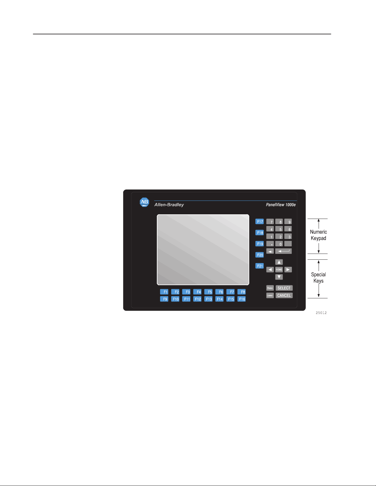
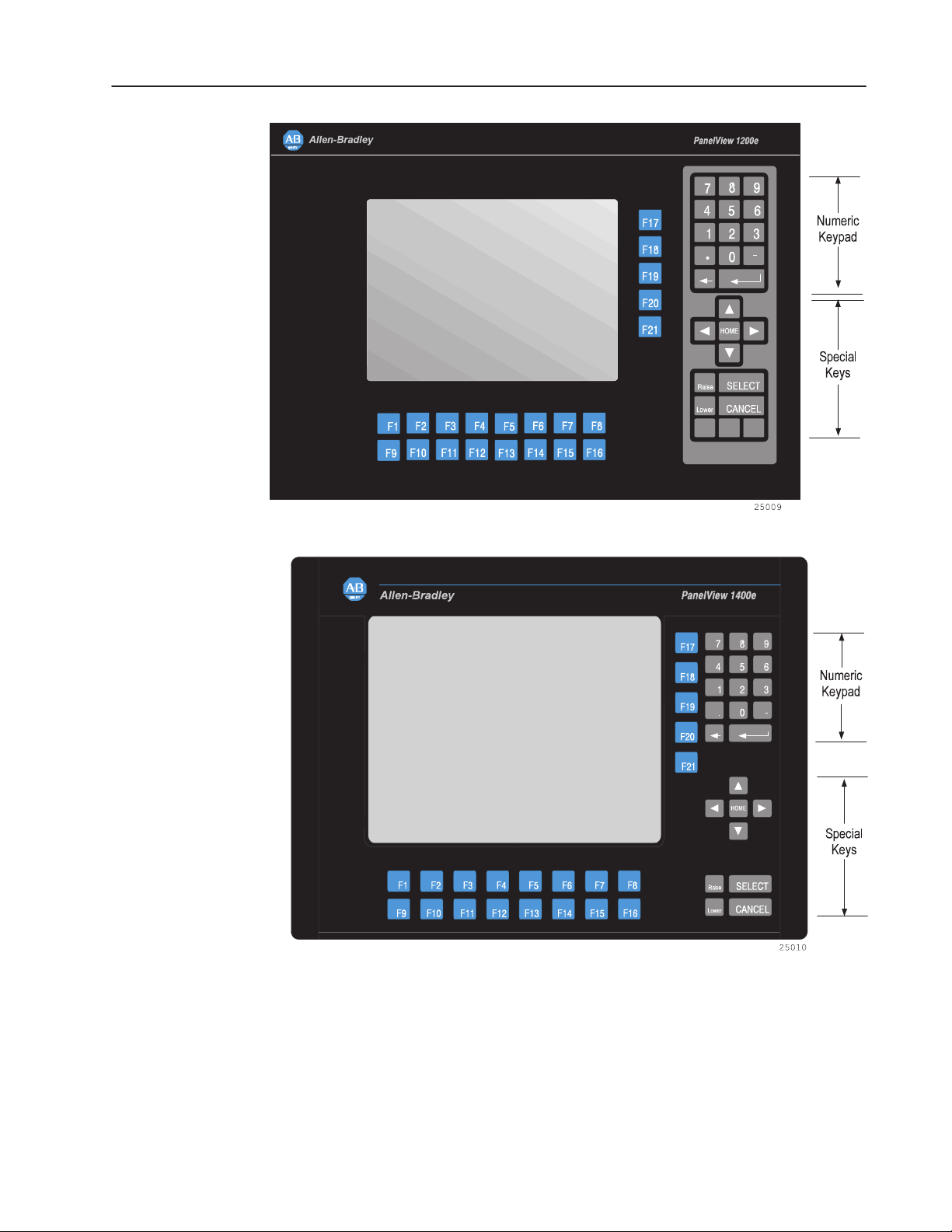
Keypad Terminals
The keypad terminal has:
• 21 user-definable function keys
• a keypad for entering numeric values
• up, down, left, and right arrow keys
• Home, Enter, Select, Cancel, Raise, Lower, and Backspace keys
The user-definable function keys on keypad terminals are pre-labeled
at the factory, but you can create key labels (legends) to suit your
application. The replacement key legends slide in from the rear of
the faceplate. The Legend Kit, included with your shipment,
provides blank card material that accepts most types of markers or
paste-on labels.
Figure 1.1 1000e, 1200e, and 1400e Keypad Terminals (Front
View)
Publication 2711E-821 – January 1998
Page 20
1–7Introducing the PanelView Terminals
Publication 2711E-821 – January 1998
Page 21

1–8 Introducing the PanelView Terminals
Function Keys
When creating screens, you can assign any of the 21 function keys to
objects so they do several tasks, such as turning on PLC input bits or
changing screens. Keys can have different task assignments for each
screen created.
Numeric Keypad
The keypad terminal has a numeric input keypad that includes
number keys, Enter, Backspace, – (negative), and . (decimal) keys.
To make a numeric entry, you call up a pop-up Numeric Entry
Scratchpad that displays the numbers as you type. You can send the
data to the PLC controller.
Special Keys
The keypad terminal includes special keys:
• the arrow keys and Home are used to navigate through Set Bit
Cursor and Numeric Input Cursor Points, or the ASCII input
object
• Select is used with the Set Bit Cursor and Numeric Input Cursor
Points to pop up the numeric entry scratchpad
• Cancel can be used with all numeric keypads, Set Bit Cursor and
Numeric Input Cursor Points to remove the numeric entry
scratchpad
• Raise and Lower are used with Numeric Input Cursor Point only,
to change the numeric value sent to the PLC
The three blank keys on the bottom right of the 1200e terminals are
reserved for future development and cannot be configured.
Refer to the PanelBuilder 1400e Configuration Software for
Windows User Manual for details.
Publication 2711E-821 – January 1998
Page 22
1–9Introducing the PanelView Terminals
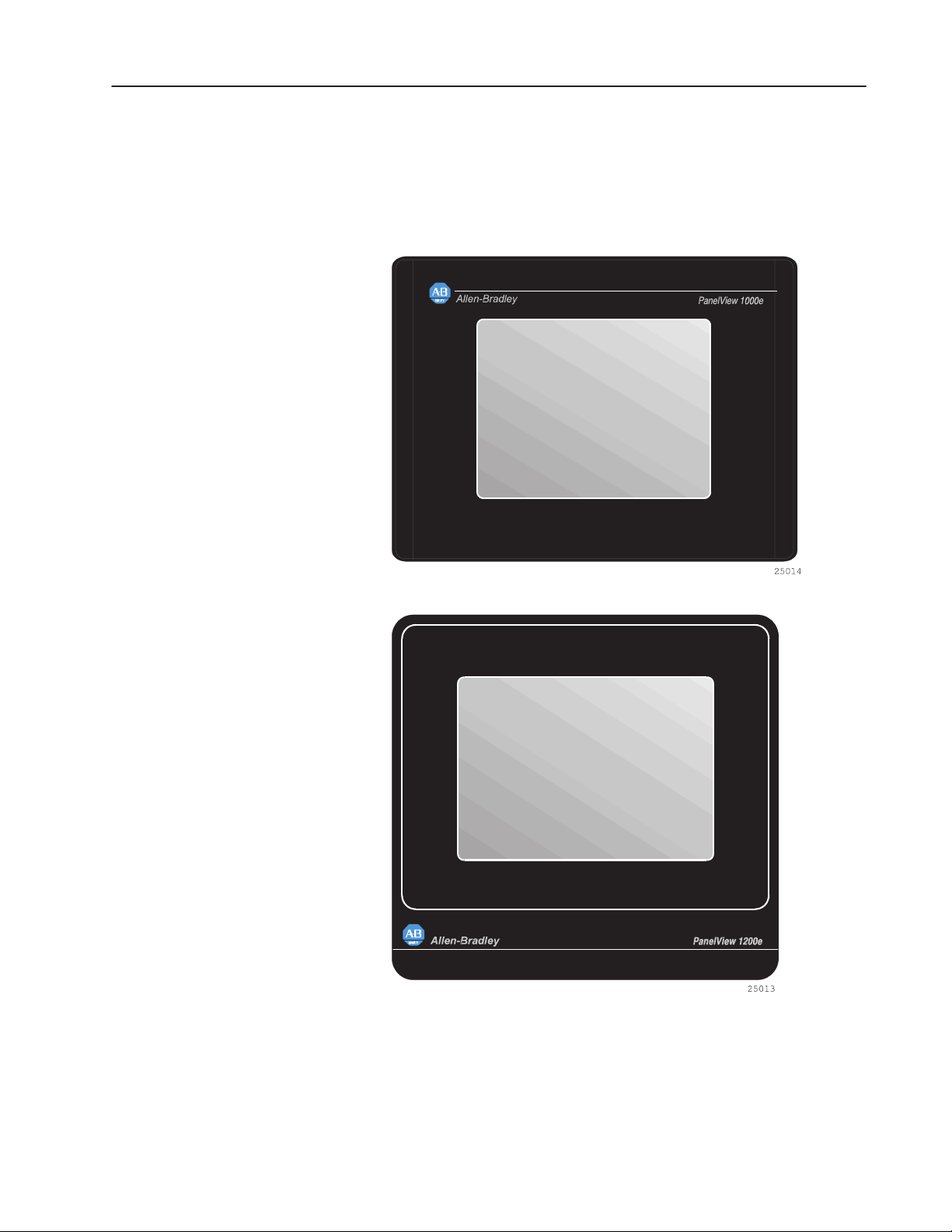
Touch Screen Terminals
To operate a touch screen terminal, you press buttons directly on the
screen.
Figure 1.2 1000e, 1200e, and 1400e Touch Screen Terminals (Front
View)
Publication 2711E-821 – January 1998
Page 23

1–10 Introducing the PanelView Terminals
The 1200e touch screen contains 120 touch cells, laid out in a 10-cell
by 12-cell grid. Each touch cell is 64 pixels wide by 40 pixels high.
For the 1000e and 1400e analog touch screen, the minimum touch
object size is 40 by 40 pixels. There is no touch matrix for the 1000e
and 1400e touch screens so the objects can be placed at any location.
In PanelBuilder, a grid can be made visible to allow you to align
screen objects.
Touch cells are grouped to create different types and sizes of buttons.
You can activate input functions by touching the appropriate object
on the terminal and can configure the terminal to beep when a touch
cell is pressed.
The PanelView 1000e and 1400e Touch Screen terminals use
analog-resistive touch screens. This allows input objects to be any
size (minimum 40 by 40 pixels) and to be placed anywhere on the
screen. The analog-resistive touch screen provides greater flexibility
in screen design compared to PanelView 1200 and 1200e terminals.
PanelView 1200 and 1200e terminals use a touch matrix which
requires that all input objects align with a touch grid.
Publication 2711E-821 – January 1998
Page 24

1–11Introducing the PanelView Terminals
ATTENTION: In the unlikely event that two or more
touches occur simultaneously in the same horizontal or
!
vertical line, an input object located half-way between
the two touches could be activated. This is inherent in
the analog-resistive touch screen technology that is
used in PanelView 1000e and 1400e terminals.
PanelBuilder 1400e Configuration Software
PanelBuilder 1400e Configuration Software for Windows is an
easy-to-learn tool for developing complex applications quickly and
efficiently. You run PanelBuilder 1400e Configuration Software on a
personal computer to develop operator interface applications for
PanelView 1000e, 1200e, or 1400e operator terminals.
The Windows platform offers many advantages. In addition to a
superior graphical interface, you can work within several
applications at once and transfer information between them easily.
Features of the PanelView Terminals
Figures 1.1 and 1.2 show the front view of the PanelView 1000e,
1200e, and 1400e terminals. The back of each terminal is shown in
the installation chapter for each terminal type.
The PanelView 1000e, 1200e, and 1400e terminals differ from the
PanelView 1200 terminal as follows:
• Remote I/O, DH+, and ControlNet connectivity are now available
(used one at a time).
• The PanelView 1000e terminal is available in four models:
– color touch screen clip mount (2711E-T10C6)
– color keypad clip mount (2711E-K10C6)
– color touch screen clip mount with ControlNet support
(2711E-T10C7, 2711E-T10C15)
– color keypad clip mount with ControlNet support
(2711E-K10C7, 2711E-K10C15)
• The PanelView 1200e terminal is available in four models:
– color touch screen clip mount (2711E-T12C6)
– color touch screen stud mount (2711E-T12C4)
– color keypad stud mount (2711E-K12C6)
– color keypad stainless steel stud mount (2711E-K12C6L2)
Publication 2711E-821 – January 1998
Page 25

1–12 Introducing the PanelView Terminals
• The 1400e terminal is available in four models:
– color touch screen stud mount (2711E-T14C6)
– color keypad stud mount (2711E-K14C6)
– color touch screen stud mount with ControlNet support
– color keypad stud mount with ControlNet support
• The front panels of the PanelView 1000e, 1200e, and 1400e
terminals have new graphics.
• The PanelView 1000e and 1400e terminals have analog touch
screens.
• The PanelView 1400e terminal has an analog touch screen with
built-in, anti-glare glass.
• The PanelView 1000e terminals run firmware versions 3 and
above only. The PanelView 1200e and 1400e terminals run
firmware versions 1 and above. The application you run on
PanelView 1000e, 1200e, and 1400e terminals is displayed in a
pixel graphics format, rather than a character-based format.
• The logic board has a communication slot for communication
options, such as ControlNet.
(2711E-T14C7, 2711E-T14C15)
(2711E-K14C7, 2711E-K14C15)
ATTENTION: The Keyboard port is not currently
supported by the PanelView Firmware. Connecting a
!
Table 1.D outlines the main changes that have been made to the
memory configuration on the terminal’s logic board.
keyboard could produce unpredictable results, and
could reset the terminal.
Publication 2711E-821 – January 1998
Page 26

Table 1.D Memory Configuration on PanelView 1200 (Series
F and above) and PanelView 1000e, 1200e, and 1400e
Operator Terminals
1–13Introducing the PanelView Terminals
Memory Type PanelView 1000e
Terminal
User RAM (SRAM)
(Battery-backed)
Flash 1.75 MB for
E/EPROM N/A Optional 64K/128K
PCMCIA memory
card support
128K of
battery-backed
static RAM (stores
the terminal
configuration
parameters, alarm
status and history,
retentive data; no
application file
storage)
firmware; 2.25 MB
for application file
storage
Provides
application file
storage up to
15.75 MB
PanelView 1200
Terminal (Series F
and Above)
128K (stores the
terminal
configuration
parameters, alarm
history, and
application file)
256K (stores
firmware and
BIOS); no flash for
application file
storage
E/EPROM (provide
backup application
file storage)
1.75 MB for
firmware;
application file
storage up to
2.25 MB for
enhanced F and
above terminals
PanelView 1200e
and 1400e
Terminals
128K of
battery-backed
static RAM (stores
the terminal
configuration
parameters, alarm
status and history,
retentive data; no
application file
storage)
1.75 MB for
firmware; 256K for
application file
storage
N/A
Provides
application file
storage up to
15.75 MB
New Features of the PanelView Terminals
Version 3 Firmware Features
PanelView Version 3 firmware supports the following PanelBuilder
features:
• Goto Configure Mode button
• PanelView 1000e applications
• Retain Cursor On Cancel feature
• Modbus Communications (with the Modbus Communications
Kit, A-B Catalog Number 2711E-UMOD)
Version 4 Firmware Features
PanelView Version 4 firmware supports a maximum of 1500 alarm
history records.
Publication 2711E-821 – January 1998
Page 27

1–14 Introducing the PanelView Terminals
Applicable Programmable Controllers and Connections
PanelView terminals can be connected to any Allen-Bradley 1771
Remote I/O, Data Highway Plus, or ControlNet link. Applicable host
controllers include almost all Allen-Bradley Programmable Logic
Controllers, as well as certain IBM computers, interface cards, VME
Controllers, and the DEC Q-Bus interface.
Newly-released Allen-Bradley programmable controllers not yet
listed will support PanelView terminals as long as they support 1771
Remote I/O, DH+, or ControlNet networks.
Remote I/O Communications
The terminal can occupy up to 64 I/O racks in a PLC. It has
the same configurability—and more—as a standard I/O rack. Refer
to your applicable Allen-Bradley Programmable Controller and
Remote I/O Scanner user’s manuals for connection and Remote I/O
configuration limitations.
The following host controllers can be connected to the terminals over
a Remote I/O link.
PLC-5/11, 5/15, 5/20, 5/25, 5/30, 5/40, 5/60, 5/80 and 5/250
Processors
You can connect one or more terminals directly to a PLC-5 Remote
I/O Port (in Scanner Mode) with other I/O racks. If the PLC-5
Remote I/O Port is used in the adapter mode, one or more terminals
can be connected to that PLC-5 along with other I/O racks via a
1771-SN I/O Subscanner Module.
The terminals can communicate at 57.6, 115.2, and 230.4 kilobauds
with any PLC-5 that can support those baud rates.
If you are using a PLC-5/15 with partial rack addressing and block
transfers, you must use PLC-5/15 Series B, revision J or later.
PLC-5/10 Processor
One or more terminals can be connected to this processor with other
I/O racks by a 1771-SN I/O Subscanner Module.
PLC-3 and PLC-3/10 Processors
One or more terminals can be connected directly to a PLC-3 or
PLC-3/10 remote I/O Scanner along with other I/O racks.
If you are using a 1775-S4A Remote Scanner/Distribution panel, you
must use Series B or higher.
Publication 2711E-821 – January 1998
Page 28

1–15Introducing the PanelView Terminals
PLC-2 Family Processors via 1771-SN or 1772-SD2
The PLC-2 family includes the PLC-2/05, 2/15, 2/20, and 2/30. One
or more terminals can be connected to these processors with other
I/O racks by the 1771-SN I/O Subscanner Module.
If you are using a 1772-SD2 Scanner/Distribution panel, you must
use Revision 3 or later.
SLC-5/02, 5/03, or 5/04 via 1747-SN Series A or B
One or more terminals can be connected to the 1747-SN I/O
Subscanner Modules (SLC-RIO connection) for the SLC processors.
Each module provides an additional remote I/O link for the host
programmable controller. The rack range of the 1747-SN Series A or
B is 0 to 3.
Important: The 1747-SN Series A supports only discrete data
whereas Series B also provides block transfer support.
Series B also supports Pass-Through communication
capability when used with the 5/04.
1771-SN I/O Subscanner Module
One or more 1771-SN I/O Subscanner Modules can be installed in
any standard Allen-Bradley 1771 I/O rack. Each module provides an
additional Remote I/O link for the host programmable controller.
One or more terminals can be connected to any of the previously
mentioned processors along with other I/O racks via a 1771-SN I/O
Subscanner Module. Refer to the 1771-SN Sub I/O Scanner Module
Data Sheet for specific details.
6008-SI IBM PC I/O Scanner
This module can be installed in an IBM PC or compatible
computer to provide the computer with an Allen-Bradley 1771
Remote I/O Link. You can then connect Allen-Bradley Remote I/O
racks and devices such as the PanelView 1000e/1200e/1400e
terminal to this computer.
6008-SV VME I/O Scanner
This module can be installed in a VME backplane, providing the
VME controller with an Allen-Bradley 1771 Remote I/O Link.
Allen-Bradley Remote I/O racks and devices such as the PanelView
1000e/1200e/1400e terminal can then be connected to this VME
controller.
Publication 2711E-821 – January 1998
Page 29

1–16 Introducing the PanelView Terminals
6008-SQ DEC Q-BUS I/O Scanner
This module can be installed into a DEC Q-Bus controller to provide
it with an Allen-Bradley 1771 Remote I/O Link. Allen-Bradley
Remote I/O racks and devices such as the PanelView
1000e/1200e/1400e terminal can then be connected to this controller.
DH+ Communications
The terminal can be directly connected to a DH+ network so it can
communicate with several controllers simultaneously. It can be
connected to the SLC-5/04 and the following PLC-5 host controllers
over DH+.
PLC-5/10, 5/11, 5/15, 5/20, 5/25, 5/30, 5/40, 5/60, 5/80, 5/40L,
5/60L, 5/80L
One or more terminals can be connected directly to one of the PLC-5
family of programmable controllers over DH+ so it can
communicate with several controllers simultaneously.
SLC-5/04
One or more terminals can be connected directly to one of the
SLC-5/04 family of programmable controllers over DH+ so it can
communicate with several controllers simultaneously.
PLC2/PLC3
The terminal supports communications to one or more PLC2s or
PLC3s via offlink addressing: the PLC2 also communicates by a
1785-KA module (DH+ to DH bridge), while PLC3 communication
is by a 1775-KA module.
ControlNet Communications
To communicate on ControlNet, install the ControlNet
Communication Interface Card (A-B Catalog Number 1784-KTCX,
Series B or later) in your PanelView terminal. This card enables the
terminal to communicate with devices on the ControlNet network
and also acts as an interface between the terminal and ControlNet for
ControlNet-Direct application file transfers. The 1784-KTCX card is
pre-installed in PanelView 1000e and 1400e operator terminals (A-B
Catalog Numbers 2711E-K10C7, 2711E-T10C7, 2711E-K14C7, and
2711E-T14C7).
Publication 2711E-821 – January 1998
Page 30
1–17Introducing the PanelView Terminals
The ControlNet network is scheduled to be upgraded to Version 1.5.
To use Version 1.5 of ControlNet, you will have to upgrade all
ControlNet devices, including the firmware on the KTCX card.
Follow all upgrade procedures included in the ControlNet upgrade.
For Version 1.5 availability, contact your Allen-Bradley Sales
Representative.
For information about installing communication cards in the
PanelView terminal see PanelView ISA Card Adapter Installation
Data Sheet, A-B publication 2711E-5.6.
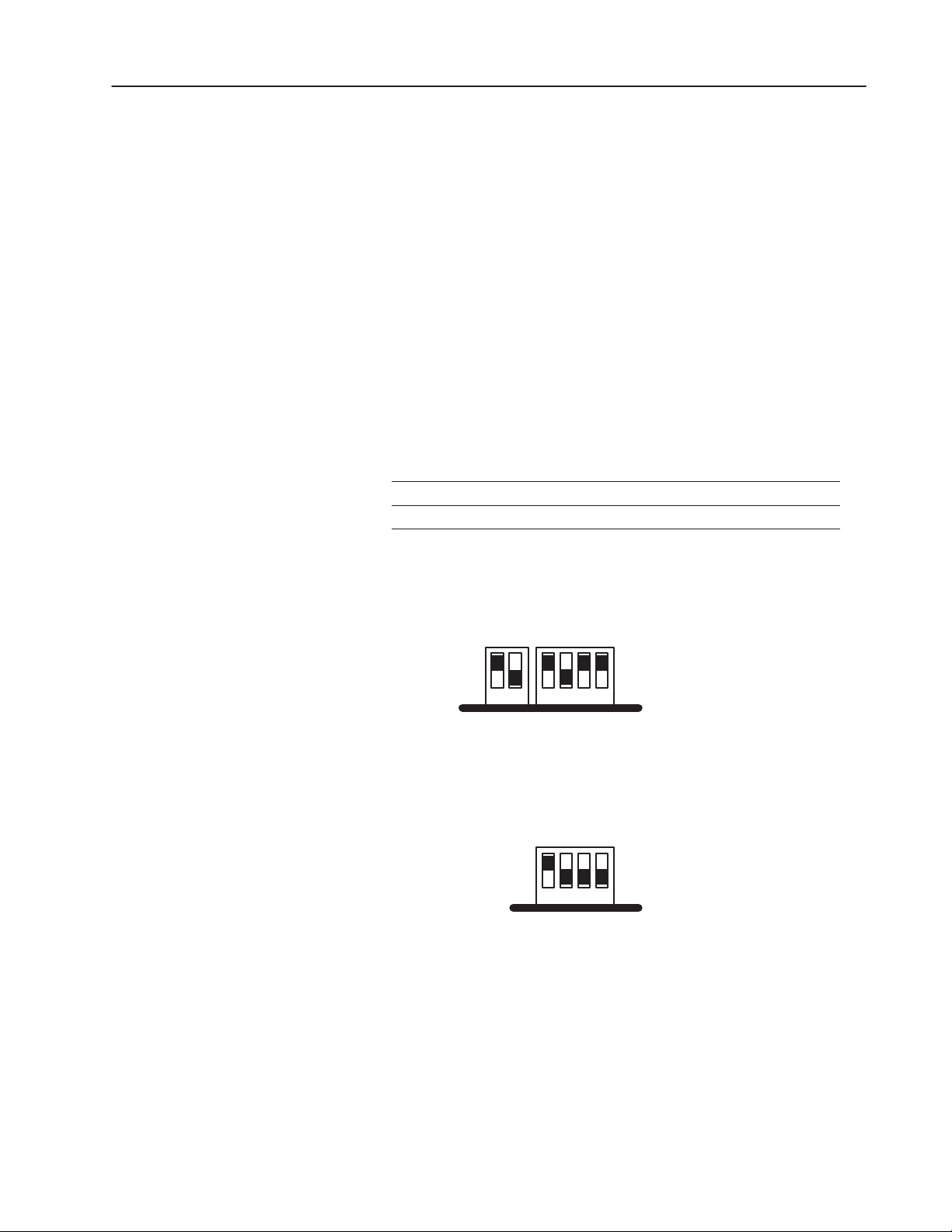
Important: The DIP switch settings on the KTCX card must be
configured to work with PanelView. If the settings have
been changed and you want to use the card in the
PanelView terminal, you must use the DIP switches on
the KTCX card to select the following addresses:
Address Setting
Base Memory
Base I/O 220
D400:0000
Figure 1.3 KTCX Switch Settings – Base Memory Address
Base Memory Address D400:0000
up (1)
12 1234
down (0)
Figure 1.4 KTCX Switch Settings – Base I/O Address
Base I/O Address 220
up (1)
1234
down (0)
For more information, see the documentation that comes with the
KTCX card.
For more information about communication devices for ControlNet,
see the PanelBuilder 1400e Configuration Software for Windows
User Manual, A-B publication 2711E-819.
Publication 2711E-821 – January 1998
Page 31

1–18 Introducing the PanelView Terminals
You may notice a delay of 5 to 10 seconds when you switch from
Configure to Run mode to execute ControlNet applications. During
this time, the message “Initializing Communications” appears on the
screen. The delay occurs because the KTCX card has a separate
processor that takes 5 to 10 seconds to synchronize with ControlNet.
When you switch to Run mode the application screen will appear
after approximately 5 seconds. Then the message “Communication
Lost” will appear for approximately 5 seconds, while the connection
is established.
PLC-5/20C, 5/40C, 5/60C, 5/80C
The PanelView terminal can be connected to the PLC-5C enhanced
family of programmable controllers over ControlNet.
Publication 2711E-821 – January 1998
Page 32

Installing PanelView 1000e
Terminals
Overview
This chapter explains how to install a PanelView 1000e terminal in
your plant. Specifically, it provides:
• terminal dimensions
• a list of tools for installing the terminal
• cutout dimensions for panel mounting
• information about mounting options
This chapter also provides information about the correct use of the
following hardware features, specifically:
• how to switch modes
• how to connect power to the terminal
• how to connect a serial printer
• how to connect an external alarm relay
• how to connect a terminal to your PLC system
• information about the Upload/Download cables and PCMCIA
cards
Figure 2.1 shows the rear and bottom panel of the PanelView 1000e
terminal. Note the location of the power connector, alarm relay
connector, RS-232 port, and Remote I/O and DH+ connector.
Power Connector
Figure 2.1 Rear and Bottom View of PanelView 1000e
Terminal
Run/Configuration Switch
Alarm Relay Connector
RS-232 Port
Remote I/O DH+ Connector
2
ISA Card Slots
1
PCMCIA Memory
2
Card Slots (Slot 1
1
is active; slot 2 is
inactive and has a
protective label
cover.)
24771
Publication 2711E-821 – January 1998
Page 33

2–2 Installing PanelView 1000e Terminals
PanelView 1000e Terminal Dimensions
Clip Slot
0.15”
(3.81 mm)
0.69”
(18 mm)
10.03”
(255 mm)
1.2”
(30.4 mm)
0.53”
(13 mm)
8.43”
(224 mm)
Figure 2.2 shows the dimensions of the keypad terminals.
Figure 2.2 PanelView 1000e Keypad Terminal Dimensions
11.12”
(282 mm)
3.64”
(92 mm)
F2
F1
F3 F4 F5 F6 F7
F10
F9 F11 F12 F13 F14 F15 F16
F9 F11 F12 F13 F14 F15 F16F10
5.43”
(138 mm)
F17
F18
F19
F20
F21
F8
1.06”
(27 mm)
6.15”
(156 mm)
0.94”
(24 mm)
0.69”
(18 mm)
4.48”
(114 mm)
4.48”
(114 mm)
1.37”
(35 mm)
Allen–Bradley
3.2”
(81 mm)
1.46”
(37 mm)
PanelView 1000e
7
89
456
123
.
0
Home
Raise SELECT
Lower
CANCEL
(113 mm)
–
0.69”
(18 mm)
4.45”
6.8”
(173 mm)
0.95”
(24 mm)
11.11”
(282 mm)
0.9”
(23 mm)
0.55”
(14 mm)
6.15”
(156 mm)
(17 mm)
0.65”
16.64”
(423 mm)
24751
Publication 2711E-821 – January 1998
Page 34

0.7”
(18 mm)
10.03”
(255 mm)
1.2”
(30 mm)
8.43”
(224 mm)
Clip Slot
0.15”
(3.81 mm)
Figure 2.3 shows the dimensions of the touch screen terminals.
Figure 2.3 PanelView 1000e Touch Screen Terminal
Dimensions
0.69”
(18 mm)
4.45”
(113 mm)
(24 mm)
11.11”
(282 mm)
1.06”
(27 mm)
(13 mm)
0.5”
0.94”
(24 mm)
0.69”
(18 mm)
4.48”
(114 mm)
1.37”
(35 mm)
Allen–Bradley
3.64”
(92 mm)
11.12”
(282 mm)
(106 mm)
4.17”
0.85”
(22 mm)
PanelView 1000e
2–3Installing PanelView 1000e Terminals
1.2”
(30 mm)
6.83”
(174 mm)
0.96”
0.55”
(14 mm)
0.9”
(23 mm)
6.18”
(157 mm)
0.65”
(17 mm)
4.48”
(114 mm)
14.58”
(370 mm)
3.75”
(95mm)
Allow 3.75” at this side
internally so that unit can
be opened for replacing
backlight module.
24752
Publication 2711E-821 – January 1998
Page 35

2–4 Installing PanelView 1000e Terminals
Tools for Installing Your PanelView 1000e Terminal
"
You need the following tools to make a wall or panel cutout and
install a PanelView 1000e terminal in it. The terminal shipment
includes a terminal cutout template for your use.
Note: Converted metric values have been rounded off. This applies
to the dimensions specified in the drawings in this chapter.
To make a rectangular wall or panel cutout, you need these tools:
• center punch
• scriber
• hammer
• power jig saw
• set of drill bits (1/8 to 3/8 inch)
• metal ruler for drawing lines on the panel
• power drill
• torque wrench
• metal file
To install the terminal, you need this tool:
• slot screwdriver or Phillips screwdriver
Mounting Options for PanelView 1000e Terminals
"
You can install your PanelView 1000e terminal in a rectangular
cutout in a panel or wall or in a 19-inch rack with the adapter kit.
The terminals are mounted with mounting clips.
Note: When choosing a location in which to install the PanelView
terminal, we recommend you provide at least 3.75 inches (9.5 cm)
clearance around the terminal from the panel or rack in which it is
installed, for proper ventilation.
Mounting a Clip-Mount Touch Screen Terminal in a Panel or Wall
Cutout
T o prepare the location:
1. Make the appropriate cutout in the wall or panel location. Figure 2.4
shows the cutout dimensions for the clip-mount terminal.
2. Insert the terminal into the panel or wall cutout.
Publication 2711E-821 – January 1998
Page 36

Figure 2.4 Clip-Mount Touch Screen Terminal Panel
Cutout
2–5Installing PanelView 1000e Terminals
Bezel Border Line
C
L
C
L
10.11”
(257 mm)
11.11”
(282 mm)
CUTOUT
13.29”
(338 mm)
14.58”
(370 mm)
Eight assembled mounting clips are provided with the clip-mount
touch screen terminals; only six clips are used for the mount.
T o install the clips:
1. Make sure the gasket is installed. If not, NEMA 4X will not be
met.
2. Install the six mounting clips (2 on top, 2 on bottom, 1 on each
side). The ends of the clips slide into the slots on the terminal.
24756
3. Tighten the mounting clip screws by hand until the gasket seal
contacts the mounting surface uniformly. See Figures 2.5 and 2.6
for details.
Publication 2711E-821 – January 1998
Page 37

2–6 Installing PanelView 1000e Terminals
Figure 2.5 Touch Screen Clip Mount (Side View)
Screw Driver Slot
Mounting
Mounting Slot
Upper Right Side
Touch Screen
Terminal Front Bezel
Figure 2.6 Touch Screen Clip Mount (Back View)
Clip
Gasket
Rack Mount Adapter
or User Panel
Front Bezel
24772
Mounting Slot
Foot Pad
Panel Mount Screw
Mounting Clip
Screw Driver Slot
24780
4. Tighten the mounting clip screws to a torque of 10 inch-pounds. Do
not over-tighten.
ATTENTION: Tighten mounting clips to a torque of
10 inch-pounds to provide a proper seal and to prevent
!
potential damage to the terminal. Allen-Bradley
assumes no responsibility for water or chemical
damage to the terminal or other equipment within the
enclosure because of improper installation.
Publication 2711E-821 – January 1998
Page 38

2–7Installing PanelView 1000e Terminals
5. Remove the protective installation label covering the top vents of
the terminal.
ATTENTION: Remove the protective installation
label covering the top vents to prevent overheating and
!
damage to the terminal.
Mounting a Clip-Mount Keypad Terminal in a Panel or Wall
Cutout
T o prepare the location:
1. Make the appropriate cutout in the wall or panel location. Figure 2.7
shows the cutout dimensions for the clip-mount terminal.
2. Insert the terminal into the panel or wall cutout.
Figure 2.7 Clip-Mount Keypad Terminal Panel Cutout
Bezel Border Line
C
L
C
L
10.11”
(257 mm)
11.11”
(282 mm)
CUTOUT
15.35”
(390 mm)
16.64”
(423 mm)
Eight assembled mounting clips are provided with the clip-mount
keypad terminals; only six clips are used for the mount.
3. Make sure the gasket is installed. If not, NEMA 4X will not be
met.
T o install the clips:
1. Install the six mounting clips (2 on top, 2 on bottom, 1 on each
side). The ends of the clips slide into the slots on the terminal.
24755
2. Tighten the mounting clip screws by hand until the gasket seal
contacts the mounting surface uniformly. See Figures 2.8 and 2.9
for details.
Publication 2711E-821 – January 1998
Page 39

2–8 Installing PanelView 1000e Terminals
Figure 2.8 Keypad Terminal Clip Mount (Side View)
Screw Driver Slot
Mounting Slot
Upper Right Side
Touch Screen
Terminal Front Bezel
Gasket
Rack Mount Adapter
or User Panel
Mounting
Clip
Figure 2.9 Keypad Terminal Clip Mount (Back View)
Mounting Slot
Foot Pad
Panel Mount Screw
Mounting Clip
Screw Driver Slot
Front Bezel
24780
24772
3. Tighten the mounting clip screws to a torque of 10 inch-pounds.
Do not over-tighten.
Publication 2711E-821 – January 1998
ATTENTION: Tighten mounting clips to a torque of
10 inch-pounds to provide a proper seal and to prevent
!
potential damage to the terminal. Allen-Bradley
assumes no responsibility for water or chemical
damage to the terminal or other equipment within the
enclosure because of improper installation.
Page 40

2–9Installing PanelView 1000e Terminals
4. Remove the protective installation label covering the top vents of
the terminal.
ATTENTION: Remove the protective installation
label covering the top vents to prevent overheating and
!
damage to the terminal.
Mounting a Touch Screen Terminal in a 19-inch Rack
To mount the PanelView 1000e Clip-Mount Touch Screen terminals
in a standard 19-inch EIA rack, you need a Rack Mount Kit (A-B
Catalog Number 2711-NR6T). This kit consists of a rack adapter and
mounting hardware.
Mounting a Keypad Terminal in a 19-inch Rack
To mount the PanelView 1000e Clip-Mount Keypad terminals in a
standard 19-inch EIA rack, you need a Rack Mount Kit (A-B
Catalog Number 2711-NR6K). This kit consists of a rack adapter and
mounting hardware.
Setting Up the PanelView 1000e Terminal
"
You have several options for setting up the terminal. Figure 2.1
shows the locations of the options described in the remainder of this
chapter.
Switching Modes
The terminal operates in Configure and Run modes. Configure mode
lets you set up the terminal and Run mode executes the application
file. To switch between modes, you can use either of the following
methods:
• the hardware Mode Select Keyswitch, located at the back of the
terminal
• the Software Mode Switch (available in PanelView firmware
version 3 and above) that you can set to Enable or Disable from
the Terminal Configuration screen. For details, see Mode Switch
in Chapter 5 of this manual.
Note: The terminal communicates with your PLC only when the
terminal is in Run mode, so set it to this mode to monitor and control
your PLC application.
Publication 2711E-821 – January 1998
Page 41

2–10 Installing PanelView 1000e Terminals
Backlight Intensity
You can adjust the terminal display intensity while in Configure
mode. For details on how to increase or decrease terminal display
intensity, see Chapter 5, Configuring PanelView Operator Terminals,
in this manual. The terminal display is initially set at the maximum
intensity.
Connecting Power to the Terminal
The power requirements for the terminal are 115 Vac (60 Hz) or
230 Vac (50 Hz).
Before connecting the power cable to the power connector at the
bottom of the terminal, make sure the cable is not carrying power.
Because the terminal has no power switch, connecting the ac power
will start the terminal if power is present in the cable.
!
ATTENTION: Be sure to connect the wire to Ground
(GND) on the power connector. Failure to do so could
result in electrical hazard to the operator (and damage
to the equipment).
T o connect power to the terminal:
1. Prepare the power wires by stripping the wire of its protective
coating to a length of to of an inch (1 to 2 cm).
2. Turn the screw on the power connector counterclockwise to open
the wire slot. Insert the wire fully into its appropriate slot.
3. Turn the screw clockwise until the wire is held firmly in place.
4. Repeat the procedure until all three power wires are connected.
Figure 2.10 The Power Connector
L1
L2
GND
L1 ~ (Vac)
L2N ~ (Vac)
(Protective Earth)
20164
Publication 2711E-821 – January 1998
Page 42

2–11Installing PanelView 1000e Terminals
Connecting the Upload/Download Cable
The RS-232 port connects the terminal to the host computer for
uploading and downloading application files using the RS-232 serial
cable (Upload/Download cable). Cables of different lengths are
available in separate kits (A-B Catalog Numbers 2711-NC13,
2711-NC14, 2706-NC13).
The Upload/Download cable can be connected to a computer with a
9-pin, RS-232 port (IBM PC ATR-type computers). Use the cable
pinout shown in Figure 2.11 to connect the terminal to the host
computer. For instructions about transferring files using the
Upload/Download cable, refer to the PanelBuilder 1400e
Configuration Software for Windows User Manual or the PanelView
1200/1400e Transfer Utility User Manual.
Figure 2.11 RS-232 Port Pinout for Upload/Download Cable
Connection
PanelView Terminal Cable End
RS-232 Port Pinout
Female, 9-pin
DCD (1)
TXD (2)
RXD (3)
DSR (4)
Common (5)
DTR (6)
CTS (7)
RTS (8)
N/C (9)
Host Computer Cable End
RS-232 Port Pinout
Female, 9-pin
DCD (1)
RXD (2)
TXD (3)
DTR (4)
Common (5)
DSR (6)
RTS (7)
CTS (8)
N/C (9)
Connecting the Serial Printer
You will need to construct your own cable to connect a serial printer
to the terminal. Use the pinout shown in Figure 2.12 to construct the
PanelView terminal end of this cable. To construct the printer end of
the cable, consult the user manual for your printer.
Figure 2.12 RS-232 Port Pinout for Serial Printer Cable
Construction
RXD
DSR
(ground)
Pin 5
Pin 9
N/C
RTS
RS-232 Serial Interface
Female, D-sub, 9-pin connector
TXD
DCDCommon
Pin 1
Pin 6
DTR
CTS
20387
Publication 2711E-821 – January 1998
Page 43

2–12 Installing PanelView 1000e Terminals
Connecting an External Alarm Relay
The terminal can be used to trigger a remote alarm or warning light
under specific conditions. See Appendix A, Specifications, in this
manual for the voltage range of the alarm relay.
!
!
T o attach a remote alarm or light to the alarm relay connector:
ATTENTION: Do not use this relay for control
functions of any kind.
ATTENTION: The 1000e external alarm relay is rated
for 24 V ac or dc, and 1.0A. Do not exceed the rated
values. The external alarm relay is different for the 1200e
and 1400e terminals.
1. Prepare the wires by stripping them of their insulation to a length
of to of an inch (1 to 2 cm).
2. Turn the screw on the alarm relay plug counterclockwise to open
the wire slot.
3. Insert the wire fully into its appropriate slot. Figure 2.13 shows the
slots.
4. Turn the screw clockwise until the wire is held firmly in place.
5. Repeat the procedure until all three wires are connected.
Figure 2.13 The Remote Alarm Connector
On bottom of PanelView 1000e
Terminal
(Refer to Figure 2.1)
Alarm Relay Plug
Normally
Closed
Common
Normally
Open
No
Connect
Publication 2711E-821 – January 1998
20388
Page 44

2–13Installing PanelView 1000e Terminals
Connecting a Terminal to Your PLC System
Figure 2.14 shows the Remote I/O and DH+ connector on the bottom
of the terminal. This connects the terminal to the host PLC over
Remote I/O or DH+.
Figure 2.14 Remote I/O and DH+ Connector
On bottom of PanelView 1000e Terminal
(Refer to Figure 2.1)
Remote I/O and DH+ Plug
provided with installation kit
Remote I/O
PanelView Terminal PLC
2
SHIELD
Pin1 Blue
Shield
Pin 2 Clear
1
DH+
PanelView Terminal PLC
Pin1 Blue
Shield
Pin 2 Clear
Pin 1 Blue
Shield
Pin 2 Clear
Pin 2 Blue
Shield
Pin 1 Clear
20163
"
T o connect the PanelView 1000e terminal over Remote I/O:
1. Remove the Remote I/O and DH+ connector plug from the
bottom of the terminal. Figure 2.1 shows its location.
2. Back out plug terminal screws 2 and 1 on the connector. See
Figure 2.10 for plug connection locations.
3. Connect the clear wire to plug terminal 2 and the blue wire to
plug terminal 1. Connect shield and shield drain wire to middle
plug terminal. Tighten the screws to secure the wires.
4. Re-insert the plug into the terminal connector.
Note: If the terminal is the last device on the link, connect a 1/2 watt
terminating resistor across terminals 1 and 2. The value of the
resistor depends on the Remote I/O baud rate:
• for 57.6 kilobaud and 115.2 kilobaud, use a 150-ohm resistor
(A-B Part Number 740018-29)
• for 230 kilobaud, use an 82-ohm resistor (A-B Part Number
740018-23)
Publication 2711E-821 – January 1998
Page 45

2–14 Installing PanelView 1000e Terminals
T o connect the PanelView 1000e terminal to the DH+ network:
1. Remove the Remote I/O and DH+ connector plug from the rear of
the terminal.
2. Back out plug terminal screws 2 and 1 on the connector. See
Figure 2.14 for plug connection locations.
3. Connect the blue wire to plug terminal 1 and the clear wire to
plug terminal 2. Connect shield and shield drain wire to middle
plug terminal. Tighten the screws to secure the wires.
4. Re-insert the plug into the terminal connector.
"
Note: If the terminal is the last device on the link, connect a 1/2 watt
terminating resistor across terminals 1 and 2. The value of the
resistor depends on the DH+ baud rate:
• for 57.6 kilobaud and 115.2 kilobaud, use a 150-ohm resistor
(A-B Part Number 740018-29)
• for 230 kilobaud, use an 82-ohm resistor (A-B Part Number
740018-23)
T o connect the PanelView 1000e terminal to the ControlNet network:
The PanelView 1000e terminal (A-B Catalog Number 2711E-T10C6
and 2711E-K10C6) requires an enhancement with a 1784-KTCX or
1784-KTCX15 card and 2711E-NA2 adapter. You can use the
ControlNet-enhanced PanelView 1000e terminals (A-B Catalog
Number 2711E-T10C7, 2711E-T10C15, 2711E-K10C7, and
2711E-K10C15).
" Connect a PanelView Terminal to a ControlNet network via a tap
with a 1-meter (39.4-inch) drop cable. Use any tap with one of
the following catalog numbers: 1786-TPS, 1786-TPYS,
1786-TPR, or 1786-TPYR. See the ControlNet PLC-5
Programmable Controllers User Manual (A-B publication
1785-6.5.14) for more information about ControlNet taps.
Publication 2711E-821 – January 1998
"
"
Note: ControlNet taps contain passive electronics and must be
purchased from Allen-Bradley for the network to operate correctly.
Note: If the terminal is the last device on the link, connect a
75-ohm, 1-watt terminating resistor to the unused connector on the
tap (A-B Catalog Number 1786-XT).
See the ControlNet PLC-5 Programmable Controllers User Manual
(A-B publication 1785-6.5.14), the ControlNet Communication
Interface Card (A-B publication 1784-5.20), and the ControlNet
Planning and Installation Manual (A-B publication 1786-6.2.1) for
more information about ControlNet.
Page 46

2–15Installing PanelView 1000e Terminals
Using the PCMCIA Card Slots
The PCMCIA card slots support the PCMCIA memory cards, written
to in FAT file format. Only slot 1 is active. Slot 2 is covered with a
protective label. If a card is inserted to slot 2, there will be no
activity. See Figure 2.1 for the location of the PCMCIA card slots on
the bottom of your terminal.
Publication 2711E-821 – January 1998
Page 47

Installing PanelView 1200e
Terminals
Overview
This chapter explains how to install a PanelView 1200e terminal in
your plant. Specifically, it provides:
• terminal dimensions
• a list of tools for installing the terminal
• cutout dimensions for panel mounting
• information about mounting options
This chapter also provides information about the correct use of the
following hardware features, specifically:
• how to adjust contrast and brightness
• how to switch modes
• how to connect power to the terminal
• how to connect a serial printer
• how to connect an external alarm relay
• how to connect a terminal to your PLC system
• information about PCMCIA cards
Refer to Chapter 1 for information about the Upload/Download cable
and remote keyswitch assembly.
Figure 3.1 shows the rear panel of the PanelView 1200e terminal.
Note the location of the power connector, alarm relay connector,
RS-232 port, and Remote I/O and DH+ connector.
Publication 2711E-821 – January 1998
Page 48

3–2 Installing PanelView 1200e Terminals
Figure 3.1 Rear View of PanelView 1200e Terminal
Contrast Control
Fuses
Power Connector
Alarm Relay Connector
Communication Slot
PCMCIA Memory Card Slot
RS-232 Port
Mode Select Keyswitch
Remote I/O & DH+
Brightness Control
Connector
23744
Publication 2711E-821 – January 1998
Page 49

3–3Installing PanelView 1200e Terminals
PanelView 1200e Terminal Dimensions
Stud Size: #10-32
Stud Diameter: 7/32” (5.56mm)
Stud Height (from gasket to stud end):
0.5”
(12.7 mm)
1.02”
(26 mm)
Figures 3.2 and 3.3 show the dimensions of the keypad and touch
screen terminals.
Figure 3.2 PanelView 1200e Keypad Terminal Dimensions
12.46”
(316 mm)
1.71”
(43 mm)
4.35”
(110 mm)
4.35”
(110 mm)
4.8”
(122 mm)
4.35”
(110 mm)
(377 mm)
0.78”
(20 mm)
14.83”
0.36”
(9 mm)
24779
2.05”
(52 mm)
1.83”
(46 mm)
0.78”
(20 mm)
(17 mm)
4.35”
(110 mm)
0.68”
0.70”
(18 mm)
4.0”
(102 mm)
3.0”
(76 mm)
4.0”
(102 mm)
0.70”
(18 mm)
0.59”
(15 mm)
0.25”
(6 mm)
15.08”
(383 mm)
0.40”
(10 mm)
Allen–Bradley
12.40”
(315 mm)
2.02”
F2 F3 F4 F5 F6 F7 F8
F1
F
2
0
F
F
F
F13F12F11F10F9
2
2
2
0
0
0
F
F
F16F15
F14
F14
2
2
0
0
PanelView 1200e
7 8 9
5
4
F17
F18
F19
F20
F21
F8
6
1
23
•
0 –
A
A
Y
A
"
HOME
B
SELECT
Raise
CANCEL
Lower
13.97”
(355 mm)
(51 mm)
19.00”
(483 mm)
22168b
Publication 2711E-821 – January 1998
Page 50

3–4 Installing PanelView 1200e Terminals
1
Figure 3.3 PanelView 1200e Touch Screen Terminal
Dimensions
Stud Size: #10-32
Stud Diameter:
13/64” (5.16mm) – 7/32” (5.56mm)
Stud Height (from gasket to stud end):
0.5”
(12.7 mm)
4.1”
(104 mm)
0.59”
(15 mm)
2.0”
(51 mm)
0.78”
(20 mm)
2.05”
(52 mm)
0.70”
(18 mm)
0.4”
(10 mm)
4.35”
(110 mm)
0.69”
(18 mm)
12.46”
(316 mm)
4.30”
(109 mm)
4.35”
(110 mm)
1.71”
(43 mm)
0.70”
(18 mm)
(10 mm)
0.4”
14.83”
(377 mm)
0.68”
(17 mm)
4.1”
(104 mm)
4.1”
(104 mm)
0.52”
(13 mm)
0.68”
(17 mm)
(389 mm)
6.0”
(152 mm)
4.4”
(112 mm)
15.31”
0.40”
(10 mm)
12.40”
(315 mm)
Allen–Bradley
PanelView 1200e
13.50”
(342 mm)
2.02”
(51 mm)
13.80”
(351 mm)
22
Publication 2711E-821 – January 1998
Page 51

3–5Installing PanelView 1200e Terminals
Tools for Installing Your PanelView 1200e Terminal
"
You need the following tools to make a wall or panel cutout and
install a PanelView 1200e terminal in it. The terminal shipment
includes a terminal cutout template for your use.
Note: Conversions of metric/U.S. customary values may have been
rounded off and therefore may not be exact conversions. This applies
to the dimensions specified in the drawings in this document.
To make a rectangular wall or panel cutout, you need these tools:
• center punch
• scriber
• hammer
• power jig saw
• set of drill bits (1/8 to 3/8 inch)
• metal ruler for drawing lines on the panel
• power drill
• metal file
To install the terminal, you need these tools:
• 3/8-inch socket drivers
• 11/32-inch socket drivers
• a minimum 14-inch extension rod
• ratchet screwdriver
• slot screwdriver (for clip-mount only)
Mounting Options for PanelView 1200e Terminals
"
You can install your PanelView 1200e terminal in a rectangular
cutout in a panel or wall or in a 19-inch rack. Depending on the
model, the terminals are mounted with mounting studs or mounting
clips.
Note: When choosing a location in which to install the PanelView
terminal, we recommend you provide at least three inches (8 cm)
clearance around the sides and rear of the terminal. Leave at least six
inches (15 cm) clearance from the bottom of the terminal’s logic
board drawer, so you can open the logic board drawer without
removing the terminal from the panel or rack in which it is installed.
Publication 2711E-821 – January 1998
Page 52

3–6 Installing PanelView 1200e Terminals
Mounting a Stud-Mount Keypad or Touch Screen Terminal in a
Panel or Wall Cutout
"
Note: Stud-mounted terminals have a NEMA 4X rating.
1. Make the appropriate cutout in the wall or panel location. Figures
3.4 and 3.5 show the cutout dimensions for the stud-mount
keypad and touch screen terminals. Figure 3.6 shows how the
older T30 panel cutout needs to be modified to fit the PanelView
1200e keypad terminals.
2. Place the terminal in the cutout, aligning the studs with the holes
in the rack.
3. Insert the terminal until the gasket material is flush with the wall
cutout or panel.
4. Nuts are provided with the stud-mount terminal models. Tighten
the nuts to compress the gasket on the terminal.
Built-in spacers prevent the gasket from being over-compressed. The
tightening torque increases significantly when you reach the correct
compression. At this point the tightening torque should not exceed
10 inch-pounds.
Figure 3.4 Stud-Mount Keypad Terminal Panel Cutout
7/32I (5.56mm) DIA. TYP. 18 PLACES
MOUNTING STUDS ARE #10–32 SIZE
C
L
16.90I
16.90”
(429 mm)
(429 mm)
C
L
12.85I
(326 mm)
C
L
C
L
CUTOUT
4.35I
(110 mm)
8.70I
(221 mm)
9.16I
(233 mm)
4.35I
8.70I
9.16I
1.50I
(38 mm)
1.50I
5.50I
(140 mm)
5.50I
6.70I
(170 mm)
6.70I
20182
Publication 2711E-821 – January 1998
Page 53

12.69I
(322 mm)
12.50I
(316 mm)
6.24I
(158 mm)
4.10I
(104 mm)
2.05I
(52 mm)
2.05I
Figure 3.5 Stud-Mount Touch Screen Terminal Panel Cutout
13/64I (5.16 mm) – 7/32I (5.56 mm) DIA.
13.00I
(330 mm)
4.30I
(109 mm)
C
L
TYP. 12 PLACES
MOUNTING STUDS ARE #10–32 SIZE
CUTOUT
6.35I
(161 mm)
4.30I
(109 mm)
12.50I
(318 mm)
12.69I
(322 mm)
3–7Installing PanelView 1200e Terminals
12.91I
(328 mm)
6.46I
(164 mm)
6.43I
(163 mm)
6.43I
1.08I
(27 mm)
1.08I
13.00I
(330 mm)
13.11I
(333 mm)
Figure 3.6 Modification to T30 Panel Cutout for Stud-Mount
Keypad Terminals
7/32I (5.56 mm) DIA. TYP. 18 PLACES
MOUNTING STUDS ARE #10–32 SIZE
CUTOUT
12.85I
(326 mm)
16.90I
(429 mm)
C
L
C
L
(38 mm)
CUTOUT
CUTOUT
1.50I
1.50I
5.50I
(140 mm)
5.50I
21181
6.70I
(170 mm)
6.70I
8.70I
(221 mm)
9.16¨¨I
(233 mm)
4.35I
(110 mm)
4.35I
8.70I
9.16I
20183
Publication 2711E-821 – January 1998
Page 54

3–8 Installing PanelView 1200e Terminals
Mounting a Clip-Mount Touch Terminal in a Panel or Wall Cutout
"
Note: Clip-mount touch screen terminals have NEMA 12 and 13
ratings.
1. Make the appropriate cutout in the wall or panel location. Figure
3.7 shows the cutout dimensons for the clip-mount terminal.
2. Insert the terminal into the panel or wall cutout.
Figure 3.7 Clip-Mount Touch Screen Terminal Panel
Cutout
C
L
12.50”
(318 mm)
6.25”
(159 mm)
CUTOUT
C
L
C
L
12.50”
(318 mm)
C
L
23651
Four mounting clips are provided with the clip-mount touch
screen terminals. See Figures 3.8 and 3.9 for details of the
following procedures.
T o assemble the clips:
1. Snap the foot pad onto the end of the panel mount screw.
2. Insert the screw into the mounting clip from the front until less
than one inch of the screw protrudes from the front of the
mounting clip.
T o install the clips:
1. Hook each clip into its mounting slot on the side of the terminal.
2. Tighten the screws until the chassis is held snugly in place against
the panel. A torque of 10 inch-pounds provides a good seal. Do
not over-tighten the screws.
Publication 2711E-821 – January 1998
Page 55

Figure 3.8 Touch Screen Clip Mount (Side View)
Rac
ount Adapte
Screw Driver Slot
Mounting
Clip
Mounting Slot
Upper Right Side
Touch Screen Terminal
Front Bezel
3–9Installing PanelView 1200e Terminals
Gasket
Rack Mount Adapter
or User Panel
Mounting Slot
Foot Pad
Panel Mount Screw
Front Bezel
Figure 3.9 Touch Screen Clip Mount (Back View)
k M
r
or User Panel
Screw Driver Slot
Mounting Clip
21313
Publication 2711E-821 – January 1998
Page 56

3–10 Installing PanelView 1200e Terminals
Mounting a Stud-Mount Keypad Terminal in a 19-inch Rack
You can mount a PanelView 1200e Stud-Mount Keypad terminal in a
standard EIA 19-inch rack. No additional hardware is required.
T o mount the terminal:
1. Place the terminal in the rack, aligning the studs with the holes in
the rack.
2. Insert the terminal until the gasket material is flush with the wall
cutout or panel.
3. Nuts are provided with the stud-mount terminal models. Tighten
the nuts to compress the gasket on the terminal.
Built-in spacers prevent the gasket from being over-compressed. The
tightening torque increases significantly when you reach the correct
compression. At this point the tightening torque should not exceed
10 inch-pounds.
Setting Up the PanelView
1200e Terminal
Mounting a Touch Screen Terminal in a 19-inch Rack
To mount the PanelView 1200e Clip-Mount or Stud-Mount Touch
Screen terminals in a standard 19-inch EIA rack, you need a Rack
Mount Kit (A-B Catalog Number 2711-NR1). This kit consists of a
rack adapter and mounting hardware.
You have several options for setting up the terminal. Figure 3.1
shows the locations of the options described in the remainder of this
chapter.
Adjusting Contrast and Brightness
The Contrast and Brightness Controls adjust the terminal display
intensity and contrast. The terminal display is set at the factory.
T o increase terminal contrast and brightness:
" Turn the controls clockwise.
T o decrease terminal contrast and brightness:
Publication 2711E-821 – January 1998
" Turn the controls counter-clockwise.
Page 57

3–11Installing PanelView 1200e Terminals
Switching Modes
The terminal operates in Configure and Run modes. Configure mode
lets you set up the terminal and Run mode executes the application
file. To switch between modes, you can use either of the following
methods:
• the hardware Mode Select Keyswitch, located at the back of the
terminal.
• the Software Mode Switch (available in PanelView firmware
version 3 and above) that you can set to Enable or Disable from
the Terminal Configuration screen. For details, see Mode Switch
in Chapter 5 of this manual.
"
Note: The terminal communicates with your PLC only when the
terminal is in Run mode, so set it to this mode to monitor and control
your PLC application.
With the optional Remote Keyswitch Assembly, you can access the
Mode Select Keyswitch and RS-232 port from the front of the rack
where the terminal is mounted. For more information on the Remote
Keyswitch Assembly , see Connecting the Remote Keyswitch
Assembly later in this chapter.
Connecting Power to the Terminal
Power requirements for the terminal are 115 Vac (60 Hz) or 230 Vac
(50 Hz).
Before connecting the power cable to the power connector at the rear
of the terminal, make sure the cable is not carrying power. Because
the terminal has no power switch, connecting the ac power will start
the terminal if power is present in the cable.
ATTENTION: Be sure to connect the wire to Ground
(GND) on the power connector. Failure to do so could
!
result in electrical hazard to the operator (and damage
to the equipment).
ATTENTION: Both the ac supply and the relay
output connectors look the same so be very careful to
!
wire them correctly. Incorrect power wire connection
can damage the terminal.
Publication 2711E-821 – January 1998
Page 58

3–12 Installing PanelView 1200e Terminals
T o connect power to the terminal:
1. Prepare the power wires by stripping the wire of its protective
coating to a length of to of an inch (1 to 2 cm).
2. Turn the screw on the power connector counterclockwise to open
the wire slot.
3. Insert the wire fully into its appropriate slot.
4. Turn the screw clockwise until the wire is held firmly in place.
5. Repeat the procedure until all three power wires are connected.
Figure 3.10 The Power Connector
L1
L2
GND
L1 ~ (Vac)
L2N ~ (Vac)
(Protective Earth)
20164
Connecting the Upload/Download Cable
The RS-232 port connects the terminal to the host computer for
uploading and downloading application files using the RS-232 serial
cable (Upload/Download cable). The cable is available in a separate
kit (A-B Catalog Number 2711-NC1).
The Upload/Download cable can be connected to a computer with a
25-pin, RS-232 port (IBM PC AT-type computers). Use the cable
pinout shown in Figure 3.11 to connect the terminal to the host
computer. For instructions about transferring files using the
Upload/Download cable, refer to the PanelView 1200/1400e Transfer
Utility User Manual.
Publication 2711E-821 – January 1998
Page 59

Figure 3.11 RS-232 Port Pinout for Upload/Download Cable
Connection
3–13Installing PanelView 1200e Terminals
PanelView Terminal Cable End
RS-232 Port Pinout
Female, 25-pin
SHIELD (1)
RXD (2)
TXD (3)
CTS (4)
RTS (5)
DTR (6)
Common (7)
DCD (8)
DSR (20)
Host Computer Cable End
RS-232 Port Pinout
Female, 9-pin
NC
TXD (3)
RXD (2)
RTS (7)
CTS (8)
DSR (6)
Common (5)
DCD (1)
DTR (4)
Connecting the Serial Printer
You will need to construct your own cable to connect a serial printer
to the terminal. Use the pinout shown in Figure 3.12 to construct the
terminal end of this cable. To construct the printer end of the cable,
consult the user manual for your printer.
Figure 3.12 RS-232 Port Pinout for Serial Printer Cable
Construction
RTS (5)
DTR (6)
Common (7)
DCD (8)
CTS (4)
TXD (3)
RXD (2)
SHIELD (1)
DSR (20)
RS-232 Serial Interface
Female, D-sub, 25-pin connector
Pin 1
Pin 14
20157
Publication 2711E-821 – January 1998
Page 60

3–14 Installing PanelView 1200e Terminals
Connecting an External Alarm Relay
The terminal can be used to trigger a remote alarm or warning light
under specific conditions. See Appendix B, Specifications, for the
voltage range of the alarm relay.
!
T o attach a remote alarm or light to the alarm relay connector:
1. Prepare the wires by stripping them of their insulation to a length
of to of an inch (1 to 2 cm).
2. Turn the screw on the alarm relay connector counterclockwise to
open the wire slot.
3. Insert the wire fully into its appropriate slot. Figure 3.13 shows
the slots.
ATTENTION: Do not use this relay for control
functions of any kind.
4. Turn the screw clockwise until the wire is held firmly in place.
5. Repeat the procedure until all three wires are connected.
Figure 3.13 The Remote Alarm Connector
N/C
N/O
COM
21162
Publication 2711E-821 – January 1998
Page 61

3–15Installing PanelView 1200e Terminals
Connecting a Terminal to Your PLC System
Figure 3.14 shows the Remote I/O and DH+ connector on the back
of the terminal. This connects the terminal to the host PLC controller
over Remote I/O or DH+.
Figure 3.14 Remote I/O and DH+ Connector
On rear of PanelView 1200e Terminal
(Refer to Figure 3.1)
Remote I/O and DH+ Plug
provided with installation kit
Remote I/O
PanelView Terminal PLC
2
SHIELD
Pin1 Blue
Shield
Pin 2 Clear
1
DH+
PanelView Terminal PLC
Pin1 Blue
Shield
Pin 2 Clear
Pin 1 Blue
Shield
Pin 2 Clear
Pin 2 Blue
Shield
Pin 1 Clear
"
20163
T o connect the PanelView 1200e terminal over Remote I/O:
1. Remove the Remote I/O and DH+ connector plug from the rear of
the terminal. Figure 3.1 shows its location.
2. Back out plug terminal screws 2 and 1 on the connector. See
Figure 3.13 for plug connection locations.
3. Connect the clear wire to plug terminal 2 and the blue wire to
plug terminal 1. Connect shield and shield drain wire to middle
plug terminal.
4. Tighten the screws to secure the wires.
5. Re-insert the plug into the terminal connector.
Note: If the terminal is the last device on the link, connect a 1/2 watt
terminating resistor across terminals 1 and 2. The value of the
resistor depends on the Remote I/O baud rate:
• for 57.6 kilobaud and 115.2 kilobaud, use a 150-ohm resistor
(A-B Part Number 740018-29)
• for 230 kilobaud, use an 82-ohm resistor (A-B Part Number
740018-23)
Publication 2711E-821 – January 1998
Page 62

3–16 Installing PanelView 1200e Terminals
T o connect the PanelView 1200e terminal to the DH+ network:
1. Remove the Remote I/O and DH+ connector plug from the rear of
the terminal.
2. Back out plug terminal screws 2 and 1 on the connector. See
Figure 3.14 for plug connection locations.
3. Connect the blue wire to plug terminal 1 and the clear wire to
plug terminal 2. Connect shield and shield drain wire to middle
plug terminal.
4. Tighten the screws to secure the wires.
5. Re-insert the plug into the terminal connector.
"
Note: If the terminal is the last device on the link, connect a 1/2 watt
terminating resistor across terminals 1 and 2. The value of the
resistor depends on the DH+ baud rate:
• for 57.6 kilobaud and 115.2 kilobaud, use a 150-ohm resistor
(A-B Part Number 740018-29)
• for 230 kilobaud, use an 82-ohm resistor (A-B Part Number
740018-23)
Using the PCMCIA Card Slot
The PCMCIA card slot supports the PCMCIA memory cards, written
to in FAT file format. Figure 3.1 shows the location of the PCMCIA
card slot on the back of your terminal.
For enhanced PanelView 1200 Series F and G terminals:
The PanelView 1200 Enhancement Kit (A-B Catalog Number
2711E-U1B12C) comes with the 4-MB PCMCIA card preloaded
with firmware.
In an enhanced Series F or above PanelView 1200 terminal, you can
also use any of the cards listed in Appendix B to store firmware and
application files. The firmware occupies up to 1.7 MB of space on
the PCMCIA card; the space remaining is available for application
file storage. Refer to the PanelBuilder 1400e Configuration Software
for Windows User Manual for information on using the PCMCIA
card.
Publication 2711E-821 – January 1998
For a PanelView 1200e terminal:
In a PanelView 1200e terminal, you can use any of the cards listed in
Appendix B for application file storage.
Page 63

Installing PanelView 1400e
Terminals
Overview
This chapter describes how to install a PanelView 1400e terminal in
your plant. Specifically, it provides:
• terminal dimensions
• a list of tools for installing the terminal
• cutout dimensions for panel mounting
• details about mounting options
This chapter also provides specific information about the correct use
of the following hardware features, including:
• how to adjust contrast and brightness
• how to adjust horizontal and vertical position
• how to switch modes
• how to connect power to the terminal
• how to connect a serial printer
• how to connect an external alarm relay
• how to connect a terminal to your PLC system
Refer to Chapter 1 for information about the Upload/Download
cable, remote keyswitch assembly, and PCMCIA memory card slot
kits.
Fuses
Power Connector
Alarm Relay Connector
Communication Slot
PCMCIA Memory Card Slot
RS-232 Port
Mode Select Keyswitch
Figure 4.1 shows the rear panel of the PanelView 1400e terminal.
Figure 4.1 Rear View of PanelView 1400e Terminals
Vertical Position
Horizontal Position
Contrast Control
Brightness Control
Remote I/O & DH+ Connector
24719
Publication 2711E-821 – January 1998
Page 64

4–2 Installing PanelView 1400e Terminals
PanelView 1400e Terminal Dimensions
Stud Size: #10-32
Stud Diameter: 7/32” (5.56mm)
Stud Height (from gasket to stud end):
0.5”
(12.7 mm)
0.59”
(15 mm)
Figures 4.2 and 4.3 show the dimensions of the keypad and touch
screen terminals.
Figure 4.2 PanelView 1400e Keypad Terminal Dimensions
(351 mm)
4.35”
(110 mm)
13.80”
4.35”
(110 mm)
2.78”
(71 mm)
3.7”
(94 mm)
4.35”
(110 mm)
0.78”
(20 mm)
15.90”
(404 mm)
0.81”
(21 mm)
1.2”
(30 mm)
(20 mm)
0.78”
(110 mm)
(21 mm)
4.35”
0.83”
24778
0.90”
(23 mm)
4.0”
(102 mm)
3.0”
(76 mm)
4.0”
(102 mm)
0.90”
(23 mm)
(15 mm)
0.81”
(21 mm)
0.59”
15.90”
(404 mm)
0.40”
(10 mm)
12.79”
(325 mm)
1.45”
(37 mm)
Allen–Bradley
F1
F3 F4 F5 F6 F7
F2
F9 F11 F12 F13 F14 F15 F16
F10
19.00”
(483 mm)
PanelView 1400e
7
8 9
F17
4 5 6
F18
1 2 3
F19
.
–
0
F20
F21
Home
F8
Raise SELECT
Lower CANCEL
13.97”
(355 mm)
22168e
Publication 2711E-821 – January 1998
Page 65

Figure 4.3 PanelView 1400e Touch Screen Terminal
Dimensions
13.8”
(351 mm)
0.83”
(21 mm)
2.78”
(71 mm)
4–3Installing PanelView 1400e Terminals
1.40”
(35 mm)
5.50”
(140 mm)
5.50”
(140 mm)
1.40”
(35 mm)
Stud Size: #10-32
Stud Diameter: 7/32” (5.56mm)
Stud Height (from gasket to stud end):
0.5”
(12.7 mm)
0.60”
(15 mm)
0.59”
(15 mm)
0.75”
(19 mm)
0.40”
(10 mm)
1.80”
(46 mm)
1.80”
15.90”
(404 mm)
(46 mm)
3.69”
(93 mm)
5.00”
(127 mm)
Allen–Bradley
5.00”
(127 mm)
PanelView 1400e
12.79”
(325 mm)
3.69”
(93 mm)
13.97”
(355 mm)
0.75”
(19 mm)
24778
1.45”
(37 mm)
17.38”
(442 mm)
15.90”
(404 mm)
22191e
Publication 2711E-821 – January 1998
Page 66

4–4 Installing PanelView 1400e Terminals
Tools for Installing Your PanelView 1400e Terminal
"
You need the following tools to make a wall or panel cutout and
install a PanelView 1400e terminal in it. The terminal shipment
includes a terminal cutout template for your use.
Note: Conversions of metric/U.S. customary values may have been
rounded off and therefore may not be exact conversions. This applies
to the dimensions specified in the drawings in this document.
To make a rectangular wall or panel cutout, you need these tools:
• center punch
• scriber
• hammer
• power jig saw
• set of drill bits (1/8 to 3/8 inch)
• metal ruler for drawing lines on the panel
• power drill
• metal file
To install the terminal, you need these tools:
• 3/8-inch socket drivers
• 11/32-inch socket drivers
• a minimum 14-inch extension rod
• ratchet screwdriver
Mounting Options for PanelView 1400e Terminals
"
You can install your PanelView 1400e terminal in a rectangular
cutout in a panel or wall or in a 19-inch rack. The terminals are
mounted with mounting studs.
Note: When choosing a location in which to install the PanelView
terminal, we recommend you provide at least three inches (8 cm)
clearance around the sides and rear of the terminal. Leave at least six
inches (15 cm) clearance from the bottom of the terminal’s logic
board drawer so you can open the drawer without having to remove
the terminal from the panel or rack.
Publication 2711E-821 – January 1998
Page 67

Mounting a Stud-Mount Keypad or Touch Screen Terminal in a
Panel or Wall Cutout
4–5Installing PanelView 1400e Terminals
"
Note: Stud-mounted terminals have a NEMA 4X rating.
1. Make the appropriate cutout in the wall or panel, following the
instructions on the template provided with the terminal. Figures
4.4 and 4.5 show the cutout dimensions for the touch screen and
keypad terminals.
2. Place the terminal in the cutout, aligning the studs with the holes
in the rack. Insert the terminal until the gasket material makes full
contact with the wall or panel.
3. Nuts are provided with the terminals. Tighten the nuts to
compress the gasket on the terminal. Built-in spacers prevent the
gasket from being over-compressed. The tightening torque
increases significantly when you reach the correct compression.
At this point, the tightening torque should not exceed
10 inch-pounds.
Figure 4.4 Stud-Mount Touch Screen Terminal Panel Cutout
Bezel Border Line
6.425”
PANEL CUT–OUT LAYOUT
C
L
(163.2 mm)
5.500”
(139.7 mm)
5.500”
(139.7 mm)
(168.8 mm)
12.850”
(326.4 mm)
6.645”
(337.6 mm)
13.290”
13.970”
(354.8 mm)
C
L
10.000”
(254.0 mm)
15.375”
(390.5 mm)
16.700”
(424.2 mm)
17.38”
(441.5 mm)
∅ 7/32” 12 Holes Typ.
24720b
Publication 2711E-821 – January 1998
Page 68

4–6 Installing PanelView 1400e Terminals
Figure 4.5 Stud-Mount Keypad Terminal Panel Cutout
8.700”
(221.0 mm)
PANEL CUT–OUT LAYOUT
C
L
17.400”
(442.0 mm)
PANEL CUT–OUT LAYOUT
C
L
Bezel Border Line
1.500”
(38.1 mm)
1.500”
(38.1 mm)
(163.2 mm)
5.500”
(139.7 mm)
5.500”
(139.7 mm)
6.425”
12.850”
(326.4 mm)
6.700”
(170.2 mm)
(177.4 mm)
6.700”
(170.2 mm)
6.985”
13.970”
(354.8 mm)
4.350”
(110.5 mm)
16.900”
(429.3 mm)
(241.3 mm)
8.700”
(221.0 mm)
9.50”
9.156”
(232.6 mm)
∅ 7/32” 18 Holes Typ.
24721b
8.450”
(214.6 mm)
9.156”
(232.6 mm)
4.350”
(110.5 mm)
8.700”
(221.0 mm)
19.00”
(482.6 mm)
Mounting Your PanelView 1400e Terminal in a 19-inch Rack
You can mount a PanelView 1400e Stud-Mount Keypad terminal in a
standard EIA 19-inch rack. No additional hardware is required.
T o mount the terminal:
1. Place the terminal in the rack, aligning the studs with the holes in
the rack.
2. Insert the terminal until the gasket material is flush with the wall
cutout or panel.
3. Nuts are provided with the stud-mount terminal models. Tighten
the nuts to compress the gasket on the terminal.
Publication 2711E-821 – January 1998
Built-in spacers prevent the gasket from being over-compressed. The
tightening torque increases significantly when you reach the correct
compression. At this point the tightening torque should not exceed
10 inch-pounds.
To mount a PanelView 1400e Stud-Mount Touch Screen terminal in
a standard 19-inch EIA rack, you require a Rack Mount Kit (Catalog
No. 2711-NR4).
Page 69

1.08I
(27 mm)
4–7Installing PanelView 1400e Terminals
Mounting Your Keypad Terminal in a T30 Cutout
Cutouts made for T30 devices require modification before accepting
the 1400e terminal. Figure 4.6 shows the required changes.
Figure 4.6 Modification to T30 Panel Cutout for 1400e
Keypad Terminals
7/32I (5.56 mm) DIA. TYP. 18 PLACES
MOUNTING STUDS ARE #10–32 SIZE
6.43I
(163 mm)
6.43I
Setting Up the PanelView 1400e Terminal
1.08I
12.85I
(326 mm)
16.90I
(429 mm)
C
L
CUTOUT
C
L
CUTOUT
1.50I
(38 mm)
1.50I
5.50I
(140 mm)
5.50I
6.70I
(170 mm)
6.70I
CUTOUT
4.35I
(110 mm)
8.70I
(221 mm)
9.16I
(233 mm)
There are several controls and connectors to consider when setting
up the terminal. Figure 4.1 shows the locations of the controls and
connectors described in the remainder of this chapter.
4.35I
8.70I
9.16I
20183
Adjusting Contrast and Brightness
The Contrast and Brightness Controls adjust the terminal display
intensity and contrast. The terminal display is set at the factory.
To increase terminal contrast and brightness, turn the controls
clockwise. To decrease terminal contrast and brightness, turn the
controls counter-clockwise. See Figure 4.1.
Adjusting Horizontal and Vertical Position
For any further adjustments, turn the horizontal and vertical knobs
on the side of the terminal, as shown in Figure 4.1.
Publication 2711E-821 – January 1998
Page 70

4–8 Installing PanelView 1400e Terminals
Switching Modes
The terminal operates in Configure and Run modes. Configure mode
lets you set up the terminal and Run mode executes the application
file. To switch between modes, you can use either of the following
methods:
• the hardware Mode Select Keyswitch, located at the back of the
terminal.
• the Software Mode Switch (available in PanelView firmware
version 3 and above) that you can set to Enable or Disable from
the Terminal Configuration screen. For details, see Mode Switch
in Chapter 5 of this manual.
"
Note: The terminal communicates with your PLC only when the
terminal is in Run mode, so set it to this mode to monitor and control
your PLC application.
With the optional Remote Keyswitch Assembly, you can access the
Mode Select Keyswitch and RS-232 port from the front of the rack
where the terminal is mounted. It is available in a separate kit (A-B
Catalog Number 2711-NC2). For complete mounting instructions,
refer to Remote Keyswitch and RS-232 Port Assembly Installation
Data (A-B publication 2711-5.2).
Connecting Power to the Terminal
Power requirements for the terminal are 115 Vac (60 Hz) or 230 Vac
(50 Hz).
Before connecting the power cable to the power connector at the rear
of the terminal, make sure the cable is not carrying power. Because
the terminal has no power switch, connecting the cable will start the
terminal if the cable is live.
Important: The keyboard port is not currently supported by the
PanelView firmware. Connecting a keyboard could
produce unpredictable results and could reset the
terminal.
Publication 2711E-821 – January 1998
Page 71

4–9Installing PanelView 1400e Terminals
ATTENTION: Be sure to connect the wire to Ground
(GND) on the power connector. Failure to do so could
!
result in electrical hazard to the operator and damage to
the equipment.
ATTENTION: Both the ac supply and the relay output
connectors look the same, so be careful to wire them
!
correctly. Incorrect power wire connection can damage
the PanelView 1400e terminal.
T o connect power to the terminal:
1. Prepare the power wires by stripping the wire of its insulation to a
length of to of an inch (1 to 2 cm).
2. Turn the screw on the power connector counterclockwise to open
the wire slot.
3. Insert the wire fully into its appropriate slot.
4. Turn the screw clockwise until the wire is held firmly in place.
5. Repeat the procedure until all three power wires are connected.
Figure 4.7 The Power Connector
L1
L2
GND
L1 ~ (Vac)
L2N ~ (Vac)
(Protective Earth)
20164
See Figure 4.1 for the location of the power connector on the back of
the terminal.
Publication 2711E-821 – January 1998
Page 72

4–10 Installing PanelView 1400e Terminals
Connecting the Upload/Download Cable
The RS-232 port connects the terminal to the host computer for
uploading and downloading application files using the RS-232 serial
cable (Upload/Download cable). The cable is available in a separate
kit (A-B Catalog Number 2711-NC1).
The Upload/Download cable can be connected to a computer with a
25-pin, RS-232 port (IBM PC ATR-type computers). Use the cable
pinout shown in Figure 4.8 to connect the terminal to the host
computer. For instructions about transferring files using the
Upload/Download cable, refer to the PanelView 1200e/1400e
Transfer Utility User Manual.
Figure 4.8 RS-232 Port Pinout for Upload/Download Cable
Connection
PanelView Terminal Cable End
RS-232 Port Pinout
Female, 25-pin
Host Computer Cable End
RS-232 Port Pinout
Female, 9-pin
SHIELD (1)
RXD (2)
TXD (3)
CTS (4)
RTS (5)
DTR (6)
Common (7)
DCD (8)
DSR (20)
NC
TXD (3)
RXD (2)
RTS (7)
CTS (8)
DSR (6)
Common (5)
DCD (1)
DTR (4)
Connecting the Serial Printer
To connect a serial printer to the terminal, you must construct your
own cable. Use the pinout as shown in Figure 4.9 to construct the
terminal end of this cable. To construct the printer end of the cable,
consult your printer’s user manual.
Figure 4.9 RS-232 Port Pinout for Serial Printer Cable
Construction
RTS (5)
DTR (6)
Common (7)
DCD (8)
CTS (4)
TXD (3)
RXD (2)
SHIELD (1)
Publication 2711E-821 – January 1998
DSR (20)
RS-232 Serial Interface
Female, D-sub, 25-pin connector
Pin 1
Pin 14
20157
Page 73

4–11Installing PanelView 1400e Terminals
Connecting an External Alarm Relay
The PanelView 1400e terminal can be used to trigger a remote alarm
or warning light under specific conditions. See Appendix C for the
voltage range of the alarm relay.
See Figure 4.1 for the location of the alarm relay connector on the
back of the terminal.
ATTENTION: Do not use this relay for control
functions of any kind.
!
T o attach a remote alarm or light to the alarm relay connector:
1. Prepare the wires by stripping them of their insulation to a length
of to of an inch (1 to 2 cm).
2. Turn the screw on the alarm relay connector counterclockwise to
open the wire slot.
3. Insert the wire fully into its appropriate slot. See Figure 4.10 for
an illustration.
4. Turn the screw clockwise until the wire is held firmly in place.
5. Repeat the procedure until all three wires are connected.
Figure 4.10 The Remote Alarm Connector
N/C
N/O
COM
21162
Publication 2711E-821 – January 1998
Page 74

4–12 Installing PanelView 1400e Terminals
Connecting a Terminal to Your PLC System
Figure 4.11 shows the Remote I/O and DH+ connector on the back of
the terminal. This connects the terminal to the host PLC over Remote
I/O or DH+.
Figure 4.11 Remote I/O and DH+ Connector
SHIELD
2
On rear of PanelView1400e Terminal
(Refer to Figure 4.1)
+
Remote I/O and DH
provided with installation kit
PanelView Terminal PLC
Pin1 Blue
Shield
Pin 2 Clear
1
PanelView Terminal PLC
Pin1 Blue
Shield
Pin 2 Clear
Plug
Remote I/O
Pin 1 Blue
Shield
Pin 2 Clear
DH+
Pin 2 Blue
Shield
Pin 1 Clear
"
20163
T o connect the PanelView 1400e terminal over Remote I/O:
1. Remove the Remote I/O and DH+ connector plug from the rear of
the terminal. Figure 4.1 shows its location.
2. Back out plug terminal screws 2 and 1 on the connector. See
Figure 4.11 for plug connection locations.
3. Connect the clear wire to plug terminal 2 and the blue wire to
plug terminal 1. Connect shield and shield drain wire to middle
plug terminal.
4. Tighten the screws to secure the wires.
5. Re-insert the plug into the terminal connector.
Note: If the terminal is the last device on the link, connect a 1/2 watt
terminating resistor across terminals 1 and 2.
• for 57.6 kilobaud and 115.2 kilobaud, use a 150-ohm resistor
(A-B Part Number 740018-29)
• for 230 kilobaud, use an 82-ohm resistor (A-B Part Number
740018-23)
Publication 2711E-821 – January 1998
Page 75

4–13Installing PanelView 1400e Terminals
T o connect the PanelView 1400e terminal to the DH+ network:
1. Remove the Remote I/O and DH+ connector plug from the rear of
the terminal. Figure 4.1 shows its location.
2. Back out plug terminal screws 2 and 1 on the connector. See
Figure 4.11 for plug connection locations.
3. Connect the blue wire to plug terminal 1 and the clear wire to
plug terminal 2. Connect shield and shield drain wire to middle
plug terminal.
4. Tighten the screws to secure the wires.
5. Re-insert the plug into the terminal connector.
"
"
"
Note: If the terminal is the last device on the link, connect a 1/2–watt
terminating resistor across terminals 1 and 2.
• for 57.6 kilobaud and 115.2 kilobaud, use a 150-ohm resistor
(A-B Part Number 740018-29)
• for 230 kilobaud, use an 82-ohm resistor (A-B Part Number
740018-23)
T o connect the PanelView 1400e terminal to the ControlNet network:
" Connect a PanelView Terminal to a ControlNet network via a tap
with a 1-meter (39.4-in.) drop cable. Use any tap with one of the
following catalog numbers: 1786-TPS, 1786-TPYS, 1786-TPR,
or 1786-TPYR. See the ControlNet PLC-5 Programmable
Controllers User Manual (A-B publication 1785-6.5.14) for more
information about ControlNet taps.
Note: ControlNet taps contain passive electronics and must be
purchased from Allen-Bradley for the network to function properly.
Note: If the terminal is the last device on the link, connect a 75-ohm,
1-watt terminating resistor to the unused connector on the tap (A-B
Catalog Number 1786-XT).
See the ControlNet PLC-5 Programmable Controllers User Manual
(A-B publication 1785-6.5.14), the ControlNet Communication
Interface Card (A-B publication 1784-5.20), and the ControlNet
Planning and Installation Manual (A-B publication 1786-6.2.1) for
more information about ControlNet.
Publication 2711E-821 – January 1998
Page 76

Configuring PanelView
Operator Terminals
This chapter describes the power-up and online tests and how to
configure a PanelView 1000e, 1200e, or 1400e operator terminal.
The terminal operates in either Configure or Run mode. You can set
up the terminal in Configure mode and execute your application file
in Run mode. The terminal communicates with your PLC only in
Run mode, so set it to Run to monitor and control your PLC
application.
Power-Up Functions
When you power up the terminal, several tests are done to determine
if there are any operational problems. When these tests are complete,
the terminal enters Configure or Run mode, depending on the Mode
Select Keyswitch setting.
Power On Self-Test (POST)
The BIOS and firmware validity are tested at power-up with the
power-on self-test (POST). If the test fails, an error message is
displayed that indicates the specific cause of the failure. If this
occurs, note the error message and contact your Allen-Bradley Sales
Representative.
Firmware Integrity Check
The firmware memory is also tested at power-up. If the firmware
memory test fails, the following message is displayed, followed by a
specific error message:
Firmware Upgrade Program Activated. x.x.x. MM–DD–YY
If this occurs, note the error message and contact your Allen-Bradley
Sales Representative.
Publication 2711E-821 – January 1998
Page 77

5–2 Configuring PanelView Operator Terminals
Battery Failure Test
The battery should last the life of the terminal. The battery is
monitored continuously.
If the battery fails, a Minor Fault message is displayed. As long as
the terminal’s power stays on, there is no problem. However, if
power is cycled to the terminal, the firmware or application file is
still in flash memory or on the PCMCIA card, but the application is
not selected, and retained values are lost. Retained values include
configuration parameters, retentive dataincluding last states,
current cursor point position, current cursor point status (enabled or
disabled)alarm history, and status information.
To clear the message and proceed, press the Clear button. Contact
your Allen-Bradley Representative to replace the board on which the
battery is situated. You will need to re-enter the configuration
parameters.
Starting Up the Terminal in Configuration Mode
Watchdog Test
The Watchdog test verifies that the watchdog circuit can reset the
terminal. If the terminal fails this test, the following Major Fault
message is displayed:
Watchdog test failed
Contact your Allen-Bradley Sales Representative to service the
terminal.
To start up your terminal in Configure mode, set the Mode Select
Keyswitch to Configure and connect the power. The Mode Select
Keyswitch is at the rear of the terminal.
You’ll want to start up in Configure mode until you’ve configured
the terminal, downloaded your application file, and selected a current
application. When in Configure mode, the terminal will appear as a
faulted rack to your PLC (Remote I/O only) and will not be
recognized as a DH+ or ControlNet node.
Publication 2711E-821 – January 1998
Page 78

5–3Configuring PanelView Operator Terminals
The Configuration Mode Menu
With the Mode Select Keyswitch set to Configure mode, the 1000e,
1200e, and 1400e terminals display a Terminal Configuration screen.
For 1000e, 1200e, and 1400e Keypad terminals, the screen includes
function key labels. For 1000e, 1200e, and 1400e Touch Screen
terminals, the screen excludes function key labels .
The example shown below is for 1000e and 1400e Keypad terminals.
The example shown below is for the 1200e Keypad terminal. The
screen includes the Align Screen function.
The Run Mode button is disabled in the first screen example and is
enabled in the second screen example.
To enable or disable Run Mode, press the Security button and select
the Mode Switch tab. Set the Software Mode Switch to Enable or
Disable. For more details, see Mode Switch in this chapter.
Publication 2711E-821 – January 1998
Page 79

5–4 Configuring PanelView Operator Terminals
Transferring Application Files
"
Note: The Cancel button on subsequent screens discards any changes
made.
There are two types of transfers:
• Downloadingtransferring a completed application from the
development computer to a terminal so the application can be run.
• Uploadingtransferring an existing application from a terminal
to the development computer so the application can be edited or
backed up.
Most application file transfers are controlled in PanelBuilder
software. The exception is a memory card transfer, whereby you
copy an application file to or from a PCMCIA memory card in the
terminal’s PCMCIA socket.
Methods of transferring application files between the terminal and
development computer and vice versa, are as follows:
• upload or download an application file using the
Upload/Download cable connecting the RS-232 ports of the
computer and terminal. This is a serial file transfer.
• upload or download the application file over a DH+ network.
This is a DH+ direct file transfer.
• upload or download the application file over a ControlNet
network. This is a ControlNet direct file transfer.
• upload or download the application file over DH+ and Remote
I/O networks, using the PLC-5 or SLC 5/04 Pass-Through
feature.
• upload or download the application file over ControlNet and
Remote I/O networks, using the PLC-5C Pass-Through feature.
• upload or download the application file over Ethernet, using the
Remote I/O Pass-Through feature.
Publication 2711E-821 – January 1998
"
Downloading using the Pass-Through, DH+ direct, or ControlNet
direct feature requires configuration in PanelBuilder 1400e
Configuration Software and in the Transfer Setup screen so the
network information and the PLC/SLC location on the network are
correct. Refer to the PanelView 1200/1400e Transfer Utility User
Manual, or the section on Pass-Through in this chapter, for more
information.
Tip: Use the new PLC Programming software (Who Active
command) to verify the terminal or PLC location on the DH+ or
ControlNet network. The PLC Programming software identifies the
terminal as PVe.
Page 80

5–5Configuring PanelView Operator Terminals
Important: You may need to do the following before you initiate an
application file transfer:
1. If you are uploading a file from the terminal, ensure that the
application file you want to upload is the Current Application.
See Selecting an Application later in this chapter for details.
2. You may need to set up the file transfer at the terminal. For
details about the Transfer Setup screen, consult the relevant
application file transfer section later in this chapter.
Serial Application File Transfers
To transfer application files serially, connect the development
computer that contains the application file to the terminal using the
Upload/Download cable. You then transfer the application file
directly to or from the computer.
Summary of Steps
1. Connect the serial port of the development computer to the serial
port of the terminal using the Upload/Download cable. For
information about the Upload/Download cable, see the
Installation Data Sheet included in the Upload/Download Cable
Kit (2711-NC1 for 1200e and 1400e terminals; 2711-NC13,
2711-NC14, and 2706-NC13 for 1000e terminals).
2. You should not need to change the default settings for
Upload/Download; the PanelBuilder 1400e Configuration
Software expects these settings. However, if you must change the
defaults, be sure you set the serial port on the PanelBuilder 1400e
development computer to the same settings. To change the default
communication settings for the serial port, use the Transfer Setup
screen.
3. When you are ready to upload or download the application file,
ensure you have the Transfer Application screen displayed at the
terminal.
4. Upload or download the application file to the terminal. This is
initiated at the development computer.
Publication 2711E-821 – January 1998
Page 81

5–6 Configuring PanelView Operator Terminals
T o set up the serial application file transfer using the Transfer Setup
screen:
1. Press the Transfer Setup button on the Terminal Configuration
screen to display the Transfer Setup screen.
For PanelView keypad terminals, the following Transfer Setup
screen is shown.
For PanelView touch screen terminals, the following Transfer
Setup screen is shown.
Publication 2711E-821 – January 1998
Page 82

2. To change the settings, press the Baud Rate, Parity, or Error
buttons to move the check mark to the setting you want.
• Baud RateThe speed at which data is transmitted over the
serial cable. The default setting for a serial transfer is 9600
baud.
• ParityUsed for checking data transferred between the
development computer and terminal. The default setting is
None.
• ErrorUsed to check for errors in data transmission and is
either
– CRCcyclical (or cyclic) redundancy check.
– BCCblock check character. BCC is the default setting.
3. When you have selected the required settings, press OK to exit
this screen.
For detailed instructions on configuring the computer’s serial port,
see the PanelView 1200/1400e Transfer Utility User Manual.
T o transfer an application serially:
5–7Configuring PanelView Operator Terminals
1. Press the Transfer Application button on the Terminal
Configuration screen to display the Transfer Application screen.
For PanelView keypad terminals, the following Transfer
Application screen is shown.
Publication 2711E-821 – January 1998
Page 83

5–8 Configuring PanelView Operator Terminals
For PanelView touch screen terminals, the following Transfer
Application screen is shown.
"
2. Initiate the file upload or download from the development
computer, using PanelBuilder or File Transfer Utility, from the
Upload or Download dialog box. You must have the Transfer
Application screen displayed on the terminal.
Note: File transfers are initiated and controlled by the PanelView
1200/1400e Transfer Utility. You can, however, cancel a file transfer
at the terminal by switching the terminal to Run mode or by cycling
power.
Once the upload or download has been initiated, a screen is
displayed that includes a meter to inform you of upload, download,
or format progress. A message indicates when the upload or
download is complete.
If you are downloading to a data partition on a PCMCIA card or the
onboard application memory, and that data partition is full, you can
request the destination be formatted from the PanelBuilder computer.
You cannot stop a format operation. The Exit button is disabled.
Publication 2711E-821 – January 1998
Page 84

T o run the downloaded application file:
If you’ve downloaded a file and specified it to be the Current
Application (in PanelBuilder), switch to Run mode to execute that
file. If you didn’t specify that the downloaded file is to be the
Current Application, use the Select Application screen to make it
current (unless it was the only file on the terminal at the end of the
download).
If there is no current (selected) application after a successful
download, the downloaded file is made current, regardless of the
setting. See details about the Select Application screen later in this
chapter.
You may also want to disconnect the Upload/Download cable and
re-connect your printer cable before switching to Run mode.
Memory Card Transfers
5–9Configuring PanelView Operator Terminals
"
"
Note: For doing memory card transfers in an enhanced PanelView
1200 (Series F and above) terminal, you cannot copy application
files from the PCMCIA memory card to another location in the
terminal.
On a PanelView 1000e, 1200e, or 1400e terminal, after you insert the
PCMCIA memory card, you can copy application files from one
location to another. For example, you could be running an
application file from the terminal’s onboard application memory and
need to copy it to a PCMCIA memory card. If you have a PCMCIA
memory card drive on your development computer, you can remove
the card and copy its contents to the hard drive of your development
computer, where you can edit the application file in PanelBuilder
1400e software.
Note: The PanelView 1000e terminal has two slots, but only slot 1 is
active.
These transfers are controlled by the terminal. To download or
upload an application file to or from a PCMCIA card, consult the
section later in this chapter that describes the mode of transfer you
are interested in.
Publication 2711E-821 – January 1998
Page 85

5–10 Configuring PanelView Operator Terminals
T o display the Memory Card Transfer screen:
1. Press the Transfer Application button on the Terminal
Configuration screen.
2. Select the Memory Card tab on the Transfer Application screen to
display the following screen.
T o transfer an application file using PCMCIA memory cards:
1. Press the Select Source button in the From panel to choose the
required source file location.
A list of application files in the location you have selected are
shown in the list box.
2. Use the arrows to scroll through the list. Highlight the application
file you want to transfer.
3. Use the Select Destination button to choose the destination for the
application file in the To panel.
4. Press the Copy button to copy the application file from the source
location to the specified destination.
5. Press Exit to return to the Terminal Configuration screen.
Publication 2711E-821 – January 1998
Page 86

5–11Configuring PanelView Operator Terminals
Formatting the PCMCIA Card or the Onboard Flash Memory (F5)
The name of the format button is different, depending on where you
are booting from—the onboard flash memory or the PCMCIA card.
Typically, you would boot from the onboard flash memory. If you
boot from the onboard flash memory, the name of the button is
Format PCMCIA Card. This button on the Memory Card Transfer
Application screen allows you to re-format a PCMCIA card that was
formatted with a non-PanelView 1000e, 1200e, or 1400e partition.
The card will be re-formatted with a single application partition.
If you are booting from the PCMCIA card, the name of the button is
Format Flash Memory. This button on the Memory Card Transfer
Application screen allows you to reclaim the onboard flash memory
for application file storage.
T o format a PCMCIA card or the onboard flash memory:
"
Note: Make copies of application files you need to keep before you
format the destination. To do this, make the application file you want
to keep as the current application, and upload it from the terminal to
your computer. All data stored on the card or the flash memory will
be erased when you format.
1. In the PanelView Terminal Configuration screen, select Transfer
Application.
2. Select the Memory Card tab.
3. To format a PCMCIA card, be sure the card is in the PCMCIA
card socket. Select the Format PCMCIA Card button.
To format the onboard flash memory, select the Format Flash
Memory button.
Publication 2711E-821 – January 1998
Page 87

5–12 Configuring PanelView Operator Terminals
4. A message will appear, prompting you to confirm the card format
or the flash memory format. Select Yes to proceed or No to
cancel the format.
You can now transfer application files to the correctly formatted
PCMCIA card or onboard flash memory.
Erasing a Destination Partition (F4)
The Erase Destination button can erase the selected partition on a
PCMCIA card that is already correctly partitioned for the PanelView
terminal, or a blank card. Note that erasing the partition means
clearing the partition of any files. Erase Destination will also clear a
partition in the terminal’s flash memory if Memory Partition 1 or
Memory Partition 2 is the selected destination.
However, Erase Destination will not erase a card that has been
partitioned with a non-PanelView 1000e, 1200e, or 1400e partition.
In this situation, use the Format PCMCIA Card button to delete the
contents of the PCMCIA card in the PCMCIA card socket and
re-format it for the PanelView terminal.
Using the Erase Destination button:
A file written to the terminal’s memory will occupy space until the
memory is erased, even if the file is deleted. When memory space
begins to run out, use the Erase Destination button to clear it.
Important: Because this process erases all data in the chosen
partition, be sure to copy any files that you want to
keep. You can download them again after the terminal
or PCMCIA memory space has been erased.
If the destination for the application file does not have enough
memory space, you can erase all data at that location.
1. Use the Select Destination button to choose the partition to erase.
2. Select the Erase Destination button.
3. A confirmation window will appear. Select Yes or No. If you
select Yes, a progress meter is displayed that indicates the status
of the erase.
When the erase is complete, you can initiate your application file
transfer to this location by pressing Copy.
Publication 2711E-821 – January 1998
Page 88

5–13Configuring PanelView Operator Terminals
Pass-Through Application File Transfers
Pass-Through file transfers are initiated by PanelBuilder and are only
available when the terminal is in Run mode, over the following
networks:
• DH+ and Remote I/O networks, using the PLC-5 or SLC-5/04
controller’s Pass-Through feature
• ControlNet and Remote I/O networks using the PLC-5C
controller’s Pass-Through feature
• Ethernet and Remote I/O networks using the PLC-5E controller’s
Pass-Through feature
The file transfer can proceed using the Pass-Through parameters of
the terminal’s current application. If there is no current application or
Pass-Through parameters, or you don’t want to use the application’s
parameters, you can change the Pass-Through parameters in File
Transfer Utility and PanelView. Both the File Transfer Utility and
PanelView Pass-Through parameters must match.
To set up for Pass-Through file transfer, select the Network tab in the
Transfer Setup screen.
Selecting Auto Restart
You can choose between Yes and No for the Auto Restart option.
The default setting is No.
• If you choose Yes, the terminal starts executing the current
application file when the application download completes
successfully. If the downloaded application is made current, it
executes; otherwise the previously running application executes.
• If you choose No, you must press the Resume Run mode button
in the Application Transfer screen.
Publication 2711E-821 – January 1998
Page 89

5–14 Configuring PanelView Operator Terminals
Setting Address Source
To do a Pass-Through application file transfer, select either
Application or RIO Pass-Through for the Address Source. Network
Direct does not apply to Pass-Through file transfers. If an application
is already selected, the default is Application the first time you enter
this screen. When you re-enter the screen, the values that were
previously saved, appear.
When you set the Address Source to RIO Pass-Through, the current
application file is de-selected. You cannot set the Address Source
back to Application until you select a current application.
Important: After a successful download of an application file using
• ApplicationWhen you choose Application, the terminal uses
the current application file’s RIO Pass-Through parameters for
the file transfer. If the current application file contains a
Pass-Through configuration, its values are displayed in the
Terminal Network Setup Racks and Block Transfer Files screens.
The settings in the PanelBuilder application must match the
settings in the Terminal for the application to work correctly.
• Choosing RIO Pass-Through Address
Source disables the configuration parameters for the
currently-selected application file. The default settings are
displayed, which you can change if required.
Pass-Through, the terminal automatically resets the
Address Source to Application, uses the application file
parameters, and discards the Pass-Through parameters.
The default settings for the Pass-Through transfer are as follows:
PLC Type PLC 5/25
Baud 57.6K
Rack Number 1
Word 0
Byte Low
Module Group 0, 1
Last Chassis Yes
The Rack, Module Group, and Last Chassis parameters enable you to
assign the terminal as one of the racks already configured in the PLC
scan list. When replacing an existing application, you don’t need to
reconfigure the PLC before or after Pass-Through Download if both
application files have the same rack configurations defined.
Publication 2711E-821 – January 1998
Page 90

When you set the Address Source to RIO Pass-Through and choose
OK, the terminal validates the Address Source and saves the
Auto-Restart settings. The terminal also de-selects the current
application file to ensure that the new manual Pass-Through rack
assignment does not conflict with existing application file rack
assignments.
Now when you switch to Run mode, the File Transfer screen is
displayed automatically.
PLC Controllers Required for Pass-Through
Important: Only specific series and revisions of PLC and SLC can
do Pass-Through downloads and uploads. The
following table lists applicable PLCs and SLCs.
Processor Series Revision Valid PLC Racks Baud Rates
SLC-5/04 (requires SLC 5/04
with OS 4.01 and the 1747-SN
Series B Scanner)
PLC-5/11 All All 3 octal 57.6 kbps
PLC-5/15 B N or later 1–3 octal 57.6 kbps
PLC-5/20 All All 1–3 octal 57.6 kbps
PLC-5/20C
PLC-5/20C 1.5
PLC-5/20E All All 1–3 octal 57.6 kbps
PLC-5/25 A J or later 1–7 octal 57.6 kbps
PLC-5/30 A B or later 1–7 octal 57.6 kbps
PLC-5/40 A
PLC–5/40C
PLC-5/40C 1.5
PLC-5/40E All All 1–17 octal 57.6 kbps
PLC-5/60 A
All All 3 octal 57.6 kbps
115.2 kbps
230.4 kbps
115.2 kbps
230.4 kbps
115.2 kbps
230.4 kbps
All All 1–3 octal 57.6 kbps
115.2 kbps
230.4 kbps
115.2 kbps
230.4 kbps
115.2 kbps
230.4 kbps
E or later
B
All All 1–17 octal 57.6 kbps
B
B or later
E or later
B or later
1–17 octal 57.6 kbps
115.2 kbps
230.4 kbps
115.2 kbps
230.4 kbps
115.2 kbps
230.4 kbps
1–27 octal 57.6 kbps
115.2 kbps
230.4 kbps
5–15Configuring PanelView Operator Terminals
Publication 2711E-821 – January 1998
Page 91

5–16 Configuring PanelView Operator Terminals
Processor Baud RatesValid PLC RacksRevisionSeries
PLC-5/60C
PLC-5/60C 1.5
PLC-5/80 All All 1–27 octal 57.6 kbps
PLC-5/80C
PLC-5/80C 1.5
PLC-5/80E All All 1–27 octal 57.6 kbps
PLC-5/250 All All 1–37 octal 57.6 kbps
All All 1–27 octal 57.6 kbps
115.2 kbps
230.4 kbps
115.2 kbps
230.4 kbps
All All 1–27 octal 57.6 kbps
115.2 kbps
230.4 kbps
115.2 kbps
230.4 kbps
115.2 kbps
230.4 kbps
DH+ Direct/ControlNet Direct
You can upload and download application files over a direct DH+ or
ControlNet link. File transfers over DH+ or ControlNet are initiated
by PanelBuilder or File Utility Transfer and are available in Run
mode only. You must specify the DH+ or ControlNet communication
parameters and terminal’s network address in PanelBuilder—your
terminal will accept those parameters by default. For DH+, you can
change the Baud and Terminal Network Address at the terminal
using the Transfer Setup screen and Terminal Network Setup screen.
Setting Address Source
To do a DH+ Direct or ControlNet Direct transfer, you must choose
either Application or Network Direct as the Address Source. The
first time you enter this screen, the default is Application. When you
re-enter the screen, the values that were previously saved, appear.
• Application—When you choose Application, all the
configuration parameters are taken from the currently-selected
application file. This is the default setting.
• Network Direct—When you choose Network Direct, the
configuration parameters for the application file are disabled.
Important: After a successful download of an application file over
DH+ or ControlNet, the terminal automatically resets
the Address Source to Application, uses the application
file parameters, and discards the Manual Address
parameters.
Publication 2711E-821 – January 1998
Page 92

5–17Configuring PanelView Operator Terminals
T o select the network type for direct application file transfers:
1. In the PanelView Terminal Configuration screen, select Transfer
Setup.
2. Select the Network tab.
3. Select Network Direct as the Address Source.
In the examples below, the first screen displays a ControlNet
Direct transfer. The second screen displays a DH+ Direct transfer.
The Terminal Network Address for a ControlNet network type is
a value between 1 and 99 (decimal). For some ControlNet
versions, address 1 must be assigned to a PLC.
For a DH+ network type, the Terminal Network Address is a
value between 0 and 77 (octal); the default is a 0 value. The Baud
Rate default is 57.6K.
Publication 2711E-821 – January 1998
Page 93

5–18 Configuring PanelView Operator Terminals
4. Choose OK.
5. Switch the terminal to Run mode.
You can now transfer application files over the selected network.
Selecting an Application
The terminal can store several application files. An application file
must be designated as the Current Application to run on the terminal.
An application file is made the Current Application as a result of
settings in file transfer dialogs and the state of the terminal when the
download occurs. A downloaded file is made current if:
• the Make Current option is selected (the default), or the
downloaded file has the same name as the terminal’s
currently-selected file
• the file is compatible with the terminal type and firmware version
"
Terminal Type Firmware Storage Application File Storage Options
Enhanced Series F
and above terminal
with 2-MB SIMM
and 4-MB PCMCIA
card
PanelView 1000e The firmware resides in the
PanelView 1200e
and 1400e terminal
The firmware resides on
Card Partition 1 of the
PCMCIA card.
terminal’s onboard flash
memory.
The firmware resides in the
terminal’s onboard flash
memory.
Note: If a downloaded file is the only application on the terminal, it
is selected as the Current Application by default.
With the Select Application screen in PanelView, you can choose
which application to make current for uploading or running it.
Application files can be stored in several locations on the terminal,
depending on terminal and storage media type. The following table
lists the storage locations.
The application file will reside on Card Partition 2 of the PCMCIA card. The amount of
space for application file storage depends on the size of the PCMCIA card. The firmware
will occupy approximately 1.7 MB. The remaining space can be used for application file
storage.
The application file can reside in three locations:
• on the terminal’s onboard flash memory
• on Card Partition 1 on a PCMCIA memory card
• on Card Partition 2 on a PCMCIA memory card
The terminal memory can store application files up to 2.25MB. If you have an application
file larger than 2.25MB, it must be stored on a PCMCIA card. The application file storage
space available on the PCMCIA card and the number of data partitions depends on the
size and formatting of the PCMCIA card.
If the 1000e terminal is executing firmware from a PCMCIA card, memory partition 1 is
also available for file storage if the onboard firmware is erased.
The application file can reside in three locations:
• on the terminal’s onboard flash memory
• on Card Partition 1 on a PCMCIA memory card
• on Card Partition 2 on a PCMCIA memory card
The terminal memory can store application files up to 256K only. If you have an
application file larger than 256K, it must be stored on a PCMCIA card. The application file
storage space available on the PCMCIA card and the number of data partitions depends
on the size and formatting of the PCMCIA card.
If the 1200e or 1400e terminal is executing firmware from a PCMCIA card, memory
partition 1 is also available for file storage if the onboard firmware is erased.
Publication 2711E-821 – January 1998
Page 94

5–19Configuring PanelView Operator Terminals
Press the Select Application button on the Terminal Configuration
screen to display the Select Application screen.
The current application name and location on the terminal are shown
in the Current Application status line. The application files in the
terminal in that location are displayed in the scrolling select list. To
list application files in other locations, press the Select Source
button.
T o make a file the Current Application:
1. Press the Select Source button for the application file you want to
make current.
2. From the select list, use the Up and Down arrows to highlight the
file you want to make current. A description of the file is
displayed as you scroll through the list.
3. Press Select Application to make this file the current application.
4. Press OK to save changes. The new file is now the current
application and is the one used when you switch to Run mode.
Publication 2711E-821 – January 1998
Page 95

5–20 Configuring PanelView Operator Terminals
Terminal Network Setup for Remote I/O Applications
You can view the rack assignments and block transfer file definitions
of the current Remote I/O application file in the Terminal
Configuration screen.
Important: For information to be displayed on the screen, an
application must be made current (selected).
T o display Rack assignments for Remote I/O:
" Press the Terminal Network Setup button in the Terminal
Configuration screen.
The PLC (Device) Type and baud rate at which you are
communicating are displayed at the top of the screen. You can
change the baud rate using the Baud Rate button.
Important: When you switch the terminal back to Run mode, the
setting you specify here overrides the application file
setting. The baud rate on this screen must match the
network’s speed or the PanelView terminal will not be
able to communicate with the network.
For PanelView keypad terminals, the following Terminal Network
Setup screen is shown.
Publication 2711E-821 – January 1998
Page 96

For PanelView touch screen terminals, the following Terminal
Network Setup screen is shown.
5–21Configuring PanelView Operator Terminals
The Rack Number, Module Groups, Last Chassis (Yes or No), and
Access (Full or Listen Only) values are displayed. You can scroll
through the entries in this window using the Prev (Previous) and
Next buttons.
T o display Block Transfer assignments for Remote I/O:
" Press the Block Transfer Files button.
Your PLC Type, baud rate, Block Transfer File number, Rack
number, Word, High/Low Byte, File Size, Usage, and Access (Full
or Listen Only) values are displayed. Use the Prev and Next buttons
to scroll through the entries in this window.
Publication 2711E-821 – January 1998
Page 97

5–22 Configuring PanelView Operator Terminals
The Pass-Through Control Byte is also displayed, if it is defined in
the current application.
Terminal Network Setup for DH+ Applications
You can view the terminal settings and PLC information of the
current DH+ application file in the Terminal Network Setup screen.
T o view the terminal network settings:
" Press the Terminal Network Setup button on the Terminal
Configuration screen.
Important: For information to be displayed on the screen, an
application must be made current (selected).
The terminal network address and baud rate at which you are
communicating are displayed at the top of the screen. The terminal
network address can be changed by pressing the Up and Down
arrows. The baud rate can also be changed to 57.6K, 115.2K, or
230.4K by pressing the Baud Rate button. The default baud rate
setting is 57.6K.
All nodes (devices) with which your application will communicate
are listed. The terminal network address, Device Type, and Timeout
are displayed in the window. Use the Prev and Next buttons to scroll
through the entries in this window.
Publication 2711E-821 – January 1998
Page 98

5–23Configuring PanelView Operator Terminals
Terminal Network Setup for ControlNet Applications
You can view the terminal settings and PLC information of the
current ControlNet application file
T o view the terminal network settings:
" Press the Terminal Network Setup button on the Terminal
Configuration screen.
Application Startup
"
Important: For information to be displayed on the screen, an
application must be made current (selected).
The terminal network address is displayed at the top of the screen.
The terminal network address can be changed by pressing the Up and
Down arrows. The baud rate cannot be changed for a ControlNet
network.
All nodes (devices) with which your application will communicate
are listed. The terminal network station address, Device Type, and
Timeout are displayed in the window. Use the Prev and Next buttons
to scroll through the entries in this window.
The initial values of certain multistate input control objects such as
Control Selectors, Interlocked Push Buttons, and Numeric Input
objects can be assigned in PanelBuilder 1400e software. These
values are PLC input states that are initially transferred to the PLC
depending on the operation choosen in the Application Startup
screen.
Note: All objects (tags) have initial values. Some objects have initial
states and the values associated with these states override the initial
values for these objects.
Publication 2711E-821 – January 1998
Page 99

5–24 Configuring PanelView Operator Terminals
T o view application start-up settings:
" Press the Application Startup button on the Terminal
Configuration screen to display the following screen.
Start-up Options Over RIO
By default, when an application is downloaded or made current and
the terminal is switched to Run mode, the first values written to the
PLC are the initial values. Also, after a power cycle, the initial value
or initial states values are written. When the terminal is switched
from Run to Configure to Run mode, the last state value is written.
If you choose No for Use Default Operation, the initial values or
state values are written when the terminal is in Run mode for the first
time. After a power cycle, or when switched between modes, the last
state value is written. When the terminal is switched from Run to
Configure to Run mode, the last state value is written. The default is
Yes for Use Default Operation.
When the terminal is switched from Run to Configure mode, nothing
is written.
Start-up Options Over DH+/ControlNet
By default, when an application is downloaded or made current and
the terminal is switched to Run mode, no initial values are written to
the PLC. As well, after a power cycle or when switching from
Configure to Run mode, no initial values are written. When the
terminal is switched from Run to Configure to Run mode, no initial
values are written.
Publication 2711E-821 – January 1998
Page 100

5–25Configuring PanelView Operator Terminals
If you choose No for Use Default Operation, initial values or initial
state values are written when run for the first time. Also, after a
power cycle, the initial value or initial states values are written.
When the terminal is switched from Run to Configure to Run mode,
nothing is written. The default is Yes for Use Default Operation.
Important: In DH+/ControlNet, if you instruct the terminal to write
Initial Values, you could overwrite PLC addresses
already in use by other devices on the network. Also, it
can take a long time for the terminal to write all the
values.
Application Security
Use the Security screen to assign up to 16 Operator Access Codes.
Once access codes are set, an operator must sign on using the
appropriate code to view screens that have security assigned. Screen
security is assigned in the Security Screen dialog in PanelBuilder.
Important: Any security assigned to the application startup screen
or to a screen triggered by the PLC Controlled Screen
option, configured in PanelBuilder, is ignored.
T o assign operator access codes:
1. In Terminal Configuration, press the Security button to display
the Security Access Code screen.
The select list displays the list of operators and any assigned
security codes.
2. Scroll through the list of operators using the Up and Down
arrows. Highlight the operator you want to assign a security code
to.
Publication 2711E-821 – January 1998
 Loading...