

Page 1
Installation Instructions
FLEX Ex 85…253V ac In/Quad-Ex dc Out Power
Supply
Catalog Number 1797-PS1E Series B
Top ic Page
Important User Information 2
About the Power Supply 3
Understand System Planning 4
Installation in Zone 1, 22 6
Electrostatic Charge 8
Outputs 8
Mount the 1797-PS1E Power Supply 8
Customer Connections 10
Typical Wiring Configurations 10
rminal Base Assignments 11
1797-PS1E Mounting Dimensions and T
Repair 11
Specifications - 1797-PS1E Power Supply 12
Ferrite Beads 15
e
Publication 1797-5.33 - April 2007
Page 2
2 FLEX Ex 85…253V ac In/Quad-Ex dc Out Power Supply
WARNING
IMPORTANT
ATTENTION
SHOCK HAZARD
BURN HAZARD
Important User Information
Solid state equipment has operational characteristics differing from those of
electromechanical equipment. Safety Guidelines for t
Maintenance of Solid State Controls (Publication SGI-1.1
Automation sales office or online at
http://literature.rockwellautomation.com) describes
some important differences between solid state equipment and hard-wired
electromechanical devices. Be
cause of this difference, and also because of the wide variety
of uses for solid state equipment, all persons responsible for applying this equipment must
satisfy themselves that each intended application of this equipment is acceptable.
In no event will Rockwell Automation, Inc. be
consequential damages resulting from the use or application of this equipment.
The examples and diagrams in this manual are included solely for illus
Because of the many variables and requirements associated with any particular installation,
Rockwell Automation, Inc. cannot assume responsibility or liability for actual use based on
the examples and diagrams.
No patent liability is assumed by Rockwell Auto
information, circuits, equipment, or software described in this manual.
Reproduction of the contents of this manual, in whole
of Rockwell Automation, Inc. is prohibited.
Throughout this manual we use notes to make you aware of s
Identifies information about practices or circumstances that can cause an explosion in a
hazardous environment, which may lead to personal injury or death, property damage, or
economic loss.
Identifies information that is critical for successful application and understanding of the
product.
Identifies information about practices or circumstances that can lead to personal injury or
death, property damage, or economic loss. Attentions help you identify a hazard, avoid a
hazard, and recognize the consequence
he Application, Installation and
available from your local Rockwell
respo
nsible or liable for indirect or
trative purposes.
m
ation, Inc. with respect to use of
or in part, without written permission
a
fety considerations.
Publication
Labels may be on or inside the equipment to alert people that dangerous voltage may be
present.
Labels may be on or inside the equipment to alert people that surfaces may be dangerous
temperatures.
1797-5.33 - April 2007
Page 3
FLEX Ex 85…253V ac In/Quad-Ex dc Out Power Supply 3
ATTENTION
30686
1797-PS1E
This equipment is considered Group 1, Class A industrial equipment
according to IEC/CISPR Publication 11. Without appropriate
precautions, there may be potential difficulties ensuring
electromagnetic compatibility in other environments due to
conducted as well as radiated disturbance.
This equipment is supplied as enclosed equipment. It should not
require additional system enclosure when used in locations
consistent with the enclosure type ratings stated in the
Specifications section of this publication. Subsequent sections of
this publication may contain additional information regarding
specific enclosure type ratings, beyond what this product provides,
that are required to comply with certain product safety certifications.
About the Power Supply
The power supply is an essential component in the operation of an
intrinsically-safe system. It must isolate the unsafe incoming power from the
control system and limit the available energy to IS-safe levels.
No other power source is needed to operate any components attached to the
Ex system in the hazardous area. Power for valves, actuators, or
FLEX
transmitters come from the FLEX Ex modules.
Publication
1797-5.33 - April 2007
Page 4
4 FLEX Ex 85…253V ac In/Quad-Ex dc Out Power Supply
The 1797-PS1E is an 85…253V ac in/quad-Ex dc out power supply in a
flame-proof enclosure with increased safety input/output terminations. The
85…253V ac gland is an M20 x 1,5 and can accept a cable from 6…12 mm
(0.267…0.472 in.) in diameter. The Ex outputs are M16 x 1,5 and can accept a
cable from 4…8 mm (0.157…0.315 in.) in diameter.
Features include the following:
• 85…25
3V ac supply source
• Four channels, 8.5 W output each channel
• Outputs are IS galvanically isolated from the source
• All channels are independently IS limited
Understand System Planning
Part of system planning is determining what modules are needed for the
application, how many power supplies are needed, how to best partition the
system, and where to locate the system cabinets.
A key task in the development cycle is determining the number of power
ly outputs (thus power supplies) you will need. In the following example,
supp
you will need 11 power outputs if you are using the fiber hub, which requires
8.5 W.
Modules Requires Modules Requires
Fiber hub 8.5 W Two thermocouple inputs 1.6 W each
Two ControlNet adapters 8.5 W each Two digital outputs 7.5 W each
Two analog inputs 7.5 W each Three NAMUR digital inputs 2.8 W each
Two analog outputs 6.3 W each Two counter inputs 4.25 W each
Each power supply has four independent IS-power outputs capable of 8.5 W
ch. In the above example, we required 11 IS-power outputs so 3 power
ea
supplies were sufficient.
Publication
1797-5.33 - April 2007
Page 5
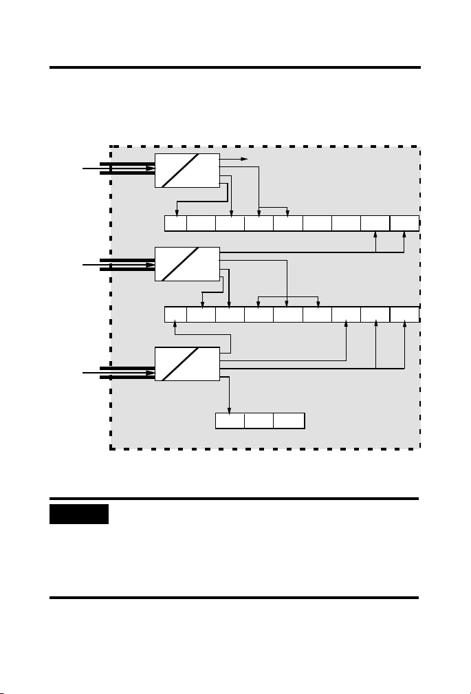
IMPORTANT
IS Pwr
Safe Area
Hazardous Area
1797 power supply
1797 power supply
1797 power supply
ACNR
Spare
IE8 OE8 IRT8 Spare Spare IJ2 IJ2
ACNR OB4 OB4D IBN16 IBN16 IBN16 IE8 IRT8 OE8
RPA RPFM RPFM
IS 1797 I/O
IS 1797 I/O
IS 1797 Fiber Hub
IS Pwr
IS Pwr
IS Pwr
IS Pwr
IS Pwr
IS Pwr
IS Pwr
IS Pwr
IS Pwr
IS Pwr
IS Pwr
EEx d/e
EEx ib
41306
Unsafe
Power
Entrance
Spare
Unsafe
Power
Entrance
Unsafe
Power
Entrance
EEx d/e
EEx ib
EEx d/e
EEx ib
FLEX Ex 85…253V ac In/Quad-Ex dc Out Power Supply 5
The total number of power supplies needed depends on the modules used
and the total system configuration. The following illustration shows how this
example may be configured.
Even though modules may be supplied with power from the same
power-supply output channel, galvanic isolation in the module
provides module-to-module galvanic isolation. Depending upon
the module type, galvanic isolation (channel-to-channel within the
module) may or may not be provided. See the module’s
specifications for more information.
Publication
1797-5.33 - April 2007
Page 6

6 FLEX Ex 85…253V ac In/Quad-Ex dc Out Power Supply
ATTENTION
41307
Make certain that you only connect intrinsically-safe power supplies to other
intrinsically-safe system modules or adapters to maintain the integrity of the
intrinsically-safe backplane.
Installation in Zone 1, 22
The 1797-PS1E Series B power supply has a protection factor of IP65. Refer
to the specifications table for the IS module type.
The power supply cannot be used in an intrinsically safe
environment after its outputs have been exposed to nonintrinsically
safe signals.
Application
When installing, commissioning, operating, and maintaining devices or device
components of the FLEX Ex system as intrinsically-safe electrical apparatus
in potentially explosive atmospheres according to EN 50020, you must heed
the EC- type examination certificate and the applicable national and local
construction, installation, and operating regulations.
Zone 1
The Power Supply unit can be located in Zone 1. The permissible ambient
temperature of -20…70 °C must not be exceeded.
Zone 22
The housing type of the power supply is applicable for use in Zone 22. It
corresponds with the category 3D acc. to directive 94/9 EC and is marked
with a type label accordingly.
Publication
1797-5.33 - April 2007
Page 7

FLEX Ex 85…253V ac In/Quad-Ex dc Out Power Supply 7
Installation and Commissioning
The power supply unit can be located in Zones 1, 2, and 22 as stated on its
label. The output circuits are according to the ignition protection class EEx ib
and can be installed in Zones 1, 2, and 22. When installing, you must heed the
EC- type examination certificate (especially the special conditions) and the
applicable national and local construction, installation, and operating
regulations.
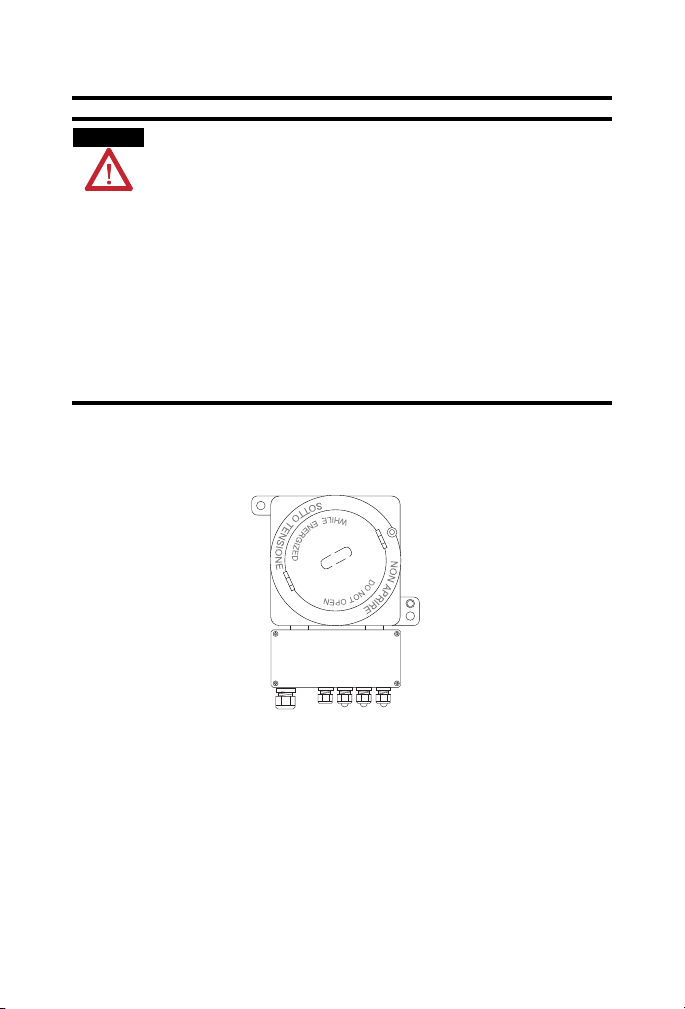
The housing (EEx d) must not be opened (screw cover). Connections are
the EEx e terminal box.
made in
Install the Power feed lines only in the deenergized state. Also follow the
rmation on the type label, respectively the covers of the terminals.
info
You can connect and disconnect the intrinsically-safe output terminals during
erati
on.
op
All unused cable glands must be covered by appropriate prototype tested
EEx e lead seals to keep the requirement of IP54.
he cover installed on the nonintrinsically-safe screw terminals
T
n
(IP30) may only be removed in the dee
after working on these terminals.
Before closing the cover of the EEx e wiring box, inspect the seal for any
gns of damage. In case of damage, the seal must be replaced by a new seal
si
that is identical to the damaged seal.
The power supply housing contains two flanges, which can be connected to a
a
ll or other structural part by means of fixing screws. Select fixing screws
w
that ensure secure fixing of the power supply. Consider the condition of
vibration of the power supply when making this selection.
On the EEx d housing there is an earthing screw. This screw must be
nne
cted to Earth with a conductor having a minimum of 4 mm
co
area. The connection has to be protected against self opening and corrosion.
Corrosion protection can be achieved by using tinned terminal ends.
Before opening the EEx e terminal box (for example, for maintenance
r
poses), it must be cleaned of all dust particles to ensure that no dust can
pu
enter the box.
ergized state and must be remounted
2
(0.006 in.2)
Publication
1797-5.33 - April 2007
Page 8

8 FLEX Ex 85…253V ac In/Quad-Ex dc Out Power Supply
IMPORTANT
ATTENTION
Electrostatic Charge
Protect the system against electrostatic charge. Post a sign near this module.
Attention! Avoid electrostatic charge.
A TENÇÃO! PREVENIR CONTRA O ACÚMULO DE
For your convenience, a sign that can be cut out and posted is included on the
last pag
CARGA ELETROSTÁTICA
e of these installation instructions.
Outputs
When using an intrinsically-safe electrical apparatus according to EN50020,
the European directives and regulations must be followed.
The channels in the power supply are electrically connected to each other and
e a common +V line.
hav
You cannot interconnect lines because of the intrinsic safety
requirements.
Mount the 1797-PS1E Power Supply
Follow these directions to properly install the 1797-PS1E power supply. Refer
to Installation and Commissioning, page 7, for important precautions and
considerations.
Use star washers and nuts to make sure you have a good electrical
connection. Scrape the paint off the back panel in those areas where
grounding bolts will be located.
1. Remove the screws on the cover of the power supply EEx e terminal
ox to access the input and output terminals.
b
2. Thread the blue IS-safe output power wiring through the blue IS
mpression seals.
co
Publication
1797-5.33 - April 2007
Page 9

FLEX Ex 85…253V ac In/Quad-Ex dc Out Power Supply 9
ATTENTION
3. Connect the blue IS-safe output power wiring to the output terminals
making sure all connections are tight.
These power supply outputs provide the input power to the FLEX Ex
s.
module
4. Thread the hazardous incoming power wiring through the black
mpression seals.
co
5. Connect the hazardous incoming power wiring to
the input terminals
making sure all connections are tight.
You can daisy chain the hazardous incoming power wiring to further
pplies to simplify system wiring.
su
Keep hazardous and IS-safe wiring separated in a suitable
fashion. Do not leave long, excess wiring that could bridge
between the hazardous and safe areas.
6. Replace the lid of the EEx e terminal box.
7. Screw the lid back into place making sure all of the screws are tight.
Publication
1797-5.33 - April 2007
Page 10

10 FLEX Ex 85…253V ac In/Quad-Ex dc Out Power Supply
Vin
Vout
Chassis GND
IS Isolation
Hazardous to IS
-V
+V
Out 1
-V
+V
Out 2
-V
+V
Out 3
41315
IS Limiters
Voltage and Current
-V
+V
Out 4
ac
Type of Power Input
IS Power Output
1
4
Daisy-chaining
+V, -V
You can use the daisy chain configuration if the
total module power draw is < 8.5 W. Otherwise,
power is connected to individual modules.
Combination
Wiring when total module current
power is greater than 8.5 W.
41316
<8.5 W
+V, -V
Other variations are possible depend ing
upon individual module power.
<8.5 W
+V, -V
1797-PS1E
Hazardous
Incoming
Power
IS-safe
Output Power
Keep Wires Separate
Customer Connections
Typical Wiring Configurations
Publication
1797-5.33 - April 2007
Page 11

FLEX Ex 85…253V ac In/Quad-Ex dc Out Power Supply 11
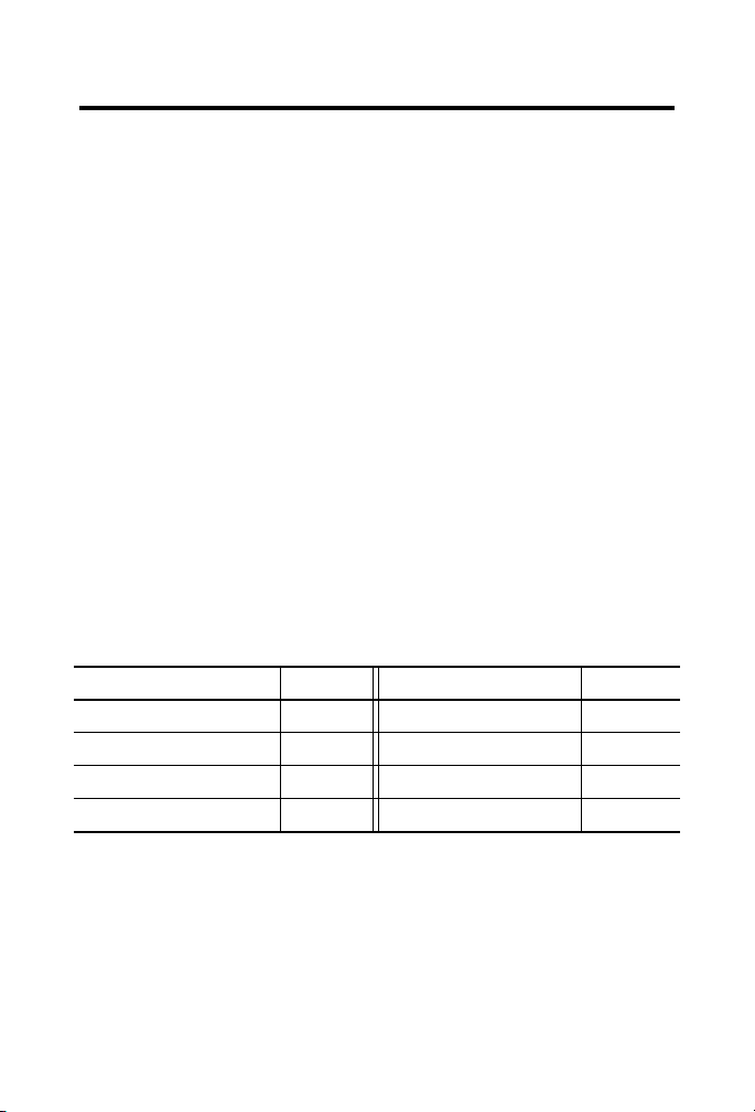
41298A
mm (in.)
218 (8.58)
174 (6.85)
174
(6.85)
280
(11)
Mounting Dimensions
149
(5.87)
10 (0.39) 2 holes
Chassis Ground
194 (7.64)
Height
140 (5.51)
42489
10 11 12 13 14 15 16 17
1245
Chassis
GND
Vout
+V -V +V -V +V -V +V -V
Out 1 Out 2 Out 3 Out 4
Terminal Base Assignments
Vin
European AC Power Input IS Power Output
1797-PS1E Mounting Dimensions and Terminal Base Assignments
Repair
The power supply is not field-repairable. Any attempt to repair this power
supply will void the warranty and IS certification. If repair is necessary, return
this power supply to the factory.
Publication
1797-5.33 - April 2007
Page 12

12 FLEX Ex 85…253V ac In/Quad-Ex dc Out Power Supply
Specifications
Table 1 FLEX Ex Power Supply - 1797-PS1E
Attribute
Zone 1 II 2G EEx de [ib] IIC T4 (DMT 02 ATEX E253 X)
Zone 22 II 3D IP54 T90C
Input connectors 85…253V ac, Um = 253V ac
Voltage range 85…253V ac
Input frequency 47…63 Hz
Current consumption 0.9 A
Ripple N/A
Input power entrance Increased safety
Output connectors Terminals 10…17
Output power 4 x 8.5 W
Inset voltage range 85…253V ac
Voltage U
O
Current I
O
(IIC) <500 nF
C
o
L
(IIC) <8 µH
o
Output cable resistance max
ctions)
(both dire
Isolation path
Input power to output power
Output to output
Input power 55 W
Power dissipation 21 W
Thermal dissipation 71.67 BTU/hr
Conductors wire size
Dimensions (HxWxD) approx. 140 x 174 x 280 mm
Protections class IP 65/NEMA 7B
Weight (approx. 7.7 kg (17 lb)
Valu e
Terminals 1, 2, 4, 5 (earth symbol)
<9.5V
<1 A
<0.1 Ω
Galvanic to DIN EN50020
None
2
(12 gauge) max wire rated for 100 °C (212 °F) or higher
4 mm
1.2 mm (3/64 in.) insulation max
(5.51 x 6.9 x 11.0 in.)
Publication
1797-5.33 - April 2007
Page 13

FLEX Ex 85…253V ac In/Quad-Ex dc Out Power Supply 13
Table 2 Environmental Specifications
Attribute
Temperature, operating IEC 60068-2-1 (Test Ad, Operating Cold),
Temperature, storage IEC 60068-2-1 (Test Ab, Unpackaged Nonoperating Cold),
Relative humidity IEC 60068-2-30 (Test Db, Unpackaged Nonoperating Damp
Shock
Vibration IEC60068-2-6 (Test Fc, Operating):
Emissions CISPR 11
Operating
Nonoperating
Valu e
IEC 60068-2-2 (Test Bd, Operating Dry Heat),
IEC 60068-2-14 (Test Nb, Operating Thermal Shock):
-20…70 °C (-4…158 °F)
IEC 60068-2-2 (Test Bb, Unpackaged Nonoperating Dry Heat)
-40…85 °C (-40…185 °F)
Heat):
5…95% noncondensing
IEC60068-2-27 (Test Ea, Unpackaged shock):
15 g
15 g
2 g @ 10…500 Hz
Radiated, Class A
Conducted, Class B
Publication
1797-5.33 - April 2007
Page 14

14 FLEX Ex 85…253V ac In/Quad-Ex dc Out Power Supply
Table 3 Certifications
Certifications
product is marked)
CE
EE
(when
(1)
Value
European Union 89/336/EEC EMC Directive, co
with:
EN 61000-6-4; Industrial Emissions
EN 61326; Meas./Control/Lab., Industrial Requirements
EN 61000-6-2; Industrial Immunity
EN 50082-2; Industrial Immunity
European Union 73/23/EEC LVD Directive,
compliant with:
EN 50178; Electronic Equipment for use in Power
Installations
European Union 94/9/EC ATEX Directive, compliant with:
EN 50014; Potentially Explosive Atmospheres,
General Requirements
EN 50018; Potentially Explosive Atmospheres, Protection “d”
EN 50019; Potentially Explosive Atmospheres, Protection “e”
EN 50020; Potentially Explosive
Atmospheres, Protection “i”
mpliant
EN 50281-1-1; Electrical apparatus protected by enclosure
C-Tick
INMETRO
(1)
See the Product Certification link at www.ab.com for Declarations of Conformity, Certificates, and other
certification details.
Australian Radiocommunications Act, compliant with:
AS/NZS CISPR11; Industrial Emissions
BR-Ex de [ib] IIC T4
Certificate number 05/UL-BRAE-0018X
Publication
1797-5.33 - April 2007
Page 15

Ferrite Beads
Pass all IS power-supply
output wires through the
ferrite bead before
connecting the cable to the
power supply.
30889
Attention: Avoid electrostatic charge.
ATENÇÃO! PREVENIR CONTRA O ACÚMULO
DE CARGA ELETROSTÁTICA
FLEX Ex 85…253V ac In/Quad-Ex dc Out Power Supply 15
Publication
1797-5.33 - April 2007
Page 16

Rockwell Automation Support
Rockwell Automation provides technical information on the Web to assist you in using
our products. At http://support.rockwellautomation.com
manuals, a knowledge base of FAQs, technical and application notes, sample code and
links to software service packs, and a MySupport feature that you can customize to
make the best use of these tools.
For an additional level of technical phone support for installation, configuration and
troubleshooting, we offer TechConnect Support programs. For more information,
contact your local distributor or Rockwell Automation representative, or visit
http://support.rockwellautomation.com
.
Installation Assistance
If you experience a problem with a hardware module within the first 24 hours of
installation, please review the information that's contained in this manual. You can also
contact a special Customer Support number for initial help in getting your module up
and running:
United States 1.440.646.3223 Monday – Friday, 8am – 5pm EST
Outside United States Please contact your local Rockwell Automation representative for any
technical support issues.
New Product Satisfaction Return
Rockwell tests all of our products to ensure that they are fully operational when shipped
from the manufacturing facility. However, if your product is not functioning and needs
to be returned:
United States Contact your distributor. You must provide a Customer Support case number
Outside United States Please contact your local Rockwell Automation representative for return
(see phone number above to obtain one) to your distributor in order to
complete the return process.
procedure.
, you can find technical
Allen-Bradley, Rockwell Automation, TechConnect, and FLEX Ex are trademarks of Rockwell Automation, Inc.
Trademarks not belonging to Rockwell Automation are property of their respective companies.
Publication 1797-5.33 - April 2007 PN 953157-42
Supersedes Publication 1797-5.33 - February 2006 Copyright © 2007 Rockwell Automation, Inc. All rights reserved. Printed in the U.S.A.
 Loading...