

Page 1

Installation Instructions
FLEX Ex I/O 24V DC 4 Non-Isolated Source
Output Module
Catalog Number 1797-OB4D
Top ic Page
Important User Information 2
Installation in Zone 1 5
Installation on Zone 22 5
Module Installation 3
Outputs 8
Wire to a 1797-TB3 or 1797-TB3S Terminal Base Unit 9
Ground the Module 11
Indicators 11
Memory Mapping 12
Field Descriptions 12
Repair 14
Specifications 15
Cooperative Operation of the ControlNet Ex Adapter and FLEX Ex
Output Modules
FLEX Ex Output Module Operation 18
Entity Parameters 19
Output Voltage versus Current Capability 29
17
Publication 1797-5.6 - June 2011
Page 2
2 FLEX Ex I/O 24V DC 4 Non-Isolated Source Output Module
WARNING
IMPORTANT
ATTENTION
SHOCK HAZARD
Important User Information
Solid state equipment has operational characteristics differing from those of electromechanical
equipment. Safety Guidelines for the Application, Installation and Maintenance of Solid State Controls
(Publication SGI-1.1
http://www.literature.rockwellautomation.com
state equipment and hard-wired electromechanical devices. Because of this difference, and also because
of the wide variety of uses for solid state equipment, all persons responsible for applying this equipment
must satisfy themselves that each intended application of this equipment is acceptable.
In no event will Rockwell Automation, Inc. be responsible or liable for indirect or consequential damages
resulting from the use or application of this equipment.
The examples and diagrams in this manual are included solely for illustrative purposes. Because of the
many variables and requirements associated with any particular installation, Rockwell Automation, Inc.
cannot assume responsibility or liability for actual use based on the examples and diagrams.
No patent liability is assumed by Rockwell Automation, Inc. with respect to use of information, circuits,
equipment, or software described in this manual.
Reproduction of the contents of this manual, in whole or in part, without written permission of Rockwell
Automation, Inc., is prohibited.
Throughout this manual we use notes to make you aware of safety considerations.
available from your local Rockwell Automation sales office or online at
Identifies information about practices or circumstances that can cause an explosion in a
hazardous environment, which may lead to personal injury or death, property damage, or
economic loss.
Identifies information that is critical for successful application and understanding of the
product.
) describes some important differences between solid
Publication
Identifies information about practices or circumstances that can lead to personal injury or
death, property damage, or economic loss. Attentions help you identify a hazard, avoid a
hazard, and recognize the consequence
Labels may be located on or inside the equipment to alert people that dangerous voltage
may be present.
1797-5.6 - June 2011
Page 3
FLEX Ex I/O 24V DC 4 Non-Isolated Source Output Module 3
3
5
1
8
7
6
2
Label here or under here
4
40231
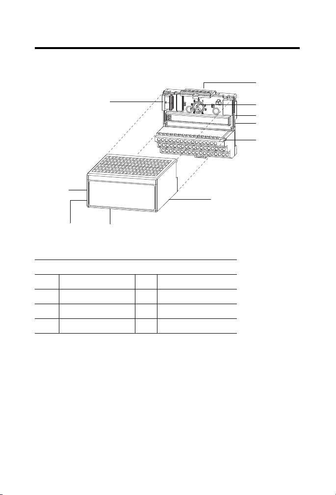
Module Installation
Component identification
1 FlexBus connector 5 Terminal base unit
2 Latching mechanism 6 Alignment groove
3 Keyswitch 7 Alignment bar
4 Cap plug 8 Module
Publication
1797-5.6 - June 2011
Page 4

4 FLEX Ex I/O 24V DC 4 Non-Isolated Source Output Module
ATTENTION
Install the Module
This equipment is considered Group 1, Class A industrial equipment according
to IEC/CISPR Publication 11. Without appropriate precautions, there may be
potential difficulties ensuring electromagnetic compatibility in other
environments due to conducted as well as radiated disturbance.
This equipment is supplied as open-type equipment. It must be mounted within an
enclosure that is suitably designed for those specific environmental conditions that
will be present and appropriately designed to prevent personal injury resulting
from accessibility to live parts. The interior of the enclosure must be accessible
only by the use of a tool. Subsequent sections of this publication may contain
additional information regarding specific enclosure type ratings that are required
to comply with certain product safety certifications.
This module must be used with a 1797-TB3 or 1797-TB3S intrinsically safe
terminal base unit.
otate keyswitch (3) on terminal base unit (5) clockwise to position 7
1. R
as required for this type of module.
Do not change the position of the keyswitch after wiring the
minal base unit
ter
e certain the FlexBus connector (1) is pushed all the way to the
2. Mak
left to connect with the neighboring terminal base/adapter.
You cannot install the module unless the connector is fully
d.
extende
e sure the pins on the bottom of the module are straight so they
3. Mak
will align properly with the connector in the terminal base unit.
osition the module (8) with its alignment bar (7) aligned with the
4. P
groove (6) on the terminal base.
5. Press f
irmly and evenly to seat the module in the terminal base unit.
The module is seated when the latching mechanism (2) is locked into
the module.
Publication
1797-5.6 - June 2011
Page 5
FLEX Ex I/O 24V DC 4 Non-Isolated Source Output Module 5
WARNING
41307
6. Make certain that you only connect terminal base units to other
intrinsically safe system modules or adapters to maintain the integrity
of the intrinsically-safe backplane.
emove the cap plug (4) and attach another intrinsically safe terminal
7. R
base unit to the right of this terminal base unit if required.
Installation in Zone 1
This module must not be exposed to the environment and must have a
suitable metal enclosure. It has a protection factor of IP20.
This module cannot be used in an intrinsically safe environment after it has
been exposed to nonintrinsically safe signals.
Installation on Zone 22
When the module is installed in Zone 22, the following cabinets must be used:
IVK-ISRPI-V16LC; IVK-ISRPI-V8HYW; or IVK-ISRPI-V8LC. These
cabinets can be purchased from:
Pepperl+Fuchs GmbH
Lilienthalstrasse 200
68307 Mannheim, Germany
Attn: PA Sales Dept.
Kirsten Becker
Telephone +49 776 1298
www.pepperl-fuchs.com
Publication
1797-5.6 - June 2011
Page 6

6 FLEX Ex I/O 24V DC 4 Non-Isolated Source Output Module
The IS-RPI cabinets (type IVK2-ISRPI-V8LC, IVK2-ISRPI-V8HYW, or
IVK2-ISPRI-V16LC) ensures the basic protection for the intrinsically safe
apparatus of the FLEX Ex system for use in Zone 22. It corresponds with
category 3D according to RL 94/9 EG and with the type label marked with
the following information:
Pepperl+Fuchs GmbH
68307 Mannheim
IVK2-ISRPI-V8LC (or IVK2-ISRPI-V8HYW or
IVK2-ISRPI-V16LC)
II 3 D Ex tD A22 IP54 T70 °C X
CE
Serial (manufacturin
Model
g) number
Electrostatic Charge
Protect the system against electrostatic charge. Post a sign near this module:
WARNING Avoid electrostatic charging.
ADVERTÊNCIA! PREVENIR CONTRA O ACÚMULO DE CARGA
ELETROSTÁTICA.
For your convenience, a sign that can be cut out is included in this installation
instr
uction.
Publication
1797-5.6 - June 2011
Page 7

FLEX Ex I/O 24V DC 4 Non-Isolated Source Output Module 7
WARNING
Removal and Insertion Under Power
These modules are designed so you can remove and insert them under
power. However, take special care when removing or inserting modules in an
active process. I/O attached to any module being removed or inserted can
change states due to its input/output signal changing conditions.
If you insert or remove the terminal base while backplane power is on, an
electrical arc can occur. This could cause an explosion in hazardous location
installations.
Be sure that power is removed or the area is nonhazardous before proceeding.
European Communities (EC) Directive Compliance
If this product has the CE mark it is approved for installation within the
European Union and EEA regions. It has been designed and tested to meet
the following directives.
EMC Directive
These products are tested to meet the Council Directive 2004/108/EC by
applying the following standards:
• EN 6100
Generic Standard for Industrial Environments (Class A)
• EN 6100
Generic Standards - Immunity for Industrial Environments
• EN6132
Measurement, Control, and Laboratory Use - Industrial EMC
Requirements
0-6-4:2007, Electromagnetic Compatibility (EMC) - Part 6-4:
0-6-2:2005, Electromagnetic Compatibility (EMC) - Part 6-2:
6-1:2006 (Industrial), Electrical Equipment For
ATEX Directive
These products are tested in conjunction with associated I/O modules to
meet the Council Directive 94/9/EC (ATEX) Equipment and Protective
Systems Intended for Use in Potentially Explosive Atmospheres by applying
the following standards:
Publication
1797-5.6 - June 2011
Page 8
8 FLEX Ex I/O 24V DC 4 Non-Isolated Source Output Module
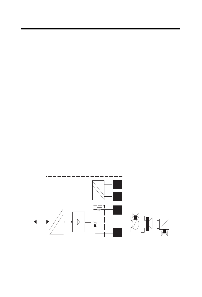
FlexBus
Bus
uC
+V
-V
+
-
Power
supply
Valve
Audible
alarm
Solenoid
40069
• EN60079-11:2007, Explosive atmospheres - Part 11 : equipment
protection by intrinsic safety "i"
• EN6007
9-0:2006, Electrical apparatus for explosive gas atmospheres -
Part 0 : general requirements
• EN 60
079-26 : 2004, Electrical apparatus for explosive gas
atmospheres - Part 26 : construction, test and marking of Group II
Category 1 G electrical apparatus
• EN6124
1-0 : 2006, Electrical apparatus for use in the presence of
combustible dust - Part 0: General requirements
• EN6124
1-11:2006, Electrical apparatus for use in the presence of
combustible dust – Part 11: Protection by intrinsic safety 'iD'
Outputs
Each output can operate a digital field device.
Do not apply any nonintrinsically safe signals to this module.
When using an intrinsically safe electrical apparatus according to EN50020,
the European Community directives and regulations must be followed.
The channels in this module are electrically connected to each other.
Publication
1797-5.6 - June 2011
Page 9
FLEX Ex I/O 24V DC 4 Non-Isolated Source Output Module 9
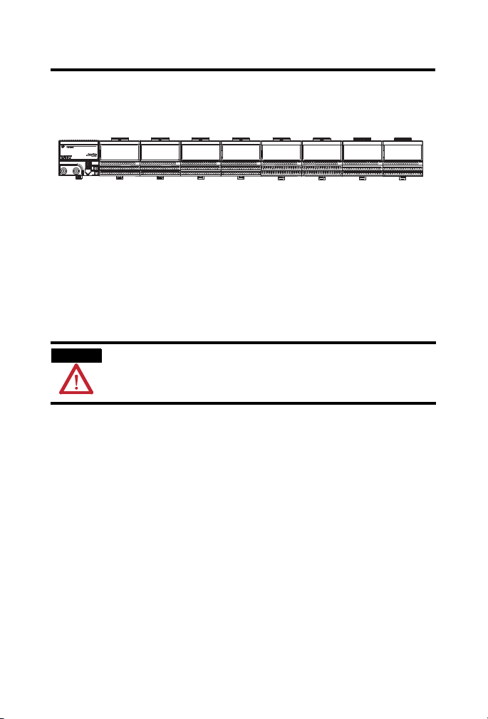
No connections allowed to terminals 2, 3, 6, 7, 10, 11, 14, 15, 17 to 32, 36, 37, 38, 39,
46, 47, 48, 49.
40068A
Row A
Row B
Row C
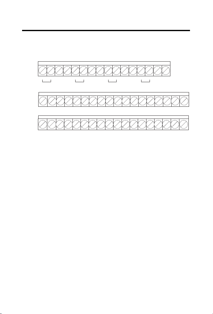
Wire to a 1797-TB3 or 1797-TB3S Terminal Base Unit
Connect wiring to the terminal base as shown below.
0 1 2 3 4 5 6 7 8 9 10 11 12 13 14 15
_
+
CH 0 CH 1 CH 2 CH 3
16 17 18 19 20 21 22 23 24 25 26 27 28 29 30 31
34 35 36 37 38 39 40 41 42 43 44 45 46 47 48 49
nnect the individual output wiring to (+) terminals (0, 4, 8, 12) on
1. Co
_
+
_
+
_
+
the 0…15 row (A) as indicated in the table below.
nnect the associated output to the corresponding (-) terminal (1, 5,
2. Co
9, 13) on the 0…15 row (A) for each output as indicated in the table
below.
nect +V DC power to terminal 34 on the 34…51 row (C).
3. Con
4. Con
nect -V to terminal 35 on the 34…51 row (C).
32 33
50 51
+V -V+V -V
Publication
1797-5.6 - June 2011
Page 10

10 FLEX Ex I/O 24V DC 4 Non-Isolated Source Output Module
WARNING
ATTENTION
Make certain that you power this module with an intrinsically safe power
supply. Do not exceed the values listed in the specifications for this module.
If you connect or disconnect wiring while the field-side power is on, an
electrical arc can occur. This could cause an explosion in hazardous location
installations. Be sure that power is removed or the area is nonhazardous
before proceeding.
5. If continuing power to the next terminal base unit, connect a jumper
from terminal 50 (+V) on this base unit to terminal 34 on the next
base unit.
ntinuing common to the next terminal base unit, connect a
6. If co
jumper from terminal 51 (-V) on this base unit to terminal 35 on the
next base unit.
Module Wire Connections
Output Output + Output -
Output 0 A-0 A-1
Output 1 A-4 A-5
Output 2 A-8 A-9
Output 3 A-12 A-13
+V Terminals C-34 and C-50
-V Terminals C-35 and C-51
Publication
Do not use the unused terminals on this terminal base unit. Using
these terminals as supporting terminals can result in damage to the
module or unintended operation of your system, or both.
1797-5.6 - June 2011
Page 11

FLEX Ex I/O 24V DC 4 Non-Isolated Source Output Module 11
30820-M
Shield terminating
feed-through
Bus bar
PWR
40067
A = Status indicators
B = Insertable labels for writing individual input designations
C = Power indicator (green indicates power applied to the module)
Ground the Module
All I/O wiring must use shielded wire. Shields must be terminated external to
the module, such as bus bars and shield-terminating feed throughs.
Indicators
1797-OB4D
A B C
Publication
Ex
PWR
1797-5.6 - June 2011
Page 12

12 FLEX Ex I/O 24V DC 4 Non-Isolated Source Output Module
Status Indicators
Indicator Status Description
Yel low Individual input present
Flashing red Channel fault
Solid red Module did not pass power up check
Channel 0 is solid red while power-up check is running
Memory Mapping
Dec
Bit
Oct
Bit
Read 0 OVL 3OVL 2OVL 1OVL 0F3 F2 F1 F0
Write 0 Out
Configuration 1 RA Alarm Filter
Where: OVL = Overload alarm for individual channel
15 14 13 12 11 10 09 08 07 06 05 04 03 02 01 00
17 16 15 14 13 12 11 10 07 06 05 04 03 02 01 00
Enb
F = Fault alarm for individual channel
DA = Detect Alarms, Detection of Output faults (0 = Disable, 1 = Enable)
FS = Fault state (0 is reset and 1 is hold last state)
D = Data, Output data 0 = Off 1 = On
L = Latch alarms (0 = Disable, 1 = Enable)
Out Enb = Output Enable
RA = Reset Alarms (0 = Normal, 1 = Reset)
LDA 3DA 2DA 1DA 0FS 3FS 2FS 1FS 0D3 D2 D1 D0
Ch 0…3
Field Descriptions
Field Description
Fault Alarm 0 = No fault
1 = Wire-off fault or overload
100 Hz (10 ms) filter is integrated
A wire-off fault or overload can be detected using this single bit.
Note:
Publication
1797-5.6 - June 2011
Page 13

FLEX Ex I/O 24V DC 4 Non-Isolated Source Output Module 13
Field Descriptions
Overload Alarm 0 = No fault
Data Output data
Fault State 0 = Output goes to 0 during fault
Detect Alarms These bits can be used to activate/deactivate
1 = Output channel overloaded
(Load resistance range 30…5000 Ω)
100 Hz (10 ms) filter is integrated
0 = Off
1 = On
Default = 0
1 = Hold last state
Default = 0
overload monitoring of the outputs for each channel.
0 = Wire-off detection/overload monitorin
1 = Wire-off detection/overload monitorin
g deactivated
g activated
wire-off detection and
Note: Leakag
detection is activated. The normal load range is defined as 30
this range, no faults will occur. Wire off is assured to be reported for loads
> 75
Latch Alarms
Outputs Enable 0 = Outputs disabled
This bit defines for all channels, whether, in the event of a wire off or overload
fault, the corresponding fault bit (Overload Alarm, Fault Alarm) remains set
until the Reset Alarms bit in the configuration data word is reset by the user.
This ensures that a fault message is sent to the control system in the event of
a fault that is short in duration. The alarms should be latched if the Latch
Alarms bit is 1 and the outputs go to 0 state until the Reset Alarm occurs.
0 = Alarms and outputs are automatically reset
1 = Alarms and outputs are blocked and must be reset by setting the bit
Re
set Alarms through the user program.
Default = 0
1 = Outputs enabled
Default = 0
This bit must be set to 1 by the program for normal operation of the
outpu
e current will be present when output is at 0 state if Wire Off
kΩ.
It does not matter if the output is OFF or ON.
ts. When set to 0 the outputs will follow the Fault State status.
Publication
Ω…5
kΩ.
In
1797-5.6 - June 2011
Page 14

14 FLEX Ex I/O 24V DC 4 Non-Isolated Source Output Module
Value Binary Time constant
000 0.25 ms (Hardware)
001 0.5 ms
010 1 ms
011 2 ms
100 4 ms
101 8 ms
110 16 ms
111 32 ms
Field Descriptions
Alarm Filter These 3 bits are used to set the time constant of the fault/overload alarm
filter for channels 0…3.
Default = 0
Reset Alarms With this bit, wire off/overload fau
the outputs cancelled. See Latch Alarms (LA). To reset the wire
off/overload faults set the RA bit to 1 and back to 0. The reset will not
occur until a 0 > 1 > 0 transition occurs.
RSLogix 5000 Software Tip: The Reset Alarms bit is found in the Module
nfiguration word. Program a Module Reconfigure typed MSG to set and
Co
then clear the RA bit.
0 = Normal
Repair
This module is not field-repairable. Any attempt to open this module will void
the warranty and IS certification. If repair is necessary, return this module to
the factory.
Publication
1 = Reset
Default: 0
1797-5.6 - June 2011
lts are reset and the latch condition of
Page 15

FLEX Ex I/O 24V DC 4 Non-Isolated Source Output Module 15
Specifications
General
Attribute Valu e
Number of outputs 4, nonisolated, sourcing
IS output type Ex ia IIB/IIC T4,
AEx ia IIC T4,
Class I, II, III Division 1 Groups
IS module type Ex ib IIB/IIC T4,
AEx ib IIC T4,
Class I Division 1 Groups A…D T4
V-I Characteristics Refer to Output Voltage versus Current Capability on
page 29
Load range 30…5000 Ω
Fault detection Fault bits in data table and LED (per channel)
blinking red (1 Hz)
Electronic protection Lead break, overload, short circuit
Maximum output delay times
OFF to ON
ON to OFF
<1.2 ms
<1.2 ms
Indicators 4 yellow status indicators
4 red fault indicators
1 green module power indicator
Output (intrinsically safe)
(16 pin male and female
FlexBus connector)
< 5.8V DC
U
i
I
< 400 mA
i
L
= Negligible
i
C
< 1.35 μF
i
A, B, C, D, E, F, G T4
Isolation path
Output to power supply
Output to FlexBus
Power supply to FlexBus
Output to output
Isolation type
Galvanic to DIN EN 60079-11
Galvanic to DIN EN 60079-11
Galvanic to DIN EN 60079-11
None
Publication
1797-5.6 - June 2011
Page 16

16 FLEX Ex I/O 24V DC 4 Non-Isolated Source Output Module
General
Power supply
(+V, -V Intrinsically safe)
Module field-side
wer consumption
po
Ui < 9.5V DC
I
< 1 A
i
L
= Negligible
i
C
= Negligible
i
7.5 W
Power dissipation 5 W
Thermal dissipation 17.07 BTU/hr
Module location 1797-TB3 or 1797-TB3S Terminal base unit
Conductors wire size, max
2
(12 gauge) stranded
4 mm
1.2 mm (3/64 in.) insulation
Dimensions
HxWxD
46 x 94 x 75 mm
(1.8 x 3.7 x 2.95 in.)
Weight, approx. 200 g (7.05 oz.)
Keyswitch position 7
Environmental Specification
Attribute Value
Temperature, operating
Temperature, storage
Relative humidity 5…95% noncondensing
Shock, operating Tested to 15 g peak acceleration, 11(+1) ms pulse width
Shock, nonoperating Tested to 15 g peak acceleration, 11(+1) ms pulse width
Vibration Tested 2 g @ 10…500 Hz per IEC68-2-6
-20…+70
-40…+85
°
C (-4…+158 °F)
°
C (-40…+185 °F)
Publication
1797-5.6 - June 2011
Page 17

Certifications
FLEX Ex I/O 24V DC 4 Non-Isolated Source Output Module 17
Certifications when product
is marked
CENELEC II (1) 2G Ex ib[ia] IIC T4
UL, C-UL Class I, Groups A, B, C and D; Class
FM Intrinsically safe Class I, Div
INMETRO BR-Ex ia/ib IIB/IIC T4
IECEx [Zone 0] Ex ib[ia] IIC T4
(1)
(1)
See the Product Certification link at http://www.ab.com for Declaration of Conformity, Certificates,
and other certification details.
Valu e
I (1) D [Ex iaD]
I
G; Class III Hazardous Locations
Class I, Zone 1, AEx ib[ia] IIC T4.
Associated Apparatus with instrincally safe
connections Class I, II, III, Div 1, Groups A-G.
Intrinsically safe Class I, Zone 1, AEx ib[ia] IIC T4.
[Ex iaD]
II, Groups E, F and
1, Groups A, B, C, D, T4.
Cooperative Operation of the ControlNet Ex Adapter and FLEX Ex Output Modules
The ControlNet Ex adapter (1797-ACNR15) combined with FLEX Ex
output module provides a two-tier fault state mechanism. It is important to
consider and understand the operation of this mechanism when designing
your system.
Two sets of programmable fault states are
and output module. This two-tier method is meant to give you a wider fault
coverage compared with normal methods.
available, one each in the adapter
Publication
1797-5.6 - June 2011
Page 18

18 FLEX Ex I/O 24V DC 4 Non-Isolated Source Output Module
Adapter Operation
Network Communication Monitoring
The adapter is the primary monitor of network activity. If it detects loss of
network communication, it can be programmed to:
• continue writing the last valid receiv
state).
• apply local module safe states.
ed data to the module (hold last
(1)
• write a programmable fault state value to the module, depending upon
(2)
the module type.
This mechanism primarily targets fault behavior for loss of network
communication.
Program Mode Behavior
The adapter also monitors the state of the controlling processor or scanner.
Two states can be detected: Run mode and Program mode (idle).
When Program mode is detected, the adapter can be configured to:
ntinue writing the last valid received data to the module (hold last
• co
state).
• appl
y local module safe states to zero.
(1)
• write a programmable fault state value to the module, depending upon
the module type.
(2)
FLEX Ex Output Module Operation
The following describes the output module operation.
(1)
This selection is shown as Reset Outputs in RSNetWorx software, but its action is Apply Local Module
Safe States.
(2)
This option is only available in some adapters.
Publication
1797-5.6 - June 2011
Page 19

FLEX Ex I/O 24V DC 4 Non-Isolated Source Output Module 19
Flexbus Communication Monitoring
The module monitors FlexBus communication activity and the state of its
Output Enable bit. If it detects loss of FlexBus communication activity or the
Output Enable bit transitioning to 0, it can be programmed to:
ntinue writing the last valid received data to the outputs (hold last
• co
state).
• reset the
• write th
the module type.
This mechanism primarily targets fault behavior for loss of backplane
mmunication.
co
outputs.
e local module fault state value to the output, depending upon
Power-up State Behavior
The system and modules use the Output Enable bit at system power-up. The
power-up state of the Output Enable bit is 0 and must be transitioned to 1
through application program control to initialize activity of a module’s
outputs.
Before the Output Enable bit is transition
Once the initial power-up and application-program control transitions the
Output Enable bit to 1, and module output activity begins, subsequent
transitions of the Output Enable bit by any source will cause the output
module to apply the local module fault state.
ed to 1, module outputs remain off.
Entity Parameters
CE, CENELEC I/O Entity Parameters
Signal output (+ to -) for ch 0…ch 3 (terminals: 0 and 1; 4 and 5; 8 and 9; 12
and 13).
Publication
1797-5.6 - June 2011
Page 20

20 FLEX Ex I/O 24V DC 4 Non-Isolated Source Output Module
Entity Parameters
1797-OB4D
= 27.4V
U
o
I
= 110 mA
o
If concentrated capacitance
or inductance are available,
and/
use the following values.
Protection Group Allowed
Capacitance
Ex ia IIB 677 nF 8 mH
IIC 87 nF 2 mH
Ex ia IIB 150 nF 5 mH
IIC 30 nF 2 mH
Allowed
Inductance
The values of Lo and Co listed in the table above are allowed if one of the
following conditions is met:
• The total L
of the external circuit (excluding the cable) is < 1% of the
i
Lo value or
• The total C
of the external circuit (excluding the cable) is < 1% of the
i
Co value.
The values of L
and Co listed in the table above shall be reduced to 50%
o
when both of the following conditions are met:
• The total L
value and
L
o
• The total C
value.
C
o
The reduced capacitance of the external circuit (including cable) shall
Note:
of the external circuit (excluding the cable) is ≥ 1% of the
i
of the external circuit (excluding the cable) is ≥ 1% of the
i
not be greater than 1µF for IIB and IIA and 600nF for IIC.
UL, C-UL I/O Entity Parameters
If this product has the UL/C-UL mark, it has been designed, evaluated,
tested, and certified to meet the following standards:
• UL 91
Publication
3, 1988, Intrinsically Safe Apparatus and Associated Apparatus
for Use in Class I, II, and III Division 1, Hazardous (Classified)
Locations
1797-5.6 - June 2011
Page 21

FLEX Ex I/O 24V DC 4 Non-Isolated Source Output Module 21
• UL 1203, Explosion-Proof and Dust-Ignition-Proof Electrical
Equipment for Use in Hazardous (Classified) Locations
• UL 22
79, Electrical Equipment for Use in Class I, Zone 0, 1, and 2
Hazardous (Classified) Locations
61010, UL Standard for Safety Electrical Equipment For
• UL
Measurement, Control, and Laboratory Use; Part 1: General
Requirements
• CSA C22.2 No
. 157-92, Intrinsically Safe and Non-Incendive
Equipment for Use in Hazardous Locations
• CSA C22.2 No
. 30-M1986, Explosion-Proof Enclosures for Use in
Class I Hazardous Locations
• CSA-E79
-0-95, Electrical Apparatus for Explosive Gas Atmospheres,
Part 0: General Requirements
• CSA-E79
-11-95, Electrical Apparatus for Explosive Gas
Atmospheres, Part 11: Intrinsic Safety “i”
C22.2 No. 14-95, Industrial Control Equipment
• CSA
Wiring Methods
ring method 1: Each channel is wired separately.
• Wi
ring method 2: Multiple channels in one cable, providing each
• Wi
channel is separated in accordance with the National Electric Code
(NEC) or Canadian Electric Code (CEC).
Wiring Method
Wiring
Me
1 and 2 Any one
Channel Te rm in al s Voc
thod
channel
(fo
r
example,
ch0)
0(+), 1(-) 27.4 110.0 - - A, B, IIC 0.03 2.0
(V)
Isc
(mA)
Vt
(V)
It
(mA)
Groups Ca
C, E, IIB 0.09 8.0
D, F, G, IIA 0.24 16.0
(μF)
La
(mH)
Publication
1797-5.6 - June 2011
Page 22

22 FLEX Ex I/O 24V DC 4 Non-Isolated Source Output Module
IMPORTANT
PWR
FLEX Ex digital
output I/O module
Indicators
Female bus
connection
Field wiring
terminals
Terminal base
Terminal base
key
Male bus
connection
Key position for
terminal base
insertion
42058
Ex
1797-OB4D
PWR
A terminal base may or may not have an I/O module installed.
Publication
1797-5.6 - June 2011
Page 23

FLEX Ex I/O 24V DC 4 Non-Isolated Source Output Module 23
Hazardous (Classified) Location
Class I, Zones 0, 1, & 2 Groups IIC, IIB, IIA
Class I, Div. 1 & 2 Groups A, B, C, D
Class II, Div. 1 & 2 Groups E, F, G
Class III, Div. 1 & 2
Hazardous (Classified) Location
Class I, Zones 1 & 2 Groups IIC, IIB, IIA
Class I, Div. 1 & 2 Groups A, B, C, D
To any intrinsically safe
device or associated
apparatus with Entity
Concept parameters of
V
oc
< 5.8V; Isc < 400 mA.
To any intrinsically safe
device or associated
apparatus with Entity
Concept parameters of
V
oc
< 9.5V; Isc < 1 A.
To any IS device with Entity
Concept parameters of
(V
max
, I
max
, Ci, Li) appropriate
for connection to associated
apparatus with Entity Concept
parameters listed in the table,
Wiring Method.
1797-OB4D
16
Shield connection only
50
51
35
34
V
max
=5.8V
I
max
=400mA
C
i
=1350nF
L
i
=negligible
V
max
=9.5V
I
max
=1A
C
i
=negligible
L
i
=negligible
Male Bus
Connector
33
40
41
42
43
44
45
0 (+)
Female Bus
Connector
1 (-)
ch0
ch1
ch2
ch3
4 (+)
5 (-)
8 (+)
9 (-)
12 (+)
13 (-)
42059
Any Simple Apparatus or I.S.
device with Entity Concept
parameters (V
max
, I
max
, Ci, Li)
appropriate for connection to
associated apparatus with Entity
Concept parameters listed in the
table, Terminal Connections.
Terminal Connections
Ter mi na ls Vt (V) It (mA) Groups Ca (μF) La (μH)
Male bus
5.8 400 A to G 3.0 3.0
connector
The entity concept allows interconnection of intrinsically safe apparatus
with associated apparatus not specifically examined in combination as a
system when the approved values of V
apparatus are less than or equal to V
apparatus and the approved values of C
are greater than C
+ C
i
apparatus. The internal capacitances Ci of the terminal base must be taken
into account to verify the intrinsic safety.
and I
oc
sc
and I
max
max
and La of the associated apparatus
a
respectively for the intrinsically safe
cable
and Li + L
cable
or Vt and It of the associated
of the intrinsically safe
Publication
1797-5.6 - June 2011
Page 24

24 FLEX Ex I/O 24V DC 4 Non-Isolated Source Output Module
The values of Lo and Co listed in the table above are allowed if one of the
following conditions is met:
• The total L
value or
L
o
• The total C
value.
C
o
The values of L
of the external circuit (excluding the cable) is < 1% of the
i
of the external circuit (excluding the cable) is < 1% of the
i
and Co listed in the table above shall be reduced to 50%
o
when both of the following conditions are met:
• The total L
value, and
L
o
• The total C
value.
C
o
Note:
The reduced capacitance of the external circuit (including cable) shall
of the external circuit (excluding the cable) is ≥ 1% of the
i
of the external circuit (excluding the cable) is ≥ 1% of the
i
not be greater than 1µF for IIB and IIA and 600nF for IIC.
Simple apparatus is defined as a device which neither generates nor stores
more than 1.2V, 0.1 A, 20
Wiring methods must be in accordance with the National Electric Code,
μJ, or 25 mW.
ANSI/NFPA 70, Article 504 and 505 or the Canadian Electric Code CSA
C22.1, Part 1, Appendix F. For additional information refer to ANSI/ISA
RP12.6.
This module, 1797-OB4D, must be used with terminal base 1797-TB3 or
1797-TB3S.
Terminals 2, 3, 6, 7, 10, 11, 14, 15, 17 to 32, 36 to 39, and 46 to 49 shall
not be connected.
WARNING: Substitution of components may impair intrinsic safety.
AVERTISSEMENT: La subs
titution de composant peut compromettre la
securite intrinseque.
FM I/O Entity Parameters
If this product has the FM mark, it has been designed, evaluated, tested, and
certified to meet the following standards:
Publication
1797-5.6 - June 2011
Page 25

FLEX Ex I/O 24V DC 4 Non-Isolated Source Output Module 25
• FM C1. No.3600:1998, Electrical Equipment for Use in Hazardous
(Classified) Locations General Requirements
• FM C1
. No.3610:1999, Intrinsically Safe Apparatus and Associated
Apparatus for Use in Class I, II, III Division 1 Hazardous (Classified)
Locations
• FM C1. No
.3615:1989, Explosionproof Electrical Equipment General
Requirements
• FM C1
. No.3810:1989, 1995, Electrical and Electronic Test,
Measuring and Process Control Equipment
• ANSI/NEMA 250
, 1991, Enclosures for Electrical Equipment
Wiring Methods
ring method 1: Each channel is wired separately.
• Wi
• Wiring method 2: Multiple channels in one cable, providing each
channel is separated in accordance with the National Electric Code
(NEC).
Wiring Method
Wiring
Method
1 and 2 Any one
Channel Te rm in al s Voc
(V)
channel
(fo
example,
ch0)
0(+), 1(-) 27.4 110.0 - - A, B 0.105 3.0
r
Isc
(mA)
Vt
(V)
It
Groups Ca
(mA)
C, E 0.315 9.0
D, F, G 0.840 24.0
(μF)
La
(mH)
Publication
1797-5.6 - June 2011
Page 26

26 FLEX Ex I/O 24V DC 4 Non-Isolated Source Output Module
IMPORTANT
PWR
FLEX Ex digital
output I/O module
Indicators
Female bus
connection
Field wiring
terminals
Terminal base
Terminal base
key
Male bus
connection
Key position for
terminal base
insertion
42058
Ex
1797-OB4D
PWR
A terminal base may or may not have an I/O module installed.
Publication
1797-5.6 - June 2011
Page 27

FLEX Ex I/O 24V DC 4 Non-Isolated Source Output Module 27
Hazardous (Classified) Location
Class I, Zones 0, 1, & 2 Groups IIC, IIB, IIA
Class I, Div. 1 & 2 Groups A, B, C, D
Class II, Div. 1 & 2 Groups E, F, G
Class III, Div. 1 & 2
Hazardous (Classified) Location
Class I, Zones 1 Groups IIC, IIB, IIA
Class I, Div. 1 Groups A, B, C, D
For connection to other
modules refer to the General
FM Certification Information
on page 29-1 of 1797-6.5.6
.
From FM approved devices,
1797-PS2N
.
For connection to other
modules refer to the General
FM Certification Information on
page 29-1 of 1797-6.5.6
.
1797-OB4D
16
Shield connection only
50
51
35
34
V
max
=5.8V
I
max
=400mA
C
i
=1350nF
L
i
=negligible
V
max
=9.5V
I
max
=1A
C
i
=negligible
L
i
=negligible
Male Bus
Connector
33
40
41
42
43
44
45
0 (+)
Female Bus
Connector
1 (-)
ch0
ch1
ch2
ch3
4 (+)
5 (-)
8 (+)
9 (-)
12 (+)
13 (-)
42059
Any Simple Apparatus or FM
approved device with Entity Concept
parameters (V
max
, I
max
, Ci, Li)
appropriate for connection to
associated apparatus with Entity
Concept parameters listed in the table,
Terminal Connections.
Terminal Connections
Ter m in al s Vt (V) It (mA) Groups Ca (μF) La (μH)
Male bus
5.8 400 A…G 3.0 3.0
connector
The entity concept allows interconnection of intrinsically safe apparatus
with associated apparatus not specifically examined in combination as a
system when the approved values of V
apparatus are less than or equal to V
apparatus and the approved values of C
are greater than C
+ C
i
apparatus.
cable
and Li + L
and I
oc
and I
max
and La of the associated apparatus
a
respectively for the intrinsically safe
cable
or Vt and It of the associated
sc
of the intrinsically safe
max
Publication
1797-5.6 - June 2011
Page 28

28 FLEX Ex I/O 24V DC 4 Non-Isolated Source Output Module
The values of Lo and Co listed in the table above are allowed if one of the
following conditions is met:
• The total L
value or
L
o
• The total C
value.
C
o
The values of L
of the external circuit (excluding the cable) is < 1% of the
i
of the external circuit (excluding the cable) is < 1% of the
i
and Co listed in the table above shall be reduced to 50%
o
when both of the following conditions are met:
• The total L
value, and
L
o
• The total C
of the external circuit (excluding the cable) is ≥ 1% of the
i
of the external circuit (excluding the cable) is ≥ 1% of the
i
Co value.
The reduced capacitance of the external circuit (including cable) shall
Note:
not be greater than 1µF for IIB and IIA and 600nF for IIC.
Simple apparatus is defined as a device which neither generates nor stores
more than 1.2V, 0.1 A, 20 μJ, or 25 mW.
Wiring methods must be in accordance with the National Electric Code,
ANSI/NFPA 70, Article 504 and 505. For additional information refer to
ANSI/ISA RP12.6.
This module, 1797-OB4D, must be used with terminal base 1797-TB3 or
1797-TB3S.
Terminals 2, 3, 6, 7, 10, 11, 14, 15, 17 to 32, 36 to 39, and 46 to 49 shall
not be connected.
WARNING: Substitution of components may impair intrinsic safety.
Publication
1797-5.6 - June 2011
Page 29

FLEX Ex I/O 24V DC 4 Non-Isolated Source Output Module 29
IMPORTANT
Voltage
mA
30
25
20
15
10
5
0
0 5 10 15 20 25 30 35 40 45 50
41313
WARNING Avoid electrostatic charging.
ADVERTÊNCIA! PREVENIR CONTRA O ACÚMULO
DE CARGA ELETROSTÁTICA.
Output Voltage versus Current Capability
For detailed certification information, refer to the FLEX Ex System
Certification Reference Manual, publication 1797-6.5.6
.
Publication
1797-5.6 - June 2011
Page 30

Rockwell Automation Support
Rockwell Automation provides technical information on the Web to assist you in using
its products. At http://support.rockwellautomation.com
manuals, a knowledge base of FAQs, technical and application notes, sample code and
links to software service packs, and a MySupport feature that you can customize to
make the best use of these tools.
For an additional level of technical phone support for installation, configuration, and
troubleshooting, we offer TechConnect Support programs. For more information,
contact your local distributor or Rockwell Automation representative, or visit
http://support.rockwellautomation.com
.
Installation Assistance
If you experience a problem with a hardware module within the first 24 hours of
installation, please review the information that's contained in this manual. You can also
contact a special Customer Support number for initial help in getting your module up
and running.
United States 1.440.646.3434 Monday – Friday, 8am – 5pm EST
Outside United States Please contact your local Rockwell Automation representative for
any technical support issues.
New Product Satisfaction Return
Rockwell tests all of its products to ensure that they are fully operational when shipped
from the manufacturing facility. However, if your product is not functioning, it may
need to be returned.
United States Contact your distributor. You must provide a Customer Support case
Outside United States Please contact your local Rockwell Automation representative for
Allen-Bradley, Rockwell Automation, FLEX Ex, ControlLogix, RSLinx, and TechConnect are trademarks of
Rockwell Automation, Inc.
number (see phone number above to obtain one) to your distributor
in order to complete the return process.
return procedure.
, you can find technical
Publication 1797-5.6 - June 2011 PN -110744
Supersedes Publication 1797-5.6 - February 2006 Copyright © 2011 Rockwell Automation, Inc. All rights reserved. Printed in the U.S.A.
 Loading...