

Page 1

FLEX Ex
Thermocouple/
RTD/mV Input
Module
Cat. No. 1797-IRT8
User Manual
Page 2

Important User Information
Because of the variety of uses for the products described in this
publication, those responsible for the application and use of this
control equipment must satisfy themselves that all necessary steps
have been taken to assure that each application and use meets all
performance and safety requirements, including any applicable laws,
regulations, codes and standards.
The illustrations, charts, sample programs and layout examples shown
in this guide are intended solely for purposes of example. Since there
are many variables and requirements associated with any particular
installation, Allen-Bradley does not assume responsibility or liability
(to include intellectual property liability) for actual use based upon
the examples shown in this publication.
Allen-Bradley publication SGI-1.1, Safety Guidelines for the
Application, Installation and Maintenance of Solid-State Control
(available from your local Allen-Bradley office), describes some
important differences between solid-state equipment and
electromechanical devices that should be taken into consideration
when applying products such as those described in this publication.
Reproduction of the contents of this copyrighted publication, in whole
or part, without written permission of Rockwell Automation, is
prohibited.
Throughout this manual we use notes to make you aware of safety
considerations:
ATTENTION
Identifies information about practices or
circumstances that can lead to personal injury or
death, property damage or economic loss
!
Attention statements help you to:
• identify a hazard
• avoid a hazard
• recognize the consequences
IMPORTANT
Allen-Bradley, FLEX Ex, FLEX I/O, and ControlNet Ex are trademarks of Rockwell Automation
ControlNet is a trademark of ControlNet International
Identifies information that is critical for successful
application and understanding of the product.
Page 3

Using This Manual
Preface
Why Read this Manual
Who Should Read this Manual
About the Vocabulary
What this Manual Contains
This manual shows you how to use your FLEX Ex thermocouple/
RTD/mV module with the ControlNet Ex
network. The manual helps you install, program, and troubleshoot
your module.
You must be able to program and operate a ControlNet Ex product
and ControlNet
In this manual, we refer to the:
1797-IRT8 as the “input module”. or “module.”
•
The following chart lists each chapter with its corresponding title and
a brief overview of the topics covered in that chapter.
Chapter Title Contents
1 About the FLEX Ex Analog Modules Describes features, capabilities,
2 Understanding Configurable FLEX Ex
network to make efficient use of a FLEX Ex module.
thermocouple/RTD/mV Input Module
Features
products and ControlNet
and hardware components
Describes configurable features of
the input module
3 How to Install Your Thermocouple/
RTD/mV Module
4 Input, Output and Configuration Files
for the hermocouple/RTD/mV Module
on the ControlNet network
5 Calibrating Your Module Lists the tools needed, and the
6 Applying FLEX Ex Analog Modules Learn how to evaluate, define,
7 Troubleshooting Your Module How to use the indicators to
Appendix Title Contents
A Specifications Outlines module specifications and
B Programming the FLEX Ex Analog
Module using RIO
3 Publication 1797-6.5.2 - February 2001
How to install and wire the module
Describes communication over the
I/O backplane between the module
and the adapter, and how data is
mapped into the image table
methods used to calibrate the
module
select, match and optimize your
system.
troubleshoot your module
accuracy
Shows ladder diagramming for
programming.
Page 4

Using This Manual 4
For Additional Information
For additional information on FLEX Ex systems and modules, refer to
the following docum en ts ,
Catalog
Number
1797 Series FLEX Ex Product Data 1797-2.1
1797 Series FLEX Ex System Overview 1797-2.2
1797 Series ControlNet Ex System Cable Guide 1797-6.2.1
1797 Series FLEX Ex System Certification
Reference Manual
1797-TB3 FLEX Ex Terminal Base 1797-5.1
1797-TB3S FLEX Ex Spring Clamp Terminal Base 1797-5.2
1797-OE8 FLEX Ex 8 Output Analog Module 1797-5.3 1797-6.5.1
1797-IRT8 FLEX Ex RTD/Thermocouple/mV
Module
1797-IE8 FLEX Ex 8 Input Analog Module 1797-5.5 1797-6.5.1
Description
Publications
Installation
Instructions
(Product data)
(System
overview)
(System guide)
1797-6.2.6
1797-5.4 1797-6.5.2
User
Manual
1797-IE8NF FLEX Ex 8 Input Analog Module w/
Noise Filter
1797-OB4D 4 Output Module 1797-5.6
1797-IBN16 FLEX Ex NAMUR Digital Input Module 1797-5.7
1797-IJ2 2 Frequency Input Module 1797-5.9 1797-6.5.4
1797-PS2N
1797-PS2E
1797-ACNR15 ControlNetEx Adapter 1797-5.14 1797-6.2.1
1797-RPA, -RPFM Fiber Hub 1797-5.15 1797-6.2.1
1797-BIC Bus Isolator 1797-5.13
1797-TPR,
- TPRS, -TPYR,
-TPYS
1797-CE1S,
-CE3S, -CEFTN,
-CEFTE
1797-EXMK Marker Kit 1797-5.23
1797 FLEX Ex System Certification 1797-6.5.6
FLEX Ex Power Supplies 1797-5.12
FLEX Ex Taps 1797-5.18 1797-6.2.1
Interconnect Cables 1797-5.20
1797-5.31 1797-6.5.1
In Summary
Publication 1797-6.5.2 - Febr uary 2001
This preface gave you information on how to use this manual
efficiently. The next chapter introduces you to the 1797-IRT8
Thermocouple/RTD / mV Inpu t module .
Page 5

Preface
Using This Manual
Table of Contents
About the FLEX Ex Thermocouple/
RTD/mV Input Module
Table of Contents
Important User Information. . . . . . . . . . . . . . . . . . . . . . . . . . 2
Why Read this Manual. . . . . . . . . . . . . . . . . . . . . . . . . . . . . . 3
Who Should Read this Manual. . . . . . . . . . . . . . . . . . . . . . . . 3
About the Vocabulary . . . . . . . . . . . . . . . . . . . . . . . . . . . . . . 3
What this Manual Contains . . . . . . . . . . . . . . . . . . . . . . . . . . 3
For Additional Information . . . . . . . . . . . . . . . . . . . . . . . . . . 4
In Summary . . . . . . . . . . . . . . . . . . . . . . . . . . . . . . . . . . . . . 4
Chapter 1
What this Chapter Contains . . . . . . . . . . . . . . . . . . . . . . . . 1-1
What the FLEX Ex Thermocouple/RTD/mV Modules Do. . . 1-1
How FLEX Ex Thermocouple/RTD/mV Modules
Communicate with Programmable Controllers . . . . . . . . . . 1-2
Events following Power-Up . . . . . . . . . . . . . . . . . . . . . 1-2
Features of Your Module. . . . . . . . . . . . . . . . . . . . . . . . . . 1-2
Indicators . . . . . . . . . . . . . . . . . . . . . . . . . . . . . . . . . . 1-3
Using Alarms on the 1797-IRT8 Module . . . . . . . . . . . . . . . 1-3
Data Format Alarm Example. . . . . . . . . . . . . . . . . . . . . 1-4
Overrange . . . . . . . . . . . . . . . . . . . . . . . . . . . . . . . . . . . . . . . . 1-4
Underrange . . . . . . . . . . . . . . . . . . . . . . . . . . . . . . . . . . . . . . . 1-4
Open Wire . . . . . . . . . . . . . . . . . . . . . . . . . . . . . . . . . . . . . . . . 1-4
Cold Junction Compensation Alarm . . . . . . . . . . . . . . . . . . . . 1-4
Data Formats and Fault Modes . . . . . . . . . . . . . . . . . . . 1-5
Chapter Summary . . . . . . . . . . . . . . . . . . . . . . . . . . . . . . . 1-5
Chapter 2
Understanding Configurable FLEX
Ex Thermocouple/RTD/mV Input
Module Features
i Publication 1797-6.5.2 - February 2001
What this Chapter Contains . . . . . . . . . . . . . . . . . . . . . . . . 2-1
Setting a FLEX Ex Thermocouple/RTD Module’s Operating
Status . . . . . . . . . . . . . . . . . . . . . . . . . . . . . . . . . . . . . . . . 2-2
Input Type Select. . . . . . . . . . . . . . . . . . . . . . . . . . . . . 2-2
Sensor Type Select. . . . . . . . . . . . . . . . . . . . . . . . . . . . 2-2
Input Filter Cutoff . . . . . . . . . . . . . . . . . . . . . . . . . . . . 2-3
Data Format. . . . . . . . . . . . . . . . . . . . . . . . . . . . . . . . . 2-4
Sensor Mode Select . . . . . . . . . . . . . . . . . . . . . . . . . . . 2-5
Preset Temperature Select . . . . . . . . . . . . . . . . . . . . . . 2-5
RTD Loop Resistance Offset Select . . . . . . . . . . . . . . . . 2-6
Fault Mode Select . . . . . . . . . . . . . . . . . . . . . . . . . . . . 2-7
. . . . . . . . . . . . . . . . . . . . . . . . . . . . . . . . . . . . . . . . . . 2-7
Using Module Alarms . . . . . . . . . . . . . . . . . . . . . . . . . . . . 2-7
Overrange Alarm . . . . . . . . . . . . . . . . . . . . . . . . . . . . . 2-7
Underrange Alarm . . . . . . . . . . . . . . . . . . . . . . . . . . . . 2-8
Fault Alarm . . . . . . . . . . . . . . . . . . . . . . . . . . . . . . . . . 2-9
Chapter Summary . . . . . . . . . . . . . . . . . . . . . . . . . . . . . . . 2-9
Page 6

Table of Contents ii
How to Install Your FLEX Ex
Thermocouple/RTD/mV Module
Chapter 3
What this Chapter Contains . . . . . . . . . . . . . . . . . . . . . . . . 3-1
Before You Install Your Analog Module. . . . . . . . . . . . . . . 3-1
Compliance to European Union Directives. . . . . . . . . . . . . 3-2
EMC Directive . . . . . . . . . . . . . . . . . . . . . . . . . . . . . . . 3-2
Ex Directive. . . . . . . . . . . . . . . . . . . . . . . . . . . . . . . . . 3-2
Installation in Zone 1 . . . . . . . . . . . . . . . . . . . . . . . . . . . . 3-2
Electrostatic Charge. . . . . . . . . . . . . . . . . . . . . . . . . . . . . . 3-3
Removal and Insertion
Under Power . . . . . . . . . . . . . . . . . . . . . . . . . . . . . . . . . . 3-3
Installing the Module. . . . . . . . . . . . . . . . . . . . . . . . . . . . . 3-3
Mounting on a DIN Rail . . . . . . . . . . . . . . . . . . . . . . . . 3-3
Panel/Wall Mounting . . . . . . . . . . . . . . . . . . . . . . . . . 3-6
Mounting the 1797-IRT8 Module on the Terminal
Base Unit. . . . . . . . . . . . . . . . . . . . . . . . . . . . . . . . . . . 3-8
Wiring the Terminal Base Units . . . . . . . . . . . . . . . . . . . . . 3-9
Connecting Wiring to the
FLEX Ex Thermocouple/RTD/mV Module . . . . . . . . . . . . . 3-10
Inputs/Outputs . . . . . . . . . . . . . . . . . . . . . . . . . . . . . . 3-10
Wiring connections for the 1797-IRT8 Module. . . . . . . . 3-11
Grounding the Module . . . . . . . . . . . . . . . . . . . . . . . . . . . 3-13
Chapter Summary . . . . . . . . . . . . . . . . . . . . . . . . . . . . . . . 3-13
Input, Status, Output and
Configuration Files for the
Thermocouple/RTD/mV Module on
the ControlNet Network
Chapter 4
What this Chapter Contains . . . . . . . . . . . . . . . . . . . . . . . . 4-1
Using Programming Software in Your FLEX Ex Application. 4-2
About the ControlNet Ex Adapter. . . . . . . . . . . . . . . . . . . . 4-2
Communication Over the FLEX Ex Backplane . . . . . . . . . . 4-2
Scheduled Data-Transfer . . . . . . . . . . . . . . . . . . . . . . . 4-3
Unscheduled Data-Transfer . . . . . . . . . . . . . . . . . . . . . 4-3
Module I/O Mapping . . . . . . . . . . . . . . . . . . . . . . . . . . 4-3
I/O Structure. . . . . . . . . . . . . . . . . . . . . . . . . . . . . . . . . . . 4-4
Adapter Status Word . . . . . . . . . . . . . . . . . . . . . . . . . . 4-5
Fault State Data. . . . . . . . . . . . . . . . . . . . . . . . . . . . . . . . . 4-6
Device Actions . . . . . . . . . . . . . . . . . . . . . . . . . . . . . . . . . 4-6
Communication Fault Behavior. . . . . . . . . . . . . . . . . . . 4-6
Idle State Behavior. . . . . . . . . . . . . . . . . . . . . . . . . . . . 4-7
Input Data Behavior upon Module Removal . . . . . . . . . 4-7
Thermocouple/RTD/mV Input Module (1797-IRT8) Image
Table Mapping . . . . . . . . . . . . . . . . . . . . . . . . . . . . . . 4-8
Bit/Word Description for the Thermocouple/RTD/mV Input
Module (1797-IRT8) . . . . . . . . . . . . . . . . . . . . . . . . . . . 4-8
Chapter Summary . . . . . . . . . . . . . . . . . . . . . . . . . . . . . . . 4-14
Publication 1797-6.5.2 - Febr uary 2001
Page 7

Calibrating Your Module
Applying FLEX Ex Thermocouple/
RTD/mV Input Modules
Table of Contents iii
Chapter 5
What This Chapter Contains . . . . . . . . . . . . . . . . . . . . . . . 5-1
When and How to Calibrate Your FLEX Ex
Thermocouple/RTD/mV Input Module. . . . . . . . . . . . . . . . 5-1
Tools and Equipment . . . . . . . . . . . . . . . . . . . . . . . . . . . . 5-2
Calibration Method . . . . . . . . . . . . . . . . . . . . . . . . . . . . . . 5-2
Chapter 6
What this Chapter Contains . . . . . . . . . . . . . . . . . . . . . . . . 6-1
Evaluate the Application . . . . . . . . . . . . . . . . . . . . . . . . . . 6-1
Define the Area Classification . . . . . . . . . . . . . . . . . . . . . . 6-2
Decide Classification Method . . . . . . . . . . . . . . . . . . . . 6-2
Determine Hazard . . . . . . . . . . . . . . . . . . . . . . . . . . . . 6-2
Determine Temperature Rating. . . . . . . . . . . . . . . . . . . 6-2
Select Protection Method(s). . . . . . . . . . . . . . . . . . . . . . . . 6-3
Match Field Devices and I/O Modules . . . . . . . . . . . . . . . . 6-3
1797-IRT8 and Thermocouple and RTD Functional and IS
Verification . . . . . . . . . . . . . . . . . . . . . . . . . . . . . . . . . 6-3
Using the Entity Method. . . . . . . . . . . . . . . . . . . . . . . . 6-5
Entity Parameters. . . . . . . . . . . . . . . . . . . . . . . . . . . . . 6-6
General Example . . . . . . . . . . . . . . . . . . . . . . . . . . . . . 6-7
Interconnect Wiring 6-7
I/O . . . . . . . . . . . . . . . . . . . . . . . . . . . . . . . . . . . . . . . 6-8
Optimize Power Distribution . . . . . . . . . . . . . . . . . . . . . . . 6-8
Assigning Power Supplies . . . . . . . . . . . . . . . . . . . . . . 6-8
Power Supply Considerations. . . . . . . . . . . . . . . . . . . . 6-9
Chapter Summary . . . . . . . . . . . . . . . . . . . . . . . . . . . . . . . 6-10
Troubleshooting the FLEX Ex
Thermocouple/RTD/mV Input
Module
Specifications
Chapter 7
What this Chapter Contains . . . . . . . . . . . . . . . . . . . . . . . . 7-1
Status Indicators . . . . . . . . . . . . . . . . . . . . . . . . . . . . . . . . 7-1
Repair. . . . . . . . . . . . . . . . . . . . . . . . . . . . . . . . . . . . . . . . 7-2
Chapter Summary . . . . . . . . . . . . . . . . . . . . . . . . . . . . . . . 7-2
Appendix A
Specifications . . . . . . . . . . . . . . . . . . . . . . . . . . . . . . . . . . A-1
CE/CENELEC I/O Entity Parameters . . . . . . . . . . . . . . . . . . A-2
UL, C-UL I/O Entity Parameters . . . . . . . . . . . . . . . . . . . . . A-3
Table 1 . . . . . . . . . . . . . . . . . . . . . . . . . . . . . . . . . . . . A-3
Wiring Methods . . . . . . . . . . . . . . . . . . . . . . . . . . . . . . A-3
Table 2 . . . . . . . . . . . . . . . . . . . . . . . . . . . . . . . . . . . . A-3
FM I/O Entity Parameters . . . . . . . . . . . . . . . . . . . . . . . . . A-5
Wiring Methods . . . . . . . . . . . . . . . . . . . . . . . . . . . . . . A-5
Table 1 . . . . . . . . . . . . . . . . . . . . . . . . . . . . . . . . . . . . A-6
Table 2 . . . . . . . . . . . . . . . . . . . . . . . . . . . . . . . . . . . . A-6
Publication 1797-6.5.2 - February 2001
Page 8

Table of Contents iv
Programming the FLEX Ex I/O
Modules
Using RIO
Index
Back Cover
Appendix B
What this Chapter Contains . . . . . . . . . . . . . . . . . . . . . . . . B-1
Enter Block Transfer
Instructions. . . . . . . . . . . . . . . . . . . . . . . . . . . . . . . . . . . . B-1
Using the PLC-5C Processor. . . . . . . . . . . . . . . . . . . . . . . . B-2
Publication 1797-6.5.2 - Febr uary 2001
Page 9

Chapter
About the FLEX Ex Thermocouple/RTD/mV Input Module
1
What this Chapter Contains
What the FLEX Ex Thermocouple/RTD/mV Modules Do
Read this chapter to familiarize yourself with the 1797-IRT8 input
module.
For information on: See page:
What the FLEX Ex Thermocouple/
RTD/mV Modules Do
How FLEX Ex Thermocouple/RTD/mV
Modules Communicate with
Programmable Controllers
Features of Your Module 1-2
Chapter Summary 1-5
The 1797-IRT8 module accepts up to 8 thermocouple, RTD or mV
inputs. The inputs are nonisolated and are selected with analog
multiplexers which have a common-mode input range of -0.5 to +3.6
volts. The inputs will accept a millivolt or resistive input. Default input
spans are –40.00mV to +100.00mV or 0.00 to 500.00 ohms. Fault
Indicators are located on the field side.
No switches or jumpers are us ed on t he th ermocouple/RTD/mV input
module. The Inputs have both fixed hardware filters and selectable
firmware digital filters.
1-1
1-2
This module offers:
• local microprocessor intelligence for advanced features
• full functionality without switches or jumpers
• multiple data ranges that can be independently programmed in
channel groups
• lead breakage detection
• overrange/underrange alarms
as well as a host of other module features.
1 Publication 1797-6.5.2 - February 2001
Page 10

1-2 About the FLEX Ex Thermocouple/RTD/mV Input Module
How FLEX Ex Thermocouple/RTD/mV Modules Communicate with Programmable Controllers
FLEX Ex thermocouple/RTD/mV modules provide best utility when
used with ControlNet Ex products on the Co ntrolNet network. Data
connections are established between the I/O module and an
Allen-Bradley programmable controller to transfer information
between the two at a scheduled rate.
Input module information is then automatically made available in the
PLC data table.
When the data connection is established, configuration information
for the module is automatically transferred to it via the network.
Events following Power-Up
You must apply intrinsically safe +/-V power to your FLEX Ex I/O
modules. The following sequence of events occurs after power has
initially been applied to your module:
1. The module begins an interal diagnostic check. The channel 0 LED
indicator turns ON to indicate the check has begun. The indicator
turns OFF when th e che ck is finish ed.
Features of Your Module
2. After the diagnostic check, module configuration information,
selected by the user and downloaded over the network, is applied
by the module.
For more information on configuration options, see Chapter 2.
3. Following the module configuration download for the 1797-IRT8
module, the module begins producing runtime data for the PLC.
4. If any diagnostics or alarms are generated during normal module
operation, the data is returned to the PLC.
The module label identifies the keyswitch position, wiring and
module type. Use the removable label to note individual designations
per your application.
Publication 1797-6.5.2 - Febr uary 2001
Page 11

About the FLEX Ex Thermocouple/RTD/mV Input Module 1-3
Indicators
Indicators are provided to identify input or output fault conditions,
and to show when power is applied to the module.
1797-IRT8
Module Type
Using Alarms on the 1797-IRT8 Module
Removable Label
Keyswitch Position
Indicator (#2)
Power On Indicator
40070
Input Designato rs
1797-IRT8
Ex
PWR
The 1797-IRT8 FLEX Ex module is capable of generating four alarms:
Underrange
•
Overrange
•
Fault (open wire)
•
Cold junction compensation Fault
•
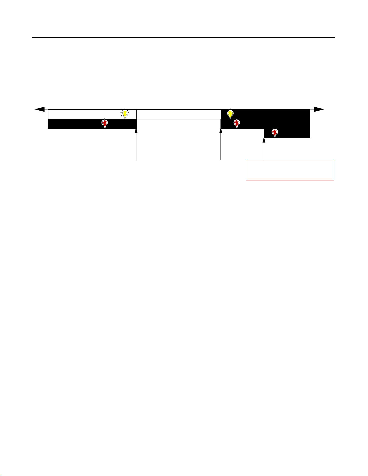
These alarm conditions are described in general terms and as they
relate to bits on the FLEX Ex I/O module on the following pages. The
graphic below shows at what values these alarms are generated for
Data Format 4.
Publication 1797-6.5.2 - February 2001
Page 12
1-4 About the FLEX Ex Thermocouple/RTD/mV Input Module
Data Format Alarm Example
In this example, the normal active data range is 4-20mA. The alarms
are generated in three overlapping bands.
PHYSICAL INPUT SIGNAL RANGE
CJC fault
underrange
overrange
CJC fault
Maximum
Measureable
Value
open w i re fault
Channel Data
Forced to
Maximum for Type
Minumum
Value for
Sensor
Type
normal signal range
Maximum
Value for
Sensor
Type
Overrange
If the input is greater than the maximum temperature of the
thermocouple or RTD range, millivolt (+100mV), or resistance (500W)
the overrange bit for that channel will be set.
Underrange
If the input is less than the minimum temperature of the thermocouple
or RTD range, millivolt (-40mV), or resistance (0W) the underrange bit
for that channel will be set.
Publication 1797-6.5.2 - Febr uary 2001
Open Wire
Individual channel fault alarm for broken wire. If a broken wire/
detached lead is detected, the data value is forced to maximum. In
RTD/W mode, input levels above 540W will set this bit; in
thermocouple/mV mode, input levels above 210mV will set this bit.
Cold Junction Compensation Alarm
Broken or detached lead or shorted lead detection is included for
CJCs. This detection is only available when the input type selected is
thermocouple and sensor mode is set to CJC compensation.
When either CJC fails its fault is reported. Both CJCs ae normally used
in compensation calculations. If one CJC fails, calculations use the
remaining good device. If both fail, calculations use the last good
value.
Page 13

About the FLEX Ex Thermocouple/RTD/mV Input Module 1-5
Data Formats and Fault Modes
The tables below shows the bit settings for the data formats and fault
modes for your FLEX Ex thermocouple/RTD/mV module.
Data Formats
Bit 11 10 09 08 Data type for channels 0 thru 7
0000
0001
0010
0 0 1 1 -32767 to +32767
0 1 0 0 0 to 65535
0101 thru 1111 not used
Note: Module defaults to -4000 to 10,000 in millivolt mode, and 0 to 5000 in ohms mode
o
C (see note)
o
F (see note)
o
K (see note)
Chapter Summary
Fault Mode
Bit 06 Fault enable for channels 0-3
07 Fault enable for channels 4-7
0 = disabled
1 = enable wire-off detection
In this chapter, we told you about the FLEX Ex system and the
thermocouple/RTD/mV module, and how it communicates with
programmable controllers.
Publication 1797-6.5.2 - February 2001
Page 14

1-6 About the FLEX Ex Thermocouple/RTD/mV Input Module
Publication 1797-6.5.2 - Febr uary 2001
Page 15

Understanding Configurable FLEX Ex
Thermocouple/RTD/mV Input
Module Features
Chapter
2
What this Chapter Contains
Read this chapter to familiarize yourself with configurable features on
the 1797-IRT8 module.
For information on: See page:
Setting a FLEX Ex Thermocouple/RTD
Module’s Operating Status
Input Type Select 2-2
Sensor Type Select 2-2
Data Format 2-4
Preset Temperature Select 2-5
RTD Loop Resistance Offset Select 2-6
Fault Mode Select 2-7
Using Module Alarms 2-7
Overrange Alarm 2-7
Underrange Alarm 2-8
Fault Alarm 2-9
Chapter Summary 2-9
This chapter describes the following features:
2-2
Input type
•
Sensor type
•
• Data formats
• Preset temperature selection
• RTD loop resistance offset selections
• F a ult mode
• Overrange Alarms
• Und errange alarms
• Fault alarms
Important:You must use your programming software to configure
these features. A brief description of each module feature
is provided in this chapter, but you must use the online
help included with your programming software to perform
specific configuration.
1 Publication 1797-6.5.2 - February 2001
Page 16

2-2 Understanding Configurable FLEX Ex Thermocou ple/RTD/mV Input Module Features
Setting a FLEX Ex
Thermocouple/RTD
Module’s Operating
Status
Input Type Select
Select the thermocouple or RTD mode for input channel groups 0-3
and 4-7. If 2 is selected, the module defaults to thermocouple. If 3 is
selected, the module defaults to RTD.
Range: 0 = thermocouple, 1 = RTD, 2 and 3 not used
Bits 06-07 Input Type Select
Bit 07 06 Input type sel ect ion for channels 0-3
0 0 Thermocouple
01RTD
10
11
Input type select for channels 4 through 7 use bits in word 1.
Not used
Sensor Type Select
Select the type of sensor for input channel groups 0-3 and 4-7.
Thermocouple mode 0 = mV, 1 = B, 2 = E, 3 = J, 4 = K, 5 = TXK/
XK(L), 6 = N, 7 = R, 8 = S, 9 = T, 10-15 not used.
RTD mode: 0 = W , 1 = Pt100 IEC 751 Amen dment 2, 2 = Pt200 IEC 751
Amendment 2, 3 = Pt1 00 JIS C1604-1989, 4 = Pt200 JIS C1604- 1989, 5 =
Ni100 DIN 43760-1987, 6 = Ni200 DIN 4376 0-1987, 7 = Ni120 Min co, 8
= Cu10 Minco, 9-15 not used.
If unused settings are chosen, diagnostic status “2 = configuration
failure” will be set, and the last valid configuration will be used. The
default = 0.
Publication 1797-6.5.2 - Febr uary 2001
Page 17

Understanding Configurable FLEX Ex Thermocouple/RTD/mV Input Module Features 2-3
Bits 00-03 Sensor Type (Thermocouple or RTD)
RTD Type
Bit03020100Sensor type for channels 0 through 3
0000Resistance (default)
0001100 ohm Pt α = 0.00385 Euro (–200 to +870°C)
0010200 ohm Pt α = 0.00385 Euro (–200 to +400°C)
0011100 ohm Pt α = 0.003916 U.S. (–200 to +630°C)
0100200 ohm Pt α = 0.003916 U.S. (–200 to +400°C)
0101100 ohm Nickel (–60 to +250°C)
0110200 ohm Nickel (–60 to +200°C)
0111120 ohm Nickel (–80 to +320°C)
100010 ohm Copper (–200 to +260°C)
1001 through 1111 not used
Bits 00-03 Thermocouple Type
Bit03020100Sensor type for channels 0 through 3
0000mV (default)
0001B 300 to 1800°C (572 to 3272°F)
0010E –250 to 1000°C (–418 to 1832°F)
0011J –210 to 1200°C (–346 to 2192°F)
0100K –250 to 1372°C (–418 to 2502°F)
0101L –200 to 800°C (–328 to 1472°F)
0110N –250 to 1300°C (–418 to 2372°F)
0111R –0 to 1768°C (32 to 3214°F)
1000S –0 to 1768°C (32 to 3214°F)
1001T –250 to 400°C (–418 to 752°F)
1010 through 1111 not used
Input Filter Cutoff
A series of eight available input filters – filters are hardware and
software – allow you to choose the best rolloff frequency for input
channels on your I/O module. When choosing a filter, remember that
time frequency rolloff may affect your input signal’s accuracy.
For example, in configuration word 0, if you choose the fastest time
frequency of 600Hz (hardware filter only), little noise is added, but the
slowest frequency of 0.2Hz will provide the most accurate process
noise filtering. See below to decide which input filter to use in your
application:
Publication 1797-6.5.2 - February 2001
Page 18

2-4 Understanding Configurable FLEX Ex Thermocou ple/RTD/mV Input Module Features
Input Filter Cutoff bits
Bit020100Definition
0 0 0 Hardware filtering only (default filtering) 600Hz (1.7ms)
0 0 1 40Hz (25ms)
0 1 0 10Hz (100ms)
0 1 1 4Hz (250ms)
1 0 0 2Hz (500ms)
1011Hz(1s)
1100.5Hz(2s)
1110.2Hz(5s)
Choose the best input filter cutoff in your programming software.
Data Format
You must choose a module data format in your user program. Select
the format by setting bits as shown below. Note that this parameter
affects channel accuracy.
Data format – module defaults to –4000 to 10000 in millivolt mode, and 0 to 5000 in ohms mode
Bit 11 10 09 08 Data type for channels 0-7
0000°C
0001°F
0010×K
0 0 1 1 –32767 to +32767
0 1 0 0 0 to 65535
0101 through 1111 not used
o
C, oF and oK will have formats appropriate to the selected
thermocouple or RTD range (e.g. -xxxx to +xxxx with 1 decimal place
implied - 3500 = 350.0). For Cu10 RTD, 2 decimal points are implied.
If using mV, data format defaults to -4000 to +10000 (2 decimal points
implied (e.g. -40 to 100.00). If using W mode selection, data format
defaults to 0 to 5000 (1 decimal point implied, e.g. 0.- to 500.0).
In the thermocouple and RTD modes, if unused data formats are
o
chosen, the module will default to
C.
Publication 1797-6.5.2 - Febr uary 2001
Page 19

Understanding Configurable FLEX Ex Thermocouple/RTD/mV Input Module Features 2-5
Sensor Mode Select
Selects the sensor mode for input channels 0-3 and 4-7.
If using cold junction compensation, both CJCs must be installed. The
difference between the CJCs will be linearly apportioned to each
thermocouple channel based on its position across the base. If one
CJC is broken or missing, the remaining CJC is used t o compensate all
channels. The appropriate CJC alarm will be set in this case. If the
second CJC fails, the last valid reading is frozen for compensation use.
The second CJC alarm will also be set.
When using only channels 0-3 for thermocouples, connect the CJCs to
terminals 5 and 12. If only using channels 4-7, connect the CJCs to
terminals 22 and 29. If all channels are configured for thermocouples,
connect the CJCs to terminals 5 and 29.
When CJC thermistor temperature compensation is sele cted for one
channel group, all channels configured for thermocouple inputs will
use the CJC compensation.
05 04 Sensor mode for channels 0 thru 3
Bit
13 12 Sensor mode for channels 4 thru 7
Thermocoupl e Mode
00
0 1 Internal compensation - Uses the value selected for reference junction
10
1 1 Differential measurement between 2 channels
0 0 2-wire RTD - no compensation
0 1 2-wire RTD with user compensation
1 0 3-wire RTD
1 1 4-wire RTD
External compensation - uses cold junction sensors
o
No compensation (Data is referenced to 0
RTD Mode
C)
Preset Temperature Select
This parameter is used if Input Type Select is set to thermocouple and
Sensor Mode Select is set to fixed compensation. This parameter then
sets a fixed reference temperature used to compensate all
thermocouple channels.
The default = 0.
Publication 1797-6.5.2 - February 2001
Page 20

2-6 Understanding Configurable FLEX Ex Thermocou ple/RTD/mV Input Module Features
Bits 03-05 Reference Junction – used when input type is set to thermocouple and sensor
mode is set to fixed compensation. Sets a fixed reference junction to compensate
all thermocouple channels.
Bit050403Reference Junction
0000°C
00120°C
01025°C
01130°C
10040°C
10150°C
11060°C
11170°C
RTD Loop Resistance Offset Select
This parameter is used if Input Type Select is set to RTD and Sensor
Mode Select is set to 2-wire with loop resistance compensation. This
parameter then sets total RTD loop resistance compensation for each
RTD channel. Either the value stored for each channel during
calibration is used to compensate the module RTD channels, or one of
3 fixed values is used to compensate module RTD channels.
This parameter is disabled for Cu10 RTDs.
00-15 (00-17) RTD loop resistance offset select bits – used input type is set to RTD and sensor
mode select is set to 2-wire with loop resistance compensation. Allows you to set
the type of RTD loop resistance compensation used for all RTDs or one of three fixed
values for all channels. NOTE: Not applicable to 10W copper RTD, which defaults to
0W.
Bit 01 00 RTD channel 0
Bit 03 02 RTD channel 1
Bit 05 04 RTD channel 2
Bit 07 06 RTD channel 3
Bit 09 08 RTD channel 4
Bit 11 10 RTD channel 5
Bit 13 12 RTD channel 6
Bit 15 14 RTD channel 7
0 0 Use channel loop compensation value stored during
calibration procedure for 2-wire RTD (default = 0W)
015W
1 0 10W
1 1 15W
Range: 0 = use channel loop compensation value determined and
stored during calibration procedure for 2-wire RTD, 1 = 5Ω, 2 = 10Ω,
3= 15Ω. Default = 0.
Publication 1797-6.5.2 - Febr uary 2001
Page 21

Understanding Configurable FLEX Ex Thermocouple/RTD/mV Input Module Features 2-7
Fault Mode Select
Select whether the channel fault detection is enabled or disabled for
channels 0-3 and 4-7.
Range: 0 = disable, 1 = fault detection enabled (wire off, mV
overvoltage, RTD open). Default = 0.
Using Module Alarms
Bits 06-07 Fault Mode bits – when a bit is set (1), fault mode is enabled for that channel.
Bit 06 corresponds to channels 0-3; bi t 07 corresponds to channels 4-7.
0 = disabled
1 = enable wire-off detection
FLEX Ex I/O modules are capable of generating four alarms:
Overrange
•
Underrange
•
Fault
•
Cold Junction Compensation (CJC) Fault
•
These alarm conditions are described in general terms and as they
relate to bits on the FL EX Ex I/O module on the following pages.
Overrange Alarm
The channel overrange alarm is set if the input is greater than the
maximum temperature (thermocouple or RTD range dependent),
millivolt (+100mV) or resistance (500Ω) range value.
Range: 0 = normal, 1 = input overrange. Default = 0.
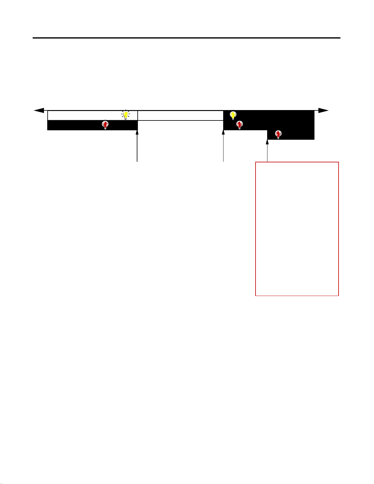
This alarm stays active at any value above 100% of range and is
always enabled by the module. Refer to the figure below for the
sensor dependent signal which causes this alarm to be generated.
Publication 1797-6.5.2 - February 2001
Page 22
2-8 Understanding Configurable FLEX Ex Thermocou ple/RTD/mV Input Module Features
IRT8 Specific alarming performance
PHYSICA L I NPUT SIGNAL RANGE
underran ge
CJC fault
Sensor Type
IEC PT100
IEC PT200
JIS PT100
JIS PT200
DIN Ni100
DIN Ni200
Minco Ni120
Minco Cu10
0-500 Resistance
millivolt ~ 210mV
B
E
J
K
N
R
S
T
Cold Junction Compensation
normal signal range
-200C + 870C
-200C +400C
-200C +630C
-200C +400C
-60C +250C
-60C +200C
-80C +320C
-200C +260C
0ohm 500ohm
-40mV +100mV
300C +1800C
-250C +1000C
-210C +1200C
-250C
-200C + 800CTXK/XK(L)
-250C +1300C
0C
0C
-250C + 400C
-20C 100C
+1372C
+1768C
+1768C
overrange
CJC faul t
open w i re f ault
~ 520ohm equivalent
~ 520ohm equivalent
~ 520ohm equivalent
~ 520ohm equivalent
~ 520ohm equivalent
~ 520ohm equivalent
~ 520ohm equivalent
~ 520ohm equivalent
~ 520ohm
~ 210mV equivalent
~ 210mV equivalent
~ 210mV equivalent
~ 210mV equivalent
~ 210mV equivalent
~ 210mV equivalent
~ 210mV equivalent
~ 210mV equivalent
~ 210mV equivalent
Channel
Data
Forced
to
Maximum
for Type
Publication 1797-6.5.2 - Febr uary 2001
Underrange A l arm
The channel underrange alarm is set if the input is less than the
minimum temperature (thermocouple or RTD range dependent),
millivolt (-40mV) or resistance (0Ω) range value.
Range: 0 = normal, 1 = input overrange. Default = 0.
This alarm stays active at any value below 0% of range and is always
enabled by the module.
Range: 0 = normal, 1 = input overrange. Default = 0.
Page 23

Understanding Configurable FLEX Ex Thermocouple/RTD/mV Input Module Features 2-9
Fault Alarm
The module has individual channel fault alarms for a broken or
detached wire. In any mode, if a broken/detached lead is detected,
the data value is forced to maximum. Once the alarm is issued, it
remains active as long as the input signal is faulted.
In mV mode, for input levels above 210mV, this bit is set.
In RTD mode, an open input will set this bit.
Range: 0 = normal,1 = wire off, excessive input fault detected.
Default = 0.
Chapter Summary
In this chapter , we told you about the F LEX Ex sys tem and the analog
I/O modules, and how they communicate with programmable
controllers.
Publication 1797-6.5.2 - February 2001
Page 24

2-10 Understanding Configurable FLEX Ex Thermocouple/RTD/mV Input Module Features
Publication 1797-6.5.2 - Febr uary 2001
Page 25
Chapter
How to Install Your FLEX Ex Thermocouple/ RTD/mV Module
3
What this Chapter Contains
Before You Install Your Analog Module
Read this chapter to install the 1797-IRT8 thermocouple/RTD/mV
module.
For information on: See page:
Before You Install Your Analog
Module
Compliance to European Union
Directives
Installation in Zone 1 3-2
Removal and Insertion Under Power 3-3
Installing the Module 3-3
Connecting Wiring to the FLEX Ex
Thermocouple/RTD/mV Module
Grounding the Module 3-13
Chapter Summary 3-13
Before installing your FLEX Ex analog module:
You need to: As described under:
Verify that the module will be installed in a
suitable metal enclosure
3-1
3-2
3-10
Installation in Zone 1, page 3-2
Position the keyswitch on the
terminal base
ATTENTION
These modules do not receive primary operational
power from the backplane. +/-V dc power must be
applied to your module before installation. If power
is not applied, the module position will appear to the
adapter as an empty slot in your chassis.
Installing the Module, page 3-8
!
1 Publication 1797-6.5.2 - February 2001
Page 26

3-2 How to Install Your FLEX Ex Thermocouple/RTD/mV Module
Compliance to European Union Directives
If this product has the CE mark, it is approved for installation within
the European and EEA regions. It has been designed and tested to
meet the following directives.
EMC Directive
This product is tested to meet the Council Directive 89/336/EC
Electromagnetic Compatibility (EMC) by applying the following
standards, in whole or in part, documented in a technical construction
file:
EN 50081-2 EMC - Generic Emission Standard, Part 2 - Industrial
•
Environment
EN 50082-2 EMC - Generic Immunity Standard, Part 2 - Industrial
•
Environment
This product is intended for use in an industrial environment.
Ex Directive
Installation in Zone 1
This product is tested to meet the Council Directive 94/9/EC (ATEX
100a) Equipment and Protective Systems Intended for Use in
Potentially Explosive Atmospheres by applying the following
standards:
EN50014:1992, Electrical Apparatus for Potentially Explosive
•
Atmospheres
EN50020:1994, Electrical Apparatus for Potentially Explosive
•
Atmospheres - Intrinsic Safety “i”
prEN50284:1997, Special requirements for construction, test and
•
marking of electrical apparatus of equipment group II, category
1G
This module must not be exposed to the environment. Provide a
suitable metal enclosure.
ATTENTION
This module cannot be used in an
intrinsically safe environment after it has
been exposed to non-intrinsically safe
signals.
Publication 1797-6.5.2 - Febr uary 2001
!
Page 27

How to Install Your FLEX Ex Thermocouple/RTD/mV Module 3-3
Electrostatic Charge
Removal and Insertion Under Power
Installing the Module
Protect the system against electrostatic charge. Post a sign near this
module: Attention! Avoid electrostatic charge. For your
convenience, a sign which can be cut out and posted is included in
this user manual before the back cover.
ATTENTION
!
Installation of this module consists of:
mounting the terminal base unit
•
installing the analog I/O module into the terminal base unit
•
installing the connecting wiring to the terminal base unit
•
This module is designed so you can remove and
insert it under power. However, take special care
when removing or inserting this module in an
active process. I/O attached to any module being
removed or inserted can change states due to its
input/output signal changing conditions.
If you are installing your module into a terminal base unit that is
already installed, proceed to “Mounting the 1797-IRT8 Module on the
Terminal Base” on page 8.
ATTENTION
!
Moun ting on a DIN Rail
ATTENTION
Make certain that you power this terminal base module
combination with an instrinsically safe power supply.
Do not exceed the values listed in the specifications for
the terminal base or module.
Do not use the unused terminals on the terminal
base unit. Using the terminals as supporting
terminals can result in damage to modules and/or
unintended operation of your system.
Do not remove or replace a terminal base unit when
power is applied. Interruption of the flexbus can
result in unintended operation or machine motion.
!
Publication 1797-6.5.2 - February 2001
Page 28

3-4 How to Install Your FLEX Ex Thermocouple/RTD/mV Module
1. Remove the cover plug in the male connector of the unit to
which you are connecting this terminal base unit.
2. Check to make sure that the 16 pins in the male connector on
the adjacent device are straight and in line so that the mating
female connector on this terminal base unit will mate correctly.
3. Make certain that the female flexbus connector is fully
retracted into the base unit.
4. Position the terminal base over the 35 x 7.5mm DIN rail A
(A-B pt. no. 199-DR1).
A
A
Position terminal base at a slight angle and
hooked over the top of the DIN rail A.
Slide the terminal base over tight against the adapter (or proceeding terminal
base). Make sure the hook on the terminal base slides under the edge of the
adapter (or proceeding terminal base) and the flexbus connector is fully retracted.
ATTENTION
Do not force the terminal base into the adjacent
modules. Forcing the units together can bend or
break the hook and allow the units to separate
and break communication over the backplane.
41106
41107
Publication 1797-6.5.2 - Febr uary 2001
!
Page 29

How to Install Your FLEX Ex Thermocouple/RTD/mV Module 3-5
5. Rotate the terminal base onto the DIN rail with the top of the rail
hooked under the lip on the rear of the terminal base. Use
caution to make sure that the female flexbus connector
does not strike any of the pins in the mating m a le
connector.
41108
Press down on the terminal base unit to lock the terminal base on the DIN rail. If
the terminal base does not lock into place, use a screwdriver or similar device t o
open the locking tab, press down on the terminal base until flush with the DIN rail
and release the locking tab to lock the base i n pl ace.
Gently push the flexbus connector into the side of the adapte r (or pr oceeding
terminal base) to complete the backplane connection.
41109
6. For specific wiring information, refer to the installation
instructions for the module you are installing in this terminal
base unit. Terminal assignments are also given later in this
chapter, see page 3-10.
7. Repeat the above steps to install the next terminal base.
8. Install the flexbus connector cover on the last terminal base is in
place.
Publication 1797-6.5.2 - February 2001
Page 30

3-6 How to Install Your FLEX Ex Thermocouple/RTD/mV Module
Panel/Wall Mounting
Installation on a wall or panel consists of:
laying out the drilling points on the wall or panel
•
drilling the pilot holes for the mounting screws
•
mounting the adapter mounting plate
•
installing the terminal base un its and securing them to the wall
•
or panel
If you are installing your module into a terminal base unit that is
already installed, proceed to Mounting the 1797-IRT8 Module on the
Terminal Base Unit on page 3-8.
Use the mounting kit Cat. No. 1794-NM1 for panel/wall mounting.
1 - Mounting Plate for Adapter
2 - 18 #6 self -tapping screws
(2 for the adapter, and 2
each for up to 8 modules)
Adapter Module
(not included)
1.4
(35.5)
1
2
41547
Terminal Base Unit
(not included)
To install the mounting plate on a wall or panel:
Publication 1797-6.5.2 - Febr uary 2001
Page 31

How to Install Your FLEX Ex Thermocouple/RTD/mV Module 3-7
1. Lay out the required points on the wall/panel as shown in the
drilling dimension drawing.
Drilling Dimensions for Panel/Wall Mounting of FLEX Ex I/O
.83 (21)
2.0
(50)
Inches
(Millimeters)
!
1.4
(35.5)
2.3
(58.5)
1.4
(35.5)
ATTENTION: Be careful of metal chips when
drilling cable mounting hol es. Do not drill holes
above a system that has any modules installed.
2. Drill the necessary holes for the #6 self-tapping mounting
screws.
2.3
(58.5)
Cable length
approximately 11.5
(292.1) or 35.5
(901.0) from upper
connector [length
depends upon
cable -1ft (0.3m) or
3ft (0.091m)]
1.4
(35.5)
1.6
(40.5)
(15.6)
+V
1
.61
-V
2
.3
(8)
+V
-V
3
4
40871
3. Mount the mounting plate (1 ) fo r the ad apter modu le us ing two
#6 self-tapping screws (18 included for mounting up to 8
modules and the adapter).
Make certain that the mounting plate is properly grounded to the
panel. Refer to “Industrial Automation Wiring and Grounding
Guidelines,” publication 1770-4.1.
4. Hold the adapter (2) at a slight angle and engage the top of the
mounting plate in the indention on the rear of the adapter
module.
5. Press the adapter down flush with the panel until the lockin g
lever locks.
6. Position the terminal base unit up against the adapt er and push
the female bus connector into the adapter.
7. Secure to the wall with two #6 self-tapping screws.
8. Repeat for each remaining terminal base unit.
Publication 1797-6.5.2 - February 2001
Page 32

3-8 How to Install Your FLEX Ex Thermocouple/RTD/mV Module
Mounting the 1797-IRT8 Module on the Terminal Base Unit
The 1797-IRT8 module mounts on a 1797-TB3 or TB3S intrinsically
safe terminal base unit.
1. Rotate keyswitch (1) on terminal base unit (2) clockwise to
position 2 as required for this type of module. Do not change
the position of the keyswitch after wiring the terminal
base unit.
7
4
Label under here
or under here
3
5
1
8
2
6
40231
2. Make certain the flexbus connector (3) is pushed all the way to
the left to connect with the neighboring ter minal ba se/ adapte r.
You cannot install the module unless the connector is fully
extended.
Publication 1797-6.5.2 - Febr uary 2001
3. Make sure the pins on the bottom of the module are straight so
they will align properly with the connector in the terminal base
unit.
4. Position the module (4) with its alignment bar (5) aligned with
the groove (6) on the termin a l base .
5. Press firmly and evenly to seat the mo dule in the terminal base
unit. The module is seated when the latching mechanism (7) is
locked into the module.
Page 33

How to Install Your FLEX Ex Thermocouple/RTD/mV Module 3-9
6. Make certain that you only connect terminal base units to other
intrinsically safe system modules or adapters to maintain the
integrity of the intrinsically-safe backplane.
7. Remove cap plug (8) and attach another intrinsically safe
terminal base unit to the right of this terminal base unit if
required. Make sure the last terminal base has the cap plug (8)
in place.
41307
The adapter is capable of addressing eight modules. Do not exceed
a maximum of eight terminal base units in your system.
Wiring the Terminal Base Units
Wiring the FLEX Ex I/O modules is done through the 1797-TB3 and
1797-TB3S terminal base units.
ATTENTION
!
The FLEX Ex I/O modules do not receive primary
operational power from the backplane. +/- V dc
power must be applied to your module before
operation. If power is not applied, the module
position will appear to the adapter as an empty
slot in your chassis. If the adapter does not
recognize your module after installation is
completed, cycle power to the adapter.
Make certain that you power these modules w ith an
intrinsically safe power supply. Do not exceed the
values listed in the specifications for the modules.
Publication 1797-6.5.2 - February 2001
Page 34

3-10 How to Install Your FLEX Ex Thermocouple/RTD/mV Module
Connecting Wiring to the FLEX Ex Thermocouple/ RTD/mV Module
Inputs/Outputs
Each input can be operated from a thermocouple (TC), resistance
temperature detector (RTD), or millivolt. Do not apply any
non-intrinsically safe signals to this module.
When using an intrinsically safe electrical apparatus according to
EN50020, the European directives and regulations must be follow ed.
The channels in this module are electrically connected to each other
and have a common plus-line.
When interconnecting several lines, you must consider the total
accumulated power and check for intrinsic safety.
Connections for the 1797-IRT8 Module
+V
Power
Supply
-V
FLEX Bus
Bus
+
H
Thermocouple
uC
L
-
+
CJC
-
CJC
2W RTD
+
mV
-
3W RTD
4W RTD
Row A
Row B
Row C
0 1 2 3 4 5 6 7 8 9 10 11 12 13 14 15
Ch 1
H
-
+
L
-
+
L
Ch 2
Ch 6
-
LH
+
-
LH
Ch 3
-
LH
+
-
LH
Ch 7
CJC
1+
1-
Chassis
GND
for shield
+
LH
H
+
-
Ch 0
16 17 18 19 20 21 22 23 24 25 26 27 28 29 30 31 32 33
+
-
+
LH
Ch 4 Ch 5
34 35 36 37 38 39 40 41 42 43 44 45 46 47 48 49 50 51
+V -V +V -V
0+
CJC
Chassis
GND
for shield
0-
No connection allowed to terminals 36 and 49
41505
Publication 1797-6.5.2 - Febr uary 2001
Page 35

How to Install Your FLEX Ex Thermocouple/RTD/mV Module 3-11
Wiring connections for the 1797-IRT8 Module
1. For RTD inputs:
a. connect the individual source current input wiring to (+)
terminals for each individual channel (0, 4, 8 and 12) on the 0-15
row (A) and terminals 17, 21, 25, and 29 on the 16-33 row (B) as
indicated in the table below.
b. connect the associated signal return (-) to the corresponding (- )
terminals (3, 7, 11, and 15) on the 0-15 row (A), and terminals 20,
24, 28 and 32 on the 16-33 row (B).
2. For thermocouple inputs:
a. connect the individual high signal input wiring to (L) terminals
for each individual channel (2, 6, 10, and 14) on the 0-15 row (A)
and terminals 19, 23, 27 and 31 on the 16-33 row (B) as indicated
in the table below.
b. connect the associated low signal (-) to the corresponding (-)
terminals (3, 7, 11 and 15) on the 0-15 row (A), and terminals 20,
24, 28, and 32 on the 16-33 row (B).
c. connect cold junction compensation wiring to terminals 37, 38
and 39, and terminals 46, 47 and 48.
d. Connect the tail of the CJC as follows:
• when using inputs 0-3 (row A) only for thermocouple inputs:
connect the tail of CJC1 to terminal 5 and CJC2 to terminal 12 on
row A.
• when using inputs 4-7 (row B) only for thermocouple inputs:
connect the tail of CJC1 to terminal 22 and CJC2 to term inal 29
on row B.
• when using thermocouple inputs 0-7: connect the tail of CJC1 to
terminal 5 on row A, and CJC2 to terminal 29 on row B.
Importan t : Whenever you use thermocouple inputs, you must use
both cold junction compensators.
3. Connect +V to terminal 34 on the 34-51 row (C).
4. Connect -V to terminal 35 on the 34-51 row (C).
ATTENTION
ATTENTION:Make certain that you power this
module with an int rinsically safe power supply . Do
not exceed the values listed in the specifications
for this module.
!
5. If continuing power to the next terminal base unit, connect a
jumper from terminal 50 (+V) on this base unit to terminal 34 on
the next base unit.
6. If continuing common to the next terminal base unit, connect a
jumper from terminal 51 (-V) on this base unit to termin al 35 on
the next base unit.
Publication 1797-6.5.2 - February 2001
Page 36

3-12 How to Install Your FLEX Ex Thermocouple/RTD/mV Module
1
2
3
1a
2a
1
2
1
2
1
2
1
2
2-wire RTD
3-wire RTD
4-wire RTD
Thermocouple
Millivolt
Type of Input
Connect the following:
+HL-
RTD - 2-wire 1 2
RTD - 3-wire 1 3 2
RTD - 4-wire 1 1a 2a 2
Thermocouple 1 2
Millivolt 1 2
1Terminals 16, 33, 40 thru 45 are chassis ground.
RTD or
Thermocouple
Channel
00123
RTD Source
Current
(+)
High Signal
Terminal (H)
Low Signal
Terminal (L)
14567
2891011
312131415
417181920
521222324
625262728
729303132
+V Terminals 34 and 50
-V Terminals 35 and 51
1 Terminals 37, 38 and 39 and 46, 47 and 48 are for cold junction
compensation (with 38 and 47 chassis ground). Connect CJC1 to
terminal 5 or 21, CJC2 to terminal 12 or 29
2 Terminals 16, 33, and 40 thru 45 are chassis ground.
Shield
Signal
Return
(-)
1
Publication 1797-6.5.2 - Febr uary 2001
Page 37

How to Install Your FLEX Ex Thermocouple/RTD/mV Module 3-13
Grounding the Module
All I/O wiring must use shielded wire. Shields must be terminated
external to the module, such as bus bars and shield-terminating feed
throughs.
30820-M
Chapter Summary
In this chapter, we told you how to install your thermocouple/RTD/
mV module in an existing programmable controller system and how
to wire to the terminal base units.
Move to chapter 3 to learn about input, output and configuration files
for the thermocouple/RTD/mV module on ControlNet.
Publication 1797-6.5.2 - February 2001
Page 38

3-14 How to Install Your FLEX Ex Thermocouple/RTD/mV Module
Publication 1797-6.5.2 - Febr uary 2001
Page 39

Chapter
4
Input, Status, Output and Configuration Files
for the Thermocouple/RTD/mV Module on
the ControlNet Network
What this Chapter Contains
Read this chapter to familiarize yourself with input, output and
configuration files for the thermocouple/RTD/mV module on
ControlNet.
For information on: See p age:
Using Programming Software in Y ou r
FLEX Ex Application
Using Programming Software in Y ou r
FLEX Ex Application
Communication Over the FLEX Ex
Backplane
I/O Structure 4-4
Fault State Data 4-6
Device Actions 4-6
Chapter Summary 4-14
In this chapter, you will learn about:
using software to configure the FLEX Ex I/O modules
•
ControlNet Ex Adapter
•
I/O structure
•
• fault state data
• communication fault data
• idle state behavior
• input data behavior upon module removal
This chapter provides a brief description of the steps you must
take in your programming software to configure FLEX Ex I/O
modules and an overview of what occurs during configur ation .
4-2
4-2
4-2
For a full explanation of how to use your programming
software to perform module configuration, use the
software online help.
Publication 1797-6.5.2 - February 2001
Page 40

4-2 Input, Status, Output and Configuration Files for the Thermocouple /R TD/mV Module on the ControlNet Net w or k
Using Programming Software in Your FLEX Ex Application
When using FLEX Ex thermocouple/RTD/mV modules, you must
perform I/O mapping and configure the ControlNet network before
generating configuration data for your I/O modules.
For example, you may use RSNetWorx™ to connect FLEX Ex I/O
modules to a ControlNet processor or scanner through a FLEX Ex
ControlNet Ex adapter (cat. no. 1797-ACNR15). The I/O configuration
portion of another programming software, for example RSLogix5™
could be used to generate the configuration data for each I/O module
in the control system.
Configuration data is then transferred to the controller during the
program download and subsequently transferred to the appropriate I/
O modules.
Follow these general guidelines when configuring I/O modules:
1. Perform I/O mapping.
2. Instruct the FLEX Ex I/O modules to use I/O mapping file from
step 1.
3. Configure all I/O modules.
About the ControlNet Ex Adapter
Communication Over the FLEX Ex Backplane
Networ
ControlNet Ex
Adapter
Write
The FLEX Ex ControlNet Ex ada pter (cat. no. 1 797-ACNR15) i nterfaces
up to 8 FLEX Ex modules to a ControlNet processor or scanner. The
adapter can support ControlNet real-time data connec tion s to
individual modules or module groups. Each connection is
independent of the others and can be from different processors or
scanners.
One 1797-ACNR15 ControlNet Ex adapter can interface up to eight
terminal base units with installed FLEX Ex modules, forming a FLEX
Ex system of up to eight slots. The adapter communicates to other
network system components (typically one or more controlle rs or
scanners, and/or programming terminals) over the ControlNet
network. The adapter communicates with its I/O modules over the
FLEX Ex back plane.
Read
I/O Module I/O ModuleI/O Module
Inputs Inputs Inputs
Status
Outputs
Configuration Configuration Configuration
Slot 0 Slot 1 Slot 7
0
Read
Words
Write
Words
X
StatusStatus
OutputsOutputs
41626
Publication 1797-6.5.2 - Febr uary 2001
Page 41

Input, Status, Output and Confi gur at ion Files for the Thermocouple/RTD / mV Module on the ControlNet Network 4-3
Scheduled Data-T ransfer
Scheduled data transfer:
is continuous.
•
is asynchronous to the controller program scan.
•
occurs at the actual rate displayed in the Actual Packet Interval
•
field on the programming software ControlNet I/O mapping
(monitor) screen
Unscheduled Data-Transfer
Unscheduled operations include:
unscheduled non-discrete I/ O data transfers–throu gh ControlNet
•
I/O Transfer (CIO) instructions
peer-to-peer messaging–through message (MSG) instructions
•
messaging from programming devices
•
Unscheduled messaging on a ControlNet network is
non-deterministic. Your application and your configuration–number of
nodes, application program, NUT, amount of scheduled bandwidth
used, etc.–determine how much time there is for unscheduled
messaging.
Module I/O Mapping
The I/O map for a module is divided into read words and write
words. Read words consist of input and status words, and write
words consist of output and configuration words. The number of
read words or write words can be 0 or more. The length of each I/O
module’s read words and write words vary in size depending on
module complexity. Each I/O module will support at least 1 input
word or 1 output word. Status and configuration are optional,
depending on the module.
Publication 1797-6.5.2 - February 2001
Page 42

4-4 Input, Status, Output and Configuration Files for the Thermocouple /R TD/mV Module on the ControlNet Net w or k
For example, a 16 point discrete input module will have up to 2 read
words and 1 write word.
ControlNet Image
Input Size
1 Word
Status Size
1 Word
Configuration
Module Image
Input
Faults
I/O Structure
Network READ
1 Word
Check the I/O map for the module for the exact mapping.
Output data is received by the adapter in the order of the installed I/O
modules. The output data for slot 0 is received first, followed by the
output data for slot 1, and so on up to slot 7.
The first word of input data sent by the adapter is the Adapter status
word. This is followed by the input data from each slot, in the order
of the installed I/O modules. The input data from slot 0 is first after
the status word, followed by input data from slot 1, and so on up to
slot 7.
ControlNet Adapter
Read Data
Adapter Status
Slot 0 Input Data
Slot 1 Input Data
Not used
Delay
Time
Delay
Time
41627
Network WRITE
Publication 1797-6.5.2 - Febr uary 2001
Slot 7 Input Data
Slot 0 Output Data
Slot 1 Output Data
Slot 7 Input Data
Read
Write
I/O
Module
Slot 0
I/O
Module
Slot 1
I/O
Module
Slot 7
41628
Page 43

Input, Status, Output and Confi gur at ion Files for the Thermocouple/RTD / mV Module on the ControlNet Network 4-5
Adapter Status Word
The status word consists of:
I/O module fault bits – 1 status bit for each slot
•
Additionally, in the case of a PLC-5 controller, it adds:
node address changed – 1 bit (created by PLC-5 controller)
•
I/O status – 1 bit (created by PLC-5 controller)
•
Resulting in the following FLEX Ex adapter status word for a
PLC-5 controller.
I/O Module Fault Bits
Bit: 15 910 through 15 8 7 6 5 4 3 2 1 0
Table 4.A
Created by PLC-5 controller
Bit Description: Bit: Explanation:
I/O Module Fault
Node Address Changed
(Created by PLC-5
controller.)
I/O Status Bit
Node Address Changed Bit
41629
As an example, in a PLC-5 system, the adapter status word bit
descriptions are shown in the following table.
0 This bit is set (1) when an error is detected in slot position 0.
1 This bit is set (1) when an error is detected in slot position 1.
2 This bit is set (1) when an error is detected in slot position 2.
3 This bit is set (1) when an error is detected in slot position 3.
4 This bit is set (1) when an error is detected in slot position 4.
5 This bit is set (1) when an error is detected in slot position 5.
6 This bit is set (1) when an error is detected in slot position 6.
7 This bit is set (1) when an error is detected in slot position 7.
8 This bit is set (1) when the node address switch setting has
been changed since power-up.
I/O State (Created by
PLC-5 controller.)
9 Bit = 0 -idle
bit = 1 - run
10 though 15 Not used – set to 0
Publication 1797-6.5.2 - February 2001
Page 44

4-6 Input, Status, Output and Configuration Files for the Thermocouple /R TD/mV Module on the ControlNet Net w or k
Possible causes for an I/O Module Fault are:
transmission errors on the FLEX Ex backplane
•
a failed module
•
a module removed from its terminal base
•
incorrect module inserted in a slot position
•
the slot is empty
•
the slot contains a non-discrete module
•
Fault State Data
Device Actions
The ControlNet Ex adapter provides storage for alternate module
output data during communication faults or processor idle state. This
“fault state data” assures that a known output will be applied to the
output devices during the previously mentioned modes. The
processor or scanner software must include the means to specify this
fault state data for each module. If applicable, this data is sent in the
configuration block, see Image Table Mapping on pages 4-8.
Device actions include:
communication fault behavior
•
idle state behavior
•
input data behavior upon module removal
•
Communication Fault Behavior
You can configure the adapter response to a communication fault for
each I/O module in its system. Upon detection of a communication
fault,
the adapter ca n:
Publication 1797-6.5.2 - Febr uary 2001
• leave the module output data in its last state (hold last state)
• reset the module output data to zero (reset)
• apply fault state data to the modu le output
Page 45

Input, Status, Output and Confi gur at ion Files for the Thermocouple/RTD / mV Module on the ControlNet Network 4-7
Idle State Behavior
The ControlNet Ex adapter can detect the state of the controlling
processor or scanner. Only 2 states can be detected:
– run mode,
– or program mode (idle).
When run mode is detected, the adapter copies the output data
received from the processor to the corresponding module output.
When program mode is detected, the adapter can be configured to:
leave the module output data in its last state (hold last state)
•
reset the module output data to zero (reset)
•
apply fault state data to the module output
•
Input Data Behavior upon Module Removal
I/O module input data sent by the adapter upon module removal is
configurable. The adapter can:
reset the module input data sent by the adapter to zero (reset)
•
leave the module input data sent by the adapter in the last state
•
before module removal (hold last state)
Publication 1797-6.5.2 - February 2001
Page 46

4-8 Input, Status, Output and Configuration Files for the Thermocouple /R TD/mV Module on the ControlNet Net w or k
Thermocouple/RTD/mV Input Module (1797-IRT8) Image Table
Mapping
Module Image
Input Data Channel 0
I/O Image
Input Size
1 to 11 Words
Overrange
Output Size
Input Data Channel 1
Input Data Channel 2
Input Data Channel 3
Input Data Channel 4
Input Data Channel 5
Input Data Channel 6
Input Data Channel 7
Underrange
Module command and responseRFlg
DiagnosticsCJCAlarms
0 to 4 Words
Bit/Word Description for the Thermocouple/RTD/mV Input
Module (1797-IRT8)
Input Word
Input Word 0 00-15 (00-17) Channel 0 Input data
Input Word 1 00-15 (00-17) Channel 1 Input data
Input Word 2 00-15 (00-17) Channel 2 Input data
Input Word 3 00-15 (00-17) Channel 3 Input data
Input Word 4 00-15 (00-17) Channel 4 Input data
Input Word 5 00-15 (00-17) Channel 5 Input data
Input Word 6 00-15 (00-17) Channel 6 Input data
Input Word 7 00-15 (00-17) Channel 7 Input data
Dec. Bits
(Octal Bits)
Data Format
RTD Offsets for each channel
Module command and dataCFlg
FM
TC/RTDTC/RTD
Description
Filter CutReference Jct
Sensor TypeSensor TypeMode Mode
5-04
Publication 1797-6.5.2 - Febr uary 2001
Page 47

Input, Status, Output and Confi gur at ion Files for the Thermocouple/RTD / mV Module on the ControlNet Network 4-9
Input Word
Input Word 8 00-07 Underr ange bits – these bits are set if the input signal is below the input channel’s minimum range.
Input Word 9 00-03 Diagnostic bits – represent module configuration and/or hardware errors.
Input Word 10 00-07 Module command response data bits – These bits echo th e m o du le co mm an d dat a writ t en to th e
Dec. Bits
(Octal Bits)
Bit 00 corresponds to channel 0, bit 01 corresponds to channel 1, etc.
08-15 (10-17) Overrange bits – these bits are set if 1), the input signal is above the input channel’s maximum
range, or 2), an open detector is detected. Bit 08 (10) corresponds to channel 0, bit 09 (11)
corresponds to channel 1, etc.
Bit03020100
0000Reserved for factory use
0010Improper module configuration
0001 and 0011 thru 1111 Reserved for factory use
04 Not used.
05-06 Cold junction compensation alarm bits – These bits are set (1) when the corresponding cold
junction compensator lead is broken, unattached or shorted. Bit 05 corresponds to CJC1, and bit 06
to CJC2.
07 Not used
08-15 (10-17) Fault alarm bits – An alarm bit is set (1) when an individual input lead opens (broken,
disconnected). If the alarm is enabled, the channel reads maximum value. Bit 08 (10) corresponds to
input channel 0, bit 09 (11) to channel 1, etc.
module during calibration.
08-14 (10-16) Module command response bits – These bits echo the module command written to the module
during calibration.
15 (17) Reserved for factory use
Description
Publication 1797-6.5.2 - February 2001
Page 48

4-10 Input, Status, Output and Configu ra tion Files for the Thermocouple /RTD /mV Module on the ControlNet Ne t wo r k
Configuration
Word
Configuration
Word 0
Dec. Bits
(Octal Bits)
Bits 00-02 Input Filter Cutoff bits
Bit 02 01 00 Definition
0 0 0 Hardware filtering only (default filtering)
0 0 1 40Hz (25ms)
0 1 0 10Hz (100ms)
0 1 1 4Hz (250ms)
1 0 0 2Hz (500ms)
1011Hz(1s)
1 1 0 0.5Hz (2s)
1 1 1 0.2Hz (5s)
Bits 03-05 Reference Junction – used when input type is set to thermocouple and sensor mode is set to Fixed
Temperature Compensation. Sets a fixed reference junction to compensate all thermocouple channels.
Bit 05 04 03 Reference Junction
0 0 0 0°C
0 0 1 20°C
0 1 0 25°C
0 1 1 30°C
1 0 0 40°C
1 0 1 50°C
1 1 0 60°C
1 1 1 70°C
Bits 06-07 Fault Mode bits – when a bit is set (1), fault mode is enabled for that channel. Bit 06 corresponds to
Bits 08-11
(10-13)
Bits 12-15
(14-17)
channels 0-3; bit 07 corresponds to channels 4-7.
0 = disabled
1 = enable wire-off detection
Data format – module defaults to –4000 to 10000 in millivolt mode, and 0 to 5000 in ohms mode
Bit 11 10 09 08 Data type for channels 0-7
0000°C
0001°F
0010°K
0 0 1 1 –32767 to +32767
0 1 0 0 0 to 65535
0101 through 1111 not used
Not used
Description
Publication 1797-6.5.2 - Febr uary 2001
Page 49

Input, Status, Out put and Configuration Files fo r th e Thermocouple/RTD/mV Module on the ControlNet Network 4-11
Configuration
Word
Configuration
Word 1
Dec. Bits
(Octal Bits)
Bits 00-03 Sensor Type (Thermocouple or RTD)
RTD Type
Bit 03 02 01 00 Sensor type for channels 0 through 3
0 0 0 0 Resistance (default)
0 0 0 1 100 ohm Pt α = 0.00385 Euro (–200 to +870°C)
0 0 1 0 200 ohm Pt α = 0.00385 Euro (–200 to +400°C)
0 0 1 1 100 ohm Pt α = 0.003916 U.S. (–200 to +630°C)
0 1 0 0 200 ohm Pt α = 0.003916 U.S. (–200 to +400°C)
0 1 0 1 100 ohm Nickel (–60 to +250°C)
0 1 1 0 200 ohm Nickel (–60 to +200°C)
0 1 1 1 120 ohm Nickel (–80 to +320°C)
1 0 0 0 10 ohm Copper (–200 to +260°C)
1001 through 1111 not used
Bits 00-03 Thermocouple Type
Bit 03 02 01 00 Sensor type for channels 0 through 3
0 0 0 0 mV (default)
0 0 0 1 B 300 to 1800°C (572 to 3272°F)
0 0 1 0 E –270 to 1000°C (–454 to 1832°F)
0 0 1 1 J –210 to 1200°C (–346 to 2192°F)
0 1 0 0 K –270 to 1372°C (–454 to 2502°F)
0 1 0 1 L –200 to 800°C (–328 to 1472°F)
0 1 1 0 N –270 to 1300°C (–450 to 2372°F)
0 1 1 1 R –50 to 1768°C (–58 to 3214°F)
1 0 0 0 S –50 to 1768°C (–58 to 3214°F)
1 0 0 1 T –270 to 400°C (–454 to 752°F)
1010 through 1111 not used
Description
Publication 1797-6.5.2 - February 2001
Page 50

4-12 Input, Status, Output and Configu ra tion Files for the Thermocouple /RTD /mV Module on the ControlNet Ne t wo r k
Configuration
Word
Configuration
word 1 cont.
Dec. Bits
(Octal Bits)
Bits 04-05 Sensor Mode Select bits
Bit 05 04 Sensor mode select for channels 0-3
Thermocouple
00CJC compensation – uses cold junction sensor
0 1 Fixed Temperature compensation – uses the value selected for reference junction
1 0 No compensation (Data is referenced to 0°C.)
1 1 Differential measurement between 2 channels
RTD
0 0 2-wire RTD no compensation
0 1 2-wire RTD with loop resistance compensation
1 0 3-wire RTD
1 1 4-wire RTD
Bits 06-07 Input Type Select
Bit 07 06 Input type selection for channels 0-3
0 0 Thermocouple
01RTD
10
11
Description
Not used
Publication 1797-6.5.2 - Febr uary 2001
Page 51

Input, Status, Out put and Configuration Files fo r th e Thermocouple/RTD/mV Module on the ControlNet Network 4-13
Configuration
Word
Configuration
Word 1 cont.
Dec. Bits
(Octal Bits)
Bits 08-11
(10-13)
Bits 12-13
(14-16)
Description
Sensor Type (Thermocouple or RTD)
RTD Type
Bit 11 10 09 08 Sensor type for channels 4 through 7
0 0 0 0 Resistance (default)
0 0 0 1 100 ohm Pt α = 0.00385 Euro (–200 to +870°C)
0 0 1 0 200 ohm Pt α = 0.00385 Euro (–200 to +400°C)
0 0 1 1 100 ohm Pt α = 0.003916 U.S. (–200 to +630°C)
0 1 0 0 200 ohm Pt α = 0.003916 U.S. (–200 to +400°C)
0 1 0 1 100 ohm Nickel (–60 to +250°C)
0 1 1 0 200 ohm Nickel (–60 to +200°C)
0 1 1 1 120 ohm Nickel (–80 to +320°C)
1 0 0 0 10 ohm Copper (–200 to +260°C)
1001 through 1111 not used
Thermocouple Type
Bit 11 10 09 08 Sensor type for channels 4 through 7
0 0 0 0 mV (default)
0 0 0 1 B 300 to 1800°C (572 to 3272°F)
0 0 1 0 E –250 to 1000°C (–418 to 1832°F)
0 0 1 1 J –210 to 1200°C (–346 to 2192°F)
0 1 0 0 K –250 to 1372°C (–418 to 2502°F)
0 1 0 1 L –200 to 800°C (–328 to 1472°F)
0 1 1 0 N –250 to 1300°C (–418 to 2372°F)
0 1 1 1 R 0 to 1768°C (32 to 3214°F)
1 0 0 0 S 0 to 1768°C (32 to 3214°F)
1 0 0 1 T –250 to 400°C (–418 to 752°F)
1010 through 1111 not used
Sensor Mode Select bits
Bit 13 12 Sensor mode select for channels 4-7
Thermocouple
0 0 CJC compensation – uses cold junction sensor
0 1 Fixed temperature compensation – uses the value selected for reference junction
1 0 No compensation (Data is referenced to 0°C.)
1 1 Differential measurement between 2 channels
RTD
0 0 2-wire RTD no compensation
0 1 2-wire RTD with loop resistance compensation
1 0 3-wire RTD
1 1 4-wire RTD
Publication 1797-6.5.2 - February 2001
Page 52

4-14 Input, Status, Output and Configu ra tion Files for the Thermocouple /RTD /mV Module on the ControlNet Ne t wo r k
Configuration
Word
Configuration
Word 1 cont.
Configuration
Word 2
Configuration
Word 3
Dec. Bits
(Octal Bits)
Bits 14-15
(16-17)
00-15 (00-17) RTD loop resistance offset select bits – used input type is set to RTD and sensor mode select is set to
00-07 Module command data bits – These bits are written to the module during calibration. They are used to
08-14 (10-16) Module command bits – These bits are written to the module during calibration. They are used to select
15 (17) Reserved for factory use only.
Input Type Select
Bit 15 14 Input type selection for channels 4-7
0 0 Thermocouple
01RTD
10Not used
11
2-wire with loop resistance compensation. Allows you to set the type of RTD loop resistance compensation
used for all RTDs or one of three fixed values for all channels. NOTE: Not applicable to 10Ω copper RTD,
which defaults to 0Ω.
Bit 01 00 RTD channel 0
Bit 03 02 RTD channel 1
Bit 05 04 RTD channel 2
Bit 07 06 RTD channel 3
Bit 09 08 RTD channel 4
Bit 11 10 RTD channel 5
Bit 13 12 RTD channel 6
Bit 15 14 RTD channel 7
0 0 Use channel loop compensation value stored during calibration procedure for
2-wire RTD (default = 0Ω)
015Ω
1010Ω
1115Ω
define offset, gain and general channel calibration.
channel calibration action.
Description
Chapter Summary
Publication 1797-6.5.2 - Febr uary 2001
In this chapter you learned about input, output and configuration files
for the analog I/O modul es on Cont rolNet. Move to Chapter 5 to learn
how to calibrate your module
Page 53

Calibrating Your Module
Chapter
5
What This Chapter Contains
When and How to
Calibrate Your FLEX Ex
Thermocouple/RTD/mV
Input Module
Use this chapter to calibrate the thermocouple/RTD/mV input
module. We tell you about:
For information on See page
When and How to Calibrate Your TC/RTD Module. . . . . . . . . . . . . . . . 5-1
Tools and Equipment. . . . . . . . . . . . . . . . . . . . . . . . . . . . . . . . . . . . . 5-2
Calibration Method 5-2
Y our module is shipped to you already calibrated. If a calibration
check is required, the module must be in a FLEX Ex I/O system.
Perform module calibration periodically, based on your application.
Module calibration may also be required to remove module error due
to aging of components in your system.
ATTENTION
Your FLEX Ex thermocouple/RTD/mV modules are
intrinsically safe equipment. This module cannot be
used in instrinsically safe environmen t after having
been exposed to non-intrinsicall y safe signals.
!
Use one of the following general methods to calibrate your module:
Use intrinsically safe equipment to calibrate the module.
•
• Use factory trained personnel under controlled conditions to
calibrate the modules with non-intrinsically safe equipment to
maintain your module’s intrinsic safety certification.
ATTENTION
With the second method, extreme care must be
exercised by the calibration personnel to avoid
compromising the intrinsically safe characteristics or
your modules. This method may never be used in a
hazardous environment.
!
1 Publication 1797-6.5.2 - February 2001
Page 54

5-2 Calibrating Your Module
Tools and Equipment
Calibration Method
To calibrate your analog I/O modules, you will need the following
tools and equipment:
Tool or Equipment: Description:
Precision Resistors High precision resistors:
383W, 0.01%, 5ppm/
100W, 0.01%, 5ppm/
10kW, 0.5%, 5ppm/
Precision Voltage Source +320mV, 1mV resolution
PC and Interconnect Cable Programming terminal for A-B family processors
o
C
o
C
o
C
Calibration is done through the I/O Configuration Software which is
part of your programming software package, such as RSLogix 5.
Select the Calibration tab in the software and follow the instructions
for complete module calibration..
Publication 1797-6.5.2 - Febr uary 2001
Page 55

Chapter
Applying FLEX Ex Thermocouple/RTD/mV Input Modules
6
What this Chapter Contains
Evaluate the Application
Read this chapter to learn how to use entity parameters when
electrically interconnecting your FLEX Ex thermocouple/RTD/mV
input module in a hazardous area.
For information on: See page:
Evaluate the Application 6-1
Define the Area Classification 6-2
Select Protection Method(s) 6-3
Match Field Devices and I/O Modules 6-3
Chapter Summary 6-10
The FLEX Ex system is different from traditional control systems used
the intrinsic safety in its ability to be located directly in hazardous
areas and to embrace high speed network-based control.
Follow these steps when designing a FLEX Ex system for your
application:
1. Define the area classification.
2. Select protection method(s).
3. Match field devices and I/O modules.
4. Optimize power distribution.
5. Layout the ControlNet Ex network .
An explanation of each of these steps is provided in this chapter.
1 Publication 1797-6.5.2 - February 2001
Page 56

6-2 Applying FLEX Ex Thermocouple/RTD/mV Input Modules
Define the Area Classification
Before you can determine what components will make up your FLEX
Ex system, you must define the area in which that system will operate.
You must determine the following:
classification method
•
hazard
•
temperature rating
•
Decide Cl assification Method
Y our application locatio n will usually de cide whether the classificatio n
method is Zone or Class/Division, but the system designer may make
this determination. FLEX Ex is presently certified for Zone
method only.
Determine Hazard
Hazard–typically gas, dust, or fibers–is determined by the material
being processed. For example, a coal mine will generally be rated for
dust and methane gas hazards. FLEX Ex is presently certified for
gas hazard method only.
Determine Temperature Rating
The spontaneous ignition temperature of the hazardous in your
application determines the temperature rating. For example, an
application with a hydrogen hazard uses a temperature rating of T1
because hydrogen’s ignition temperature is 450°C. FLEX Ex is
presently certified as a T4 system.
Publication 1797-6.5.2 - Febr uary 2001
Page 57

Applying FLEX Ex Thermocouple/RT D/mV Input Modules 6-3
Select Protection Method(s)
The following table shows protection methods, method designation,
and how each provides protection. Although the FLEX Ex system
primarily uses the Intrinsic Safety protection method, the system uses
all methods listed below.
Table 6.A
Protection Methods for Hazardous Applications
Protection Method
Intrinsic Safety EEx
Encapsulation EEx
Increased Safety EEx
FlameProof EEx
1 In the Non-Incendive protection method, n: used locally in the United States and United Kingdom.
In the Intrinsic Safety method, ia: Zone 0, 1, 2 & ib: Zone 1, 2
Designation
/EEx
ia
m
e
d
1
ib
Method of Achieving
Protection
Energy Limiting
Segregation
Refined Mechanical Design
Containment
As not all protection methods are applicable for all locations, consult
local certifying agencies to determine acceptable protection methods
for your application.
Match Field Devices and I/O Modules
Y ou must match fi eld devices and I/O modules for your application to
function properly. Consider the following:
Verify field device and I/O module operational characteristics -
•
These characteristics will vary with sensor and application. For
example, RTD’s convert temperature to resistance change and
are generally slow responding devices. Is its resistance range
and speed appropriate for the module.
Match entity parameters of field devices and I/O modules - for
•
more specific information on matching entity parameters of field
devices and the 1797-IRT8 module are shown later in this
chapter.
1797-IRT8 and Thermocouple and RTD Functional and IS
Verification
Thermocouples and RTDs are available in a number of industry
standard types. These are generally designated by letter codes, such as
N, K, T, etc for thermocouples. The IRT8 is designed to work with a
variety of these types. Functional compatibility is simply a matter of
selecting the correct sensor type when configur ing the IRT8 module
with the system I/O configuration software.
Publication 1797-6.5.2 - February 2001
Page 58

6-4 Applying FLEX Ex Thermocouple/RTD/mV Input Modules
Similarly for RTDs an number of industry standard types are available,
such as PT100, Ni100, etc. Again, the IRT8 is designed to work wi th a
variety of these types. Functional compatibility is simply a matter of
selecting the correct sensor type when configuring the IRT8 module
with the system I/O configuration software.
Thermocouples and RTDs are known as “simple devices” from an IS
standpoint. Basically this means they either have no mechanism by
which to produce or store energy or they are so simple and produce
such low energy, that they are intrinsically safe.
Below is the IRT8 with its IS enti ty parameters for the main meas uring
input used for thermocouples and RTDs. The example shown is for an
RTD, IRT8 and the loop’s associated wiring.
FLEX
Bus
Bus
uC
Thermocouple, RTD, mV Input
EEx ia/ib IIB/IIC T4
Uo=9V, Io=37mA, Po =8 3m W
IIB IIC
Ca=40uF Ca=4.9uF
La=80mH La=20mH
Lo/Ro=1.7mH/ohm Lo/Ro=0.4mH/ohm
+V
-V
+
H
L
Power
Supply
cable length = 10m
Ci<10pF/m
Li<0.5uH/m
R<0.1ohm/m
Li/R<5uH/ohm
-
+
CJC
-
Module
Uo
Io
Ca
La
Lo/Ro
Module
Uo<9V
Io<37A
Ca=4.9uF
La=20mH
Lo/Ro=0.4mH/ohm
< or =
< or =
> or =
> or =
> or =
< or =
< or =
> or =
> or =
> or =
Total Loop
Ui
Ii
Ci
Li
Li/R
Total Loop
Ui=10V
Ii=100mA
Ci=100pF
Li=5uH
Li/R=5uH/ohm
Transmitter
=
=
=
=
=
Transmitter
=
Ii=100mA
=
=
=
=
Ui
Ii
Ci
Li
Ui=10V
Ci=0
Li=0
Distance Cable
(length * Ci per lengh)
+
(length * La per length)
+
Distance Cable
(10m * Ci=10pF/m)
+
(10m * La=0.5uH/m)
+
In the figure above, three items are sho wn :
• the field device
• the interconnecting cable
• and the Flex Ex module.
Li/R
Li/R=5uH/ohm
2W RTD
2 wire RTD
EEx ia IIC T6
Ui=10V
Ii=100mA
Ci=0
Li=0
Publication 1797-6.5.2 - Febr uary 2001
The entity verification is done for the gas group IIC. As the table
shows, the module’s entity parameters are compared to the
combination of the RTD and the wiring entity parameters.
The module’s entity parameters are shown in the Module column on
the left. They must be compared with the parameters shown in the
Page 59

Applying FLEX Ex Thermocouple/RT D/mV Input Modules 6-5
Total Loop column, in the manner shown. The values in the Total
Loop column are determined in the following manner:
Total Loop U
•
Total Loop I
•
Total Loop C
•
per length multiplied by the cable length.
C
i
Total Loop L
•
per length multiplied by the cable length.
L
i
is equal to the transmitter Ui.
i
is equal to the transmitter Ii.
i
is the addition of the transmitter Ci and the cabling
i
is the addition of the transmitter Li and the cabling
i
As long as the Module and Total Loop entity parameters satisfy the
inequalities shown the loop is acceptable for use in the hazardous
environment.
Using the Entity Method
The entity method of device to device electrical interconnect in
hazardous areas certifies individual products for use in those areas (as
opposed to the Loop Method which certifies specific instrumentation
loops for use in hazardous areas).
Using the entity method, individual products are certified based on
their intrinsic ability to produce/ store ener gy and pro duce/reject h eat.
Each part of an instrumentation loop is individually certified and
specified with a set of en ti t y para m e te rs .
Because the FLEX Ex system has been designed to use the entity
method in hazardous areas, the user can design application-specific
instrumentation loops by appropriately matching the devices to be
interconnected.
Publication 1797-6.5.2 - February 2001
Page 60

6-6 Applying FLEX Ex Thermocouple/RTD/mV Input Modules
Entity Parameters
Entity parameters are a system of quantified safe levels for voltage,
current, inductance, and capacitance used when connecting multiple
devices.
The following table details the entity parameters that must be taken
into account when designing a FLEX Ex system.
Table 6.B
Entity Terms: Applied to: CEN E L EC FM/CSA
Maximum output (open-circuit) voltage Power sources U
Maximum output (short circuit) current Power sources I
Maximum allowed capacitance Power sources C
Maximum allowed inductance Power sources L
Maximum input voltage Power receivers U
Maximum input current Power receivers I
Maximum internal capacitance Power receivers C
Maximum internal inductance Power receivers L
o
o
o
o
i
i
i
i
V
I
C
L
V
I
C
L
oc
sc
a
a
max
max
I
I
In the table above, power sou rces are devices such as outputs or
inputs, and power receivers are devices such as transmitters.
In use, the sum of all the input internal capacitance (C
inductance (L
capacitance (C
Also, the open-circuit voltage (U
exceed the maximum input voltage (U
).
(I
i
) in a control loop cannot exceed the allowed
i
) or allowed inductance (Lo).
o
) or short circuit current (Io) cannot
o
) or maximum input current
i
) or internal
i
Publication 1797-6.5.2 - Febr uary 2001
Page 61

Applying FLEX Ex Thermocouple/RT D/mV Input Modules 6-7
General Example
Entity parameters allow a user to design an instrumentation loop by
selecting entities such as I/O, wiring and field devices that meet
parameters defined by local manufacturers and certifying agencies.
For example, a user may have an input channel and a transmitter
sending that channel information.
In this application, the transmitter can withstand:
– maximum input voltage (U
maximum input current (I
)=40V and
i
)=100mA
i
while the input will provide:
– maximum output voltage (U
maximum output current (I
)=28V and
o
)=93mA
o
In the same application, the transmitter’s:
– maximum internal capacitance (C
maximum internal inductance (L
)=0.5nF and
i
)=1mH
i
are both less than the input’s:
– allowed capacitance (C
allowed inductance (L
)=66nF and
o
)=2.5mH will accept
o
According to the defined entity parameters, this example’s
combination is compatible. Interconnect wiring and communications
ports must also be considered in regard to the entity parameters.
Interconnect Wiring
Interconnect wiring is rated with maximum internal capacitance (Ci)
and maximum internal inductance (L
actual length of cable must be multiplied by these parameters and
considered with the any application.
) on a per foot/meter basis. The
i
Publication 1797-6.5.2 - February 2001
Page 62

6-8 Applying FLEX Ex Thermocouple/RTD/mV Input Modules
I/O
The 1797-IRT8 module complies fully to and provides simple entity
parameters. This module can directly interf ace with a wide variety of
intrinsically safe controls and instrumentation. Because all field device
power is supplied directly from the I/O module, no extra wiring or
power sources are needed in a hazardous area.
Finally, these modules maintain intrinsic safety in hazardous areas by
providing isolation from other modules in the system as well as
intrinsic safety segregation between channels on the same module.
Optimize Power Distribution
5
4
3
IRT8
1.6W
IRT8
1.6W
Your FLEX Ex system must use adequate power supplies to support
the physical locations determined earlier in this chapter. Each FLEX Ex
I/O module in the system is rated for input power, and the FLEX Ex
power supply is rated in the number of output channels and power
available from each channel.
Assigning Power Supplies
Note the amount of power each module requires and assign it to a
power supply output. Continue to assign modules to the power
supply output until the supply’s output power rating is consumed.
The graphic below shows the number of modules per power supply
output.
IRT8
1.6W
Modules
2
1
0
Publication 1797-6.5.2 - Febr uary 2001
IRT8
1.6W
IRT8
1.6W
IRT8
1.6W
IBN16
2.8W
IBN16
2.8W
IBN16
2.8W
IJ2
4.25W
IJ2
4.25W
IE8
7.5W
IRT8
1.6W
OE8
6.3W
ACNR
8.5W
RPFM
(In
RPFM
(In
RPA
8.5W
IRT8
1.6W
IRT8
1.6W
IBN16
2.8W
IBN16
2.8W
IJ2
4.25W
IRT8
1.6W
IBN16
2.8W
IBN16
2.8W
IRT8
1.6W
IRT8
1.6W
IJ2
4.25W
41661
Page 63

Applying FLEX Ex Thermocouple/RT D/mV Input Modules 6-9
Each power supply output in the FLEX Ex system is rated for 8.5W.
Modules can be attached to the output until their combined power
equals that number. Do not exceed the power supply maximum of
8.5W.
Assign the next module to another output as before. When all four
power supply outputs are utilized, add another power supply to the
system, see the figure below.
Safe Area
Unsafe
Power
Entrance
Spare
RPA RPFM RPFM
Hazardous Area
IS 1797 I/O
IS 1797 I/O
IS 1797 Fiber Hub
EEx ib
EEx ib
EEx ib
IS Pwr
IS Pwr
IS Pwr
IS Pwr
IS Pwr
IS Pwr
IS Pwr
IS Pwr
IS Pwr
IS Pwr
IS Pwr
IS Pwr
EEx d
/e
1797 power supply
ACNR Spare IE8 OE8 IRT8 Spare Spare IJ2 IJ2
EEx d
/e
1797 power supply
ACNR OB4D OB4D IBN16 IBN16 IBN16 IE8 IRT8 OE8
EEx d
/e
1797 power supply
41306
Power Supply Considerations
When applying power, consider the certain characteristics of the wire
connecting the power supply output to a module’s power input. The
wire cannot exhibit more than:
• 0.1Ω of resistance (+V and -V combined)
• 800nF of capacitance
• 10mF of inductance
Typically, these restrictions will yield wiring lengths of not more than
2
3.5m or 5.8m (1.5mm
of special wiring or wiring methods.
and 2.5mm2 wire respectively) without the use
Publication 1797-6.5.2 - February 2001
Page 64

6-10 Applying FLEX Ex Thermocouple/RTD/mV Input Modules
Chapter Summary
In this chapter you learned how to troubleshoot the FLEX Ex analog
I/O modules. Move to chapter 6 to learn about troubleshooting your
modules.
Publication 1797-6.5.2 - Febr uary 2001
Page 65

Chapter
Troubleshooting the FLEX Ex Thermocouple/ RTD/mV Input Module
7
What this Chapter Contains
Status Indicators
Read this chapter to troubleshoot your I/O module.
For information on: See page:
Status Indicators 7-1
Repair 7-2
Chapter Summary 7-2
The 1797-IRT8 module has one status indicator for each input (8 in
all) and one power indicator that is on when power is applied to the
module .
Ex
1797-IRT8
PWR
A B C
A = Status indicators
B = Insertable labels for writing individual input designations
C = Power indicator
40070
Indicator Color State Meaning
Status Red On At power up – Channel 0 indicator lights at powerup until
all internal diagnostics are checked. After successful
powerup, the indicator goes off if no fault is present.
After successful powerup – Indicates a critical fault
(diagnostic failure, etc.)
Blinking (when
faults are
enabled, and bit
set)
Power Off Module not powered
Green On Module receiving power
1 Publication 1797-6.5.2 - February 2001
Indicates a noncritical channel fault
Page 66

7-2 Tr oubleshooting the FLEX Ex Thermocouple/RTD/mV Input Module
Repair
Chapter Summary
This module is not field repairable. Any attempt to open this module
will void the warranty and IS certification. If repair is necessary, return
this module to the factory.
In this chapter you learned how to troubleshoot the FLEX Ex
thermocouple/RTD/mV module. Move to Appendix A to see the
specifications for your module.
Publication 1797-6.5.2 - Febr uary 2001
Page 67

Appendix
A
Specifications
The following specifications apply to the 1797-IRT8 thermocouple/
RTD/mV input module.
Specifications - 1797-IRT8 Thermocouple/RTD Module
Number of Inputs 8 channels
IS Input Type EEx ia II B/II C T4, AEx ia IIC T 4, Class I, II, I II Division 1 Group
IS Module Type EEx ib IIB/IIC T4, AEx ib IIC T4, Class I, Division 1 & 2 Group
Input Type Suitable for Pt 100, Pt200, Ni 100, Ni120, Ni200, 10Cu RTD,
Signal Input Range 0 to 500 ohms; -40 to 100mV
Settling Time to 99% of Final
Value
Open RTD Detection Out of range upscale reading
Lead Resistance
Compensation
Transfer Characteristics
Accuracy
Temperature Effect
Indicators 8 red fault indicators
Data Organization
Overrange Alarm
Lead Breakage Alarm
Fault State
Sensor Mode RTD 2,
3, or 4-wire,
TC Sensor Type (e.g. TC,
Type B, E, J..., RTD or
mV
Internal Reference
Junction (TC mode)
Output (intrinsically safe)
(16 position male/female
flexbus connector)
Isolation Path
Input to power supply
Input to flexbus
Input to input
Power supply to flexbus
Power Supply
(+V, -V intrinsically safe)
Module Field-Side Power
Consumption
Specifications continued on next page.
A-G T4
A-D T4
thermocouple Type B, E, J, K, N, R, S, T, TXK/XK (L)
Configuration via internal bus
o
8ms (mV mode,
< 15 ohm total
RTDs: 0.1% of span @ 20
Thermocouples: 0.1% of span @ 20
filter cutoff < 1Hz
Cold junction compensation = +
150ppm/
1 green modul e power indicat or
Individually for each channel
Individually for each channel
Individually for each channel (includes overrange, lead
breakage and short circuit)
Common to groups of 4 channels (ch 0-3, ch 4-7)
Common to groups of 4 channels (ch 0-3, ch 4-7)
Common to all channels (0
o
C, 70oC selectable
60
< 5.8V
U
i
< 400mA
I
i
Li = Negligible
1.35µF
Ci <
Isolation Type
Galvanic to DIN EN50020
Galvanic to DIN EN50020
None
Galvanic to DIN EN50020
< 9.5V dc
U
i
< 1A
I
i
Li = Negligible
Ci = Negligible
1.6W
F thermocouple)
o
C (primar y range)
o
C, filter cutoff < 1Hz
o
C,
1oC
o
C, 20oC, 25oC, 30oC, 40oC, 50oC,
1 Publication 1797-6.5.2 - February 2001
Page 68

A-2 Specifications
Power Dissipation 1.6W
Thermal Dissipation Maximum 5.46BTU/hr
Module Location Cat. No. 1797-TB3 or -TB3S Terminal Base Unit
Conductor Wire Size 12 gauge (4mm
Dimensions 46mm x 94mm x 75mm
Weight 200g (approximat e)
Keyswitch Position 2
Environmental Conditions
Operational Temperature
Storage Temperature
Relative Humidity
Shock Operating
Nonoperating
Vibration
Agency Certification
CENELEC
UL/C-UL
FM
Certificate of Conformity DMT 98 ATEX E 023 X
3/64in (1.2mm) insulation maximum
(1.8in x 3.7in x 2.95in)
-20 to +70
-40 to +85
5 to 95% noncondensing
Tested to 15g peak acceleration, 11(+1)ms pulse width
Tested to 15g peak acceleration, 11(+1)ms pulse width
Tested 2g @ 10-500Hz per IEC68-2-6
II (1) 2G EEx ia/ib IIB/IIC T4
Class I Division 1 and 2 Groups A-D T4
Class I Zone 1 and 2 AEx ib/[ia] IIC T4
Class I Division 1 and 2 Groups A-D T4
Class I Zone 1 AEx ib/[ia] IIC T4
UL, C-UL Certificate Number 99.19699
FM Certificate Number 3009806
2
) stranded maximum
o
C (-4 to +158oF)
o
C (-40 to +185oF)
CE/CENELEC I/O Entity Parameters
Input circuits (+ to -) for ch0 to ch7 (terminals: 0-3; 4-7; 8-11;
12-15; 17-20; 21-24; 25-28; 29-32)
= 9V
U
o
= 37mA
I
o
= 83mW
P
o
Protection Group Allowed
Capacitance
EEx ia IIB 40µF80mH1.7mH/
EEx ia IIC 4.9µF20mH0.4mH/
Allowed
Inductance
Lo/Ro Ratio
Ω
Ω
CJC circuits (+ to -) for CJC0 and CJC1 (terminals: 37, 39; 46, 48)
L
o/Ro
Ratio
Ω
Ω
= 9V
U
o
= 1mA
I
o
= 3mW
P
o
Protection Group Allowed
EEx ia IIB 40µF 1H 63mH/
EEx ia IIC 4.9µF1H15mH/
Capacitance
Allowed
Inductance
Input circuits (+ to -) for ch0 to ch7 and CJC circuits (+ to -) for CJC0
and CJC1 (terminals 0-3, 37, 39; 4-7, 37, 39; 8-11, 37, 39; 12-1 5, 37, 39;
17-20, 37, 39; 21-24, 37, 39; 25-28, 37, 39; 29-32, 37, 39; 0-3, 46, 48;
4-7, 46, 48; 8-11, 46, 48; 12-15, 46, 48; 17-20, 46, 48; 21-14, 46, 48;
25-28, 46, 48; 29-32, 46, 48)
L
o/Ro
Ratio
= 9V
U
o
= 38mA
I
o
= 86mW
P
o
Protection Group Allowed
Capacitance
EEx ia IIB 40µF80mH1.7mH/Ω
EEx ia IIC 4.9µF20mH0.4mH/Ω
Allowed
Inductance
Publication 1797-6.5.2 - Febr uary 2001
Page 69

Specifications A-3
UL, C-UL I/O Entity Parameters
If the product has the UL/C-UL mark, it has been designed, evaluated,
tested, and certified to meet the following standards:
UL 913, 1988, Intrinsically Safe Apparatus and Associated Apparatus
•
for use in Class I, II, and III Division 1, Hazardous (Classified)
Locations
UL 1203, Explosion-Proof and Dust-Ignition-Proof Electrical
•
Equipment for Use in Hazardous (Classified) Locations
UL 2279, Electrical Equipment for Use in Class I, Zone 0, 1, and 2
•
Hazardous (Classified) Locations
UL 508, Industrial Control Equipment
•
CSA C22.2 No. 157-92, Intrinsically Safe and Non-Incindive
•
Equipment for Use in Hazardous Locations
CSA C22.2 No. 30-M1986, Explosion-Proof Enclosures for Use in
•
Class I Hazardous Locations
CSA-E79-0-95, Electrical Apparatus fo r Explosive Gas Atmosph eres,
•
Part 0: General Requirements
CSA-E79-11-95, Electrical Apparatus for Explosive Gas
•
Atmospheres, Part 11: Intrinsic Safety “i”
CSA C22.2 No. 14-95, Industrial Control Equipment
•
Table 1
Wiring
Method
1 and 2 Any one
Channel Terminals Voc
channel
e.g. ch0
0(+), 1(H), 2(L), 3(-) 9.0 37.0 - - A, B 4.9 20.0
37, 38, 39 (CJC0)
or
46, 47, 48 (CJC1)
0(+), 1(H), 2(L), 3(-)
37, 38, 39 (CJC0)
or
46, 47, 48 (CJC1)
(V)
9.0 1.0 - - A, B 4.9 1000.0
Isc
Vt
It
(mA)
(V)
- - 9.0 38.0 A, B 4.9 20.0
Groups Ca
(mA)
C, E 14.7 80.0
D, F, G 39.2 160.0
C, E 14.7 1000.0
D, F, G 39.2 1000.0
C, E 14.7 80.0
D, F, G 39.2 160.0
La (mH)
(µF)
Wiring Methods
• Wiring method 1 - Each channel is wired separately.
• Wiring method 2 - Multiple channels in one cable, providing each
channel is separated in accordance with the National Electric Code
(NEC) or Canadian Electric Code (CEC).
Table 2
Terminals Vt (V) It (mA) Groups Ca (µF) La (µH)
Male Bus
Connector
5.8 400 A-G 3.0 3.0
Publication 1797-6.5.2 - February 2001
Page 70

A-4 Specifications
The entity concept allows interconnection of intrinsically safe
apparatus with associated apparatus not specifically examined in
combination as a system when the approved values of V
associated apparatus are less than or equal to V
and Isc or V
oc
of the intrinsically safe apparatus and the approved values of C
of the associated apparatus are greater than C
+ C
i
cable
and It of the
t
and I
max
and Li + L
max
and La
a
cable
respectively for the intrinsically safe apparatus.
ó Simple apparatus is defined as a device which neither generates
nor stores more than 1.2V, 0.1A, 20µJ, or 25mW.
ì Wiring methods must be in accordance with the National Electric
Code, ANSI/NFPA 70, Article 504 and 505 or the Canadian Electric
Code CSA C22.1, Part 1, Appendix F. For additional information refer
to ANSI/ISA RP12.6.
ö This module, 1797-IRT8, must be used with terminal base
1797-TB3 or 1797-TB3S.
ú Terminals 36 and 49 shall not be connected.
÷ WARNING: Substitution of components may impair intrinsic
safety.
AVERTISSEMENT: La substitution de composant peut compromettre
la securite intrinseque.
B-A
FLEX Ex Temperature
Input I/O Module
LEDs
Female Bus
Connection
Field Wiring
Terminals
Allen-Bra dley
8 Point RTD/Thermocouple mV Input Module
Note: A terminal base may not have an I/O module installed.
1797- IRT8
7 PWR6543210
2
Key Position for
Terminal Base
Insertion
Male Bus
Connection
Ter minal Base
Key
Terminal Base
Publication 1797-6.5.2 - Febr uary 2001
Page 71

Specifications A-5
IMPORTANT
Hazardous (Classified) Location
Class I, Zones 0, 1, & 2 Groups IIC, IIB, IIA
Class I, Div. 1 & 2 Groups A, B, C, D
Class II, Div. 1 & 2 Groups E, F, G
Class III, Div. 1 & 2
Any Simple Apparatus ó or I.S. device with
Entity Concept parameters
appropria te for connection to associated
apparatus with Entity Concept parameters
listed in Table 1.
ì
(V
max
CJC1 CJC2
37 38 39 46 47 48
ch0
0(+)
1(H)
2(L)
3(-)
ch1
4(+)
5(H)
6(L)
7(-)
ch2
8(+)
9(H)
10(L)
11(-)
ch3
12(+)
13(H)
14(L)
15(-)
ch4
17(+)
18(H)
19(L)
20(-)
ch5
21(+)
22(H)
23(L)
24(-)
ch6
25(+)
26(H)
27(L)
28(-)
ch7
29(+)
30(H)
31(L)
32(-)
, I
, Ci, Li)
max
Female Bus Connector
V
=5.8V
max
=400mA
I
max
C
=1350nF
i
=negligible
L
i
V
max
I
max
=negligible
C
i
=negligible
L
i
Male Bus
Connector
1797-IRT8
Hazardous (Classified) Location
Class I, Zones 1 & 2 Groups IIC, IIB, IIA
Class I, Div. 1 & 2 Groups A, B, C, D
ì
To any intrinsically safe
device or associated
apparatus with Entity
Concept
5.8V; Isc < 400mA.
<
ì
=1A
=9.5V
34
35
To any intrinsically safe
device or associated
apparatus w ith Entity
51
50
Concept
< 9.5V; Isc < 1A.
V
oc
To any IS device with Entity
ì
Concept
, I
, Ci, Li) appropriate f or
(V
max
max
connection to associated
apparatus with Entity
Concept par ameters listed in
16
33
÷úö
40
41
42
43
44
45
Table 2.
Shield Connection Only
parameters of Voc
parameters of
parameters of
FM I/O Entity Parameters
For detailed certification information, refer to the
FLEX Ex System Certification Reference Manual,
publication 1797-6.5.6
f this product has the FM mark, it has been des igned, evaluated, tested
and certified to meet the following standards:
• FM C1. No 3600:1998, Electrical Equipment for Use in Hazardous
(Classified) Locations General Requirements
• FM C1. No 3610:1999, Intrinsically Safe Apparatus and Associated
Apparatus for Use in Class I, II, III Division 1 Hazardous
(Classified) Locations
• FM C1. No 3615:1989, Explosionproof Electrical Equipment Gen eral
Requirements
• FM C1. No 3810:1989, 1995, Electrical and Electronic Test,
Measuring and Process Control Equipment
• ANSI/NEMA 250, 1991, Enclosures for Electrical Equipment
Publication 1797-6.5.2 - February 2001
Page 72

A-6 Specifications
Wiring Methods
Wiring method 1 - Each channel is wired separately.
•
Wiring method 2 - Multiple channels in one cable, providing each
•
channel is separated in accordance with the National Electric Code
(NEC).
Table 1
Wiring
Method
1 and 2 Any one
Channel Terminals Voc (V) Isc
channel e.g.
ch0
0(+), 1(H), 2(L),
3(-)
37, 38, 39
(CJC0)
or
46, 47, 48
(CJC1)
0(+), 1(H), 2(L),
3(-)
37, 38, 39
(CJC0)
or
46, 47, 48
(CJC1)
9.0 37.0 - - A, B 3.0 20.0
9.0 1.0 - - A, B 3.0 1000.0
- - 9.0 38.0 A, B 3.0 20.0
(mA)
Vt (V) It
(mA)
Groups Ca (µF) La (mH)
C, E 9.0 60.0
D, F, G 24.0 160.0
C, E 9.0 1000.0
D, F, G 24.0 1000.0
C, E 9.0 60.0
D, F, G 24.0 160.0
Table 2
Terminals V
Male Bus
Connector
(V) It (mA) Groups Ca (µF) La (µH)
t
5.8 400 A-G 3.0 3.0
The entity concept allows interconnection of intrinsically safe
apparatus with associated apparatus not specifically examined in
combination as a system when the approved values of V
and I
of the associated apparatus are less than or equal to V
t
of the intrinsically safe apparatus and the approved values of C
of the associated apparatus are greater than C
+ C
i
cable
and Isc or Vt
oc
and I
max
and Li + L
max
and La
a
cable
respectively for the intrinsically safe apparatus.
ó Simple apparatus is defined as a device which neither generates
nor stores more than 1.2V, 0.1A, 20µJ, or 25mW.
ì Wiring methods must be in accordance with the National Electric
Code, ANSI/NFPA 70, Article 504 and 505. For additional information
refer to ANSI/ISA RP12.6.
ö This module, 1797-IRT8, must be used with terminal base
1797-TB3 or 1797-TB3S.
ú Terminals 36 and 49 shall not be connected.
Publication 1797-6.5.2 - Febr uary 2001
÷ WARNING: Substitution of components may impair intrinsic
safety.
Page 73

Specifications A-7
ATTENTION
!
AVERTISSEMENT: La substitution de composant peut compromettre
la securite intrinseque.
B-A
FLEX Ex Temperature
Input I/O Module
Allen-Bra dley
8 Point RTD/Thermocouple mV Input Module
1797- IRT8
7 PWR6543210
Key Position for
T erminal Base
Insertion
2
LEDs
Female Bus
Connection
Field Wiring
Terminals
Male Bus
Connection
T erminal Base
Key
Terminal Bas
42020
A terminal base may or may not have an I/O module
installed.
Publication 1797-6.5.2 - February 2001
Page 74

A-8 Specifications
y
Hazardous (Classified) Location
Class I, Zone 0 Group IIC
Class I, Div. 1 Groups A, B, C, D
Class II, Div. 1 Groups E, F, G
Class III, Div. 1
Any Simple Apparatus ó or FM approved device
with Entity Concept parameters
appropriate for connection to associated apparatus
(V
, I
, Ci, Li)
max
max
with Entity Concept parameters listed in Table 1.
CJC0 CJC1
37 38 39 46 47 48
ì
ch0
ch1
ch2
ch3
ch4
ch5
ch6
ch7 29(+)
0(+)
1(H)
2(L)
3(-)
4(+)
5(H)
6(L)
7(-)
8(+)
9(H)
10(L)
11(-)
12(+)
13(H)
14(L)
15(-)
17(+)
18(H)
19(L)
20(-)
21(+)
22(H)
23(L)
24(-)
25(+)
26(H)
27(L)
28(-)
30(H)
31(L)
32(-)
Female Bus Connector
V
=5.8V
max
I
=400mA
max
=1350nF
C
i
L
=negligible
i
V
=9.5V
max
=1A
I
max
=negligible
C
i
L
=negligible
i
Male Bus
Connector
÷úö
1797-IRT8
Hazardous (Classified) Location
Class I, Zone 1 Group IIC
Class I, Div. 1 Groups A, B, C, D
ì
For connection to other
modules, refer to the General
FM Certification Information
in publication 1797-6.5.6.
ì
34
35
51
50
From FM approved devices,
1797-PS2N.
ì
For connection to other
modules, refer to the General
FM Certification Information
in publication 1797-6.5.6.
16
33
40
41
42
43
44
45
Shield Connection Onl
42485
Publication 1797-6.5.2 - Febr uary 2001
Attention: Avoid electrostatic charge.
Attention: Avoid electrostatic charge.
Page 75

Appendix
Programming the FLEX Ex I/O Modules Using RIO
B
What this Chapter Contains
Enter Block Transfer Instructions
Read this appendix to pro gram the 1797-I RT8 thermocouple/RTD/mV
input module.
The FLEX Ex thermocouple/RTD/mV modules communicate with the
PLC processor through bidirectional block transfers. This is the
sequential operation of both read and write block transfer instructions.
Before you configure the module, you need to enter block transfer
instructions into your ladder logic. The following example programs
illustrate the minimum programming required for communication to
take place between the module and a PLC processor. These programs
can be modified to suit your application requirements.
A configuration block transfer write (BTW) is initiated when the
module is first powered up, and subsequently only when the
programmer wants to enable or disable features of the module. The
configuration BTW sets the bits which enable the programmable
features of the module, such as filters and signal ranges, etc. Block
transfer reads are performe d to retrieve info r matio n from the module.
Block transfer read (BTR) programming moves status and data from
the module to the processor’s data table. The processor user program
initiates the request to transfe r data fro m the modu le to the proc essor.
The transferred words contain module status, channel status and input
data from the module.
Your program should monitor status bits, block transfer read and
block transfer write activity.
1 Publication 1797-6.5.2 - February 2001
Page 76

B-2 Programming the FLEX Ex I/O Modules Using RIO
Using the PLC-5C Processor
PLC-5/250 Processor
Program Example
Rung 1STEPO:1
The IRT8 module is located in rack 14, I/O group 1, slot 0. The data obtained by the PLC-5/250 processor from
the IRT8 module is placed in the data table starting at 2BTD5:101, and with the default length of 0, is 11 words
long. The length can be any number between 0 and 11.
IRT8 BTR
Enable Bit
BR141:0
EN
Block transfer instructions with the PLC-5C processor use a control file
and a data file. The block transfer control file contains the data table
section for module location , the add ress of t he b lock transf er data f ile
and other related data. The block transfer data file stores data that
you want transferred to the module (when programming a BTW) or
from the module (when programming a BTR).
The programming terminal will automatically select the control file
based on rack, group and module, and whether it is a read or write.
A different block transfer control file is used for the read and
write instructions for your module. A different block transfer
control file is required for every module.
IRT8 BTW
Enable Bit
BW141:0
EN
BTR
BLOCK TRANSFER READ
Rack
Group
Slot
Control Block
Data File
BT Length
Continuous
BT Timeout 4
IRT8 BTR
Control File
14
BR141:0
2BTD5:101
NO
EN
1
DN
0
ER
0
Rung 1STEPO:1
The IRT8 module is located in rack 14, I/O group 1, slot 0. The data sent to the IRT8 module from the PLC-5/250
processor is from the data table starting at 2BTD5:1, and with a default length of 0, is 4 words long.
Valid BTW lengths: 0, 1, 2, 3, and 4.
IRT8 BTR
Enable Bit
BR141:0
EN
IRT8 BTW
Enable Bit
BW141:0
EN
IRT8 BTW
BTW
BLOCK TRANSFER WRITE
Rack
Group
Slot
Control Block
Data File
BT Length
Continuous
BT Timeout 4
Control File
BW141:0
2BTD5:1
NO
EN
14
1
DN
0
ER
0
Publication 1797-6.5.2 - Febr uary 2001
Page 77

Index
Numerics
1797-IRT8
entity parameters
CE/CENELEC A-5
UL A-5
A
Alarms
1797-IE8 module
1-3
local fault 1-3
overrange 1-3
remote fault 1-3
underrange 1-3
B
block transfer programming
PLC5/250 processor
B-2
C
Calibration
Module command words
Tools and equipment 5-2
calibration
periodic
tools 5-2
CE/CENELEC
entity parameters
5-1
1797-IRT8 A-5
5-2
CE/CENELEC
1797-IRT8 A-5
UL
1797-IRT8 A-5
I
inputs 1-1
installation
3-8
module
M
module
shipping stat e
calibration 5-1
module installation 3-8
mounting
on terminal base
mounting kit
cat. no. 1794NM1
3-8
3-6
P
panel/wall mounting 3-6
PLC5/250 processor B-2
T
tools
calibration
5-2
D
drilling dim e ns ions
wall/panel mounting
E
Entity parameters
3-7
U
UL
entity paramete rs
1797-IRT8 A-5
W
wall/panel mounting 3-6
Publication 1797-6.5.2 - February 2001
Page 78

2 Index
Publication 1797-6.5.2 - February 2001
Page 79

Allen-Bradley
Publication Problem Report
If you find a problem with our documentation, please complete and return this form.
Pub. Name FLEX Ex Thermocouple/RTD/mV Module User Manual
Cat. No.
Check Problem(s) Type: Describe Problem(s)
What information is missing?
What is unclear?
1797-IRT8 Pub. No. 1797-6.5.2 Pub. Date February 2001 Part No. 955126-46
Internal Use Only
Technical Accuracy text illustration
Completeness procedure/step illustration definition info in manual
example guideline feature (accessibility)
explanation other info not in
Clarity
Sequence
What is not in the right order?
Other Comments
Use back for more comments.
Your Name Location/Phone
Return to: Marketing Communications, Allen-Bradley., 1 Allen-Bradley Drive, Mayfield Hts., OH 44124-6118Phone: (440) 646-3176
FAX: (440) 646-4320
Publication ICCG-5.21 - May 1990 PN 955107-82
Page 80

Other Comments
PLEASE FASTEN HERE (DO NOT STAPLE)
PLEASE FOLD HERE
BUSINESS REPLY MAIL
FIRST-CLASS MAIL PERMIT NO. 18235 CLEVELAND OH
POSTAGE WILL BE PAID BY THE ADDRESSEE
1 ALLEN BRADLEY DR
MAYFIELD HEIGHTS OH 44124-9705
NO POSTAGE
NECESSARY
IF MAILED
IN THE
UNITED STATES
PLEASE REMOVE
Page 81

Attention: Avoid electrostatic charge.
Attention: Avoid electrostatic charge.
Attention: Avoid electrostatic charge.
Attention: Avoid electrostatic charge.
Attention: Avoid electrostatic charge.
Page 82

Page 83

Page 84

Publication 1797-6.5.2 - February 2001 PN 955126-46
© (2001) Rockwell International Corporation. Printed in the U.S.A.
 Loading...