

Page 1

Installation Instructions
FLEX Ex Frequency Input Module
Catalog Number 1797-IJ2
Top ic Pa ge
Important User Information 2
Module Installation 3
Installation in Zone 1 4
Installation in Zone 22 5
Removal and Insertion Under Power 6
European Community Directive Compliance 6
Inputs 7
Wire to a 1797-TB3 or 1797-TB3S Terminal Base Unit 9
Ground the Module 11
Indicators 12
Resolution and Accuracy 13
Input Map 13
Output Map 14
Repair 14
Specifications 15
CE/CENELEC I/O Entity Parameters 18
Relay Output Parameters 21
UL, C-UL I/O Entity Parameters 21
FM Input I/O Entity Parameters 26
About This Publication
This publication provides information on selecting, installing, configuring,
and troubleshooting the 1797-IJ2 module.
Publication 1797-5.9 - June 2010
Page 2
2 FLEX Ex Frequency Input Module
WARNING
ATTENTION
IMPORTANT
SHOCK HAZARD
BURN HAZARD
Important User Information
Solid state equipment has operational characteristics differing from those of electromechanical
equipment. Safety Guidelines for the Application, Installation and Maintenance of Solid State Controls
(Publication SGI-1.1 available from your local Rockwell Automation sales office or online at
http://literature.rockwellautomation.com
equipment and hard-wired electromechanical devices. Because of this difference, and also because of the
wide variety of uses for solid state equipment, all persons responsible for applying this equipment must
satisfy themselves that each intended application of this equipment is acceptable.
In no event will Rockwell Automation, Inc. be responsible or liable for indirect or consequential damages
resulting from the use or application of this equipment.
The examples and diagrams in this manual are included solely for illustrative purposes. Because of the
many variables and requirements associated with any particular installation, Rockwell Automation, Inc.
cannot assume responsibility or liability for actual use based on the examples and diagrams.
No patent liability is assumed by Rockwell Automation, Inc. with respect to use of information, circuits,
equipment, or software described in this manual.
Reproduction of the contents of this manual, in whole or in part, without written permission of Rockwell
Automation, Inc., is prohibited.
Throughout this manual we use notes to make you aware of safety considerations.
Identifies information about practices or circumstances that can cause an explosion in a
hazardous environment, which may lead to personal injury or death, property damage, or
economic loss.
Identifies information about practices or circumstances that can lead to personal injury or
death, property damage, or economic loss. Attentions help you: identify a hazard, avoid a
hazard, and recognize the consequence
Identifies information that is critical for successful application and understanding of the
product.
Labels may be on or inside the equipment to alert people that dangerous voltage may be
present.
) describes some important differences between solid state
Publication
Labels may be on or inside the equipment to alert people that surfaces may reach
dangerous temperatures.
1797-5.9 - June 2010
Page 3
FLEX Ex Frequency Input Module 3
ATTENTION
1
2
3
4
5
6
7
Label Here or
Under Here
40231
8
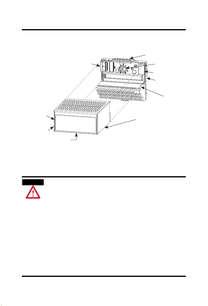
Module Installation
Install the Module
This module must be used with a 1797-TB3 or 1797-TB3S intrinsically-safe
terminal base unit.
This equipment is considered Group 1, Class A industrial equipment
according to IEC/CISPR Publication 11. Without appropriate
precautions, there may be potential difficulties ensuring
electromagnetic compatibility in other environments due to
conducted as well as radiated disturbance.
This equipment is supplied as open-type equipment. It must be
mounted within an enclosure that is suitably designed for those
specific environmental conditions that will be present and
appropriately designed to prevent personal injury resulting from
accessibility to live parts. The interior of the enclosure must be
accessible only by the use of a tool. Subsequent sections of this
publication may contain additional information regarding specific
enclosure type ratings that are required to comply with certain
product safety certifications.
Publication
1797-5.9 - June 2010
Page 4
4 FLEX Ex Frequency Input Module
ATTENTION
20128-M
1. Rotate keyswitch (1) on terminal base unit (2) clockwise to position 1 as
required for this type of module.
Do not change the position of the keyswitch after wiring the
terminal base unit.
2. Make certain the flexbus connector (3) is pushed all the way to the left to
connect with the neighboring terminal base/adapter.
You cannot install the module unless the connector is fully
extended.
3. Make sure the pins on the bottom of the module are straight so they will
align properly with the connector in the terminal base unit.
4. Position the module (4) with its alignment bar (5) aligned with the groove
(6) on the terminal base.
5. Press firmly and evenly to seat the module in the terminal base unit. The
module is seated when the latching mechanism (7) is locked into the
module.
6. Make certain that you only connect terminal base units to other
intrinsically safe system modules or adapters to maintain the integrity of
the intrinsically-safe backplane.
7. Remove cap plug (8) and attach another intrinsically safe terminal base
unit to the right of this terminal base unit if required.
Installation in Zone 1
This module must not be exposed to the environment. Provide a suitable
metal enclosure. This module has a protection factor of IP20.
This module cannot be used in an intrinsically safe
environment after it has been exposed to non-intrinsically
safe signals.
Publication
1797-5.9 - June 2010
Page 5

FLEX Ex Frequency Input Module 5
Installation in Zone 22
When the module is installed in Zone 22, the following cabinets must be used:
IVK-ISRPI-V16LC; IVK-ISRPI-V8HYW; or IVK-ISRPI-V8LC. These
cabinets can be purchased from Pepperl+Fuchs GmbH, Lilienthalstrasse 200,
68307 Mannheim, Germany. Information aavailable at
http://www.pepperl-fuchs.com
The IS-RPI cabinets (type IVK2-ISRPI-V8LC, IVK2-ISRPI-V8HYW, or
IVK2-ISPRI-V16LC) ensures the basic protection for the intrinsically safe
apparatus of the FLEX Ex system for use in Zone 22. It corresponds with
category 3D according to RL 94/9 EG and with the type label marked with
the following information:
Pepperl+Fuchs GmbH
68307 Mannheim
IVK2-ISRPI-V8LC (or IVK2-ISRPI-V8HYW or
IVK2-ISRPI-V16LC)
II 3 D Ex tD A22 IP54 T70 °C X
CE
Serial (manufacturing) number
Model
Electrostatic Charge
Protect the system against electrostatic charge. Post a sign near this module:
WARNING Avoid electrostatic charging.
ADVERTÊNCIA! PREVENIR CONTRA O ACÚMULO DE CARGA
ELETROSTÁTICA.
For your convenience, a sign which can be cut out and posted is included in
this installation instruction.
.
Publication
1797-5.9 - June 2010
Page 6

6 FLEX Ex Frequency Input Module
WARNING
Removal and Insertion Under Power
These modules are designed so you can remove and insert them
under power. However, take special care when removing or
inserting modules in an active process. I/O attached to any module
being removed or inserted can change states due to its input/output
signal changing conditions.
If you insert or remove the terminal base unit while backplane power
is on, an electrical arc can occur. This could cause an explosion in
hazardous location installations.
Be sure that power is removed or the area is nonhazardous before
proceeding.
European Community Directive Compliance
If this product has the CE mark it is approved for installation within the
European Union and EEA regions. It has been designed and tested to meet
the following directives.
EMC Directive
These products are tested to meet the Council Directive 2004/108/EC by
applying the following standards:
EN 61000-6-4:2007, Electromagnetic Compatibility (EMC) - Part 6-4:
Generic Standard for Industrial Environments (Class A)
EN 61000-6-2:2005, Electromagnetic Compatibility (EMC) - Part 6-2:
Generic Standards - Immunity for Industrial Environments
EN61326-1:2006 (Industrial), Electrical Equipment For
Measurement, Control, and Laboratory Use - Industrial EMC
Requirements
Publication
1797-5.9 - June 2010
Page 7

FLEX Ex Frequency Input Module 7
IMPORTANT
ATEX Directive
These products are tested in conjunction with associated I/O modules to
meet the Council Directive 94/9/EC (ATEX) Equipment and Protective
Systems Intended for Use in Potentially Explosive Atmospheres by applying
the following standards:
EN60079-11:2007, Explosive atmospheres - Part 11 : equipment
protection by intrinsic safety "i"
EN60079-0:2006, Electrical apparatus for explosive gas atmospheres -
Part 0 : general requirements
EN 60079-26 : 2004, Electrical apparatus for explosive gas
atmospheres - Part 26 : construction, test and marking of Group II
Category 1 G electrical apparatus
EN61241-0 : 2006, Electrical apparatus for use in the presence of
combustible dust - Part 0: General requirements
EN61241-11:2006, Electrical apparatus for use in the presence of
combustible dust – Part 11: Protection by intrinsic safety 'iD'
Inputs
The frequency input module has 2 input channels. Each input can accept
inputs from magnetic pickups or proximity probes. Each input channel has 2
input selections: frequency input or gate input. Do not apply any
nonintrinsically safe signals to this module.
The channels in this module are electrically connected to each other.
When using an intrinsically safe electrical apparatus according to EN
60079-11, the European directives and regulations must be followed.
When interconnecting several lines, you must consider the total
accumulated power and check for intrinsic safety.
Publication
1797-5.9 - June 2010
Page 8
8 FLEX Ex Frequency Input Module
Power
Supply
flexbus
+V
Bus
uC
-V
V+
6V
3V
+8V
50mV select
N
500/50mV
GND
+8V
N
GND
R NO
R Com
R NC
Solenoid
NAMUR
Prox
NAMUR
Prox
NAMUR
Prox
Valve
Audible
Alarm
Vort e x
sensor
jumper for 50mV sensor
none for 500mV
magnetic
sensor
jumper for 50mV sensor
none for 500mV
50mV select
500/50mV
CH GND
CH GND
magnetic
sensor
*
*
***
*
For VORTEX and magnetic pickups only - jumper from GND to CH GND.
41302
Publication
1797-5.9 - June 2010
Page 9
FLEX Ex Frequency Input Module 9
ATTENTION
WARNING
41506
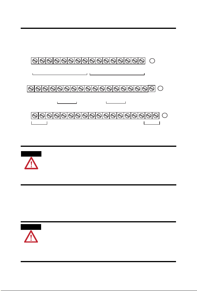
Wire to a 1797-TB3 or 1797-TB3S Terminal Base Unit
Connect wiring to the terminal base as shown below.
0 1 2 3 4 5 6 7 8 9 10 11 12 13 14 15
3V 6V V+ GND 50
16
Chassis
GND
34
+V -V +V -V
Connections for Terminal Base 1797-TB3 shown
500/50
8V 8V
mV
mV
Channel 0 Frequency Input Channel 1 Frequency Input
17 18 19 20 21 22 23 24 25 26 27 28 29 30 31 32 33
R0NOR0
35 36 37 38 39 40 41 42 43 44 45 46 47 48 49 50 51
Sel
GND N N GND
50
NC
No connections allowed to terminals 19, 30, 36, 38, 39, 47, 48, 49
500/50
mV
mV
Sel
Channel 0 Gate Input Channel 1 Gate Input
R0
COM
8V 8V
500/50mV50
500/50mV50
mV
Sel
mV
Sel
R1
COM
R1NOR1
For VORTEX signals and magnetic pickups only.
Connect the channel ground terminals to the chassis ground terminals to
achieve the EMC protection class. Because, in this case, the intrinsically safe
circuit is grounded, and you must check the installation requirements of the
respective country for this context.
A
3V6VV+GNDNN
B
Chassis
GND
NC
C
Wire the Module
Make wiring connections to the module terminal base unit according to the
wiring table below.
Make certain that you power this module with an intrinsically safe power
supply. Do not exceed the values listed in the specifications for this module.
If you connect or disconnect wiring while the field-side power is on, an
electrical arc can occur. This could cause an explosion in hazardous location
installations. Be sure that power is removed or the area is nonhazardous
before proceeding.
Publication
1797-5.9 - June 2010
Page 10
10 FLEX Ex Frequency Input Module
Type of Input
Channel 0 Terminations
Power Input
4
Channel 1 Terminations
5
GND
Power
Input
1
Frequency
NAMUR Proximity
Contact Switch
1
2
76 8 9
76 8 9
500 mV ac Magnetic Pickup 5 3 10 12
50 mV ac Magnetic Pickup
3
5 3 10 12
6V ac Vortex 2 1 3 13 14 12
3V ac Vortex 2 0 3 13 15 12
Gate
NAMUR Proximity
Contact Switch
1
2
24 23 25 26
24 23 25 26
500 mV ac Magnetic Pickup 22 20 27 29
50 mV ac Magnetic Pickup
1 As defined by standard DIN 19234.
2 Add external resistor across field device for wire-off detection (0.4 mA) - (about 15
3 Add a jumper between 50 mV Sel and N (frequency - channel 0 = 4
gate - channel 0 = 21 to 23, channel 1 = 28
4 Connect cable shields to shield busbar or shield terminating feedthroughs.
5 All GND terminals are internally connected together.
3
22 20 27 29
…20 K).
to 26).
to 6, channel 1 = 9 to 11;
Relay Connections
Channel 0 Relay Connections Channel 1 Relay Connections
COM 37 COM 46
N.O. 17 N.O. 31
N.C. 18 N.C. 32
4
GND
5
Publication
1797-5.9 - June 2010
Page 11

FLEX Ex Frequency Input Module 11
ATTENTION
30820-M
Ground the Module
Do not use the unused terminals on this terminal base unit.
Using these terminals as supporting terminals can result in
damage to the module and/or unintended operation of your
system.
All I/O wiring must use shielded wire. Shields must be terminated external to
the module, such as bus bars and shield-terminating feedthroughs.
Publication
1797-5.9 - June 2010
Page 12

12 FLEX Ex Frequency Input Module
41300
Indicators
Allen-Bradley
FREQUENCY INPUT 2 CHANNEL
1797-IJ2
GATE 0 GATE 1IN 0 IN 1 OUT 0 OUT 1
A
B
A = Status Indicators for individual channels
B = Insertable labels for writing individual I/O designations
C = Power Indicator - green indicates power applied to module
Indicator
Input (0 or 1)
Frequency or Gate
Output Alarm (0 or 1) Off/Dark Output turned off.
Module Power (OK) Off/Dark +V power off, or 5V logic power problem.
Input 0 Red Power up check running.
Indication Description
Off/Dark Input turned off, input not used, wire disconnected.
On/Yellow Input turned on. Wire connected, normal operation.
Blinking Red Wire disconnected, fault condition (for NAMUR
On/Yellow Output turned on (logic drive on).
Solid Green Power applied to module.
proximity switch or switch contacts with shunt
resistor).
Ex
1
PWR
C
Publication
1797-5.9 - June 2010
Page 13

FLEX Ex Frequency Input Module 13
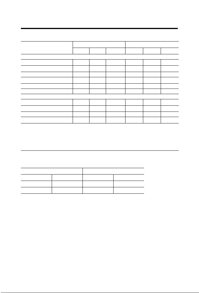
Resolution and Accuracy
Accuracy
Minimum
Frequency
Sampling
Time in ms
2+
4+
5+
10 +
20 +
50 +
100 +
200 +
500 +
1000 +
Sampling
Accuracy
0.02% +0.0225% +0.0425%
0.01% +0.0225% +0.0325%
0.008% +0.0225% +0.0305%
0.004% +0.0225% +0.0265%
0.002% +0.0225% +0.0245%
0.0008% +0.0225% +0.0233%
0.0004% +0.0225% +0.0229%
0.0002% +0.0225% +0.0227%
0.00008% +0.0225% +0.02258%
0.00004% +0.0225% +0.02254%
Time Base
Accuracy
Worst Case
Accuracy
Deviation in Hz Due to
Total Accuracy
1.0…3276.7
Freq. Range
(Hz)
+
0.1…1.4 +1…14
+
0.1…1.1 +1…10
+
0.1…1.0 +1…10
+
0.1…0.9 +1…9
+
0.1…0.8 +1…8
+
0.1…0.8 +1…8
+
0.1…0.8 +1…8
+
0.1…0.7 +1…7
+
0.1…0.7 +1…7
+
0.1…0.7Hz +1…7
1…32767
Range (Hz)
Freq.
Input Map
Bit
15 14 13 12 11 10 09 08 07 06 05 04 03 02 01 00
Word
0 Frequency 0…32,767 or 0.0…3,276.7 Channel 0
1
2
3
4
5
6
Where: GS = Gate state
% Full Scale 0.0
% Full Scale 0.0
R Direction
R
Ch 0
Reserved
F/A = Frequency/Accel alarm
WO = Wire-off alarm
MPA = Missing pulse alarm
R = Reserved
…3,276.7% Channel 0 or Acceleration -32,768…32,767 Channel 0
Frequency 0
…3,276.7% Channel 1 or Acceleration -32,768…32,767 Channel 1
GS
F/A
Ch
Ch 0
0
Diagnostic Status
Channel 0
Read
…32,767 or 0.0…3,276.7 Channel 1
WO
MPA
Ch 0
R R Direction
Ch 0
Reserved
Ch 1GSCh
Reserved Diagnostic Status
Publication
1
Channel 1
1797-5.9 - June 2010
Resolution
0.01%
0.005%
0.004%
0.002%
0.001%
0.0004%
0.0002%
0.0001%
0.00004%
0.00002%
F/A
Ch
1
(%)
WO
Ch
1
MP
A
Ch 1
Page 14

14 FLEX Ex Frequency Input Module
Output Map
Bit 15 14 13 12 11 10 09 08 07 06 05 04 03 02 01 00
MPM
Ch 0
Write
Alt
Pulse
Ter m
Init
St Up
Ch 0
Init
St Up
Ch 1
Reserved
LF FR
ACT
0…3
Ch 0
ACT
0…3
Ch 1
Ch
1
Number of
Pulses to
terminate
sampling Ch 1
F/A
MPDM
AS
Ch 0
Ch 0
F/A
MPDM
AS
Ch 1
Ch 1
MPM
Ch 1
WOFM
Ch 0
WOFM
Ch 1
Word
Out
0
Enb
FSM FR
Ch
0
Number of
Pulses to
terminate
sampling Ch 0
1 Maximum Frequency 0…32,767 or 0.0…3,276.7 or
Absolute Value of Acceleration 0…32,767 - Channel 0
2 Frequency Scaling Divisor 1…255 Ch 0 Frequency Scaling Multiplier 1…255 Ch 0
WO
WO
IGI
IFI
3
FG
FF
Ch 0
Ch
0
Ch
0
4 Maximum Frequency 0…32,767 or 0.0…3,276.7 or
Minimum
Ch
Frequency Sample
0
Time
Ch 0
Absolute Value of Acceleration 0…32767 - Channel 1
5 Frequency Scaling Divisor 1…255 Ch 1 Frequency Scaling Multiplier 1…255 Ch 1
WO
WO
IGI
IFI
6
FG
FF
Ch 1
Ch
1
Ch
1
Minimum
Ch
Frequency Sample
1
Time
Ch 1
7
Where: Out Enb = Output enable
FSM = Fault state mode
FR = Frequency range
MPM = Missing pulse multiplier
LF = Local fault mode
F/AAS = Frequency/Accel alarm select
WOOF = Wire-off fault frequency
WOFG = Wire-off fault gate
WOFM = Wire-off fault mode
IGI = Invert gate input
FI = Invert frequency input
ACT = Acceleration calculation time
MPDM = Missing pulse delay multiplie r
Alt Pulse Term = Alternate Number of Pulses to terminate sampling
Repair
This module is not field-repairable. Any attempt to open this module will void
the warranty and IS certification. If repair is necessary, return this module to
the factory.
Publication
1797-5.9 - June 2010
Page 15

FLEX Ex Frequency Input Module 15
Specifications
Specifications - 1797-IJ2 Frequency Input Module
Number of inputs 2 frequency channels
IS input type Ex ia IIB/IIC T4
IS module type Ex ib IIB/IIC T4
Input (intrinsically safe) to DIN19234
(NAMUR)
No load voltage short circuit
current
Switching point/switching
hysteresis
Input pulse length/pulse pause
Lead breakage monitoring
Inputs to flowmeter
Input signal
Voltage available at 20 mA
Inputs to magnetic pickup input
signal
Processing time
Input frequency 1.0…32,767 Hz
Resolution and accuracy Minimum Frequency Resolution
Specifications continued on next page.
2 gate channels
AEx ia IIC T4
Class I, II, III Division 1 Group A to G T4
AEx ib IIC T4
Class I, Division 1 Group A to D T4
8V dc/8 mA
1.2…2.1 mA/0.2 mA
>20 s/>20 s
Breakage current <0.35 mA
Threshold 3V or 6V selectable
>15V
50 mV or 500 mV selectable
4 ms
Sampling Time (ms) Accuracy (%)
2 0.043
4 0.033
5 0.031
10 0.027
20 0.025
50 0.023
100 0.023
200 0.023
500 0.023
1000 0.023
Publication
1797-5.9 - June 2010
Page 16

16 FLEX Ex Frequency Input Module
Frequency input characteristics Magnetic pickup: 50 mV, 500 mV
NAMUR: 8V, 8 mA
Flowmeter: low <
Frequency input impedance rating >5 k magnetic pickup
>10 Kflowmeter
Outputs 2 relay outputs
Output switching time <10 ms
Gate inputs 2
Input (intrinsically safe) to DIN19234
(NAMUR)
No load voltage short
8V dc/8 mA
Circuit current
Switching point/
1.2…2.1 mA/0.2 mA
Switching hysteresis
Input pulse length/
>20 s/>20 s
Pulse pause
Lead breakage monitoring
Breakage current <0.35 mA
Indicators 6 yellow status indicators
4 red fault indicators
1 green module power indicator
Output (intrinsically safe)
(16 pin male and female Flexbus
connector)
Isolation path
Input to power supply
Input to Flexbus
Input to input
Output to power supply
Output to Flexbus
Output to output
Power supply
(+V, -V intrinsically safe)
Module field-side power
U
< 5.8V
o
I
< 400 mA
o
L
< Negligible
i
C
< 2.64 F
i
Isolation Type
Galvanic to DIN EN 60079-11
Galvanic to DIN EN 60079-11
None
Galvanic to DIN EN 60079-11
Galvanic to DIN EN 60079-11
Galvanic to DIN EN 60079-11
U
< 9.5V dc
i
I
< 1 A
i
L
= Negligible
i
C
= Negligible
i
4.25 W
consumption
Power dissipation 4.25 W
Specifications continued on next page.
3V, high >6V
Publication
1797-5.9 - June 2010
Page 17

FLEX Ex Frequency Input Module 17
Thermal dissipation, max 14.5 BTU/hr
Module location Cat. No. 1797-TB3 or 1797-TB3S Terminal Base Unit
Conductor wire size 4 mm
Dimensions,approx. (HxWxD) 46 x 94 x 75 mm
Weight, approx. 200 g
Keyswitch position 1
Environmental conditions
Operational temperature
Storage temperature
Relative humidity
Shock Operating
Nonoperating
Vibration
Agency certification
CENELEC
UL, C-UL
FM
INMETRO
IECEx
Certificate of conformity
CENELEC
UL, C-UL
FM
INMETRO
IECEx
2
(12 gauge ) stranded max
1.2 mm (3/64 in.) insulation max
(1.8 x 3.7 x 2.95 in.)
°
-20…70
C (-4…158 °F)
°
-40…85
C (-40…185 °F)
5…95% noncondensing
Tested to 15 g peak acceleration, 11(+1) ms pulse width
Tested to 15 g peak acceleration, 11(+1) ms pulse width
Tested 2 g @ 10…500 Hz per IEC68-2-6
II (1) 2G Ex ib[ia] IIC T4
II (1) D [Ex iaD]
Class I, Groups A, B, C and D; Class II, Groups E, F and G;
Class III hazardous Locations.
Class I, Zone 1, AEx ib[ia] IIC T4.
Intrinsically safe Class I, Div 1, Groups A, B, C, D, T4.
Associated Apparatus with intrinsically safe
connections Class I, II, III, Div 1, Groups A--G
Intrinsically safe Class I, Zone 1, AEx ib[ia] IIC T4.
BR-Ex ia/ib IIB/IIC T4
[Zone 0] Ex ib[ia] IIC T4
[Ex iaD]
DMT 98 ATEX 033 X
UL, C-UL File Number E197983
FM Certificate Number 3009806
05/UL-BRAE-0014X
IECEx BVS 09.0028X
Publication
1797-5.9 - June 2010
Page 18

18 FLEX Ex Frequency Input Module
CE/CENELEC I/O Entity Parameters
Channel 0 Frequency Input
Field devices may only be connected to the terminals of one of the five
following circuits. The terminals of the remaining four circuits must not be
connected.
Namur/
Contact
(Terminals
6…7)
Uo = 14.7V
= 15 mA
I
o
= 30 mW
P
o
Protection Group Allowed
Ex ia IIB 3.86 F 300 mH 2.6 mH/
Magnetic 500 mV
(Terminals 5…3)
Uo = 14.7V
= 10 mA
I
o
= 18 mW
P
o
Magnetic 50 mV
(Terminals 5…3,
6…4)
Uo = 14.7V
= 10 mA
I
o
= 18 mW
P
o
Vortex 6V
(Terminals
1, 2…3)
Uo = 26.5V
= 82 mA
I
o
= 520 mW
P
o
Vortex 3V
(Terminals
Ex ia IIB 730 nF 8 mH 0.26 mH/
0, 2…3)
Uo = 26.5V
= 82 mA
I
o
= 520 mW
P
o
Ex ia IIB 730 nF 8 mH 0.26 mH/
Capacitance
IIC 620 nF 80 mH 0.65 mH/
Protection Group Allowed
Capacitance
Ex ia IIB 3.86 F 600 mH 4.15 mH/
IIC 620 nF 150 mH 1.03 mH/
Protection Group Allowed
Ex ia IIB 3.86 F 600 mH 4.15 mH/
Capacitance
IIC 620 nF 150 mH 1.03 mH/
Protection Group Allowed
Capacitance
IIC 95 nF 2 mH 0.06 mH/
Protection Group Allowed
IIC 95 nF 2 mH 0.06 mH/
Capacitance
Inductance
Allowed
Inductance
Allowed
Inductance
Allowed
Inductance
Allowed
Inductance
Allowed
LoR
Ratio
LoR
Ratio
LoR
Ratio
LoR
Ratio
LoR
Ratio
o
o
o
o
o
Publication
1797-5.9 - June 2010
Page 19

FLEX Ex Frequency Input Module 19
Channel 1 Frequency Input
Field devices may only be connected to the terminals of one of the five
following circuits. The terminals of the remaining four circuits must not be
connected.
Namur/
Contact
(Terminals
9…8)
Uo = 14.7V
= 15 mA
I
o
= 30 mW
P
o
Protection Group Allowed
Ex ia IIB 3.86 F 300 mH 2.6 mH/
Magnetic 500 mV
(Terminals
10…12)
Uo = 14.7V
= 10 mA
I
o
= 18 mW
P
o
Magnetic 50 mV
(Terminals
10…12, 9…11)
Uo = 14.7V
= 10 mA
I
o
= 18 mW
P
o
Vortex 6V
(Terminals
14, 13…12)
Uo = 26.5V
= 82 mA
I
o
= 520 mW
P
o
Ex ia IIB 730 nF 8 mH 0.26 mH/
Capacitance
IIC 620 nF 80 mH 0.65 mH/
Protection Group Allowed
Capacitance
Ex ia IIB 3.86 F 600 mH 4.15 mH/
IIC 620 nF 150 mH 1.03 mH/
Protection Group Allowed
Ex ia IIB 3.86 F 600 mH 4.15 mH/
IIC 620 nF 150 mH 1.03 mH/
Capacitance
Protection Group Allowed
Capacitance
IIC 95 nF 2 mH 0.06 mH/
Inductance
Allowed
Inductance
Allowed
Inductance
Allowed
Inductance
Allowed
LoR
Ratio
LoR
Ratio
LoR
Ratio
LoR
Ratio
o
o
o
o
Vortex 3V
(Terminals
15, 13…12
Uo = 26.5V
= 82 mA
I
o
= 520 mW
P
o
Protection Group Allowed
Capacitance
Ex ia IIB 730 nF 8 mH 0.26 mH/
IIC 95 nF 2 mH 0.06 mH/
Allowed
Inductance
Publication
LoR
Ratio
1797-5.9 - June 2010
o
Page 20

20 FLEX Ex Frequency Input Module
Channel 0 Gate Input
Field devices may only be connected to the terminal of one of the three
following circuits. The terminals of the remaining two circuits must not be
connected.
Namur/
Contact
(Terminals
Protection Group Allowed
23…24)
Uo = 14.7V
= 15 mA
I
o
P
= 30 mW
o
Ex ia IIB 3.86 F 300 mH 2.6 mH/
Magnetic 500 mV
(Terminals
22…20)
Uo = 14.7V
= 10 mA
I
o
= 18 mW
P
o
Magnetic 50 mV
(Terminals
22…20, 23…21)
Uo = 14.7V
= 10 mA
I
o
= 18 mW
P
o
e
Allowed
Inductance
Allowed
Inductance
Allowed
Inductance
Capacitance
IIC 620 nF 80 mH 0.65 mH/
Protection Group Allowed
Capacitance
Ex ia IIB 3.86 F 600 mH 4.15 mH/
IIC 620 nF 150 mH 1.03 mH/
ProtectionGroup Allowed
Capacitanc
Ex ia IIB 3.86 F 600 mH 4.15 mH/
IIC 620 nF 150 mH 1.03 mH/
LoR
Ratio
LoR
Ratio
LoR
Ratio
o
o
o
Publication
1797-5.9 - June 2010
Page 21

FLEX Ex Frequency Input Module 21
Channel 1 Gate Input
Field devices may only be connected to the terminals of one of the three
circuits. The terminals of the remaining two circuits must not be connected.
Namur/
Contact
(Terminals
Protection Group Allowed
26…25)
Uo = 14.7V
= 15 mA
I
o
= 30 mW
P
o
Magnetic 500 mV
Ex ia IIB 3.86 F 300 mH 2.6 mH/
Protection Group Allowed
(Terminals 27…29)
Uo = 14.7V
= 10 mA
I
o
= 18 mW
P
o
Magnetic 50 mV
(Terminals
27…29, 26…28)
Uo = 14.7V
= 10 mA
I
o
= 18 mW
P
o
Ex ia IIB 3.86 F 600 mH 4.15 mH/
Protection Group Allowed
Ex ia IIB 3.86 F 600 mH 4.15 mH/
Relay Output Parameters
Relay Output
(Terminals 17, 18,
37, or 31, 32, 46)
Ui = 28V
= 93 mA
I
i
= 651 mW
P
i
Protection Group Internal
Ex ia IIB Negligible Negligible
Capacitance
IIC 620 nF 80 mH 0.65 mH/
Allowed
Inductance
LoR
Ratio
Allowed
Capacitance
IIC 620 nF 150 mH 1.03 mH/
Capacitance
IIC 620 nF 150 mH 1.03 mH/
Inductance
Allowed
Inductance
Ratio
LoR
Ratio
Internal
Capacitance
IIC Negligible Negligible
Inductance
o
LoR
o
o
UL, C-UL I/O Entity Parameters
If the product has the UL/C-UL mark, it has been designed, evaluated, tested,
and certified to meet the following standards:
Publication
1797-5.9 - June 2010
Page 22

22 FLEX Ex Frequency Input Module
UL 913, 1988, Intrinsically Safe Apparatus and Associated Apparatus
for use in Class I, II, and III Division 1, Hazardous (Classified)
Locations
UL 1203, Explosion-Proof and Dust-Ignition-Proof Electrical
Equipment for Use in Hazardous (Classified) Locations
UL 2279, Electrical Equipment for Use in Class I, Zone 0, 1, and 2
Hazardous (Classified) Locations
UL 61010, UL Standard for Safety Electrical Equipment For
Measurement, Control, and Laboratory Use; Part 1: General
Requirements
CSA C22.2 No. 157-92, Intrinsically Safe and Non-Incindive
Equipment for Use in Hazardous Locations
CSA C22.2 No. 30-M1986, Explosion-Proof Enclosures for Use in
Class I Hazardous Locations
CSA-E79-0-95, Electrical Apparatus for Explosive Gas Atmospheres,
Part 0: General Requirements
CSA-E79-11-95, Electrical Apparatus for Explosive Gas
Atmospheres, Part 11: Intrinsic Safety “i”
CSA C22.2 No. 14-95, Industrial Control Equipment
Publication
1797-5.9 - June 2010
Page 23

Table 1
Wiring
Method
1 and 2 Any one
1 and 2 Any one
1 and 2 Any one
1 and 2 Any one
Method
Channel Terminals Voc
channel
channel
channel
channel
Wiring
1 and 2 Any one
Channel Terminals V
channel
6, 7;
9, 8;
23, 24
26, 25
5, 3;
10, 12;
22, 20;
27, 29
5, 3, 6, 4;
10, 12, 9, 11;
22, 20, 21,
23; 27, 29,
26, 28
0, 2, 3;
1, 2, 3;
14, 12, 13;
15, 12, 13
17, 18, 37
31, 32, 46
FLEX Ex Frequency Input Module 23
Isc
Vt
It
(V)
(mA)
(V)
14.7 15.0 - - A, B 0.62 80.0
14.7 10.0 - - A, B 0.62 150.0
14.7 10.0 - - A, B 0.62 150.0
26.5 82.0 - - A, B 0.095 2.0
I
max
max
(V)
(mA)
or
28 93.0 A, B 0.0 0.0
Groups Ca
(mA)
Groups Ci (F) Li (mH)
C, E 0.0 0.0
D, F, G 0.0 0.0
(F)
C, E 1.82 320.0
D, F, G 4.96 640.0
C, E 1.82 600.0
D, F, G 4.96 1200.0
C, E 1.82 600.0
D, F, G 4.96 1200.0
C, E 0.285 8.0
D, F, G 0.76 16.0
La
(mH)
Wiring Methods
Wiring method 1 - Each channel is wired separately.
Wiring method 2 - Multiple channels in one cable, providing each
channel is separated in accordance with the National Electrical Code
(NEC) or Canadian Electrical Code (CEC).
Publication
1797-5.9 - June 2010
Page 24

24 FLEX Ex Frequency Input Module
WARNING
AVERTISSEMENT
IMPORTANT
Table 2
Ter mi na ls Vt (V) It (mA) Groups Ca (F) La (H)
Male Bus Connector 5.8 400 A-G 3.0 3.0
The entity concept allows interconnection of intrinsically safe apparatus
with associated apparatus not specifically examined in combination as a
system when the approved values of Vt and It of the associated apparatus are
less than or equal to Voc and Isc or V
max
and I
of the intrinsically safe
max
apparatus and the approved values of Ca and La of the associated apparatus
are greater than Ci + C
and Li + L
cable
respectively for the intrinsically safe
cable
apparatus. The internal capacitances Ci of the terminal base must be taken
into account to verify the intrinsic safety.
Simple apparatus is defined as a device which neither generates nor
stores more than 1.2V, 0.1 A, 20 J, or 25 mW.
Wiring methods must be in accordance with the National Electrical
Code, ANSI/NFPA 70, Article 504 and 505 or the Canadian Electrical Code
CSA C22.1, Part 1, Appendix F. For additional information refer to
ANSI/ISA RP12.6.
This module, 1797-IJ2, must be used with terminal base 1797-TB3 or
1797-TB3S.
Terminals 19, 30, 36, 38, 39, and 47…49 shall not be connected.
Substitution of components may impair intrinsic safety
Publication
La substitution de composant peut compromettre la securite
intrinseque.
For detailed certification information, refer to the FLEX Ex System
Certification Reference Manual, publication 1797-6.5.6
1797-5.9 - June 2010
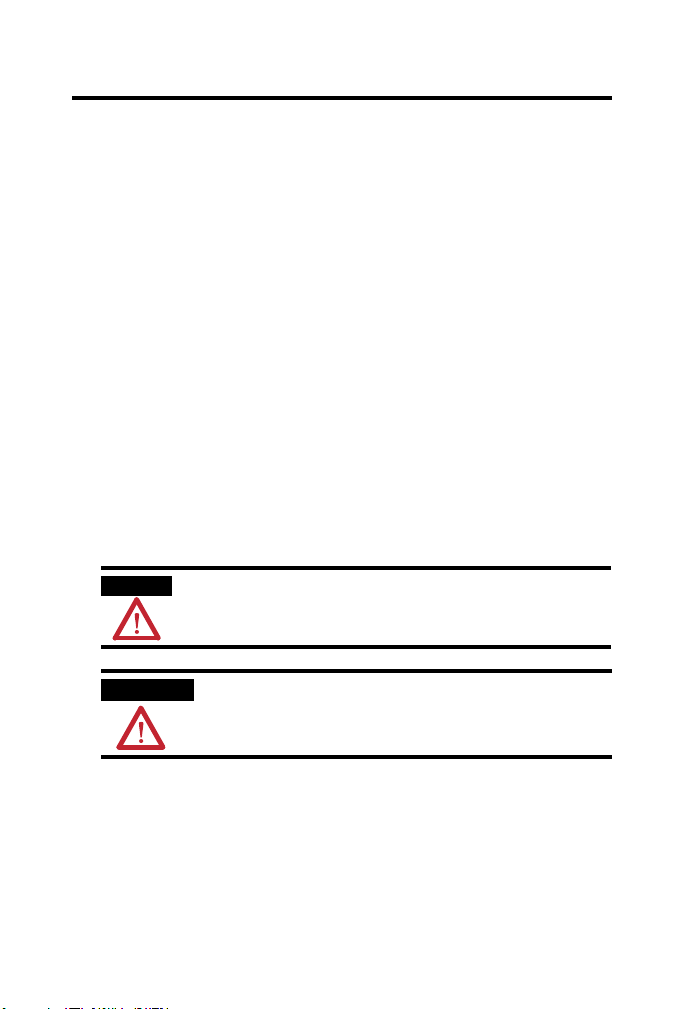
Page 25

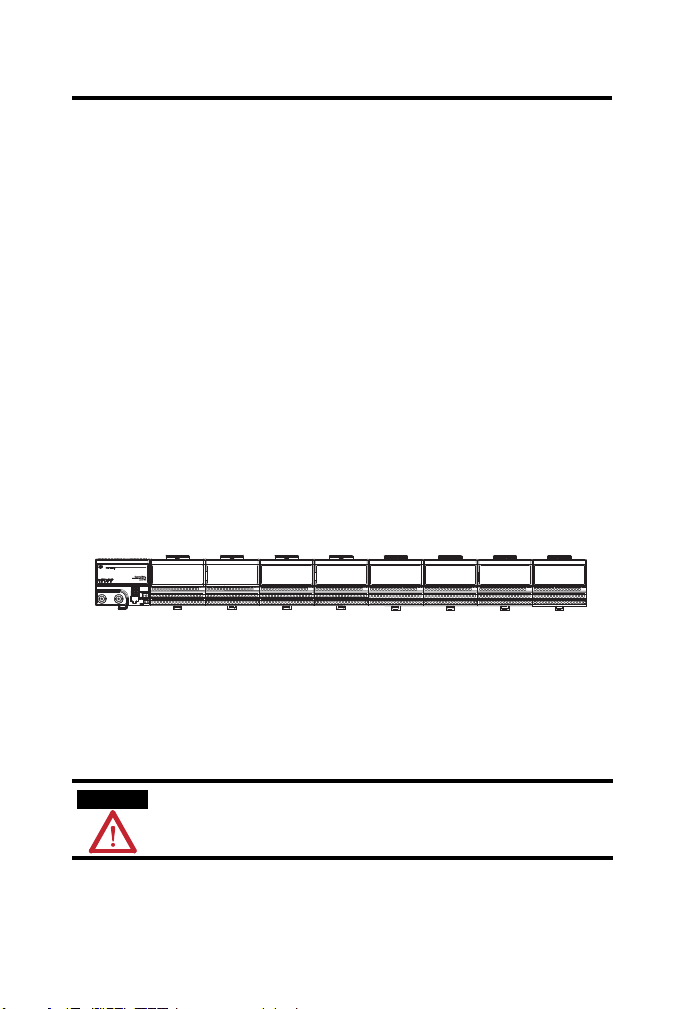
B-A
FLEX Ex Frequency
Input I/O Module
Indicators
Female Bus
Connection
Field Wiring
Terminals
Terminal Base
Terminal Base
Key
Male Bus
Connection
Key Position for
Terminal Base
Insertion
IMPORTANT
The terminal base unit may or may not have an I/O module installed
42066
Allen-Bradley
2 Point Frequency Input Module
FLEX Ex Frequency Input Module 25
1797- IJ2
1
7PWR6543210
Publication
1797-5.9 - June 2010
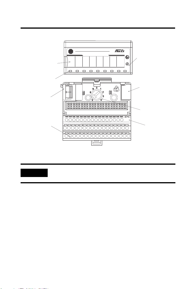
Page 26

26 FLEX Ex Frequency Input Module
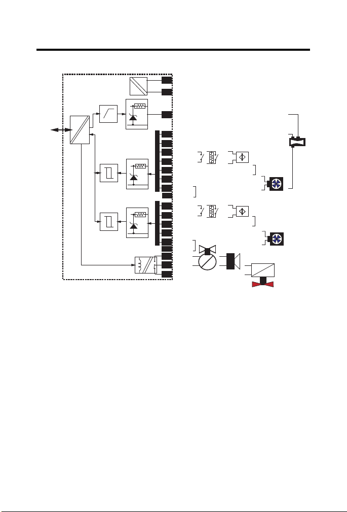
Hazardous (Classified) Location
Class I, Zones 0, 1, & 2 Groups IIC,
IIB, IIA
Class I, Div. 1 & 2 Groups A, B, C, D
Class II, Div. 1 & 2 Groups E, F, G
Class III, Div. 1 & 2
Hazardous (Classified) Location
Class I, Zones 1 & 2 Groups IIC, IIB, IIA
Class I, Div. 1 & 2 Groups A, B, C, D
To any intrinsically safe
device or associated
apparatus with Entity
Concept parameters of
V
oc
< 5.8V; Isc < 400 mA.
To any intrinsically safe
device or associated
apparatus with Entity
Concept parameters of
V
oc
< 9.5V; Isc < 1 A.
To any IS device with Entity
Concept parameters of
(V
max
, I
max
, Ci, Li) appropriate
for connection to associated
apparatus with Entity Concept
parameters listed in Table 2.
1797-IJ2
16
Shield connection only.
50
51
35
34
V
max
=5.8V
I
max
=400mA
Ci=2640nF
Li=negligible
V
max
=9.5V
I
max
=1A
Ci=negligibl
Male Bus
Connecto
33
40
41
42
43
44
45
0
Female
Bus
1
2
3
4
5
6
7
8
9
10
11
12
13
14
15
20
21
22
23
24
25
26
27
28
29
V
max
=28V
I
max
=93mA
Ci=negligible
Li=negligible
V
max
=28V
I
max
=93mA
Ci=negligible
Li=negligible
17
18
37
31
32 46
To any intrinsically safe device
or associated apparatus with
Entity Concept parameters
of Voc < 28V; Isc < 93 mA.
To any intrinsically safe device
or associated apparatus with
Entity Concept parameters
of V
oc
< 28V; Isc < 93 mA.
ch0
Freq. In
ch1
Freq. In
Any Simple Apparatus or
I.S. device with Entity
Concept parameters (V
max
,
I
max
, Ci, Li) appropriate for
connection to associated
apparatus with Entity Concept
parameters listed in Table 1.
ch0
Gate
ch1
Gate
Any Simple Apparatus or I.S.
device with Entity Concept
parameters (V
max
, I
max
, Ci, Li)
appropriate for connection to
associated apparatus with
Entity Concept parameters
listed in Table 1.
FM Input I/O Entity Parameters
If this product has the FM mark, it has been designed, evaluated, tested and
certified to meet the following standards:
FM C1. No 3600:1998, Electrical Equipment for Use in Hazardous
(Classified) Locations General Requirements
Publication
1797-5.9 - June 2010
Page 27

FLEX Ex Frequency Input Module 27
FM C1. No 3610:1999, Intrinsically Safe Apparatus and Associated
Apparatus for Use in Class I, II, III Division 1 Hazardous (Classified)
Locations
FM C1. No 3615:1989, Explosionproof Electrical Equipment General
Requirements
FM C1. No 3810:1989, 1995, Electrical and Electronic Test,
Measuring and Process Control Equipment
ANSI/NEMA 250, 1991, Enclosures for Electrical Equipment
Wiring Methods
Wiring method 1 - Each channel is wired separately.
Wiring method 2 - Multiple channels in one cable, providing each
channel is separated in accordance with the National Electrical Code
(NEC).
Publication
1797-5.9 - June 2010
Page 28

28 FLEX Ex Frequency Input Module
Table 1
Wiring
Method
1 and 2 Any one
1 and 2 Any one
1 and 2 Any one
1 and 2 Any one
Channel Terminals Voc
channel
6, 7;
9, 8;
23, 24
(V)
14.7 15.0 - - A, B 0.65 130.0
26, 25
channel
5, 3;
10, 12;
22, 20;
14.7 10.0 - - A, B 0.65 300.0
27, 29
channel
channel
5, 3, 6, 4;
10, 12, 9, 11;
22, 20, 21,
23;
27, 29, 26,
0, 2, 3;
1, 2, 3;
14, 12, 13;
14.7 10.0 - - A 0.65 300.0
28
26.5 82.0 - - A, B 0.13 4.5
15, 12, 13
Isc
(mA)
Vt (V) It
(mA)
Groups Ca
La (mH)
(F)
C, E 1.95 390.0
D, F, G 5.20 1040.0
C, E 1.95 900.0
D, F 5.20 2400.0
C, E 1.95 900.0
D, F, G 5.20 2400.0
C, E 0.39 13.5
D, F, G 1.04 36.0
Wiring
Method
1 and 2 Any one
Channel Terminals V
channel
17, 18, 37
or
31, 32, 46
I
(V)
max
Groups Ci (F) Li (mH)
max
(mA)
28 93.0 A, B Negligible Negligible
C, E Negligible Negligible
D, F, G Negligible Negligible
Table 2
Terminals Vt (V) It (mA) Groups Ca (F) La (H)
Male Bus
Connector
Publication
1797-5.9 - June 2010
5.8 400 A-G 3.0 3.0
Page 29
FLEX Ex Frequency Input Module 29
WARNING
AVERTISSEMENT
The entity concept allows interconnection of intrinsically safe apparatus
with associated apparatus not specifically examined in combination as a
system when the approved values of Voc and Isc or Vt and It of the associated
apparatus are less than or equal to V
max
and I
of the intrinsically safe
max
apparatus and the approved values of Ca and La of the associated apparatus
are greater than C
i
and Li + L
cable
respectively for the intrinsically safe
cable
+ C
apparatus.
Simple apparatus is defined as a device which neither generates nor
stores more than 1.2V, 0.1 A, 20 J, or 25 mW.
Wiring methods must be in accordance with the National Electric Code,
ANSI/NFPA 70, Article 504 and 505. For additional information refer to
ANSI/ISA RP12.6.
This module, 1797-IJ2, must be used with terminal base 1797-TB3 or
1797-TB3S.
Terminals 19, 30, 36, 38, 39, and 47…49 shall not be connected.
Substitution of components may impair intrinsic safety
La substitution de composant peut compromettre la securite
intrinseque.
Publication
1797-5.9 - June 2010
Page 30
30 FLEX Ex Frequency Input Module
IMPORTANT
FLEX Ex Frequency
Input I/O Module
Indicators
Female Bus
Connection
Field Wiring
Terminals Terminal Base
Terminal Base
Key
Male Bus
Connection
Key Position for
Termin al Base
Insertion
42066
B-A
Allen-Bradley
2 Point Frequency Input Module
A terminal base may or may not have an I/O module installed.
1797- IJ2
7PWR6543210
1
Publication
1797-5.9 - June 2010
Page 31

FLEX Ex Frequency Input Module 31
Hazardous (Classified) Location
Class I, Zone 0 Group IIC
Class I, Div. 1 Groups A, B, C, D
Class II, Div. 1 Groups E, F, G
Class III, Div. 1
1797-IJ2
16
Shield Connection Only
50
51
35
34
V
max
=5.8V
I
max
=400 mA
Ci=2640 nF
Li=negligible
V
max
=9.5V
I
max
=1 A
Ci=negligible
Li=negligible
Male Bus
Connector
33
40
41
42
43
44
45
0
Female Bus
Connector
1
2
3
4
5
6
7
8
9
10
11
12
13
14
15
20
21
22
23
24
25
26
27
28
29
V
max
=28V
I
max
=93mA
Ci=negligible
Li=negligible
V
max
=28V
I
max
=93mA
Ci=negligible
Li=negligible
17 18 37 31 32 46
To any intrinsically safe device or
associated apparatus with Entity
Concept parameters of V
oc
<
To any intrinsically safe
device or associated
apparatus with Entity
Concept parameters
of V
oc
< 28V; Isc < 93mA.
ch0
Freq. In
ch1
Freq. In
Any Simple Apparatus or I.S.
device with Entity Concept
parameters (V
max
, I
max
, Ci, Li)
appropriate for connection to
associated apparatus with
Entity Concept parameters
listed in Table 1.
ch0
Gate
ch1
Gate
Any Simple Apparatus or I.S.
device with Entity Concept
parameters (V
max
, I
max
, Ci, Li)
appropriate for connection to
associated apparatus with Enti ty
Concept parameters listed in
Table 1.
Hazardous (Classified) Location
Class I, Zone 1 Group IIC
Class I, Div. 1 Groups A, B, C, D
For connection to other modules,
refer to the General FM
Certification Information in
publication 1797-6.5.6.
From FM approved devices,
1797-PS2N.
For connection to other modules,
refer to the General FM
Certification Information in
publication 1797-6.5.6.
WARNING Avoid electrostatic charging.
ADVERTÊNCIA! PREVENIR CONTRA O ACÚMULO
DE CARGA ELETROSTÁTICA.
Publication
1797-5.9 - June 2010
Page 32

Rockwell Automation Support
Rockwell Automation provides technical information on the Web to assist you in using
its products. At http://support.rockwellautomation.com
manuals, a knowledge base of FAQs, technical and application notes, sample code and
links to software service packs, and a MySupport feature that you can customize to
make the best use of these tools.
For an additional level of technical phone support for installation, configuration, and
troubleshooting, we offer TechConnect Support programs. For more information,
contact your local distributor or Rockwell Automation representative, or visit
http://support.rockwellautomation.com
.
Installation Assistance
If you experience a problem with a hardware module within the first 24 hours of
installation, please review the information that's contained in this manual. You can also
contact a special Customer Support number for initial help in getting your module up
and running.
United States 1.440.646.3434 Monday – Friday, 8am – 5pm EST
Outside United States Please contact your local Rockwell Automation representative for
any technical support issues.
New Product Satisfaction Return
Rockwell tests all of its products to ensure that they are fully operational when shipped
from the manufacturing facility. However, if your product is not functioning, it may
need to be returned.
United States Contact your distributor. You must provide a Customer Support case
number (see phone number above to obtain one) to your distributor
in order to complete the return process.
Outside United States Please contact your local Rockwell Automation representative for
return procedure.
Allen-Bradley, Rockwell Automation, ControlLogix, RSLinx, TechConnect, and FLEX I/O are trademarks of
Rockwell Automation, Inc.
Trademarks not belonging to Rockwell Automation are property of their respective companies.
, you can find technical
Publication 1797-5.9 - June 2010 PN -79493
Supersedes Publication 1797-5.9 - October 2007 Copyright © 2010 Rockwell Automation, Inc. All rights reserved. Printed in the U.S.A.
 Loading...