

Page 1
Installation Instructions
Bulletin 1494F Disconnect Switch and Accessory Kits for Bulletins 502, 502L,
506, 512, 522, 532, 542, 572, 1232X, 1272 and 1282
WARNING: To prevent electrical shock, disconnect from power source before installing or servicing. Follow NFPA 70E requirements. Install in suitable enclosure. Keep free from
contaminants.
The following procedures are critical to the proper operation of the disconnect handle and switch. Failure to follow these steps can result in damage to the equipment and / or serious
injury or death to the operator.
Installation, adjustments, putting into service, use, assembly, disassembly, and maintenance shall be carried out by suitably trained personnel in accordance with applicable code of
practice. In case of malfunction or damage, no attempts at repair should be made. The product should be returned to the manufacturer for repair. Do not dismantle the product.
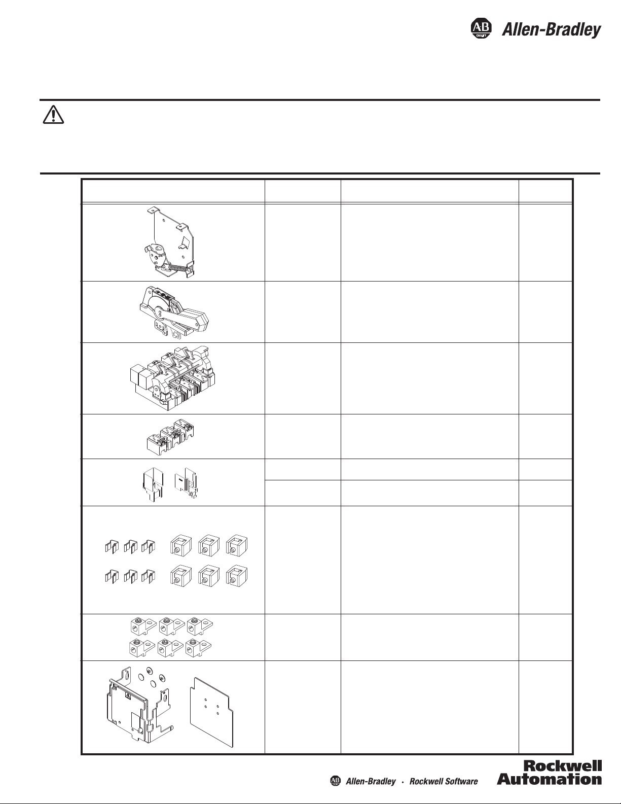
Disconnect Kit Catalog No. Description
1494F-MS36
1494F-MS100
1494F-MS200
1494F-M1
1494F-P1
1494F-S1
1494F-D30
1494F-D60
1494F-D100
1494F-D200
1494F-FS30
1494F-FS60
1494F-FS100
1494F-FS200
1494F-PH2
30 / 60 Amp Mechanism
100 Amp Mechanism
200 Amp Mechanism
5-1/2" Painted Metal Handle
5-1/2" Molded Handle
5-1/2" Stainless Steel Handle
30 Amp Switch
60 Amp Switch
100 Amp Switch
200 Amp Switch
30 Amp Fuse Block
60 Amp Fuse Block
100 Amp Fuse Block
200 Amp Fuse Block
30 / 60 Amp Phase Barrier
NEMA Starter
Size(s)
0 - 2
3
4
0 - 4
0 - 4
0 - 4
0 - 1
2
3
4
0 - 1
2
3
4
0 - 2
1494F-PH3
1494F-PH4
1401-N41
1401-N42
1401-N43
1401-N44
1401-N45
1401-N50
1401-N51
1401-N52
1401-N53
1401-N54
(Included)
1494R-N1
1494R-N2
1494R-N3
1495-N50
1495-N51
1495-N56
1495-N57
100 Amp Phase Barrier
200 Amp Phase Barrier
Fuse Clip, Class H, 30A - 250V
Fuse Clip, Class H,J, 30A - 600V,
Class H, 60A-250V
Fuse Clip, Class H,J, 60A - 600V
Fuse Clip, Class H,J, 100A-250V, 100A-600V
Fuse Clip, Class H,J, 200A-250V, 200A-600V
Fuse Clip, Class R, 30A - 250V
Fuse Clip, Class R, 30A - 600V, 60A-250V
Fuse Clip, Class R, 60A - 600V
Fuse Clip, Class R, 100A - 250V, 100A-600V
Fuse Clip, Class R, 200A-250V, 200A-600V
Lug Connector: Wire Size #14 . . . #8 AWG
Lug Connector: Wire Size #14 . . . #4 AWG
Lug Connector: Wire Size #14 . . . #1/0 AWG
Lug Connector: Wire Size #6 . . . #4/0 AWG
Fuse Cover
Fuse Cover
Fuse Cover with Door
Fuse Cover with Door
3
4
0 - 2
0 - 3
0 - 3
3-4
3-4
0 - 2
0 - 2
0 - 2
3-4
3-4
0-1
2
3
4
0 - 3
4
0 - 3
4
Page 2
Bulletin 1494F Disconnect Switch and Accessory Kits
2
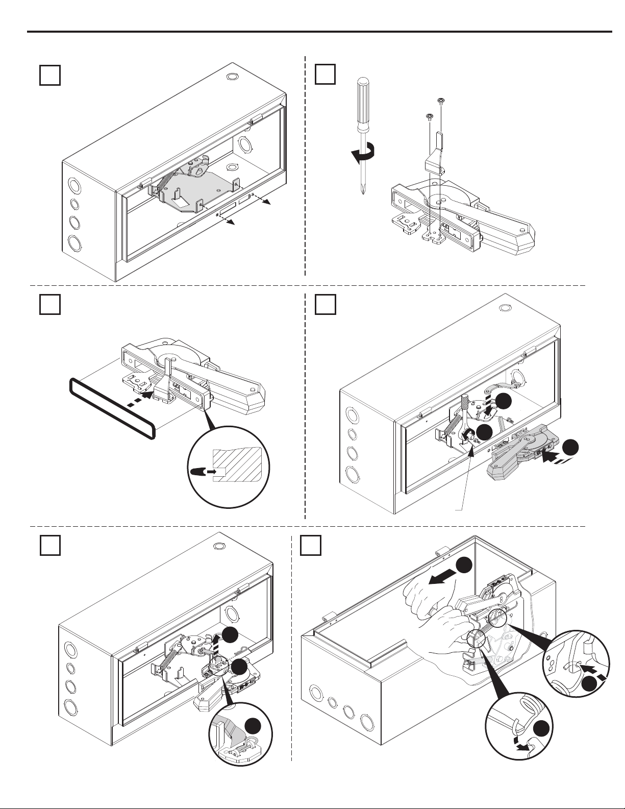
Operating Mechanism and Handle Installation
1
2
7-11 lb-in
43
3
2
1
23-37 lb-in
65
2
1
2
1
3
Publication 1494F-IN012D-EN-E - January 2013 42052-042-01 DIR 42052-042 (Version 04)
3
Page 3
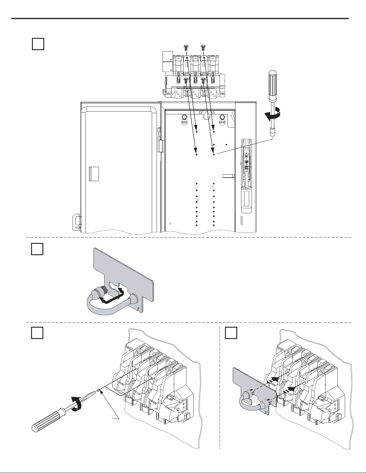
Disconnect Switch Installation
1
Bulletin 1494F Disconnect Switch and Accessory Kits
22 - 37 lb-in (30A - 100A)
40 - 60 lb-in (200A)
3
2
LINE TERMI
NAL GUARD
3 4
IF PRESENT
DISCARD (2)
THREAD-FORM
SCREWS
LINE TERMINAL GUARD
Publication 1494F-IN012D-EN-E - January 2013 42052-042-01 DIR 42052-042 (Version 04)
Page 4

Bulletin 1494F Disconnect Switch and Accessory Kits
4
Trailer Fuse Block Installation
Note: Not required for non-fusible disconnect switch applications.
1. Refer to the gures and chart below to determine the position on the mounting plate and the orientation of
the trailer fuse block.
Orientation "A"
(Bottom Holes)
Orientation "B"
Position 1
Position 2
Position 3
Position 4
Position 5
Position 6
Position 7
Position 8
Position 9
(Bottom Holes)
30/60 Amp Disconnect Switch
and Trailer Fuse Block on a
NEMA Size 0…2 Combination Starter
Voltage
Position
1
6
1
3
3
7
2
3
4
Orientation
Amps
B
A
B
B
A
A
A
B
B
30
30
30
30
60
60
60
60
100
250
600
600
600
250
600
600
600
600
Fuse Class
H/R
H/R
J
HRCII-C
H/R
H/R
J
HRCII-C
J
Position
100 Amp Disconnect Switch
and Trailer Fuse Block on a
NEMA Size 3 Combination Starter
Voltage
60
60
60
60
2
1
6
3
6
8
4
7
5
Orientation
B
B
A
A
A
B
A
A
A
Amps
100
100
100
100
200
250
600
600
600
250
600
600
600
600
2. Tighten the (2) screws to 23 - 37 lb-in (30A - 100A) or 40 - 60 lb-in (200A)
Fuse Class
H/R
J
H/R
HRCII-C
H/R
H/R
J
HRCII-C
J
200 Amp Disconnect Switch
and Trailer Fuse Block on a
NEMA Size 4 Combination Starter
Position
3
6
1
1
5
7
2
2
Amps
100
100
100
100
200
200
200
200
Voltage
250
600
600
600
250
600
600
600
Fuse Class
HRCII-C
HRCII-C
H/R
H/R
J
H/R
H/R
J
Publication 1494F-IN012D-EN-E - January 2013 42052-042-01 DIR 42052-042 (Version 04)
Page 5

Bulletin 1494F Disconnect Switch and Accessory Kits
Phase Barrier and Fuse Clip Installation (Switch Rating 30, 60 Amp)
Determine which part attaches to the disconnect by referring to the table below and the part number that is
imprinted on the side of the phase barrier:
Amp
Rating
30/60
100
200
Phase Barrier
Catalog Number
1494F-PH2
1494F-PH3
1494F-PH4
Part Number
(Attached to Disconnect)
40392-097
40392-099
Part Number
(Attached to Fuse Block)
40392-098
40392-100
1 2
5
1
Click
1
2
Click
2
43
22 - 37 lb-in
2
1
Publication 1494F-IN012D-EN-E - January 2013 42052-042-01 DIR 42052-042 (Version 04)
Page 6

Bulletin 1494F Disconnect Switch and Accessory Kits
6
Phase Barrier and Fuse Clip Installation (Switch Rating 100 Amp)
1
Switch Phase Barrier
Fuse Clip Size and Class
60 A
100 A
200 A
200 A
600V H - R
600V H - R
600V H - R
250V H - R
Trailer Block Phase Barrier
2
2
1
1
Fuse Clip Size and Class
60 A
60 A
100 A
100 A
250V H - R
600V J
250V H - R
600V J
600V J200 A
32
1
Click
2
1
2
Click
16 - 22 lb-in
2
54
1
1
Publication 1494F-IN012D-EN-E - January 2013 42052-042-01 DIR 42052-042 (Version 04)
2
22 - 37 lb-in
Page 7

Bulletin 1494F Disconnect Switch and Accessory Kits
Phase Barrier and Fuse Clip Installation (Switch Rating 200 Amp)
1
7
4
16 - 22 lb-in
2
Click
1
2
3
1
2
Click
3
3 4
Publication 1494F-IN012D-EN-E - January 2013 42052-042-01 DIR 42052-042 (Version 04)
16 - 22 lb-in
22 - 37 lb-in
Page 8

Fuse Cover Installation
Size 0 - 3
30 A, 60 A, 100 A Non-Fused
30 A, 250 V, Class H, R Fuses
30 A, 600 V, Class H, R Fuses
60 A, 250 V, Class H, R Fuses
60 A, 600 V, Class H, R Fuses
200 A, 600 V, Class H, R Fuses
100 A, 600 V, Class H, R Fuses
100 A, 250 V, Class H, R Fuses
200 A, 250 V, Class H, R Fuses
200 A, 600 V, Class J Fuses
2
3
1
2
3
Size 4
Cat 1495-N58
Non-Fused
200 A, 250 V, Class H, R Fuses
200 A, 600 V, Class H, J, R Fuses
1
Click
1
2
1
Click
Testing of Disconnect Switch
1. Verify that both the disconnect switch and the disconnect handle are in the OFF position. (the disconnect switch can be moved into the OFF position by moving the crossbar downward so that the blades are exposed)
2. To test that the disconnect switch and the mechanism are properly aligned. Verify that the disconnect switch can be turned on by moving the defeater lever downward and moving the disconnect handle to
the ON position (the blades should enter the disconnect switch arc hood).
3. Verify that the disconnect switch can be turned o by moving the disconnect handle to the OFF position (the blades should exit the disconnect switch arc hood).
Allen-Bradley, Rockwell Software, and Rockwell Automation are trademarks of Rockwell Automation, Inc.
Trademarks not belonging to Rockwell Automation are property of their respective companies.
Publication 1494F-IN012D-EN-E - January 2013
Copyright © 2013 Rockwell Automation, Inc. All Rights Reserved. Printed in USA.
DIR 42052-042 (Version 04)
42052-042-01
 Loading...