

Page 1
69
BULLETIN
INSTRUCTIONS 1494D
I
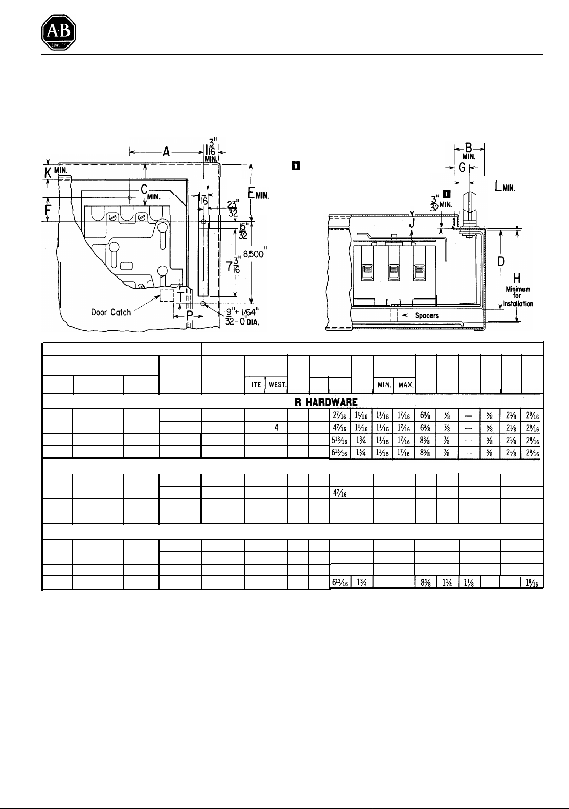
FLANGE MOUNTED CIRCUIT BREAKER OPERATORS
FOR 100, 225 AND 400 AMPERE FRAMES
ENCL
OSURE CONSTRUCTION
k---A--dL
I ’
Ii
7 ’
5I 23
:
0 3/32" minimum
T
I
37
the door to clear the flange
plate. A smaller dimension increases “G” and “B” by 3/1 6”
minimum and “L” by 3/8" min.
is required
for
-
LMIN.
L
Enclosure Flange
#10 Gauge Max.
Circuit Breaker
Frame Size
AmperesWestinghouse ITE
Maximum
Current A
Rating
(Amperes)
ITE WEST.
B
C
WITHOUT DOO
5
4
100 EB, EHB, FB E, EF, EH 70
225
JA, KA FJ
400 LB,LBB, HLB
-
150 4
225 3
400 3
/16 21/4 2 2 415/16 21/2
5
1
/
/16 2
/4 4
1
1
/8
2
/4 5 5 615/16 5
7
/8 21/4
-
6 6
SMALL & INTERMEDIATE ENCLOSURES WITH DOOR HARDWARE
100 EB,EHB,FB E,EF,EH
225
JA, KA FJ
400
LB,LBB,HLB
-
70
150
225
400
5
4
/16 29/16 2 2 415/16 21/2 21/16 11/16 13/8
5
4
/16 29/16 4 4 415/16 41/2 d7/16 11/16 13/8 63/8 7/8
7
3
9
3
/8
2
/16 5 5 615/165
7
/8 29/16
-
LARGE ENCLOSURES WITH DOOR HARDWARE
100
EB, EHB, FB E,EF, EH
225 JA, KA FJ 225
400 LB,LBB,HLB
- 400
70 4
150 4
5
/16 29/16 21/4 25/16 415/16 23/4
5
9
4 4
2
/16
/16
7
3
/8 29/16 5 5 613/165
7
3
/8 29/16
-
INSTRUCTIONS
NOTE: The circuit breakers are not supplied with these
kits and are shown only for convenience.
1. Select the table which applies to your enclosure.
2. Determine the enclosure flange width “B” and the
mounting depth “H” to ensure the cabinet is at least as
large as these minimum values.
3. Refer to N.E.C. for required wire bending space, Di-
mension “C”. The minimum value given for “C” is the
minimum wire bending space for the maximum wire
size that can be connected to each circuit breaker for
its current rating.
Dimensions in Inches
E G
D
F H J K L P T
15
4
/16 41/2
13
/16
15
/16
-
13
6 6
6 6
13
/16 5
15
/16
15
4
/16
15
/16
13
-
6
3
2
7
1
4
4
/2
13
13
/16
5
-
1
/16 13/4
/16 13/4
/4 11/16 13/8 63/8 11/4 11/8 5/8 21/4 19/16
/16 11/16
3
/16
1
/4
4. Provide slot and mounting holes on the right hand
flange as indicated.
5. Provide spacer brackets for the circuit breaker mount-
ing plate as shown. Typical spacer brackets are shown
on Page 2. Please note notch and clearance holes required for slide assembly.
6. Locate door catch using
enclosures using door hardware disregard the door
catch supplied with operating mechanism. Instead, use
door catch furnished with door hardware, and refer to
Page 4 for additional door catch instructions.
3
6
/8 7/8 11/16
3
7
7
/8
/8
/8
6
3
1
/8 67/8 7/8 11/16 5/8 21/8
3
1
/8 63/8 11/4 11/8
3
1
/8 83/8 11/4 11/8 5/8 2
3
1
/8
"P"
and “T”. NOTE: With
5
11
/8 25/32 21/8
/16 5/8 25/32 21/8
11
/16 5/8 25/32 21/8
5
/8 21/4
1
/4
5
/8 21/4
2
1
1
1
9
/16
9
/16
9
/16
1%6
Publication 1494D-5.0-December 1975
1494D-800Supersedes Instructions
41494D-80
Dated June, 1970
Page 2
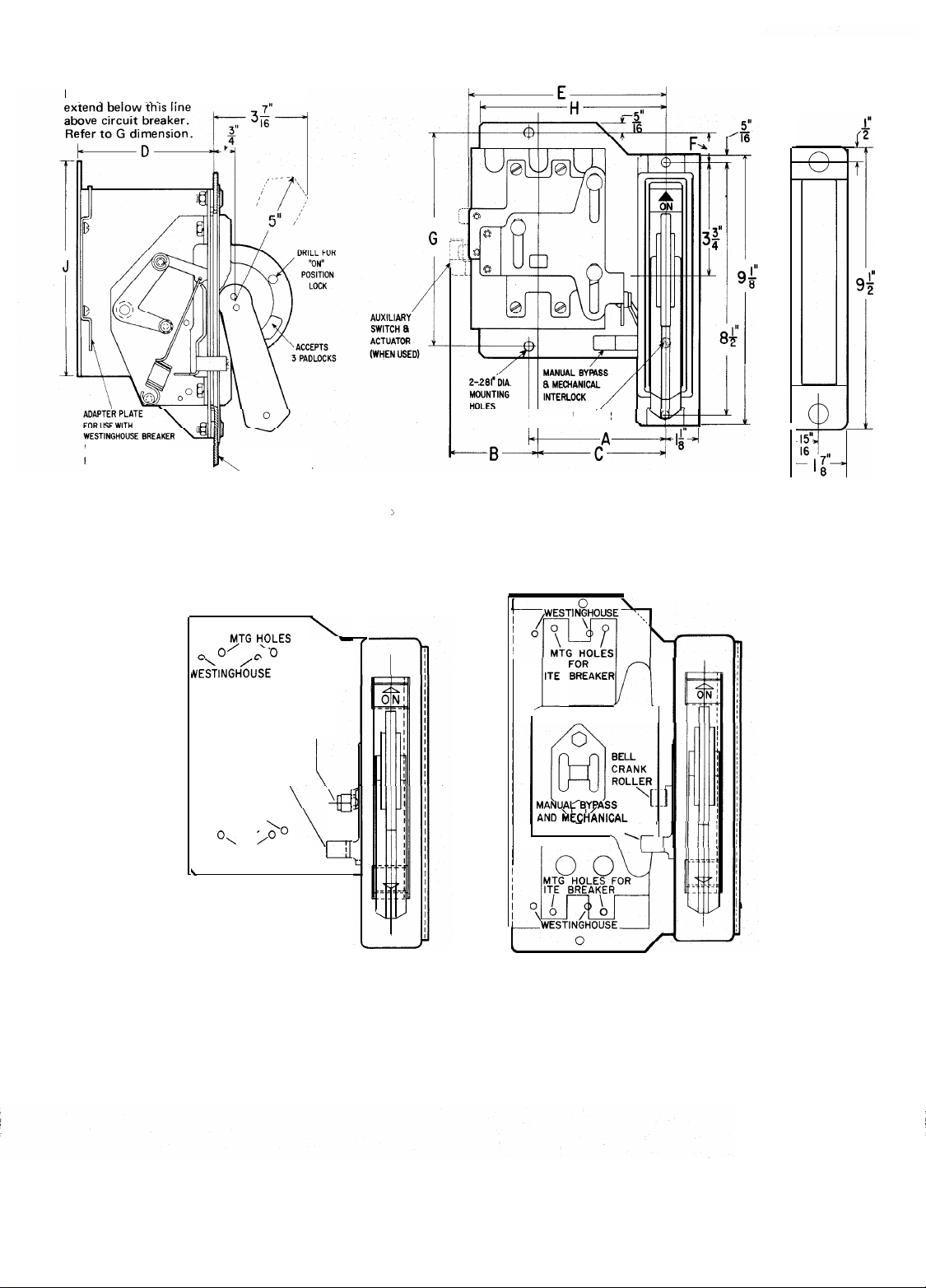
Metal Darts must not
extend below this line
;;pFs3;J
WITH AN EB, EHB OR FB
FRAME ONLY
ENCLOSURE FLANGE
10 GAUGE MAX
OPERATOR AND SLIDE MECHANISM
DEFEATER
I I
100A Frame Size Shown
FLANGE PLATE
0
ITE YTG
o”
NE&NGH<“SE
NESTINGHOUSE
0’
ITE MTG HOLES
\
H\OLES
o”
MTG
HOLES
MANUAL BYPASS
AND MECHANICAL
INTERLOCK
MTG
HOLES
O\ /O
\
‘0
0
BELL
CRANK
ROLLER
100A Frame Size
CIRCUIT BREAKER MOUNTING
.
JITE “‘AKEF~,/J
\
-El
INTERLOCK
I
225A and 400A Frame Size
\‘I-
-2-
Page 3

DIMENSIONS
Circuit Breaker
I
Frame Size
Amperes Westinghouse
100
225
400
EB,EHB,FB E,EF,EH 4
JA, KA
LB,LBB, HLB
B
ITE
FJ
A
ITE WEST ITE WEST
-
5
/16 35/16 31/4
7
-
/8
-
1 1
INSTALLATION INSTRUCTIONS
Operating Mechanism
NOTE: For ease of assembly it might be advisable to
install the circuit breaker operator and then the circuit
breaker.
1. Remove nuts and washers from flange plate.
2. Place the operating mechanism into the enclosure with
the operating handle in the ‘Off’ position. Tilt the
assembly under the flange and at the same time bring
the handle through the slot provided.
3. Place flange plate studs through the holes in the flange
and mechanism frame while holding the assembly
against the under side of flange. Secure assembly to
flange.
4. Attach operating mechanism mounting bracket firmly
to the enclosure mounting plate surface. See line
drawing Page 1 (Bolts and spacers are furnished by
user).
NOTE: It is recognized that holes in the enclosure
mounting plate surface used to secure the circuit breaker
operating mechanism can be located previous to installation. Refer to line drawings on Page 2.
Circuit Breaker Operator Mechanism
1. Place the circuit breaker Operating Mechanism handle
in the “ON” position by first pushing the defeater
by-pass lever upward and then moving the operator
handle from “OFF” to “ON”.
2. Place circuit breaker toggle lever in the “ON”
position.
3. Place circuit breaker Slide Mechanism on top of
breaker so that the slide bushings seat in the breaker
mounting holes, the toggle lever is through the slide
slot and the slot for receiving the bellcrank roller is
oriented
circuit breaker terminals, as illustrated on Page 2.
and Slide Mechanism
90” clockwise from the line side of the
- -
-
Dimensions in Inches
C
1
4
/4 41/8 415/16
7
-3
(
3
/8 43/835413435/85/1615/16 145/8
D F G H J
ITE
NOTE: Loosen adjustment plate screws on slide
mechanism, when provided.
4.
Insert the long mounting screws into the circuit
breaker mounting holes.
WESTINGHOUSE BREAKER WITH EB, EHB, or
5.
FB FRAME ONLY. Secure adapter plate provided
with Slide Mechanism Kit, onto the mounting
bracket, as illustrated on Page 2.
6.
Position circuit breaker assembly obtained in steps 3
and 4 so that the breaker line terminals are toward
the “ON” direction of the Operating Mechanism
handle and the bellcrank roller (operating mechanism) is in the bellcrank slot (slide mechanism).
Align the four circuit breaker mounting screws with
7.
the proper tapped holes in the Operating Mechanism
frame mounting surface. See illustrations on Page 2
for ITE and Westinghouse mounting.
8.
CAUTION: Position circuit breaker so that mounting
screws are perpendicular to mounting surface and
secure the breaker to Operating Mechanism frame by
tightening the mounting screws.
NOTE: The circuit breaker can be secured onto the
Operator Mechanism mounting frame either before or
after the Operator Mechanism has been secured to the
enclosure flange.
ITE BREAKER WITH FJ FRAME AND WESTING-
9.
HOUSE BREAKER WITH JA FRAME ONLY. Ad-
just the drive plate on the slide, per instructions
provided on Slide Mechanism.
10.
Move Operator Mechanism handle from “ON” to
“OFF” and then from “OFF” to “ON” to ensure
proper mechanical and electrical operation.
CAUTION: Place Operator Mechanism handle in
11.
“OFF” position before installation of wiring, for
maximum safety.
E
WEST.
9
6
/16 63/8 11/16 73/16
7
1 1 1 1 1
3
1
/4
10
1
6
/4
7
/8 6 11
I
13
7
/16
1
/2
1
-3-
Page 4

B-jp
DOOR AND HARDWARE CONSTRUCTION
il
//j
‘I
I
Small and intermediate
1
Enclosures
I
Lat.
Nos.1494F-L1
i:
A!-
Large Enclosures
(Cat. No. 1494F-L4
Hardware Kit)
M
il
-++B
~-------_-_-____
-------------
Frame Size
Amperes
225
W ‘estlnghouse 1 ITE
I
I
225
0:
I
JA, KA
Use with Hardware Kits 1494F-L1 (to
for 1494F-L2);
iij
‘1
I
%
Circuit Breaker
Maximum
I
Current
Rating
[ (Amperes)
LARGE ENCLOSURES
225 4
p
side
d
I
150 4
400 4
latching); 1494F-L2 (top and bottom latching); and 1494F-L3 (side latching accessory
Min.
Clearance
for 2 - #1/4-20
Holes
Dimensions in Inches
A B C D
E
ITE WEST.
Q
11
1
3
2 3 /16 3/8
1
/2 311/16 31/8 163/16 163/16 5/8 5/16 21/4 19/16
1
/2 311/16 31/8
1
3
-
13
14
1
7
17
/8 131/
/8
14
Hardware Dimensions
Kits in Inches
Catalog No. K M
1494F-L1
1494F-L2
1494F-L4
F G
5
/8 5/16
8
13
/16 5/8 5/16 21/4 19/16
3
/16
5
/8 5/16 21/4 19/16
q Use with Hardware Kit 1494F-L4 (top, side and bottom latching).
3
-
-
Min.
1
/4
-
5
6
P T
25/32
1
2
/4 19/16
2%
I
GUIDELINES
Small Enclosures: 30” high or less with 2 or 3 point latch-
ing. Intermediate Enclosures: 30” thru 48” high with 3
point latching. Large Enclosures: Above 48” high with 3
point latching.
INSTRUCTIONS
1.
Check all minimum enclosure and door dimensions
required for installation. Refer to Page 1 and above.
2. Select the dimensions from above which apply to the
roller latching arrangement to be installed.
NOTE: Door catch supplied with operating mechanism
is not to be used with these door hardware kits.
3. Locate holes in door to secure handle assembly.
4. Determine Dimensions “B” and “C” to locate locking
bar guide bracket(s).
5. Locate door catch using “P” and “T” dimensions. Location varies with each hardware kit. On 1494F-L4
hardware kits, attach the adjustable catch after the
support bracket is located. NOTE: Door catch and
guide bracket(s) are made with projections for welding
to the enclosure door. However, if a specific installation permits, holes can be drilled in the door catch and
guide bracket(s) using the projections as centers. Then,
after proper location and using them as templates,
corresponding holes can be drilled in the enclosure
door. Door catch and guide bracket(s) are then fastened to the enclosure door with hardware furnished
by user.
6. Establish the length of the top locking bar by meas-
uring Dimensions “E” and subtracting 3/4" for Kits L1
and L2; subtract 1-1/8" for Kit L4. Determine the
l
ength of the bottom locking bar by measuring Dimen-
sion “K” and subtracting 3/4" for Kit L2; subtract
l-l/8" for Kit L4. Dimension “H” is determined by
measuring Dimension “D” and adding 3-3/4" for Kits
L1 and L2; add 3-5/8" for Kit L4. Locate, drill, and
tap holes where necessary. NOTE: These standard mill
rectangular locking bars are not supplied with these
kits.
7. The door locking hardware assembly can now be attached to the door.
Page 5

INSTALLATION OF DOOR HARDWARE KITS
Enclosure
Size
Small
and
Intermediate
Large
Hardware
Kits
Catalog No.
1494F-L1
1494F-L2
1494F-L3
1494F-L4
INSTRUCTIONS
Locking Bar(s) and Handle Assembly
Using the roller latching arrangement to be installed and
the locking bar(s) prepared as specified on Page 4 proceed
as follows:
1.
Insert cam bearing(s) into the cam plate hole(s), insert
locking bar(s) in the cam bearing slot(s) and secure b
using the pin(s) provided. See above. NOTE: An alternate method requires using the screw(s) and nut(s) also
provided.
2. Remove door handle and cover plate from the handle
assembly.
removed from assembly
3. Slide locking bar(s) attached to the cam assembly
through the slot in the guide bracket(s) located on the
enclosure door.
NOTE: Rubber sealing gasket should not be
.
Dimensions
A
1
1%
Degrees
in Inches
B C
4
6
65
75
y
4. Insert cover plate studs through holes in door and
secure to cam assembly
5. Replace handle.
NOTE: An alternate method of assembly requires that the
.
handle assembly beinstalled first and then attach locking
bar(s) to the cam plate.
Roller Assembly and Defeater Actuator Lever
Attach top roller assembly and bottom roller assembly
(when used) to the locking bar(s). A slotted hole on
roller assembly provides adjustment to insure proper
gasket sealing when enclosure dimensional variation
are encountered.
Fasten side roller assembly (when used) to the cam
plate using various shims supplied. Nominal enclosure
dimensions will require one (1) 1/8" shim
Attach the defeater actuator lever to the upper locking
bar. Refer to inset for assembled view as seen from
inside of enclosure. The two screws should be located
near the center of the adjustment slot. Refer to Dimension “A”. Further adjustment may be required after
disconnect switch is installed
.
.
Door Hardware Adjustments
With the operating handle mechanism secured to the
flange in the “Off” position and the door hardware attached to the door proceed as follows:
1.
Close enclosure door and slowly turn the handle to the
right (counterclockwise) until the first notch on the
cam plate is engaged. At this point positive gasket seal
should be obtained with proper roller adjustment.
When seal is obtained further adjustment to the defeater actuator lever may be required if the operator
mechanism handle can be moved to the “On” position.
Rotate door handle further to the right. Relocate
2.
defeater actuator lever if necessary, so that the operating handle mechanism “On” position occurs well
before the fully latched (vertical) door handle position.
3.
With the operating handle in the “Off” position, turn
recessed door defeater screw, hold and simultaneously
turn handle to the left and pull. Door should open.
Close door, turn door handle to fully latched position
.
4
and place disconnect switch in “On” position. Turn
recessed door defeater screw, hold and at the same
time turn door handle to the left and pull. Door should
open only partially. Maintain force on handle and turn
recessed defeater
should now open.
Close door and rotate door handle to the fully closed
5.
position. Pull out handle padlocking bar. Insertion of a
3/16" minimum to 3/8" maximum lock hasp should
prevent against movement of the door handle.
screw
in cabinet flange. The door
s
ALLEN-BRADLEY
Milwaukee, Wisconsin 53204
w
0
 Loading...