

Page 1

Bulletin 1494C Cable Operated Disconnect Switch Kit (30A - 200A)
Installation Instructions
(Cat 1494C- _ _ _ Series 2 : 30A, 60A, 100A and 200A)
WARNING
WARNING
To prevent electrical shock, disconnect from power source before installing or servicing. Follow
NFPA 70E requirements. Install in suitable enclosure. Keep free from contaminants.
The following procedures are critical to the proper operation of the disconnect handle and switch.
Failure to follow these steps can result in damage to the equipment and/or serious injury or death to the
operator.
Table of Contents Page
Quick Installation Guide
- Disconnect Switch Installation 2,3
- Disconnect Handle Installation 3
- Assemble and Install Line Terminal Guard 4
- Cable Mechanism Installation 4
- Connecting Rod Adjustment Procedure 5
Enclosure Without Handle Cutout 6
- Locate Handle
- Drill Handle Holes
Door Catch Mounting Bracket Installation 7
Trailer Fuse Block Installation (30A, 60A, 100A) 8
Trailer Fuse Block Installation (200A) 9
Fuse Clip Installation and Phase Barrier Replacement (30A, 60A) 10
Fuse Clip Installation and Phase Barrier Replacement (100A) 11
Fuse Clip Installation (200A)
12
Fuse Clip Installation (Switch Rating 200A) for 400A Class J Fuses 13
Phase Barrier Replacement (200A) 14
Bulletin 1494C Cable Operated Disconnect Switch Kit Components 15
Bulletin 1494C Cable Operated Disconnect Switch Kit Optional Accessory List
16
42052-123-01 (3)
Printed in U.S.A.
Page 2
QUICK INSTALLATION GUIDE
NOTICE
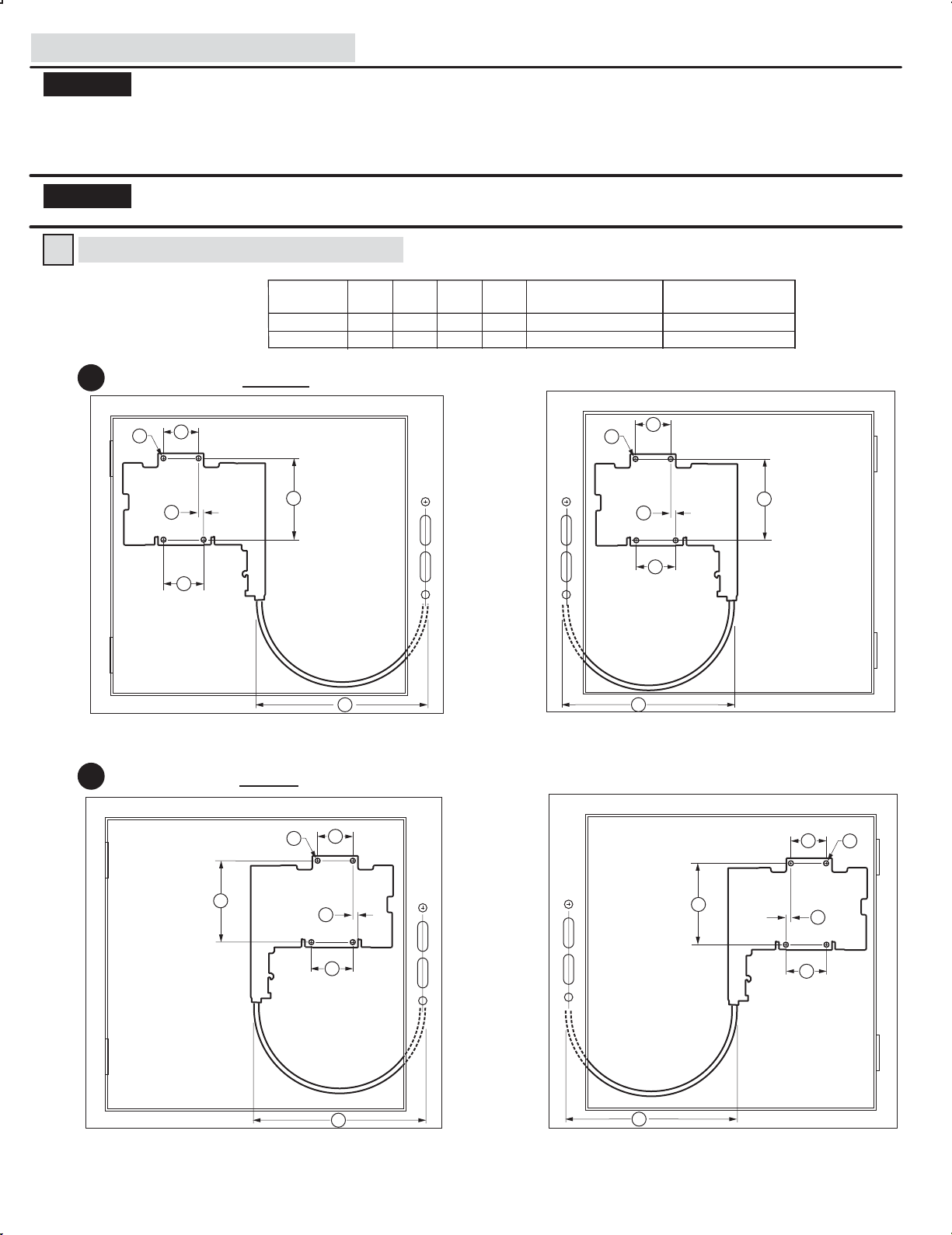
When locating the 30A, 60A and 100A switch, verify that the minimum diameter for the loop of the cable between the switch
mechanism and handle mechanism is not less than 12 inches.
When locating the 200A switch, verify that the minimum diameter for the loop of the cable between the switch mechanism and
handle mechanism is not less than 16 inches.
Any reduction to the diameter of the bend loop for the cable will reduce the efficiency of the cable system, and create additional drag
and friction within the cable conduit.
NOTICE
Disconnect Switch Installation
1
1a
Verify that the cable assembly does not interfere with any mechanical and moving parts. Keep the cable conduit a minimum of 1/2"
from all heat sources and current carrying terminals, fuses, transformers, etc.
Switch
Size
30A, 60A, 100A
200A
Locate switch with right hand mechanism
AA
EE
DD
BB
Panel Mounting Dimensions
AA BB CC DD
2-1/4" 5-1/4" 2-1/4" ----
2" 8-1/4" 4-1/4" 1-1/8"
EE
11/64" Dia.
7/32" Dia.
EE
DD
(4) Mounting Plate Holes
Minimum Bend Diameter
FF
12" Dia.
16" Dia.
AA
BB
CC
Enclosure with Right Hand Flange
Locate switch with left hand mechanism
1b
EE
BB
CC
FF
FF
Enclosure with Left Hand Flange
AA
DD
CC
BB
EE
AA
DD
CC
FF
FF
Enclosure with Right Hand Flange Enclosure with Left Hand Flange
(2)
Page 3
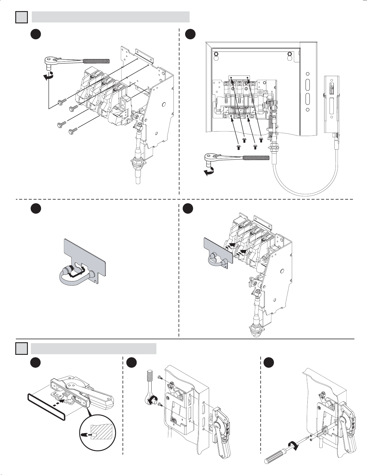
Disconnect Switch Installation (Cont'd)
1
Assemble disconnect switch to cable switch
2
mechanism
23 - 37 lb-in (30A - 100A)
40 - 60 lb-in (200A)
Thread forming
screws
provided with
disconnect switch.
Disconnect Switch with
Right Hand Cable Mechanism
(shown)
Assemble disconnect switch assembly to mounting plate
3
23 - 37 lb-in
(30A - 100A)
40 - 60 lb-in
(200A)
Thread forming
screws
provided with cable
mechanism.
Install rubber handle on line terminal guard Install the line terminal guard on disconnect switch
4
LINE TERMIN
AL GUA
RD
Disconnect Handle Installation
2
Install gasket
1 2 3
Install handle and mechanism bracket
5
LINE TERMINAL GUA
RD
Install defeater lever
30-40 lb-in
(Right Hand
Flange Mounted
Shown)
7-11 lb-in
(3)
Page 4
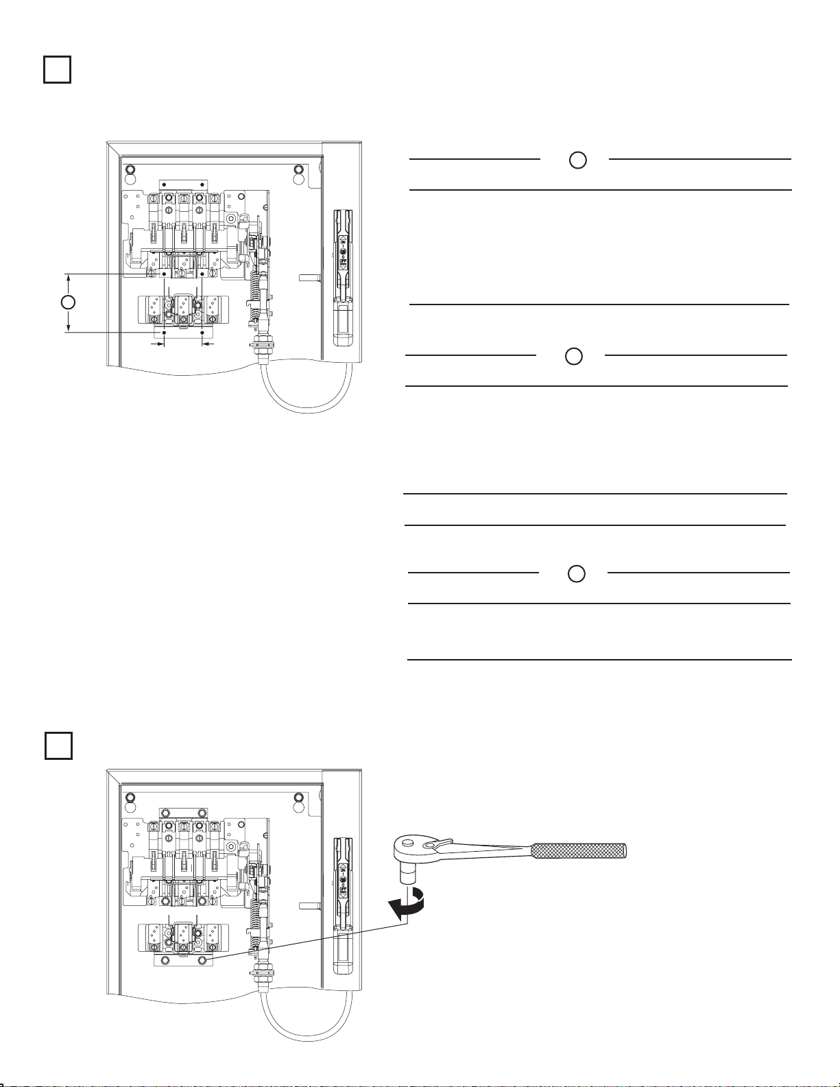
Cable Mechanism Installation
3
Verify that disconnect switch and handle are in "ON" position.
1
(Switch blades will not be visible)
Rotate connecting rod (clockwise) into drive bar until it
2
bottoms out
Rotate connecting rod (counter-clockwise):
3
30A - 60A - 100A (1) full turn
200A (3) full turns
Align connecting rod with primary link
4
Connecting
Rod
Primary Link
(4)
Page 5
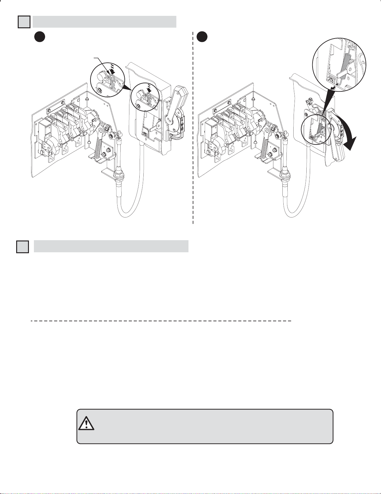
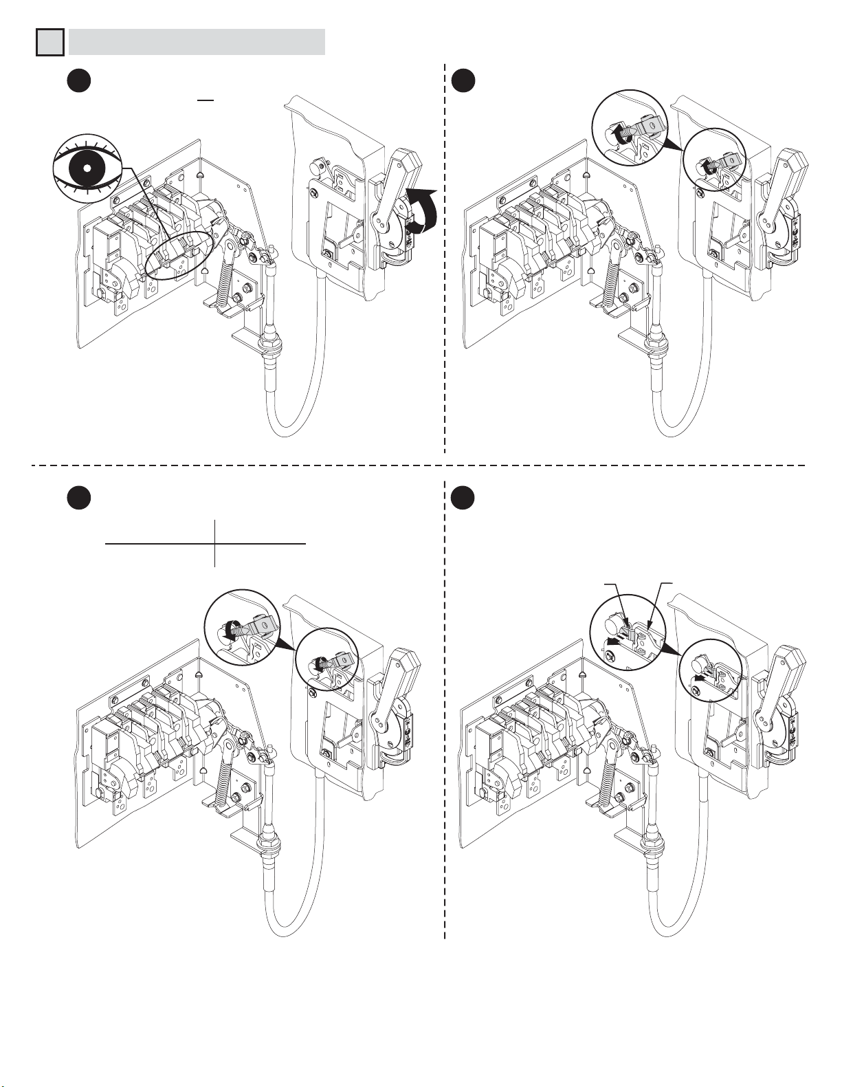
Cable Mechanism Installation (Cont'd)
3
Install hitch pin clip Turn disconnect handle "OFF" and
5 6
Hitch Pin Clip
install handle mechanism spring
Connecting Rod Adjustment Procedure
4
"ON" Position
Move disconnect handle to the "ON" position.
➊
If switch does not fully close, return handle to "OFF" position.
➋
Remove link spring hitch pin and disengage the connecting rod from the primary link.
➌
Turn connecting rod counter-clockwise (1 or more) full turns.
➍
Re-engage connecting rod in primary link of handle, insert hitch pin and re-test
➎
Repeat ➊ -
➏
Re-install link spring.
➐
"OFF" Position
Move disconnect handle to the "OFF" position.
➊
If switch does not fully open, return handle to "ON" position.
➋
Remove hitch pin and link spring, then disengage the connecting rod from the primary link.
➌
Turn connecting rod clockwise (1 or more) full turns.
➍
Re-engage connecting rod in primary link of handle, insert hitch pin and re-test.
➎
Repeat ➊ - ➎ as necessary.
➏
Re-install link spring.
➐
as necessary.
➎
ATTENTION: CHECK FOR PROPER OPERATION. Upon completion of
the installation instructions, no further adjustment of the cable mechanism is
required.
(5)
Page 6

Enclosure without Handle Cutout
● Enclosures with a Flange Thickness less than 3/16" use dimensions below to install disconnect handle.
● Enclosures with a Flange Thickness 3/16" and greater use dimensions in alternate Mounting Kit 1494V-H3 to install disconnect
handle.
Locate Handle
1
Drill Handle Holes
2
C
Right Hand Flange
C
B
A
B
A
Top Handle Hole
Left Hand Flange
Top Handle Hole
To make slot drill (3) 1/2" diameter holes and remove burrs
NEMA
SIZE
30A, 60A
100A
200A
A
(min)
4 - 5/8"
6 - 1/16"
10 - 1/8"
(min)
1 - 1/8"
1 - 1/8"
1 - 1/8"
(2) .265 Dia. Holes
G
H
J
H
Enclosure Dimensions
B
C
(max)
1 - 1/16"
1 - 1/16"
1 - 1/16"
(6)
F
4 - 11/16"
4 - 11/16"
4 - 11/16"
F
G
1 - 9/16"
1 - 9/16"
1 - 9/16"
H
1"
1"
1"
J
7/8"
7/8"
7/8"
Page 7

Door Catch Bracket Installation
Right hand installation shown (for left hand installation follow similar procedures)
Door Catch Mounting Bracket:
●
Provided with projections for welding.
●
Projections can also be used as a guide for drilling holes.
●
Can be used as a template to drill corresponding holes in the enclosure door.
●
User to supply the hardware for fastening the bracket.
●
Fasteners must provide the degree of ingress protection for the environmental rating of the enclosure.
● The bracket hardware must be inaccessible to unauthorized personnel.
Dimension K (3/4" to 1")
●
When using small disconnect handle kit only (1494F-P1, -M1 or -S1), use door catch provided with handle kit.
●
When using small disconnect handle kit and small door hardware kits (1494V-L1, -LL1, -L2 or -LL2), use door catch
provided with door hardware kit.
Dimension K (1-1/8" to 1-3/8")
●
When using small disconnect handle kit only (1494F-P1, -M1 or -S1), use door catch (40492-080-02) which can be
ordered from factory.
●
When using small disconnect handle kit and large door hardware kits (1494V-L3 or -LL3), use door catch provided with
door hardware kit.
Door Catch
Mounting Bracket
Top
Enclosure Door
Door Catch
Mounting Bracket
Door Catch
NEMA
SIZE
30A, 60A
100A
200A
C
E
TOP VIEW
A
(min)
4 - 5/8"
6 - 1/16"
10 - 1/8"
B
(min)
1 - 1/8"
1 - 1/8"
1 - 1/8"
B
C
D
Enclosure Dimensions
C
(max)
1 - 1/16"
1 - 1/16"
1 - 1/16"
A
D
1 - 5/8"
1 - 5/8"
1 - 5/8"
B
E
2 - 3/8"
2 - 3/8"
2 - 3/8"
Flange
Thickness
Enclosure
F
4 - 11/16"
4 - 11/16"
4 - 11/16"
Base
G
1 - 9/16"
1 - 9/16"
1 - 9/16"
B
A
Door Catch
K
H
1"
1"
1"
J
7/8"
7/8"
7/8"
C
E
Top Handle Hole
Door Catch
Mounting
Bracket
D
D
Door Catch
Mounting
Bracket
(7)
Right Hand Flange Left Hand Flange
Page 8
Trailer Fuse Block Installation
Trailer Fuse Block Location
1
Note: Refer to the figures and chart below to determine the location on the mounting plate for the trailer fuse block.
(Not required for non-fusible disconnect switch applications.)
1494V-FS30, -FS60, -FS100
Amps Voltage Class Fuse
30
30
30
30
60
60
60
A
60
30 Amp Trailer Fuse Block (1494V-FS30)
Torque (lb-in)Fuse
Fuse
Clip
37 22-37 20-25 20-25
250
600
600
600
250
600
600
600
H/R
H/R
J
HRCII-C
H/R
H/R
J
HRCII-C
A
2-27/32"
5-5/8"
2-27/32"
4-3/16"
3-5/8"
6-1/8"
3"
4-3/16"
Block
-
23
Lug to
Terminal
Wire
into Lug
60 Amp Trailer Fuse Block (1494V-FS60)
2-1/4"
Amps Voltage Class Fuse
30
30
30
30
60
60
60
60
100
100
250
600
600
600
250
600
600
600
600
600
H/R
H/R
J
HRCII-C
H/R
H/R
J
HRCII-C
J
H/R
A
2-27/32"
5-5/8"
2-27/32"
4-3/16"
3-5/8"
6-1/8"
3"
4-3/16"
4-15/16"
8-1/8"
Block
23-37
23-37 16-22 40-60 45-50
Torque (lb-in)Fuse
Fuse
Clip
23-37 40-60 45-50
Lug to
Terminal
Wire
into Lug
Install Trailer Fuse Block
2
100 Amp Trailer Fuse Block (1494V-FS100)
Amps Voltage Class Fuse
60
60
60
60
100
100
100
100
200
250
600
600
600
250
600
600
600
600
(See Table )
H/R
J
H/R
HRCII-C
H/R
H/R
J
HRCII-C
J
A
4-3/16"
3-9/16"
6-11/16"
4-11/16"
6-11/16"
8-11/16"
5-1/2"
7-9/16"
6-1/4"
Block
23-37
23
-
Torque (lb-in)Fuse
Fuse
Clip
22-37 90-110 150-165
37 16-22 90-110 150-165
Lug to
Terminal
Wire
into Lug
(8)
Page 9

Trailer Fuse Block Installation (Switch Rating 200A)
Trailer Fuse Block Location
1
Note: Refer to the figures and chart below to determine the location on the mounting plate for the trailer fuse block.
(Not required for non-fusible disconnect switch applications.)
1494V-FS200
200 Amp Trailer Fuse Block (1494V-FS200)
Amps Voltage Class Fuse
100
100
100
100
200
200
200
200
B
400
250
600
600
600
250
600
600
600
600
H/R
H/R
J
HRCII-C
H/R
H/R
J
HRCII-C
J
B
5-7/8"
7-7/8"
4-5/8"
4-5/8"
6-3/4"
9-1/4"
5-3/8"
5-3/8"
6-1/4"
Block
-
60
40
Torque (lb-in)Fuse
Fuse
Clip
Terminal
16-22
175-200 275-305
16-22
Lug to
Wire
into Lug
1 - 1/8"
Install Trailer Fuse Block
2
2"
(See Table )
(9)
Page 10

Switch Rating (30A, 60A Rating)
Fuse Clip Installation
1
2
23 - 37 lb-in
2
1
Phase Barrier Replacement Kit
1494F-PH2
NOTE: Fuse clips and lugs must be removed to add or replace phase barriers.
1 2
1
40392-098
2
40392-097
CLICK
1
CLICK
2
(10)
Page 11

Fuse Clip Installation (Switch Rating 100 Amp)
1
Phase Barrier Replacement Kit
1494F-PH3
NOTE: Fuse clips and lugs must be removed to add or replace phase barriers.
Switch Phase Barrier
1
16 - 22 lb-in
1
2
2
Fuse Clip Size and Class
60 A
100 A
200 A
200 A
600V H - R
600V H - R
600V H - R
250V H - R
1
Trailer Block Phase Barrier
2
23 - 37 lb-in
2
2
2
1
1
Fuse Clip Size and Class
60 A
60 A
100 A
100 A
250V H - R
600V J
250V H - R
600V J
600V J200 A
3
1
CLICK
2
1
2
CLICK
(11)
Page 12

Fuse Clip Installation (Switch Rating 200A)
Switch with Right Hand Mechanism
1
16 - 22 lb-in
2
Switch with Left Hand Mechanism
1
16 - 22 lb-in
2
1
1
Switch with Right Hand Mechanism
2
1
23 - 37 lb-in
2
Switch with Left Hand Mechanism
2
23 - 37 lb-in
1
2
(12)
Page 13

Fuse Clip Installation (Switch Rating 200A) for 400A Class J Fuses (Cat. No. 1401-N171)
NOTICE
Switch with Right Hand Mechanism
1 1
Use of 400A fuses will void the UL listing of this product.
16 - 22 lb-in
2
1
Switch with Left Hand Mechanism
16 - 22 lb-in
2
1
Switch with Right Hand Mechanism
2 2
150 - 200 lb-in
Switch with Left Hand Mechanism
(13)
150 - 200 lb-in
Page 14

Phase Barrier Replacement Kit (Switch Rating 200A)
1494F-PH4
NOTE: Fuse clips and lugs must be removed to add or replace phase barriers.
1
1
4
40 - 60 lb-in
2
CLICK
2
3
1
2
3
CLICK
(14)
Page 15

Bulletin 1494C Cable Operated Disconnect Switch Kit Components
Disconnect Switch Kit
Handle
Switch
Cable
Mechanism
Cat No.
1494F-M1 (5-1/2" Painted Metal) (30A - 200A)
1494F-P1 (5-1/2" Molded) (30A - 200A)
1494F-S1 (5-1/2" Stainless Steel) (30A - 200A)
Switch for Right Hand Mechanism
1494F-D30 (30A)
1494F-D60 (60A)
1494F-D100 (100A)
1494F-D200 (200A)
Switch for Left Hand Mechanism
1494F-DX30 (30A)
1494F-DX60 (60A)
1494F-DX100 (100A)
1494F-DX200 (200A)
Cable with Right Hand Mechanism
1494C-CM1: 30A - 100A (3 Ft Cable)
1494C-CM2: 30A - 100A (4 Ft Cable)
1494C-CM3: 30A - 100A (5 Ft Cable)
1494C-CM4: 30A - 100A (10 Ft Cable)
1494C-CM5: 200A (4 Ft Cable)
1494C-CM6: 200A (5 Ft Cable)
1494C-CM7: 200A (6 Ft Cable)
1494C-CM8: 200A (10 Ft Cable)
Cable with Left Hand Mechanism
1494C-CMX1: 30A - 100A (3 Ft Cable)
1494C-CMX2: 30A - 100A (4 Ft Cable)
1494C-CMX3: 30A - 100A (5 Ft Cable)
1494C-CMX4: 30A - 100A (10 Ft Cable)
1494C-CMX5: 200A (4 Ft Cable)
1494C-CMX6: 200A (5 Ft Cable)
1494C-CMX7: 200A (6 Ft Cable)
1494C-CMX8: 200A (10 Ft Cable)
Fuse
Block
Fuse
Clips
1494V-FS30 (30A)
1494V-FS60 (60A)
1494V-FS100 (100A)
1494V-FS200 (200A)
1401-N41 (Class H, 30A - 250V)
1401-N42 (Class H,J, 30A - 600V,
Class H, 60A-250V)
1401-N43 (Class H,J, 60A - 600V)
1401-N44 (Class H,J, 100A-250V, 100A-600V)
1401-N45 (Class H,J, 200A-250V, 200A-600V)
1401-N50 (Class R, 30A - 250V)
1401-N51 (Class R, 30A - 600V, 60A-250V)
1401-N52 (Class R, 60A - 600V)
1401-N53 (Class R, 100A - 250V, 100A-600V)
1401-N54 (Class R, 200A-250V, 200A-600V)
1401-N171 (Class J, 400A-250V / 600V)
(15)
Page 16

Bulletin 1494C Cable Operated Disconnect Switch Kit Optional Accessory List
Optional Accessories
(Installation Instructions
Not Included)
Electrical
Interlock
Switch with
Right Hand Mechanism
1495-N34 (1-N.O./N.C.) (30A - 100A)
1495-N35 (2-N.O./N.C.) (30A - 100A)
1495-N43 (1-N.O./N.C.) (200A)
1495-N44 (2-N.O./N.C.) (200A)
Switch with
Left Hand Mechanism
1495-N37 (1-N.O./N.C.) (30A - 100A)
1495-N38 (2-N.O./N.C.) (30A - 100A)
1495-N39 (1-N.O./N.C.) (200A)
1495-N40 (2-N.O./N.C.) (200A)
Cat No.
42052-123-01 (3)
Printed in U.S.A.
Auxiliary
Contact
Auxiliary
Contact
Adapter Kit
Wire Lug
Connectors
Phase
Barrier
Fuse
Cover
with Door
1495-N8 (1-N.O.) (30A - 200A)
1495-N9 (1-N.C.) (30A - 200A)
1495-N24 (30A - 100A)
(Required only for switch with
Left Hand Mechanism)
1495-N25 (200A - 400A)
(Required only for switch with
Left Hand Mechanism)
Included (30A)
(CU Wire Size #14 . . #8 AWG)
1494R-N1 (60A)
(CU Wire Size #14 . . #4 AWG)
1494R-N2 (100A)
(CU Wire Size #8 . . #1/0 AWG)
1494R-N3 (200A)
(CU Wire Size #6 . . #4/0 AWG)
1494F-PH2 (30A / 60A)
1494F-PH3 (100A)
1494F-PH4 (200A)
Switch
Rating
30A
30A
60A
30A
60A
60A
100A
30A
60A
100A
200A
200A
Fuse
Class
Non-Fusible
H, R
H, R
J
J
Non-Fusible
Non-Fusible
H, R
H, R
J
➀ Switch with right hand mechanism
➁ Switch with left hand mechanism
Fuse Clip
Rating
250V 600V
---30A
60A
30A
60A
----
----
----
----
100A
100A 100AH, R100A
200A 200AH, J, R
---- ----Non-Fusible
200A 200AH, J, R
---- ----Non-Fusible
----
----
---30A
60A
----
----
30A
60A
100A
Cat No.
1495-N64
or
1495-N56
1495-N65
or
1495-N56
1495-N66
1495-N67➀
1495-N62➁
 Loading...