

Page 1
MULTIPLE DOOR INTERLOCK
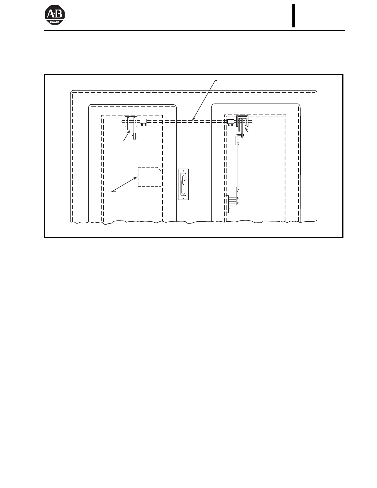
METHOD OF ASSEMBLY
Connecting Rod
Master Door
Operating
Mechanism
BULLETIN
INSTRUCTIONS 1494F
Auxiliary Door
Operating
Mechanism
Disconnect Switch
or Circuit Breaker
The multiple door interlock hardware kits are to be
used with Catalog Numbers 1494F-L4, 1494F-LL4,
1494V-L3, and 1494V-LL3 door hardware kits to provide
interlocking of Auxiliary Doors with the Master Door for
NEMA Type 1 and Type 12 enclosures.
There are two possible methods by which the Master
and Auxiliary Interlock Kit can be installed. Certain conditions dictate which method to use.
Use Assembly Method Number 1: On all normal
installations.
Use Assembly Method Number 2: Only when the connecting rod between the Master Kit and Auxiliary Kit(s)
passes over the disconnect switch or circuit breaker, as
shown in the figure above, and one of the following conditions exists:
• Dimension “E” on Page 1 of the Circuit Breaker
Operator Installation Instructions (Publication 1494D-5.0) is less than 4-3/8 in. (111) for
devices rated at 15…70 Amperes;
• Dimension “S” on Page 1 of the Flange Mounted
Disconnect Switch Installation Instructions (Publi-
Figure 1
cations 1494F-5.0, 1494M-800, and 1494M-801)
is less than 4-3/8 in. (111) for 30 and 60 Ampere
devices and less than 6 in. (152) for 100 Ampere
Devices;
• Dimension “C” on Page 1 of the Circuit Breaker
Operator Installation Instructions (Publication 1494V-5.05) is less than 5-1/2 in. (140) for
devices rated at 15…70 Amperes; or
• Dimension “C” on Page 1 of the Disconnect
Switch Installation Instructions (Publication 1494V-5.0) is less than 5-1/2 in. (140) for
30 and 60 Ampere devices.
NOTE: The purpose of Assembly Method Number 2 is to
move the connecting rod to a higher position which will
provide greater electrical clearance between it and the disconnect switch or circuit breaker.
When the method of assembly has been determined,
it is required that both the Master Kit and the Auxiliary
Kit(s) employ the same method.
NOTE: Dimensions shown in parentheses are in millimeters.
Publication 1494F-5.2 — November 2002
Supersedes Instructions 1494F-5.1 — March 1977
Page 2
ENCLOSURE CONSTRUCTION
3/16" (4.8) MIN.
7/16"
(11)
C = 3-7/8"
(98.5) MIN.
D = 11"
(279) MIN.
2 Holes 9/32" (7.1) Dia.
1-3/8"
(35)
Dia.
15/16"
(24)
1-3/8" (35)
D = 11"
(279) MIN.
2-5/8"
(66.5)
2 Holes 9/32" (7.1) Dia.
5/16" (7.9)
Door Handle
Mounting Hole
.750" (19) Dia.
2 Holes 9/32" (7.1) Dia.
3/16"
(4.8)
MIN.
5/16" (7.9)
Door Handle
Mounting Hole
.750" (19) Dia.
3/8"(9.5)
MIN.
1-3/8" (35)
2-5/8"
(66.5)
Dimension “A” Minimum
Dimension A
Disconnect
Switches
30A 8-3/4 (222)
60A 8-3/4 (222)
100A 9-1/4 (244)
200A 12-1/2 (318)n
n Applies to Bulletin 1494F only.
Bulletin
1494F
and 1494V
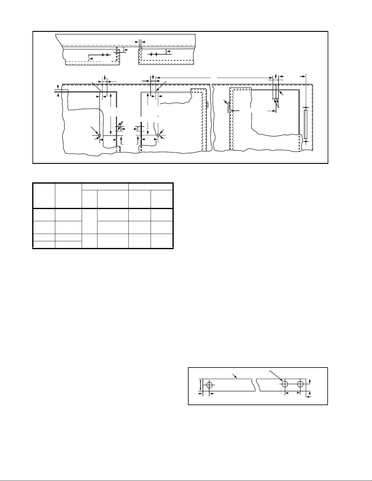
NOTE: The above figure depicts a right-hand Master
Installation. The left-hand Master Installation is a mirror
image of the right-hand installation.
A typical Master Auxiliary Installation is shown in the
figure above with one Master Kit and two Auxiliary Kits. A
maximum of 10 Auxiliary Kits can be employed with one
Master. The dimensions would simply continue. Further,
the location or position of these Kits could be arranged in
any order, so that the Master Kit could be between Auxiliary Kits or to the left of Auxiliary Kits; or the Auxiliary Kits
could be all right-hand, left-hand, or any combination of
both types.
Circuit Breaker Dimension A
Ty pe
Westing-
house
Aux.
Master
Frame
Size
EHD, FD, FDB,
FDC, HFD, HMCP
JD, JDB, JDC,
HJD, HMCP
KD, KDB, KDC,
HKD, HMCP
Bulletin
1494D
7-1/4 (184) 8-5/8 (219)
7-1/2 (191) 9 (229)
8-1/2 (216) 10- 3/8 (264)
Bulletin
1494V
Enclosure Instructions
CAUTION: The Door Hardware Kits installed on all the
auxiliary enclosure doors require a slightly different drilling
pattern from that used for Catalog Numbers 1494F-L4,
1494F-LL4, 1494V-L3, and 1494V-LL3. The 0.406 (10.3)
diameter hole located 2-3/8 in. (60.5) up from the 0.750
(19) diameter door handle mounting hole should be omitted. In addition, it is unnecessary to add the two tapped
holes to the top locking bar since the defeater actuator
lever need not be attached where no disconnect switch or
circuit breaker is installed. It is also unnecessary to install
the door catch. The door catch and defeater actuator lever
and the screws that attach these parts may be discarded.
ENCLOSURE THICKNESS
7/16" (11)
12 (2.7) Gauge Minimum
10 (3.4) Gauge Maximum
B
1-3/8" (35)
Hinge
6" (152) MIN.
2 Holes
11/16"
(17.5)
A MIN.
9/32"
(7.1)
Dia.
MasterLeft-Hand AuxiliaryRight-Hand Auxiliary
Figure 2
1. Provide mounting holes on the enclosure’s upper
flange lip for the Master Interlock Kit as indicated in
Figure 2.
NOTE: The Master Kit is always fastened to the
door opening having the disconnect switch or circuit
breaker.
2. Provide mounting holes on the enclosure’s upper
flange lip and side flange lip for the Auxiliary Kit(s) as
indicated in the Figure 2.
Connecting Rod Instructions
1. Establish the length(s) of the connecting rod(s) from
Master Kit to Auxiliary Kit(s) by measuring Dimension
“B” and subtracting 1-11/16 in. (43). Cut to size.
NOTE: The 3/8 in. (9.5) square rod(s) is not supplied with these kits.
2. Establish the length(s) of the connecting rod(s) from
Master Kit to Auxiliary Kit(s) by measuring Dimension
“C” and subtracting 1-11/16 in. (43). Cut to size.
NOTE: The 3/8 in. (9.5) square rod(s) is not supplied with these kits.
Lifting Rod Instructions
1. Determine the length(s) of the Lifting Rod(s) from the
upper auxiliary mechanism(s) to the lower auxiliary
mechanism(s) by determining Dimension “D” and:
A. Subtracting 8-7/8 in. (225) when using Assembly
Method Number 1.
B. Subtracting 7-3/4 in. (197) when using Assembly
Method Number 2.
2. Cut rod to size.
Bar Thickness
1/2"
(12.7)
1/8" (3.2)
.250"
(6.4)
3. Locate and provide holes as indicated in the figure
above.
NOTE: The standard mill rectangular Lifting Rod is
not supplied with these assemblies.
3 - 13/64" (5.2)
Mtg. Holes
STEEL
Figure 3
.625"
(15.9)
1/4"
(6.4)
.250"
(6.4)
NOTE: Dimensions shown in parentheses are in millimeters.
Page 3

Enclosure Upper
k
Flange Lip
Connecting
Rod
Coupling
Figure 4
Gasket
ASSEMBLY METHOD NUMBER 1
Mounting Plate
Master
Interloc
1. Remove nuts and washers from mounting plate.
2. Place the mounting plate studs through the holes in
the enclosure’s upper flange lip and the master interlock, as shown in the figure to the left, and secure
assembly to flange.
3. Attach the coupling to the master interlock as indi-
cated.
NOTE: The Master Interlock Assembly should be exactly
at a right angle with the enclosure side flange lip. Otherwise binding could result.
AUXILIARY KIT INSTALLATION
Master Interlock Installation
Mounting Plate
Gasket
Connecting
Rod
Coupling
Upper
Operator
Adjusting
Nuts
Lower
Operator
Lifting
Rod
Link
Enclosure Upper
Flange Lip
Connecting
Rod
Coupling
Eye Bolt
Enclosure Side
Flange Lip
Gasket
Mounting
Plate
Enclosure Upper
Flange Lip
Connecting
Rod
Mounting
Plate
Coupling
Upper
Operator
Adjusting
Nuts
Link
Enclosure Side
Flange Lip
Gasket
Mounting Plate
Gasket
Connecting
Rod
Coupling
Eye Bolt
Lifting
Rod
Lower Operator
Right-Hand Auxiliary
Figure 5
Upper Operator Assembly
1. Remove nuts and washers from upper operator
mounting plate.
2. Place the mounting plate studs through the holes in
the enclosure upper flange lip and the upper operator,
as shown in Figure 5 or 6, and secure assembly to
flange with nuts tightened to 40…50 lb-in. torque.
NOTE: The Upper Operator Assembly should be exactly
at a right angle with the enclosure side flange lip. Otherwise, binding could result.
3. Fasten the Connecting Rod(s) between Master and
Auxiliary Kit(s) as indicated in the figures above and
on page 3. Tighten coupling screws to 24…32
lb-in. torque.
Left-Hand Auxiliary Figure 6
Lower Operator Assembly
1. Remove nuts and washers from side mounting plate.
2. LEFT-HAND AUXILIARY KIT ONLY: Disassemble
lower operator and reassemble as shown in Figure 6.
Tighten the screws to 24…32 lb-in. torque.
3. Place the mounting plate studs through the holes in
the enclosure’s side flange lip and auxiliary kit lower
operator mechanism, as shown, and secure to flange
with nuts tightened to 40…50 lb-in. torque.
4. Attach the Lifting Rod to the upper and lower auxiliary
kit operator(s) as indicated, using a torque of
24…32 lb-in. for the shoulder screw and the screws
used to connect to the link.
Page 4

Lifting Rod Adjustment
Shoulder in line
with center
of screw
Sliding
Portion
Stationary
Portion
Figure 7
With the Master Door closed and the Door Hardware
Kit installed in the Auxiliary Door, proceed as follows:
1. Align the center of the screw head on the stationary
portion of the lower operator with the shoulder of the
sliding portion of the lower operator (see Figure 7) by
ASSEMBLY METHOD NUMBER 2
moving and adjusting nuts on the upper operator eye
bolt (see Figure 5 or 6). Tighten nuts to 22…30 lb-in.
torque.
2. Close Auxiliary Door.
NOTE: Auxiliary Door should not open when the
Master Door is closed.
3. Open Master Door and attempt to open Auxiliary
Door. If Auxiliary Door opens, assembly is operating
properly.
NOTE: If trouble is encountered opening the Auxiliary Door(s), a minor turn of the adjusting nuts on the
upper operator eye bolt is required. Loosen nuts and
retighten to 22…30 lb-in. torque.
4. Close Master Door and repeat steps 2 and 3 until
proper action is obtained.
5. Tighten nuts when adjustment is completed to
22…30 lb-in. torque.
Figure 8
Master Interlock Installation
1. Disassemble Master Interlock and reassemble as
shown in the figure above. Tighten the No. 10 screws
to 22…32 lb-in. torque.
2. Follow Master Interlock Installation Instructions as
given on page 3.
ALLEN-BRADLEY
A ROCKWELL INTERNATIONAL COMPANY
Figure 9
Auxiliary Kit Installation
Upper Operator Assembly
1. Disassemble upper operator assembly and reassemble as shown in the figure above. Tighten the No. 10
screws to 22…32 lb-in. torque.
2. Follow Upper Operator Assembly Instructions as
given on page 3.
Lower Operator Assembly
1. Follow Lower Operator Assembly Instructions given
on page 3.
Lifting Rod Adjustment
1. Follow Lifting Rod Adjustment Instructions above.
 Loading...