

Page 1
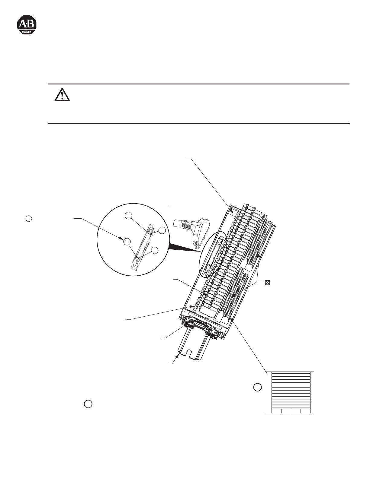
16 And 32 Point Relay Interface Modules
Modules d'interface de relais 16 un 32 points
16 un 32-Punkt-Schnittstellen-Relaismodule
Moduli di interfaccia con relè a 16 un 32 punti
Módulos de interfaz de relé (16 un 32puntos)
(Cat 1492-XIMTS2024-16R; 1492-RXIMTS2024-16R;
1492-XIMTS4024-32R; 1492-RXIMTS4024-32R)
WARNING: To prevent electrical shock, disconnect from power source before installing or servicing.
AVERTISSEMENT
WARNUNG
AVVERTENZA
ADVERTENCIA
1492-XIMTS4024-32R MODULE SHOWN.
: Avant le montage et la mise en service, couper l'alimentation secteur pour éviter toutes décharges.
: Vor Installations- oder Servicearbeiten Stromversorgung unterbrechen, um Elektroschocks zu vermeiden.
: Per prevenire infortuni, togliere tensione prima dell’installazione o manutenzione.
:
Desconéctese de la corriente eléctrica, antes de la instalación o del servicio, a fin de impedir sacudidas eléctricas.
Module Identification Area.
Identification du module.
Modulkennzeichnungsbereich
Area per l'identificazione del modulo
Area de identificación del módulo.
= Connector Pin
= Broche de connexion
= Steckerstift
= Pin del connettore
= Pasador de conector
Status Indicator Relay Active
Voyant d'état de Relais Actif
Statusanzeigerelais Aktiv
Relay Indicatore di Stato Attivo
El Relé del Indicador de Estado Está Activo
40
2
1492-EAJ35
35 mm DIN Rail
199-DR1
199-DR4
1492-DR7
1
39
Relay
Relasi
Relasi
Relay
Relés
= Field-side Terminals
= Borne exterieure
= Feldseitiger Terminal
= Terminale lato-campo
= Terminal de campo
1
PN-90363
DIR 10000135242 (Version 01)
Publication 1492-IN103B-MU-E
Printed in U.S.A.
Adhesive Label Card. Provides terminal wiring identification.
1
Carte étiquette adhésive. Identifie le câblage des bornes.
Aufklebbare Etiketten zur Kennzeichnung der Klemmenverdrahtung.
Scheda etichette adesive. Fornisce l'identificazione del cablaggio dei terminali.
Tarjeta de etiquetas adhesivas. Proporciona identificación de cableado del terminal.
Page 2
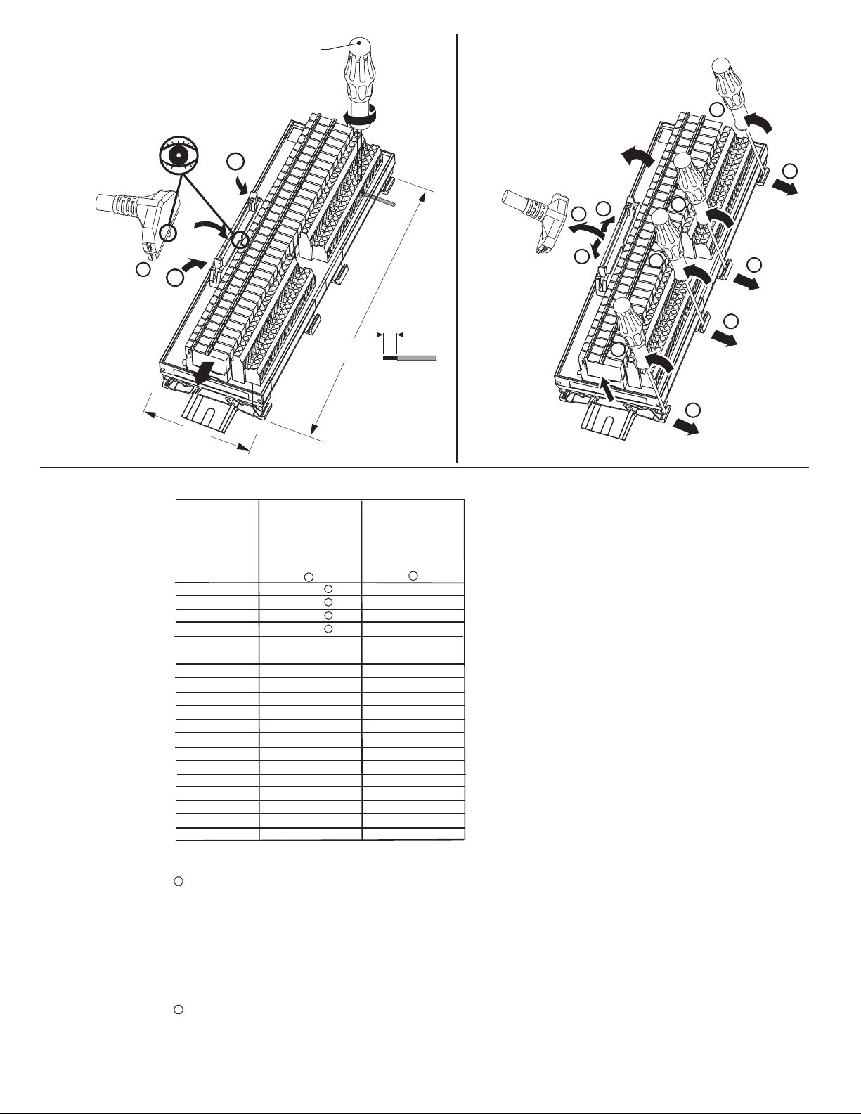
Installation
Montage
Installation
Montaggio
Instalación
1492-N90
4.5 - 5.5 lb-in
(0.50 -0.60 Nm)
Removal
Retrait
Entfernen
Smontaggio
Extracción
10
Cable Matrix
Matrice des câbles
Kabelmatrix
Matrice cavi
Matriz de cables
2
1
2
0.32 in
(8 mm)
#22-#12 AWG
2
(0.2-4 mm
Cu only
Cu seulement
nur Cu
Solo Cu
Cu solamente
)
H
I/O Module
Module E/S
1492-XIMTS2024-16R
1492-RXIMTS2024-16R
W
1492-XIMTS4024-32R
1492-RXIMTS4024-32R
E/A-Modul
Modulo I/O
Módulo de E/S
1746-OB16
1746-OB16E
1746-OB16P
1756-OB16E
1769-OB16
2
1492-CABLE E
1492-CABLE E
1492-CABLE E
1492-CABLE X
1
1
1
1
1492-CAB E69
1769-OB32 1492-CAB K69
1769-OB32T 1492-CABLE H
1756-OB16E 1492-CABLE X
1771-OBD 1492-CABLE F,FF
1746-OB32 1492-CABLE H
1746-OB32E 1492-CABLE H
1756-OB32 1492-CABLE Z
1756-OV32E 1492-CABLE Z
TC-ODD321 1492-CABLE Z
1771-OBN 1492-CABLE
1794-OB16 A94
1794-OB16P A94
1492-CAB
1492-CAB
1794-OB32P 1492-CAB B94
2
L
9
1
2
1
4
8
6
3
7
5
1
Cables are available in 0.5m, 1.0m, 2.5m and 5.0m lengths (005=0.5m, 010=1.0m, 025 = 2.5m, 050=5.0m).
Custom length cables also available. Contact local Sales Office for more information.
Câbles disponibles en 0,5m, 1,0m, 2,5m et 5,0m de longueur (005=0,5m; 010=1,0m; 025=2,5m; 050=5,0m).
Câbles sur mesure à la demande. Contactez e bureau le plus proche.
Verfügbare Kabellängen 0,5m, 1,0m, 2,5m und 5,0m (005=0,5m; 010=1,0m; 025=2,5m; 050=5,0m).
Anwenderspezifizifische Längen stehen ebenfalls zur Verfügung. Kontaktieren Sie bitte Ihr lokales Vertriebsbüro
für weitere Informationen.
I cavi sono disponibili in lunghezze di 0,5m, 1,0m, 2,5m e 5,0m (005=0,5m; 010=1,0m; 025=2,5m; 050=5,0m).
Sono disponibili anche cavi su misura. Per ulteriori informazioni, contattare l’ufficio vendite locale.
Cables disponibles en longitudes de 0,5m, 1,0m, 2,5m, 5,0m (005=0,5m; 010=1,0m; 025=2,5m; 050=5,0m).
Hay disponibles cables de varias longitudes. Para más información comuníquese con la oficina de ventas.
2
Cable is limited for use within the control panel unless it is run through conduit. Cable is ITC (Instrumentation Tray Cable) rated.
PN-90363
DIR 10000135242 (Version 01)
Publication 1492-IN103B-MU-E
(2)
Page 3

I/O Wiring Data
IMPORTANT:
Wiring information for your I/O module, XIM module and cable (e.g. wiring diagram and pinouts) are available online at www.rockwellautomation.com/en/e-tools.
To obtain information follow this procedure.
1) In the Catalog Number BOX at the above online site type in the catalog number of the XIM, RXIM etc. module you are using and click on Submit.
2) At the next screen displayed, click on the Modify key (lower left of screen).
3) Click on the areas that indicate NO SELECTION and enter your specific configuration information (e.g. I/O platform, I/O MODULE, ETC.).
NOTE: To obtain the wiring diagram, you must select the Pre-Wired Cable Connector selection.
4) Configure your 1492 cable by filing in the NO SELECTION areas.
5) Click on the ACCEPT key for the configured 1492 cable. At the next screen click on ACCEPT for the 1492 module.
6) The next screen (Configuration Results) displays the results of your specific configuration. The "supplementary Documents" column contains I/O wiring
information for the configuration (e.g. I/O Wiring Diagrams).
Pinout
Brochage
1492-XIMTS2024-16R
1492-RXIMTS2024-16R
1492-XIMTS4024-32R
1492-RXIMTS4024-32R
Anschlußbelegung
Disposizione dei piedini
Esquema de pins
=
Field-side Terminal
= Borne extérieure
= Feldseitiger Terminal
= Terminale lato-campo
= Terminal de campo
= Relay
= Relasi
= Relasi
= Relay
= Relés
CN
3
4
5
6
7
8
9
10
11
12
13
14
15
16
17
18
~
~
~
~
~
~
~
~
~
~
~
~
~
~
~
~
~
~
~
~
~
~
~
~
~
~
~
~
~
~
~
~
20
COM
19
1
DC (+)
2
TB1
~
A3
K0
A4
A5
K1
A6
A7
K2
A8
A9
A10
K3
A11
K4
A12
A13
K5
A14
A15
K6
A16
A17
K7
A18
B3
K8
B4
B5
K9
B6
B7
K10
B8
B9
B10
K11
B11
K12
B12
B13
K13
B14
B15
K14
B16
B17
K15
B18
A19
A20
User installed jumper
A1
A2
TB1
B1
B2
User installed jumper User installed jumper User installed jumper
B19
B20
CN
5
7
9
11
13
15
17
19
21
23
25
27
29
31
33
35
37
39
38
40
~
~
~
~
~
~
~
~
~
~
~
~
~
~
~
~
~
~
~
~
~
~
~
~
~
~
~
~
~
~
~
COM DC (+)
ROW A
K0
K1
K2
K3
K4
K5
K6
K7
ROW B
K8
K9
K10
K11
K12
K13
K14
K15
TB1
TB1
B20
A19
A3
A4
A5
A6
A7
A8
A9
A10
A11
A12
A13
A14
A15
A16
A17
A18
B3
B4
B5
B6
B7
B8
B9
B10
B11
B12
B13
B14
B15
B16
B17
B18
B19
B20
B19
A20
A19
A20
TB1
TB2
TB1
TB2
CN
6
8
10
12
14
16
18
20
22
24
26
28
30
32
34
36
1
3
2
4
TB2
~
~
~
~
~
~
~
~
~
~
~
~
~
~
~
~
ROW A
K16
K17
K18
K19
K20
K21
K22
K23
A3
A4
A5
A6
A7
A8
A9
A10
A11
A12
A13
A14
A15
A16
A17
A18
TB2
~
~
~
~
~
~
~
~
~
~
~
~
~
~
~
~
ROW B
K24
K25
K26
K27
K28
K29
K30
K31
B2
A1
B3
B4
B5
B6
B7
B8
B9
B10
B11
B12
B13
B14
B15
B16
B17
B18
B1
TB1
B2
B1
TB2
TB1
A2
A1
TB2
A2
PN-90363
DIR 10000135242 (Version 01)
Publication 1492-IN103B-MU-E
(3)
Page 4

Pinout
Brochage
Anschlußbelegung
Disposizione dei piedini
Esquema de pins
Terminal Identification Convention
Convention d’identification des bornes
Klemmenbezeichnungskonvention
Convenzioni per l’identificazione dei morsetti
Convención de identificación del terminal
20
19
2
1
CN
20B
20A
TB1
1492-XIMTS2024-16R
1B
1A
40
CN
2
1
39
1492-RXIMTS2024-16R
20B
20A
PN-90363
DIR 10000135242 (Version 01)
Publication 1492-IN103B-MU-E
TB2
1A
1B
20B
20A
TB1
1B
1A
1492-XIMTS4024-32R
1492-RXIMTS4024-32R
(4)
Page 5

700-TBS24
Relay Contact Rating
Spécification du Contact à Relais
Capacidad Nominal del Contacto de Relé
WARNING: Explosion Hazard.
Do not disconnect equipment unless power has been switched off or the area is known to be non-hazardous.
This equipment is suitable for use in Class I, Division 2, Groups A,B,C and D or non-hazardous locations only.
suitability for Class I, Division 2. Power, input and output (I/O) wiring must be in accordance with Class I, Div. 2 wiring methods - Article 501 - 10 (B) (1)
of the National Electrical Code.
Electrical Ratings
ORDINARY LOCATIONS
HAZARDOUS LOCATION
Ind. Cont. Eq. for Haz. Loc.
Listed A196
Class I, Div.2, Groups A,B,C,D
Class I, Zn2, Groups IIC
Relaiskontakt-Nennwerte
Classificazione Contatti di Relay
Substitution of components may impair
Listed Ind. Cont. Eq. A191
Rated Thermal Current (I
Rated Insulation Voltage (Ui ) 250V IEC, 300V UL/CSA
Output
Maximum Module Current
)
th
Load Voltage Range 0...24VDC
Max. Repetitive Blocking Voltage
Max. Switching Current
On State Voltage Drop @ Max.
Switching Current
Leakage Current
1-Pole, 1 N.O. 1A
33 V
0.75 A DC Ta 0°C - 40°C
0.5 A DC Ta 0°C - 50°C
< 120mVDC
max. 100μA (@U=24V)
· 0.75 Amp per relay output
Replacement Relays
24VDC Control Voltage: 700-TBS24
·
PN-90363
DIR 10000135242 (Version 01)
Publication 1492-IN103B-MU-E
(5)
Page 6

Specifications
Spécifications
Catalog No.
Référence
Bestell-Nr.
N. Catalogo
Referencia
1492-XIMTS2024-16R
1492-RXIMTS2024-16R
1492-XIMTS4024-32R
1492-RXIMTS4024-32R
Technische Daten
Specifiche
Voltage
Tension
Spannung
Tensione
Voltaje
Indicator Circuit Current
Courant circuit voyants
Strom, Anzeigeschaltkreis
Corrente circuito indicatori
Intensidad del circuito de
indicadores
Especificaciones
2.0 mA20 - 26 VDC
Maximum Recurring Peak Voltage
Tension de crele réurrente maximale
Maximale periodische Hochstspannung
Tensione massima di cresta ricorrente
Voltaje de cresta iterativo máximo
600 V
p
Catalog No.
Référence
Bestell-Nr.
N. Catalogo
Referencia
1492-XIMTS2024-16R
1492-RXIMTS2024-16R
1492-XIMTS4024-32R
1492-RXIMTS4024-32R
Operating Temperature Range
Plage températures de fonctionnement
Betriebstemperaturbereich
Limiti temperatura di funzionamento
Rango de temperatura de funcionamient
0° C - 60° C
Operating Humidity
Humidité relative
Betriebsluftfeuchtigkeit
Umidità di esercizio
Humedad operativa
5 - 95%
Approx. Shipping Weight
Poids d'embarquement approximatif
Ungefähres Versandgewicht
Peso approssimativo del carico
Peso aproximado al momento de
embarque
1.55 lb.
398 g.
.880 lb.
701 g.
Dimensions
Dimensions
Abmessungen
Dimensioni
Dimensiones
4.72 in. (120 mm) W
3.27 in. (83 mm) H
2.74 in (70.5 mm) D
9.45 in. (240 mm) W
3.27 in. (83 mm) H
2.74 in (70.5 mm) D
Standards
Normes
Standards
Standard
Estándares
cULus (File: E113724, Guide No.: NRAQ)
CE: Compliant for all applicable directives
For transients > 600 Vp use a UL recognized suppression device rated at 2.5 kV withstand.
Pour des transitoires > 600 Vp utilisez un dispositif de suppression certifié UL à 2,5 kV nominal de tenue.
Für Einschaltstöße > 600 Vp verwenden Sie einen UL anerkannten Entstörer, der bewertet wurde bei 2,5 kV standzuhalten.
Per transitori > 600 Vp usare dispositivo di soppressione riconosciuto da UL capace di sopportare 2,5 kV.
Para transitorios > 600 Vp use un dispositivo de supresión reconocido UL clasificado con 2,5 kV.
Non-condensing
Sans condensation
Nicht kondensierend
Senza condensa
sin condensación
Add 0.39 in. to the width dimension for 1492-Rxx type modules.
SURGE SUPPRESSION follow the literature recommendations of the PLC module being used.
SUPPRESSION DES SURTENSIONS se trouve à la suite de la littérature qui contient les recommandations relatives au module PLC utilisé.
ÜBERSPANNUNGSSCHUTZ Bitte beachten Sie die Dokumentationsempfehlungen für das jeweils benutzte SPS-Modul.
Per la SOPPRESSIONE DEI PICCHI TEMPORANEI, seguire le istruzioni riportate nella documentazione in dotazione al Modulo PLC utilizzato.
SUPRESIÓN DE SOBRETENSIÓN, siga las recomendaciones indicadas en la documentación del módulo PLC respectivo.
relay socket
24595-110-01
Reference Publications: Refer to 1770-4.1 and appropriate PLC I/O module installation manual.
PN-90363
DIR 10000135242 (Version 01)
Publication 1492-IN103B-MU-E
Printed in U.S.A.
 Loading...