

Page 1
Isolated Fusible Interface Modules
Modules d’interface à fusibles isolés
Isolierte Schnittstellenmodule mit Sicherung
Moduli d’interfaccia con fusibili isolati
Módulos aislados de interface con fusible
(Cat 1492-IFM20F-FS-2, -IFM20F-FS24-2, -IFM20F-FS120-2, -IFM40F-FS-2, -IFM40F-FS24-2,
-IFM40F-FS120-2, -RIFM40F-FS120-2, -IFM40F-F24D-2)
WARNING
AVERTISSEMENT
WARNUNG
AVVERTENZA
ADVERTENCIA
Fuse Clips and Blown Fuse Indicators: See page 4 for fuse installation/removal.
Porte-fusibles et voyants de fusibles grillés: voir page 4 l'installation et le retrait des fusibles.
Sicherungshalterungen und Anzeige einer durchgebrannten Sicherung. Ein-und Ausbau der Sicherung siehe Seite 4.
Morsetti dei fusibili e indicatori dei fusibili bruciati: vedere il montaggio/smontaggio dei fusibili a pagina 4.
Sujetadores de fusibles e indicadores de fusible fundido: Vea la página 4 para obtener información sobre la instalación/extracción de fusibles.
To prevent electrical shock, disconnect from power source before installing or servicing.
device installation in a tool-accessible enclosure compliant with ANSI/ISA S82.
Avant le montage et la mise en service, couper l'alimentation secteur pour éviter toutes décharges.
nécessite l'installation de l'équipement dans une armoire accessible aux interventions, conforme à ANSI/ISA S82.
Vor Installations- oder Servicearbeiten Strom-versorgung unterbrechen, um Elektroschocks zu vermeiden.
Gruppe 2 erfordert die Installation des Gerätes in einem Gehäuse, das für Werkzeuge zugänglich ist und den
Anforderungen gemäß ANSI/ISA S82 entspricht.
Per prevenire infortuni, togliere tensione prima dell’installazione o manutenzione.
l'installazione del dispositivo in un alloggiamento con capacità di accesso per strumenti conforme allo standard
ANSI/ISA S82.
Desconéctese de la corriente eléctrica, antes de la instalación o del servicio, a fin de impedir sacudidas eléctricas.
requisito de FM (Factory Mutual) Clase 1, Div. 2, establece que el dispositivo debe instalarse en un envolvente que
permita la introducción y uso de herramientas y cumpla con la norma ANSI/ISA S82.
FM Classe 1, Divisione 2 richiede
FM Class 1, Div.2 requires
FM Classe 1, Div. 2
FM-Klasse 1,
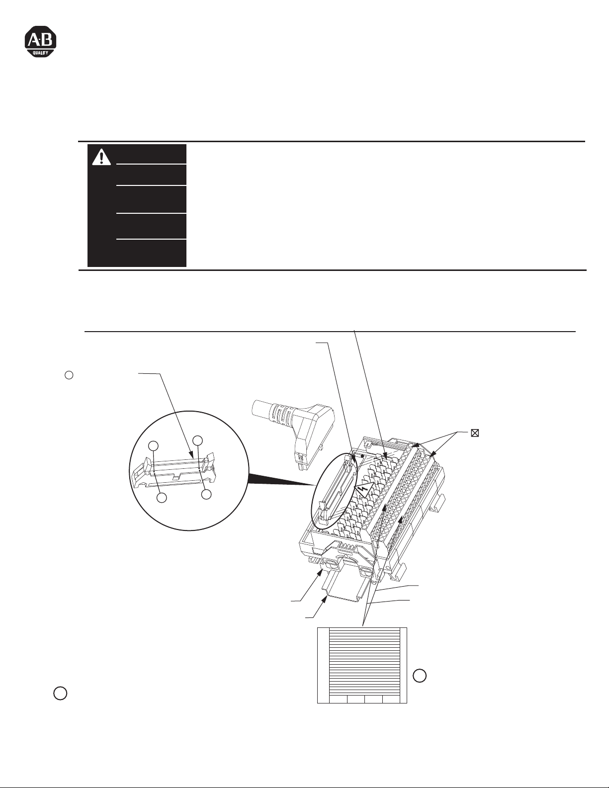
Module Identification Area.
Identification du module.
Modulkennzeichnungsbereich
= Connector Pin
= Broche de connexion
Area per l'identificazione del modulo
Area de identificación del módulo.
= Steckerstift
= Pin del connettore
= Pasador de conector
20
2
(IFM40...)
= Field-side Terminals
= Borne exterieure
= Feldseitiger Terminal
= Terminale lato-campo
= Terminal de campo
(IFM20...)
1
19
El
Adhesive Label Card. Provides terminal wiring identification.
1
Carte étiquette adhésive. Identifie le câblage des bornes.
Aufklebbare Etiketten zur Kennzeichnung der Klemmenverdrahtung.
Scheda etichette adesive. Fornisce l'identificazione del cablaggio dei terminali.
Tarjeta de etiquetas adhesivas. Proporciona identificación de cableado del terminal.
PN-23248
DIR 40063-316 (Version 13)
Printed in U.S.A.
1492-EAJ35
35 mm DIN Rail
199-DR1
199-DR4
1492-DR7
B1
A1
Lower = A
Upper = B
1
Page 2
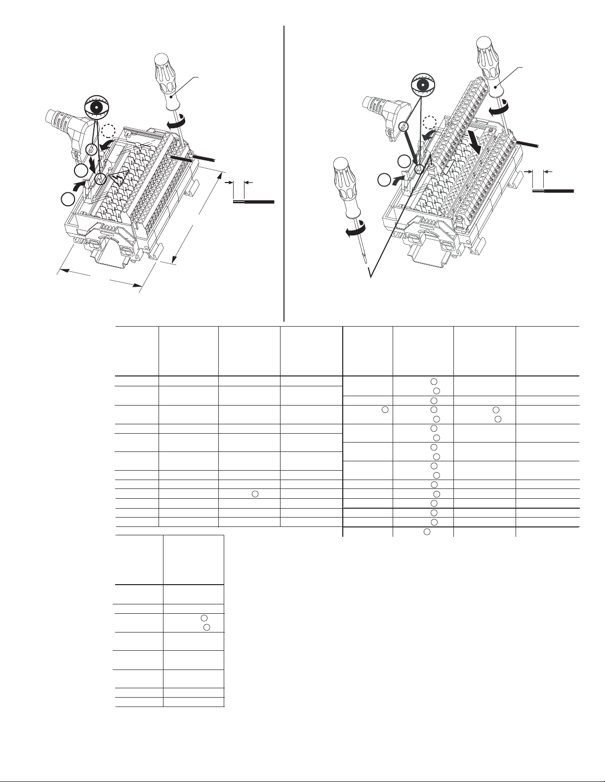
Module
Installation / Removal
Montage / Retrait
Installation / Entfernen
Montaggio / Smontaggio
Instalación / Extracción
2
1492-N90
3.5-4.5 lb-in
(0.38-0.50 Nm)
Removable Terminal Block
Installation / Removal
Montage / Retrait
Installation / Entfernen
Montaggio / Smontaggio
Instalación / Extracción
1492-N90
3.5-4.5 lb-in
(0.38-0.50 Nm)
2
1
2
H
Applies to modules with fixed and
removable (R) terminal block
Cable Matrix
Matrice des câbles
Kabelmatrix
Matrice cavi
Matriz de cables
PN-23248
DIR 40063-316 (Version 13)
I/O Module
Module E/S
E/A-Modul
Modulo I/O
Módulo de E/S
1746-OX8
1756-OA8
TC-ODC081
1756-OA8D
TC-ODX081
1756-OA8E
1756-OB8
TC-ODD081
1756-OC8
TC-ODE081
1756-ON8
1769-OA8
1769-OW8
1769-OW8I
1794-OW8
I/O Module
Module E/S
E/A-Modul
Modulo I/O
Módulo de E/S
1756-OA16I
TC-ODK161
1756-OB8EI
1756-OB16D
TC-ODX161
1756-OB16I
TC-ODJ161
1756-OH8I
TC-ODF081
1756-OW16I
TC-ORC161
1756-OX8I
TC-ORC081
0.32 in
(8 mm)
W
#22-#12 AWG
2
(0.2-4 mm
)
Cu only
Cu seulement
nur Cu
Solo Cu
Cu solamente
S
W
W
W
W
W
1
1492-IFM20F-FS120-2
1492-CABLE
1492-CABLE
1492-HWCAB
1492-CABLE
1492-HWCAB
1492-CABLE
S
W
W
V
V
V
1492-CABC69
1492-CABC69
1492-IFM20F-FS-2 1492-IFM20F-FS24-2
1492-CABLE
1492-CABLE
1492-HWCAB
1492-CABLE
1492-HWCAB
1492-CABLE
1492-CABLE
1492-HWCAB
1492-CABLE
1492-HWCAB
1492-CABLE
1492-CABC69
1492-CABC69
1492-CABD69 1492-CABD69 1492-CABD69
1492-CABA94 1492-CABA94 1492-CABA94
S
W
W
V
V
V
W
W
W
W
W
1492-CABLE
1492-CABLE
1492-HWCAB
1492-CABLE
1492-HWCAB
1492-CABLE
1492-CAB C69
Cables are available in 0.5m, 1.0m, 2.5m and 5.0m lengths (005=0.5m, 010=1.0m, 025 = 2.5m, 050=5.0m).
1492-IFM40F-F24D-2
Custom length cables also available. Contact local Sales Office for more information.
Câbles disponibles en 0,5m, 1,0m, 2,5m et 5,0m de longueur (005=0,5m; 010=1,0m; 025=2,5m; 050=5,0m).
Câbles sur mesure à la demande. Contactez e bureau le plus proche.
Verfügbare Kabellängen 0,5m, 1,0m, 2,5m und 5,0m (005=0,5m; 010=1,0m; 025=2,5m; 050=5,0m).
Anwenderspezifizifische Längen stehen ebenfalls zur Verfügung. Kontaktieren Sie bitte Ihr lokales Vertriebsbüro
für weitere Informationen.
1492-CABLE
1492-HWCAB
1
Y
1
I cavi sono disponibili in lunghezze di 0,5m, 1,0m, 2,5m e 5,0m (005=0,5m; 010=1,0m; 025=2,5m; 050=5,0m).
Y
Sono disponibili anche cavi su misura. Per ulteriori informazioni, contattare l’ufficio vendite locale.
Cables disponibles en longitudes de 0,5m, 1,0m, 2,5m, 5,0m (005=0,5m; 010=1,0m; 025=2,5m; 050=5,0m).
Hay disponibles cables de varias longitudes. Para más información comuníquese con la oficina de ventas.
The 1492-IFM40F-FS24-2 module and 1492-CABLE(1)Y cable can be used with the 1756-OB16D module.
However, due to the 1492-IFM40F-FS24-2 modules blown fuse leakage current rating, the "no load" diagnostic
function of the 1756-OB16D will not indicate a blown or removed fuse as a no load condition. If you require this
diagnostic to function for a blown or removed fuse you must use a 1492-IFM40F-F24D-2.
Supports Removable Terminal Block (RTB) plugs. Compatible screw type plug, 1492-RTB20N (pkg. qty. 2).
Compatible push-in style plug, 1492-RTB20P (pkg. qty. 2). Order plugs separately.
Cable is limited for use within the control panel unless it is run through conduit.
Cable is ITC (Instrumentation Tray Cable) rated.
(2)
1
2
#22-#12 AWG
(0.2-4 mm
Cu only
Cu seulement
nur Cu
Solo Cu
Cu solamente
Applies to modules with
removable terminal block plugs (1492-RIFM_)
I/O Module
Module E/S
E/A-Modul
Modulo I/O
Módulo de E/S
1756-OA16I
TC-ODK161
1756-OB8EI
1756-OB16D
TC-ODX161
1756-OB16I
TC-ODJ161
1756-OH8I
TC-ODF081
1756-OW16I
TC-ORC161
1756-OX8I
TC-ORC081
1771-OD16
1771-ODD
1771-OQ16
1771-OW16
1492-IFM40F-FS-2
1492-CABLE
1492-HWCAB
1492-CABLE
2
1492-CABLE
1492-HWCAB
1492-CABLE
1492-HWCAB
1492-CABLE
1492-HWCAB
1492-CABLE
1492-HWCAB
1492-CABLE
1492-HWCAB
1492-CABLE
1492-CABLE
1492-CABLE
1492-CAB
1
Y
Y
1
Y
1
Y
Y
1
Y
1
1
1
1
1
1
1
R71
1492-IFM40F-FS24-2 1492-IFM40F-FS120-2
1492-RIFM40F-FS120-2
1492-CABLE
1
1
1
Y
Y
1
Y
Y
1
Y
Y
1
Y
M
M
M
1492-CABLE
1492-CABLE
1492-HWCAB
1492-CABLE
1492-HWCAB
1492-CABLE
1492-HWCAB
1492-CABLE
1492-HWCAB
1492-CABLE
1492-CAB
R71
Y
1
Y
Y
Y
Y
Y
Y
M
Y
1
Y
1492-HWCAB
1492-CABLE
1492-HWCAB
1492-CABLE
1492-HWCAB
1492-CABLE
1492-HWCAB
1492-CABLE
1492-CABLE
1492-CAB
0.32 in
(8 mm)
Y
Y
Y
Y
M
M
R71
Y
Y
Y
Y
2
)
Ê
Page 3

Pinout
Brochage
Anschlußbelegung
Disposizione
dei piedini
Esquema de pins
10
3
5
(odd) 3
15
17
20
1
2
4
6
8
12
14
16
18
19
Odd
Impair
Ungerade
Dispari
Impar
1492-IFM20F-FS-2
1492-IFM20F-FS24-2
1492-IFM20F-FS120-2
1492-IFM20F-FS24-2
1492-IFM20F-FS120-2
(ONLY)
B1
B2
B3
B8
B9
B10
A1
A2
A3
A4
A5
A6
A7
A8
A9
A10
6
(even)
36
5
(odd)
35
6
(even)
36
5
(odd)
35
Odd
Impair
Ungerade
Dispari
Impar
1492-IFM40F-FS-2
1492-IFM40F-FS24-2
1492-IFM40F-FS120-2
1492-RIFM40F-FS120-2
Even
Pair
Gerade
Pari
Par
B3
B18
A3
A18
B3
B18
A3
A18
I/O Wiring Data
NOTICE
Blown Fuse Indicator Circuit
Circuit du voyant de rupture de fusible
Anzeigeschaltung für durchgebrannte Sicherung
Indicatore dei fusibili bruciati
Circuito del indicador de fusible fundido
6
(even)
36
21
7B2
9
11
13
15
17
Blown Fuse Indicator Circuit
Circuit du voyant de rupture de fusible
Anzeigeschaltung für durchgebrannte Sicherung
Indicatore dei fusibili bruciati
Circuito del indicador de fusible fundido
23 B20
25
27
29
31
33
Wiring information for your I/O module, AIFM module and cable (e.g. wiring diagram and pinouts)are available online at www.rockwellautomation.com/en/e-tools.
To obtain information follow this procedure.
1) In the Catalog Number BOX at the above online site type in the catalog number of the IFM, AIFM, etc. module you are using and click on Submit.
2) At the next screen displayed, click on the Modify key (lower left of screen).
3) Click on the areas that indicate NO SELECTION and enter your specific configuration information (e.g. I/O platform, I/O MODULE, ETC.).
NOTE: To obtain the wiring diagram, you must select th Pre-Wired Cable Connector selection.
4) Configure your 1492 cable by filing in the NO SELECTION areas.
5) Click on the ACCEPT key for the configured 1492 cable. At the next screen click on ACCEPT for the 1492 module.
6) The next screen (Configuration Results) displays the results of your specific configuration. The "supplementary Documents" column contains I/O wiring information
for the configuration (e.g. I/O Wiring Diagrams).
1492-IFM40F-F24D-2
B3
B18
B195B1
19 A10
COM +V
Blown Fuse Indicator Circuit
Circuit du voyant de rupture de fusible
Anzeigeschaltung für durchgebrannte Sicherung
Indicatore dei fusibili bruciati
Circuito del indicador de fusible fundido
A1
A2
A3
A4
A5
A6
A7
A8
A9
35 A20
A11
A12
A13
A14
A15
A16
A17
A18
A19
PN-23248
DIR 40063-316 (Version 13)
(3)
Page 4

Fuse Installation/Removal
Installation/retrait des fusibles
Ein- und Ausbau der Sicherung
Montaggio/smontaggio dei fusibili
Instalación/extracción de fusibles
5 x 20 mm
(max. 2.0A per output; 12A per module)
(2,0 A par sortie maximum; 12 A par module)
(max. 2,0 A je Ausgang, 12 A je Modul)
(max 2 A per uscita; 12 A per modulo)
1
2
1
GOULD 34-015G
LITTELFUSE 097023
BUSSMAN FP-A3
(2,0 A máx. por salida; 12 A por módulo)
3
2
4
Specifications
Spécifications
Catalog No.
Référence
Bestell-Nr.
N. Catalogo
Referencia
1492-IFM20F-FS-2
1492-IFM20F-FS24-2
1492-IFM20F-FS120-2
1492-IFM40F-FS-2
1492-IFM40F-FS24-2
1492-IFM40F-FS120-2
1492-RIFM40F-FS120-2
1492-IFM40F-F24D-2
Catalog No.
Référence
Bestell-Nr.
N. Catalogo
Referencia
1492-IFM20F-FS-2
1492-IFM20F-FS24-2
1492-IFM20F-FS120-2
1492-IFM40F-FS-2
1492-IFM40F-FS24-2
1492-IFM40F-FS120-2
1492-RIFM40F-FS120-2
1492-IFM40F-F24D-2
Technische Daten
Specifiche
Voltage
Tension
Spannung
Tensione
Voltaje
0 - 132V AC/DC
10 - 30V AC/DC
85 - 132V AC/DC
0 - 132V AC/DC
10 - 30V AC/DC
85 - 132V AC/DC
85 - 132V AC/DC
10 - 30V DC
Maximum Recurring Peak Voltage Ê
Tension de crele réurrente maximale
Maximale periodische Hochstspannung
Tensione massima di cresta ricorrente
Voltaje de cresta iterativo máximo
Current/Circuit
Courant/Circuit
Strom/Schaltkreis
Corrente/circuito
Intensidad/circuito
p Ê
600 V
2 Amps
Especificaciones
Current/Module
Courant/Module
Strom/Modul
Corrente/modulo
Intensidad/módulo
12 Amps
8 Amps
Humidity
Humidité
Feuchtigkeit
Humedad
Umidità
5 - 95% Ê
Approx. Shipping Weight
Poids d'embarquement approximatif
Ungefähres Versandgewicht
Peso approssimativo del carico
Peso aproximado al momento de
embarque
Indicator Circuit Current
Courant circuit voyants
Strom, Anzeigeschaltkreis
Corrente circuito indicatori
Intensidad del circuito
de indicadores
< 0.05mA
.51 lb.
(233 g.)
.76 lb.
(346 g.)
N/A
2.0mA
2.5mA
N/A
2.0mA
2.5mA
2.5mA
Dimensions Ê
Dimensions
Abmessungen
Dimensioni
Dimensiones
2.36 in. (60 mm) W
3.27 in. (83 mm) H
2.78 in (70.5 mm) D
4.72 in. (120 mm) W
3.27 in. (83 mm) H
2.78 in (70.5 mm) D
Operating Temperature Range
Plage températures de fonctionnement
Betriebstemperaturbereich
Limiti temperatura di funzionamento
Rango de temperatura de funcionamient
0° C - 60° C
Standards
Normes
Standards
Standard
Estándares
cULus (File: E10314, Guide No. NRAG)
Suitable for use in Class 1 Div 2 Groups A,
B, C and D Hazardous and Non-Hazardous
Locations.
Temperature Code = T3C at 60°C Ê
CE: Compliant for all applicable directives
FM Class 1 Div 2 Groups A, B, C and D
Temperature Rating T3C = 60°C (J.I. 3000590,
all except relay modules)
For transients > 600 Vp use a UL recognized suppression device rated at 2.5 kV withstand.
Pour des transitoires > 600 Vp utilisez un dispositif de suppression certifié UL à 2,5 kV nominal de tenue.
Für Einschaltstöße > 600 Vp verwenden Sie einen UL anerkannten Entstörer, der bewertet wurde bei 2,5 kV standzuhalten.
Per transitori > 600 Vp usare dispositivo di soppressione riconosciuto da UL capace di sopportare 2,5 kV.
Para transitorios > 600 Vp use un dispositivo de supresión reconocido UL clasificado con 2,5 kV.
Non-condensing
Sans condensation
Nicht kondensierend
Senza condensa
sin condensación
Power, input and output (I/O) wiring must be in accordance with Class I Division 2 wiring methods - Artticle 501-10(B)(1) of the National Electrical Code.
WARNING
Explosion Hazard - substitution of components may impair suitability for Class I Division 2.
Explosion Hazard - Do Not Disconnect Equipment unless power has been switched off or the area is known to be Non-Hazardous.
Add 0.39 in. to the width dimension for 1492-Rxx type modules.
SURGE SUPPRESSION follow the literature recommendations of the PLC module being used.
La section SUPPRESSION DES SURTENSIONS se trouve à la suite de la littérature qui contient les recommandations relatives au module PLC utilisé.
ÜBERSPANNUNGSSCHUTZ Bitte beachten Sie die Dokumentationsempfehlungen für das jeweils benutzte SPS-Modul.
Per la SOPPRESSIONE DEI PICCHI TEMPORANEI, seguire le istruzioni riportate nella documentazione in dotazione al Modulo PLC utilizzato.
SUPRESIÓN DE SOBRETENSIÓN, siga las recomendaciones indicadas en la documentación del módulo PLC respectivo.
Reference Publications: Refer to 1770-4.1 and appropriate PLC I/O module installation manual.
PN-23248
DIR 40063-316 (Version 13)
Printed in U.S.A.
 Loading...