

Page 1
Installation Instructions
Duct Average-temperature
Transmitter
Catalog Numbers
1414-ITX03ACDAA, 1414-ITX02ACDAA, 1414-CTQ03AIEAA,
1414-CTX03PCDAA
Top ic Pa ge
About the Duct Average-temperature Transmitter 1
Important User Information 2
Mount the Duct Average-temperature Transmitter 3
Wire and Connect the Duct Average-temperature
Transmitter
Field Calibration 4
Specifications 5
Dimensions 6
3
About the Duct Average-temperature Transmitter
The multi-point duct average-temperature transmitter incorporates numerous precision RTD
sensors at equal distances. The transmitter is encapsulated in a soft copper probe for long lengths
or a stainless steel probe for shorter lengths. All probes provide excellent heat transfer, fast
response, and moisture-penetration resistance. The transmitter provides a high accuracy signal
with excellent long term stability, low hysteresis, and fast response.
Page 2
2 Duct Average-temperature Transmitter
Important User Information
Solid-state equipment has operational characteristics differing from those of electromechanical equipment.
Safety Guidelines for the Application, Installation and Maintenance of Solid State Controls (Publication SGI-1.1
available from your local Rockwell Automation sales office or online at
http://www.rockwellautomation.com/literature/
equipment and hard-wired electromechanical devices. Because of this difference, and also because of the wide
variety of uses for solid-state equipment, all persons responsible for applying this equipment must satisfy
themselves that each intended application of this equipment is acceptable.
In no event will Rockwell Automation, Inc. be responsible or liable for indirect or consequential damages
resulting from the use or application of this equipment.
The examples and diagrams in this manual are included solely for illustrative purposes. Because of the many
variables and requirements associated with any particular installation, Rockwell Automation, Inc. cannot
assume responsibility or liability for actual use based on the examples and diagrams.
No patent liability is assumed by Rockwell Automation, Inc. with respect to use of information, circuits,
equipment, or software described in this manual.
Reproduction of the contents of this manual, in whole or in part, without written permission of Rockwell
Automation, Inc., is prohibited.
Throughout this manual, when necessary, we use notes to make you aware of safety considerations.
WARNING: Identifies information about practices or circumstances that can cause an
explosion in a hazardous environment, which may lead to personal injury or death, property
damage, or economic loss.
) describes some important differences between solid-state
ATTENTION: Identifies information about practices or circumstances that can lead to personal
injury or death, property damage, or economic loss. Attentions help you identify a hazard, avoid
a hazard and recognize the consequences.
SHOCK HAZARD: Labels may be on or inside the equipment, for example, drive or motor, to
alert people that dangerous voltage may be present.
BURN HAZARD: Labels may be on or inside the equipment, for example, drive or motor, to
alert people that surfaces may reach dangerous temperatures.
IMPORTANT Identifies information that is critical for successful application and understanding of the
product.
Publication 1414-IN004B-EN-P - July 2010
Page 3
Duct Average-temperature Transmitter 3
Mount the Duct Average-temperature Transmitter
Follow these steps to mount the transmitter.
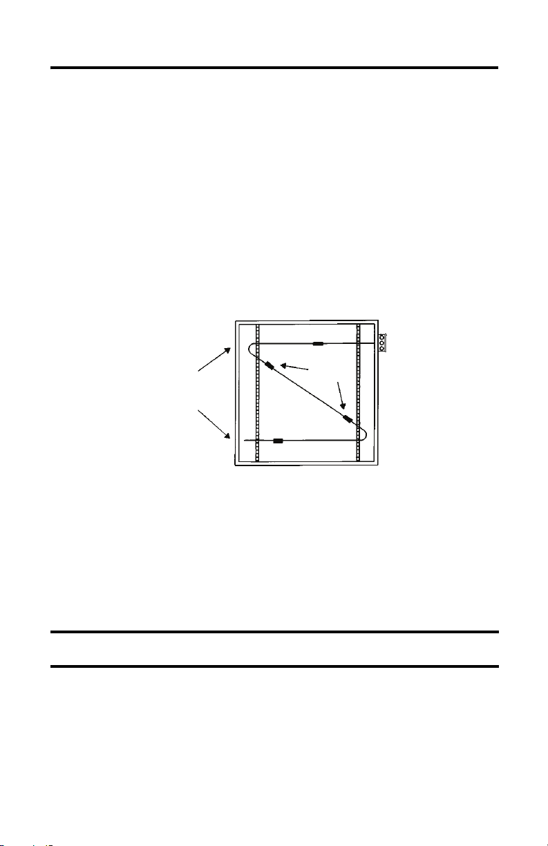
1. Install the duct average sensors onto hangers in the duct using supplied clamps.
Located the sensors in a straight section of duct away from heating, cooling, or
humidifier elements.
The duct average sensor can be easily shaped to fit any duct size, but observe a minimum
bend radius of six inches to prevent damage to wires or sensors. Duct average elements
are not recommended for high humidity applications.
2. Mounted the duct average temperature transmitter enclosure to the outside of the duct,
where the sensor tubing exits the duct, by using sheet metal screws (not supplied).
Placement of a 12 ft Duct Average
Sensor in a 48 in. Square Duct
Use Hangers to Secure
Duct Average
Sensors
Note: 6" Bend
Radius
Wire and Connect the Duct Average-temperature Transmitter
Follow these steps to wire and connect the transmitter.
1. Connect the transmitter to the controller by using twisted 18…22 AWG wire.
The transmitter requires two wires for DC 4…20 mA loop-powered operation. The use
of shielded cable is optional, but recommended for the highest noise immunity.
IMPORTANT
2. Select the controller Analog Input (AI) to match the transmitter output before power is
applied.
The AI type must be a current input with 250 or 500 ohm impedance. All transmitters
have an operating range of 0…70 °C (32…158 °F). The transmitter board should not be
mounted where temperatures exceed these values. See the connection diagram for more
details.
Do not route signal wires in the same conduit with power cables as signal
degradation may occur.
Publication 1414-IN004B-EN-P - July 2010
Page 4
4 Duct Average-temperature Transmitter
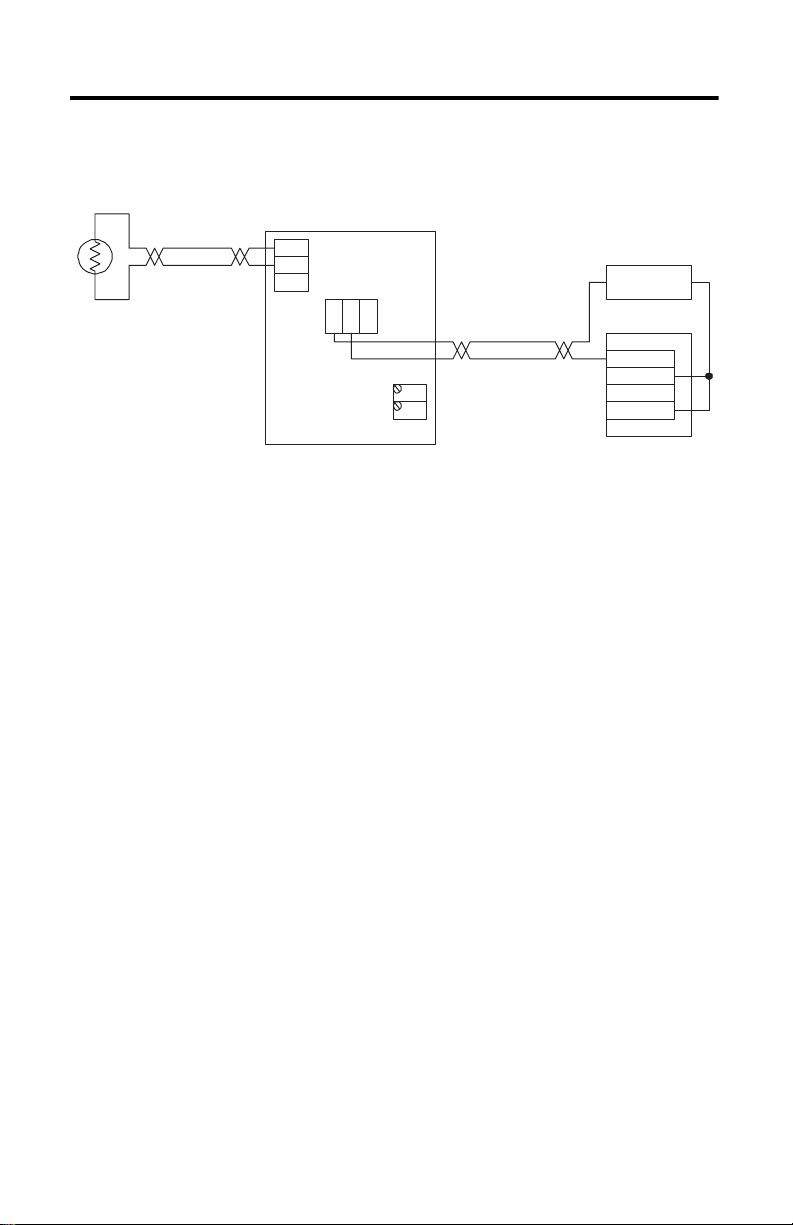
Typical wiring to a controller is shown in the diagram. For 4…20 mA loop signal, only
the PWR and OUT terminals are used.
2-wire RTD
Sensor
Temperature Transmitter
NEG
SEN
EXC
Loop Power Supply
+ 24V DC -
OUT
PWR
COM
SPAN
ZERO
Analog Current Input
ANL IN 0 +
ANL IN 0 -
ANL COM
Field Calibration
The unit can be calibrated in the field by using precision resistor values equal to the zero and
span of the transmitter temperature range.
1. Disconnect the sensor from the transmitter and connect the resistor that represents the
zero value to the EXC and NEG terminals.
TIP
2. Adjust the ZERO pot until the desired output is achieved.
3. Connect the resistor that represents the span value to the EXC and NEG terminals.
4. Adjust the SPAN pot until the desired output is achieved.
Repeat these steps until no further adjustment is required.
If the unit uses a three-wire sensor, a jumper must be placed between EXC and
SEN.
Publication 1414-IN004B-EN-P - July 2010
Page 5

Duct Average-temperature Transmitter 5
Specifications
Technical Specifications - Duct Average-temperature Transmitter
Attribute 1414-ITX03ACDAA, 1414-ITX02ACDAA,
1414-CTQ03AIEAA, 1414-CTX03PCDAA
Standard lengths 20 ft
Operating temperature range 0…70 °C (32…158 °F)
Probe type Flexible copper tube
Wiring connections Terminal blocks
Enclosures Plastic ABS - UL94-V - NEMA 1
Sensor type 1 KΩ Platinum RTD
Cable FT-6 plenum rated cable
Probe 304 Stainless steel straight tip, 6.35 mm (0.25 in.) OD
Output signal 4…20 mA current loop
Transmitter accuracy ±0.1% of span, including linearity
Power supply 15…35V DC
Consumption Current: 22.5 mA Max. (with open sensor)
PCB operating temperature 0…70 °C (32…158 °F)
Wiring connection Screw terminal block (14…22 AWG)
Aluminum - NEMA 3R
Commercial and Hybrid: ±0.3%
Class B Industrial: ±0.2% Class A
Bendable soft copper tubing, 7.94 mm (0.3125 in.) OD
TIP
Duct Temperature Averaging has four sensors on < 20 ft probe length and nine
sensors on 24 ft probe length. A rigid, straight, stainless-steel probe is used on
lengths shorter than 36 in.
Publication 1414-IN004B-EN-P - July 2010
Page 6
6 Duct Average-temperature Transmitter
Available Duct Average-temperature Transmitter, 4…20 mA
Description Commercial Hybrid Industrial with
cc-pcb
Plastic
Enclosure
457 mm (18 in.) probe
-6.7…48.9 °C (20…120 °F)
457 mm (24 in.) probe
-6.7…48.9 °C (20…120 °F)
457 mm (36 in.) probe
-6.7…48.9 °C (20…120 °F)
609.6 cm (20 ft) tubing 0…50 °C (32…122 °F) 1414-CTX03PCDAA 1414-ITX03ACDAA 1414-ITX02ACDAA
609.6 cm (20 ft) tubing 0…100 °C (32…212 °F)
731.52 cm (24 ft) tubing
0…100 °C (32…212 °F)
731.52 cm (24 ft) tubing
-50…50 °C (-58…122 °F)
731.52 cm (24 ft.) tubing
-50…100 °C (-58…212 °F)
Aluminum Enclosure
1414-CTQ03AIEAA
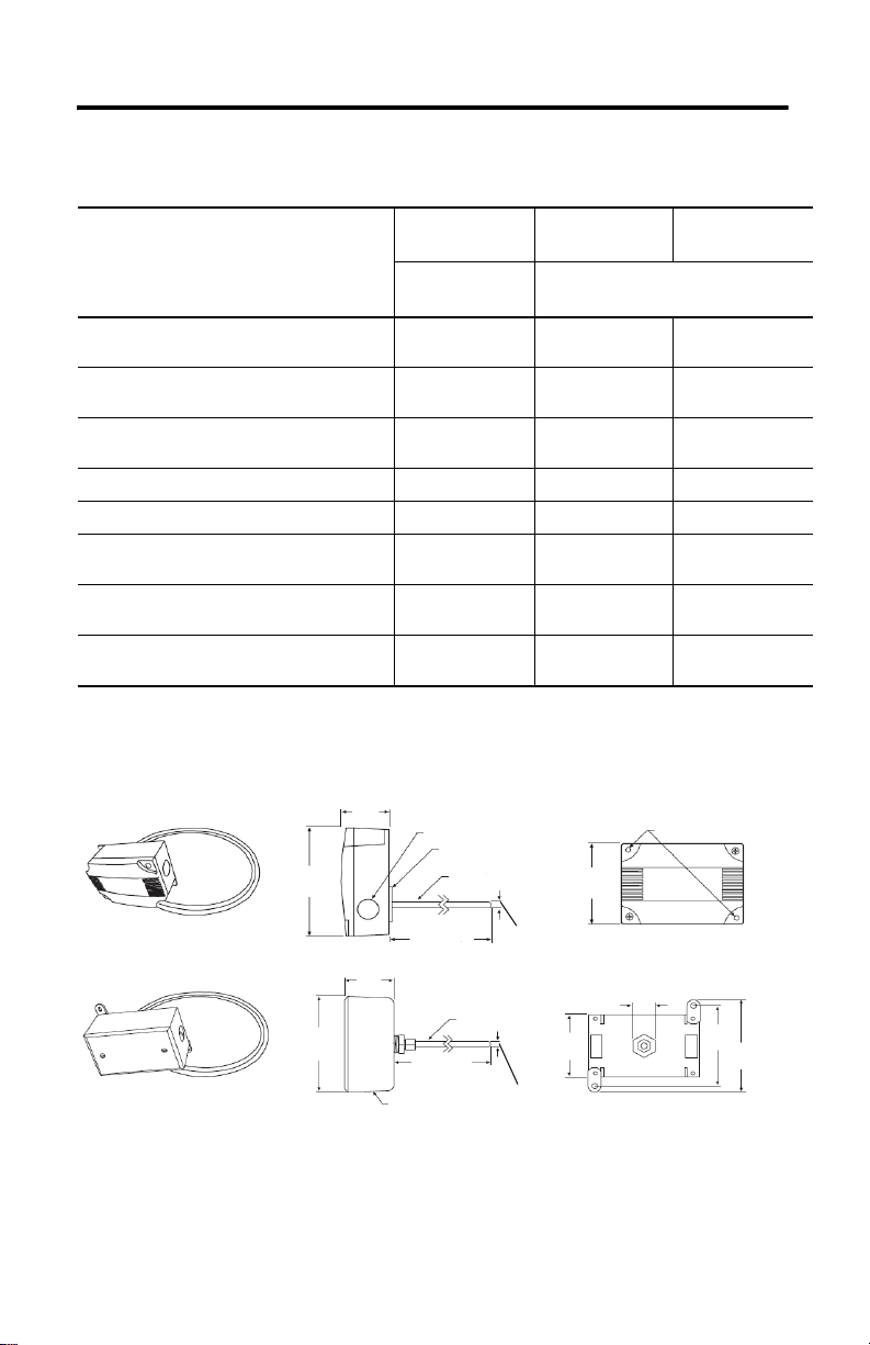
Dimensions
Plastic ABS Enclosure (NEMA 1)
Aluminum Enclosure (NEMA 3R)
Publication 1414-IN004B-EN-P - July 2010
115.8 mm
(4.56 in.)
114.3 mm
(4.50 in.)
53.6 mm
(2.11 in.)
53.9 mm
(2.12 in.)
Conduit Holes
Ø 25. 6 mm (0.85 in.) (2X)
Foam Gasket
Stainless Steel Probe
6.35 mm (0.25 in.) OD
Various Lengths
Stainless Steel Probe
6.35 mm (0.25 in.) OD
Various Lengths
Soft Copper Tubing
Conduit Holes
Ø 12.7 mm (0.50 in.) (2X)
7.94 mm (0.3125 in.) OD
84.3mm
(3.32 in.)
Soft Copper Tubing
7.94 mm (0.3125 in.) OD
72 mm
(2.85 in.)
Mounting Holes
Ø 5.08 mm (0.2 in.) (2X)
25.4 mm
(1.0 in.)
85 mm
(3.35 in.)
96 mm
(3.78 in.)
Page 7

Notes:
Duct Average-temperature Transmitter 7
Publication 1414-IN004B-EN-P - July 2010
Page 8

Rockwell Automation Support
Rockwell Automation provides technical information on the Web to assist you in using its products. At
http://www.rockwellautomation.com/support/
technical and application notes, sample code and links to software service packs, and a MySupport feature that
you can customize to make the best use of these tools.
For an additional level of technical phone support for installation, configuration and troubleshooting, we offer
TechConnect support programs. For more information, contact your local distributor or Rockwell Automation
representative, or visit http://www.rockwellautomation.com/support/
Installation Assistance
If you experience a problem within the first 24 hours of installation, please review the information that's
contained in this manual. You can also contact a special Customer Support number for initial help in getting your
product up and running.
United States or Canada 1.440.646.3434
Outside United States
or Canada
Use the Worldwide Locator
http://www.rockwellautomation.com/support/americas/phone_en.html
your local Rockwell Automation representative.
New Product Satisfaction Return
Rockwell Automation tests all of its products to ensure that they are fully operational when shipped from the
manufacturing facility. However, if your product is not functioning and needs to be returned, follow these
procedures.
, you can find technical manuals, a knowledge base of FAQs,
.
at
, or contact
United States
Outside United States
Contact your distributor. You must provide a Customer Support case number (call the
phone number above to obtain one) to your distributor to complete the return process.
Please contact your local Rockwell Automation representative for the return
procedure.
Documentation Feedback
Your comments will help us serve your documentation needs better. If you have any suggestions on how to
improve this document, complete this form, publication RA-DU002
http://www.rockwellautomation.com/literature/
Allen-Bradley, Rockwell Automation, and TechConnect are trademarks of Rockwell Automation, Inc.
Trademarks not belonging to Rockwell Automation are property of their respective companies.
Rockwell Otomasyon Ticaret A.Ş., Kar Plaza İş Merkezi E Blok Kat:6 34752 İçerenköy, İstanbul, Tel : +90 (216) 5698400
.
Publication 1414-IN004B-EN-P - July 2010 PN-79832
Supersedes Publication 1414-IN004A-EN-P - October 2005 Copyright © 2010 Rockwell Automation, Inc. All rights reserved. Printed in the U.S.A.
, available at
 Loading...