

Page 1

Installation Instructions
Electronic to Pneumatic Transducer
Catalog Number(s) 1414-INZ10ZXPBP,
1414-CNZ10ZXPBP
Publication 1414-IN006A-EN-P - October 2005
Page 2
2 Electronic to Pneumatic Transducer
Important User Information
Solid state equipment has operational characteristics differing from those of electromechanical equipment.
Safety Guidelines for the Application, Installation and Maintenance of Solid State Controls (Publication
SGI-1.1 available from your local Rockwell Automation sales office or online at
http://www.literature.rockwellautomation.com) describes some important differences between solid state
equipment and hard-wired electromechanical devices. Because of this difference, and also because of the
wide variety of uses for solid state equipment, all persons responsible for applying this equipment must
satisfy themselves that each intended application of this equipment is acceptable.
In no event will Rockwell Automation, Inc. be responsible or liable for indirect or consequential damages
resulting from the use or application of this equipment.
The examples and diagrams in this manual are included solely for illustrative purposes. Because of the many
variables and requirements associated with any particular installation, Rockwell Automation, Inc. cannot
assume responsibility or liability for actual use based on the examples and diagrams.
No patent liability is assumed by Rockwell Automation, Inc. with respect to use of information, circuits,
equipment, or software described in this manual.
Reproduction of the contents of this manual, in whole or in part, without written permission of Rockwell
Automation, Inc., is prohibited.
Throughout this manual, when necessary, we use notes to make you aware of safety considerations.
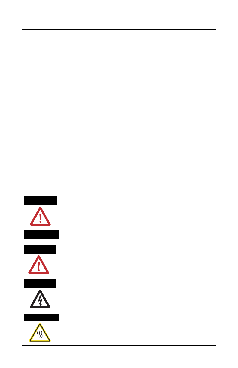
WARNING
IMPORTANT
ATTENTION
SHOCK HAZARD
BURN HAZARD
Identifies information about practices or circumstances that can cause an explosion in
a hazardous environment, which may lead to personal injury or death, property
damage, or economic loss.
Identifies information that is critical for successful application and understanding of
the product.
Identifies information about practices or circumstances that can lead to personal injury
or death, property damage, or economic loss. Attentions help you identify a hazard,
avoid a hazard and recognize the consequences.
Labels may be located on or inside the equipment (e.g., drive or motor) to alert people
that dangerous voltage may be present.
Labels may be located on or inside the equipment (e.g., drive or motor) to alert people
that surfaces may be dangerous temperatures.
Publication 1414-IN006A-EN-P - October 2005
Page 3

Preparation
Electronic to Pneumatic Transducer 3
ATTENTION
(1) Use the filter for the Electronic to Pneumatic Transducer to filter the air supply (catalog number 1414-CAZZZPZZZZ).
Disconnect the power supply before installation.
• Do not exceed the ratings of the device.
• Make all connections in accordance with the wiring diagram
and electrical codes.
• Particles in the air supply larger than 0.03 microns may
adversely affect the reliability and life of the transducer. An
in-line air filter
the main air supply and the main air port of the device.
• A refrigerated air dryer, particulate filter, and coalescing filter
should provide a quality air supply.
• Compressor oil must be non-paraffin mineral base or naphtha
base. Synthetic base oils will destroy pneumatic controls and
void the warranty.
• Do not locate the unit in areas subject to incidental contact,
vibration, severe mechanical shock, excessive moisture, or
corrosive fumes.
• The transducers must be mounted within 5° of the upright
position. See the "UP" arrow on the PCB or label.
(1)
is recommended for installation between
About the Electronic to Pneumatic Transducer
The Electronic to Pneumatic transducer provides a linear 3 to 15 psi output in
response to a 4 to 20mA. It is available in an open style for commercial applications
and in an ABS enclosure for light-industrial applications.
Install the Electronic to Pneumatic Transducer
1. Select the mounting location and mount the device with the ‘UP’ arrow
pointing up using two screws through the base of the snap track or
enclosure.
The printed circuit board may be removed from the snap track for easier
installation. Ensure that the screw heads do not contact the circuit board.
2. Make all necessary electrical connections as per the wiring examples.
Publication 1414-IN006A-EN-P - October 2005
Page 4

4 Electronic to Pneumatic Transducer
The transducer is jumper selectable. The factory default setting is 2-wire,
loop powered 4 to 20 mA device requiring a 4 to 20 mA signal connected to
the INPUT and COM terminals. The unit may also be configured for 3-wire,
0 to 10V dc operation by carefully changing the location of the jumper.
Three-wire operation requires a 24 to 30V ac or DC supply connected to
PWR and COM terminals in addition to the 0 to 10V dc signal applied to the
INPUT terminal.
3. Connect the pneumatic lines to the unit, ensuring that the main air supply is
connected to the black tube and the branch line is connected to the clear
tube.
The main and branch lines are also labeled on the end of the valve with a
‘M’ and a ‘B’.
4. The device may be tested by applying the input ZERO signal (either 4 mA or
0V dc as applicable) and checking the output for a pressure of 3 psig (21
(1)
.
kPa)
Adjust the input for the SPAN signal, 20 mA and check the output for a
pressure of 15 psig (103 kPa). The device is factory calibrated for these
ranges and should not be readjusted in the field.
5. If the unit does not perform as indicated in step 4, then verify all applicable
electrical signals (4 mA, 20 mA; or 10V and the power supply) using a
multimeter.
Also verify that the input air supply is 20 to 30 psig (138 to 207 kPa) and that
the unit is properly mounted and that all wiring is per the wiring examples.
(1) Use the gauge for the Electronic to Pneumatic Transducer to measure pressure (catalog number 1414-CADZZZZFZZ).
Publication 1414-IN006A-EN-P - October 2005
Page 5

Electronic to Pneumatic Transducer 5
Wire/Connect the Electronic to Pneumatic Transducer
PWR – 24 to 30 Vac/dc (0 to 10V dc only)
COM – POWER/SIGNAL COMMON
INPUT – 0-10Vdc OR 4-20mA
Loop power supply
- 24 VDC +
Analog Current /
Voltage Output
ANL VDC+
ANL OUT 0 +
ANL COM
Electronic to Pneumatic
Tranducer
PWR only used with 0-10
VDC input selected
PW R
COM
INPUT
Publication 1414-IN006A-EN-P - October 2005
Page 6

6 Electronic to Pneumatic Transducer
Specifications
Electronic to Pneumatic Transducer Specifications
Specification Value
Input Signal 4…20mA, 0…10V dc jumper selectable
Input Impedance 4…20mA input, 400 Ω minimum, 550 Ω maximum
Power Supply 4…20mA input, Loop powered; 1.0 Watt maximum
Air Supply 138 kPa (20 psig) nominal, 207 kPa (30 psig) maximum Clean, dry, oil-free
Air Consumption 5.66 ml/s (0.012 scfm) @ 138 kPa (20 psig) supply, maximum
Output Air Capacity 141 ml/s (515 scim) maximum @ 138 kPa (20 psig) supply
Air Connections Male barbed fittings for flexible 1/4” OD pneumatic tubing
Wiring Connections Screw terminals for 14 … 22 AWG wire
Output Signal 21…103 kPa (3-15 psig) nominal, direct acting
Manufacturing Process ISO 9002 certified
Linearity ±1% of span
Hysteresis ±1% of span
Adjustments Zero and span potentiometers
Operating Temperature 0°C … 60°C (32°F … 140°F)
Operating Humidity 5…95% RH, non-condensing
Dimensions H x W x D (Snap-Track
model)
Dimensions H x W x D ABS model) 116mm x 84mm x 53mm (4.55” x 3.3” x 2.1”)
air required.
83mm x 70mm x 50mm (3.25” x 2.75” x 2”)
Publication 1414-IN006A-EN-P - October 2005
Page 7

Electronic to Pneumatic Transducer 7
Publication 1414-IN006A-EN-P - October 2005
Page 8

All other trademarks are the property of their respective holders, and are hereby acknowledged.
Publication 1414-IN006A-EN-P - October 2005 PN 40055-236-01(1)
Supersedes Publication XXXX-X.X.X - Month Year Copyright © 2005 Rockwell Automation, Inc. A ll rights reserved. Printed in t he U.S.A.
 Loading...