


TUBE-DRIVEN PROGRAMMABLE 24-BIT DSP GUITAR AMPLIFIER
User's Manual
May be covered by one or more of the following: U.S. Patents #4538297, 4647876, 4696044, 4745309, 4881047, 4893099, 5124657,
5263091, 5268527, 5319713, 5333201, 5402498, 5493617 and 5638452. Other patents pending. Foreign patents pending.
PRECAUTIONS
Note: IT IS VERY IMPORTANT THAT YOU READ THIS SECTION TO PROVIDE YEARS OF
TROUBLE FREE USE. THIS UNIT REQUIRES CAREFUL HANDLING.
• All warnings on this equipment and in the operating instructions should be adhered to and
all operating instructions should be followed.
• Do not use this equipment near water. Care should be taken so that objects do not fall and
liquids are not spilled into the unit through any openings.
• The power cord should be unplugged from the outlet when left unused for a long period of
time.
DO NOT ATTEMPT TO SERVICE THIS EQUIPMENT. THIS EQUIPMENT SHOULD BE SERVICED BY QUALIFIED PERSONNEL ONLY. DO NOT MAKE ANY INTERNAL ADJUSTMENTS OR ADDITIONS TO THIS EQUIPMENT AT ANY TIME. DO NOT TAMPER WITH
INTERNAL ELECTRONIC COMPONENTS AT ANY TIME. FAILURE TO FOLLOW THESE
INSTRUCTIONS MAY VOID THE WARRANTY OF THIS EQUIPMENT, AS WELL AS CAUSING
SHOCK HAZARD.
OPERATING TEMPERATURE
Do not expose this unit to excessive heat. This unit is designed to operate between 32° F and 104° F (0° C
and 40° C). This unit may not function properly under extreme temperatures.
Your Taboo™ Twin has been tested and complies with the following Standards and Directives as set forth by the European Union:
Council Directive(s): 89/336/EEC Electromagnetic Compatibility
Standard(s): EN55013, EN50082-1
This means that this product has been designed to meet stringent guidelines on how much
RF energy it can emit, and that it should be immune from other sources of interference
when properly used. Improper use of this equipment could result in increased RF emissions, which may or may not interfere with other electronic products.
T o insure against this possibility , always use good shielded cables for all audio input and
output connections. Also, bundle audio cables separately from the AC power cables. These
steps will help insure compliance with the Directive(s).
For more information about other Rocktron products, please see your local dealer or one of
our importers closest to you (listed on the enclosed warranty sheet).
Copyright ©1997 Rocktron Corporation.
All rights reserved.

Contents
1. Introduction .................................................................................................................................. 1
2. Quick Setup .................................................................................................................................. 3
3. Front Panel ................................................................................................................................... 4
4. Rear Panel .................................................................................................................................... 8
5. Connections ............................................................................................................................... 12
Connecting a guitar to the Taboo Twin .................................................................................................. 12
Using the Taboo Twin's Direct Outputs with a mixing console .............................................................. 13
Using the Effects Loop .......................................................................................................................... 14
Using the Taboo Twin with a powered cabinet for wide stereo separation ............................................. 15
Using the Taboo Twin with a powered cabinet in a stacked configuration ............................................. 17
6. General Operating Format ......................................................................................................... 19
Taboo Twin Presets .............................................................................................................................. 19
Changing the Preset Sounds ................................................................................................................. 19
Menu and Instant Access Editing Modes .............................................................................................. 20
Taboo Twin Functions and Parameter Descriptions .............................................................................. 22
GLOBAL Function ................................................................................................................................. 23
MIXER Function .................................................................................................................................... 24
HIGH GAIN Function ............................................................................................................................. 25
LOW GAIN Function .............................................................................................................................. 26
HUSH® Function ................................................................................................................................... 27
PRE EQ (EXPERT) Function ................................................................................................................ 28
POST EQ (EXPERT) Function .............................................................................................................. 29
COMPRESSOR Function ...................................................................................................................... 30
WAH-WAH Function .............................................................................................................................. 31
PHASER Function ................................................................................................................................. 32
FLANGER Function ............................................................................................................................... 33
TREMOLO Function .............................................................................................................................. 34
PITCH SHIFT Function ......................................................................................................................... 35
CHORUS Function ................................................................................................................................ 37
DELAY Function .................................................................................................................................... 38
REVERB Function ................................................................................................................................. 40
7. Operating the Taboo Twin ......................................................................................................... 41
Selecting a preset ................................................................................................................................. 41
Changing preset parameters not provided by Instant Access controls ..................................................42
Storing changed preset parameters ....................................................................................................... 43
Editing a preset title .............................................................................................................................. 45
Controller Assignments ......................................................................................................................... 47
Tap Delay .............................................................................................................................................. 50
Program Changes .................................................................................................................................. 53
MIDI Channels ....................................................................................................................................... 55
MIDI Dump/Load ................................................................................................................................... 57
Factory Restore ..................................................................................................................................... 63
Restoring a single factory preset: ..........................................................................................63
Restoring a single factory preset: ..........................................................................................65
Restoring the T aboo T win controller assignments: .................................................................66
Using the Taboo Twin with a Rocktron All Access® in REMOTE mode ............................................... 67
9. Appendix .................................................................................................................................... 70
ERROR MESSAGES ............................................................................................................................ 70
MIDI IMPLEMENTATION ..................................................................................................................... 71
TECHNICAL DATA ................................................................................................................................ 72

1. Introduction
Congratulations on your purchase of the Rocktron
The T aboo Twin is a 24-bit DSP professional tube guitar amplifier providing 12 unparalleled effect algorithms and superb sound quality never before heard from a digital tube guitar
amp. Complete programmability and full MIDI implementation are coupled with a user friendly
operating format to ensure that designing unique and useful preset sounds is as simple as
possible.
In addition, the T aboo Twin also features:
• High-quality Digital Effects, including:
- Reverb - Phasing - T remolo - Flanging
- Pitch Shifting - Compression - Chorus - Delay
• Full parametric Pre and Post EQ gives the user complete EQ
control over each preset.
• HUSH® Noise Reduction reduces noise while playing and provides complete silence when not.
• "Variac" Simulation, like a conventional Variac, adjusts the level
at which the preamp begins to distort. This provides more gain in
high-gain applications, and allows for full-bodied cleaner presets
which just begin to distort when the strings are attacked harder .
T aboo™ Twin
!
• Internal Wah-Wah allows the player to use an expression pedal
for Wah-Wah effects instead of running long audio cables out to a
conventional Wah-Wah pedal.
• XLR Outputs for direct mixer input.
• Advanced Speaker Simulation on the XLR outputs provides a
realistic approximation of a miked speaker cabinet at line-level for
direct mixer input or headphone listening.
This manual will detail the various features and functions of the T aboo Twin. After read-
ing it, please keep it for future reference.
1

OPERATING PRECAUTIONS
NOTE: IT IS VERY IMPOR TANT THA T YOU READ THIS SECTION T O PROVIDE
YEARS OF TROUBLE FREE USE. THIS UNIT REQUIRES CAREFUL HANDLING.
All warnings on this equipment and in the operating instructions should be adhered
to and all operating instructions should be followed.
Do not use this equipment near water . Care should be taken so that objects do not
fall and liquids are not spilled into the unit through any openings.
The power cord should be unplugged from the outlet when left unused for a long
period of time.
DO NOT A TTEMPT TO SER VICE THIS EQUIPMENT . THIS EQUIPMENT SHOULD
BE SERVICED BY QUALIFIED PERSONNEL ONL Y. DO NOT MAKE ANY INTERNAL ADJUSTMENTS OR ADDITIONS TO THIS EQUIPMENT A T ANY TIME. DO
NOT T AMPER WITH INTERNAL ELECTRONIC COMPONENTS A T ANY TIME.
FAILURE T O FOLLOW THESE INSTRUCTIONS MA Y VOID THE WARRANTY OF
THIS EQUIPMENT , AS WELL AS CAUSING SHOCK HAZARD.
OPERATING TEMPERATURE
Do not expose this unit to excessive heat. This unit is designed to operate between
32° F and 104° F (0° C and 40° C). This unit may not function properly under
extreme temperatures.
2
2. Quick Setup
SELECTING A PRESET
1 Turn the PRESET control to the desired preset. It will be recalled
automatically.
QUICKLY CHANGING PRESET SOUNDS
1 Make sure the Menu button is not lit. (This allows for T aboo Twin
parameters to be edited in Instant Access mode.)
2 Use the controls in the Instant Access control group, as well as those
labeled E
preset sounds.
FFECT LEVEL, D ELAY LEVEL and REVERB LEVEL to quickly edit
3 Any
4 Any combination of these effects may be selected at any time.
one of these effects may be selected at any time.
3
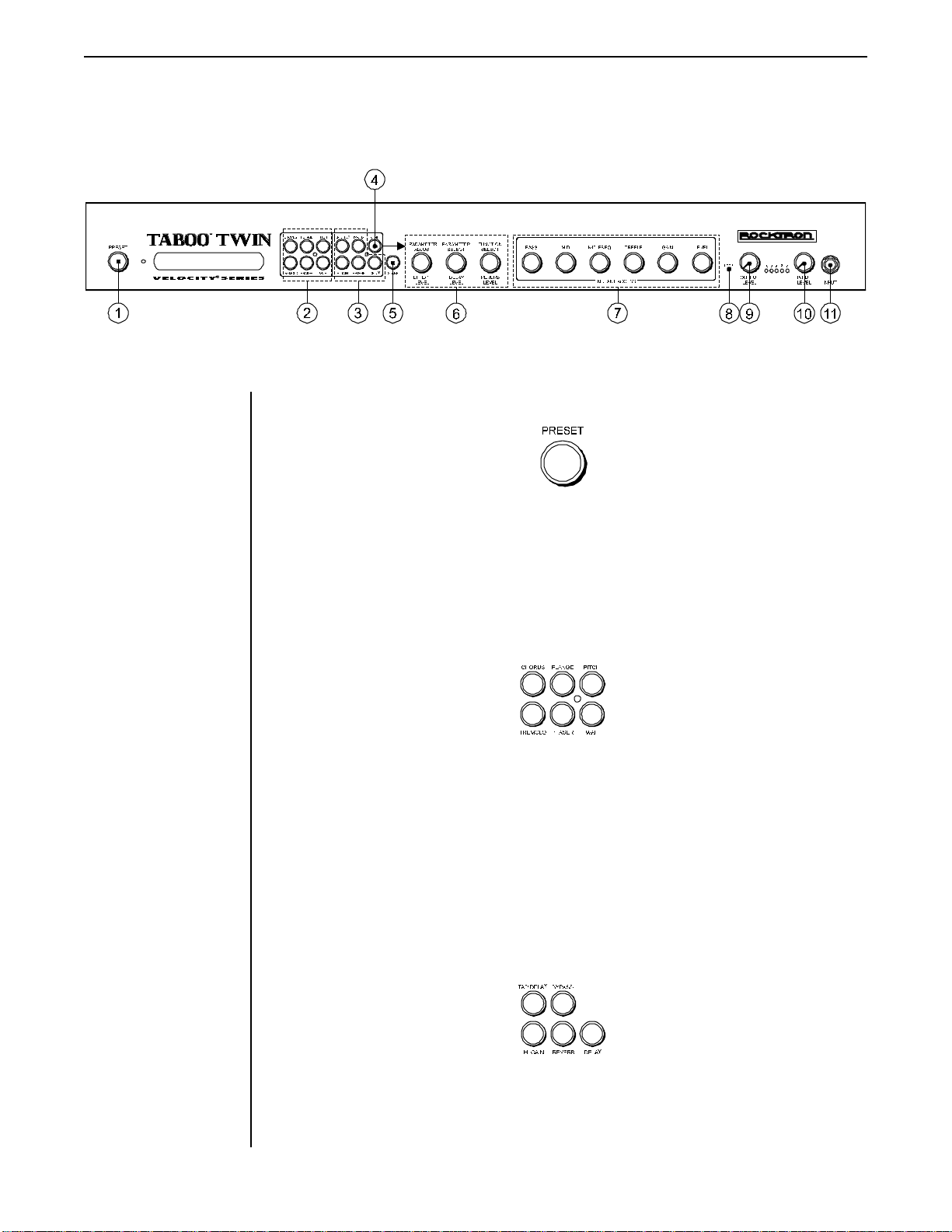
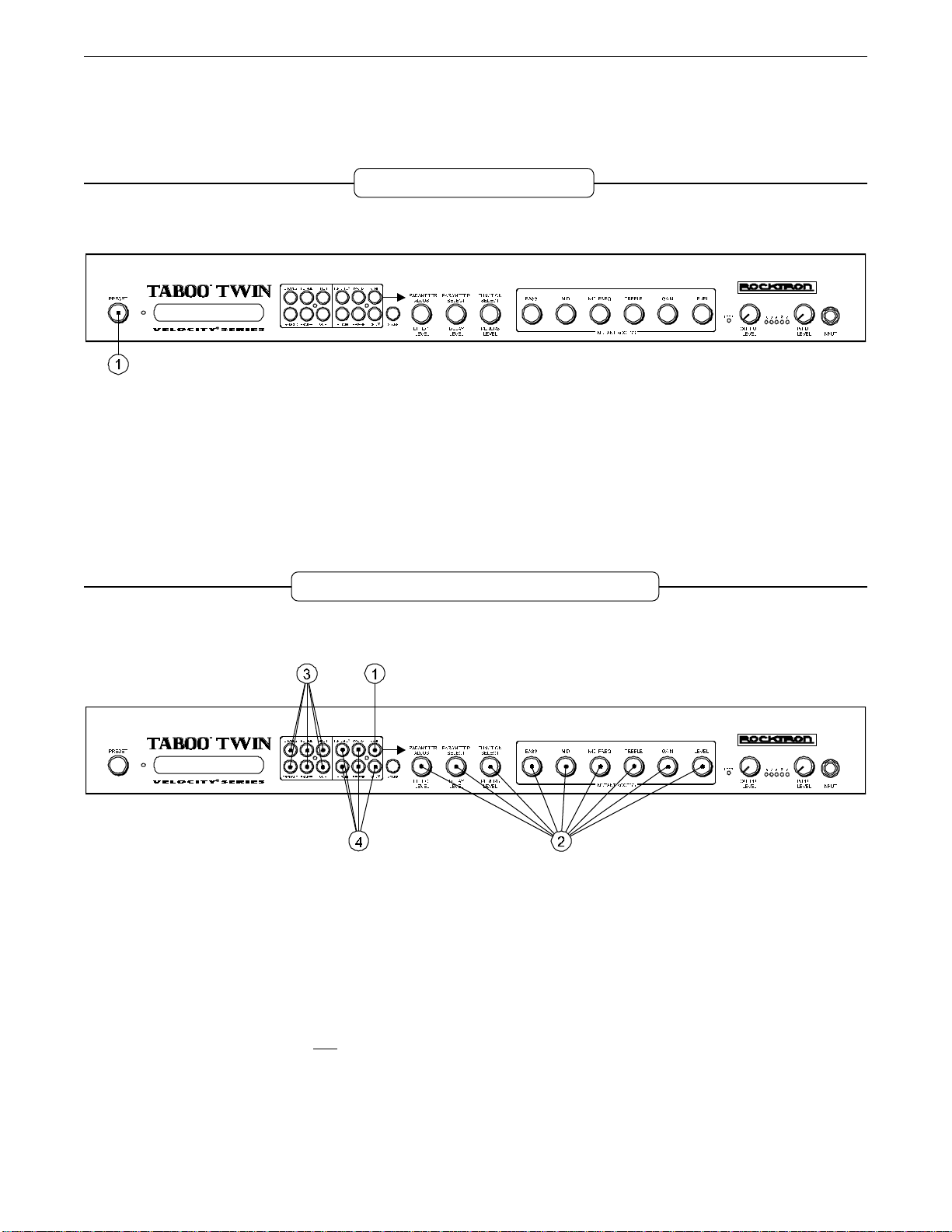
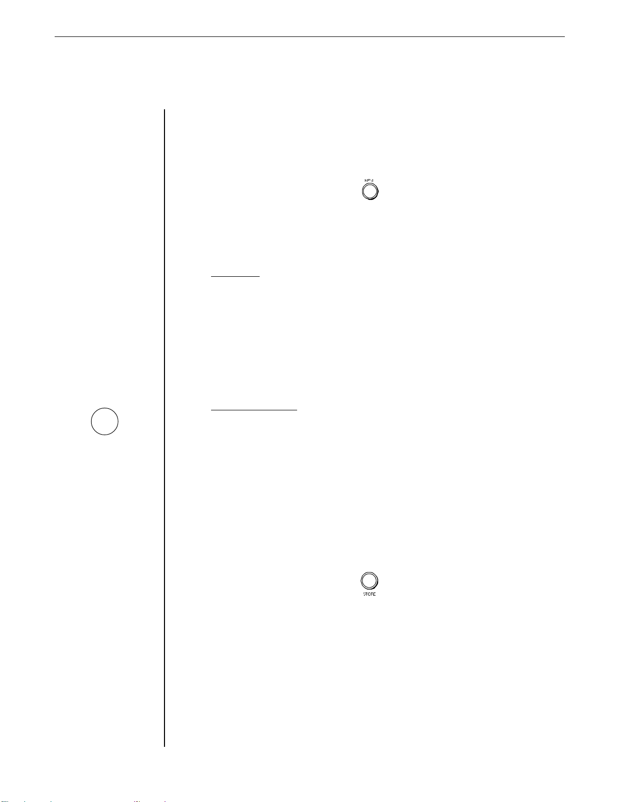
3. Front Panel
1PRESET control
This control is used to scroll through the successive Taboo Twin presets. Each preset is
automatically recalled when displayed.
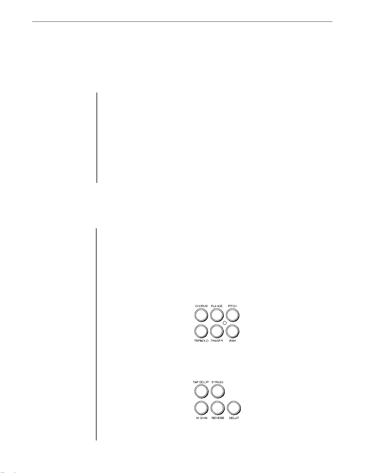
2 Effects group (one selection only)
This group of buttons provides in/out switching to six of the Taboo Twin's effects
(Chorus, Flange, Pitch, Tremolo, Phaser and Wah).
Note that this group of effects is mutually-exclusive, meaning that only one of the effects
in this group can be switched in at any given time. Switching in one of these effects
when another in the group is already active will automatically switch out the effect that
was previously selected.
3 Effects group (multiple selections allowed)
This group of buttons provides in/out switching to the remaining Taboo Twin effects
(T ap Delay, High Gain, Reverb, Delay, Bypass).
4
G
The EFFECT LEVEL control
provides instant access to
the level parameter of the
effect selected in the
mutually-exclusive group
of six effects (see item 2).
Note that any of the functions within this group can be switched in or out of the signal
path independent of the others (i.e., multiple selections can be made).
4MENU button
The MENU button determines the current editing mode of the Taboo Twin. The Taboo
Twin provides two modes for editing preset sounds — Menu mode and Instant Access
mode.
Menu mode
Menu mode allows access to all of the functions and parameters that the Taboo Twin
provides. Since this mode allows access to more parameters than Instant Access mode,
it provides more control over the overall sound of a preset.
When this switch is lit, Menu mode is active and all functions and parameters can be
edited via the F UNCTION SELECT, PARAMETER SELECT and PARAMETER ADJUST controls. See
Section 6, General Operating Format, and Section 7, Operating the Taboo Twin, for
detailed descriptions of these controls. Note that all controls included in the front panel
Instant Access group are still enabled when Menu mode is active.
Instant Access mode
When the MENU switch is not lit, Instant Access mode is the active editing mode. In
this mode, the controls located in the front panel Instant Access group provide immediate access to the most significant level parameters of the current preset — thus
allowing the user to avoid scrolling through numerous menus and parameters to edit a
desired level. These controls include B ASS, M ID, MID-F REQ, TREBLE, GAIN and LEVEL .
In addition, the FUNCTION SELECT, PARAMETER SELECT and PARAMETER ADJUST controls
provide secondary functions in this mode to provide direct access to additional level
parameters. These are R EVERB LEVEL, DELAY LEVEL, and E FFECT LEVEL, respectively .
5STORE button
The STORE button is used to save any changes made to a preset into the Taboo Twin
memory. (Changing and saving presets is discussed further in Section 7, "Operating
the Taboo Twin" .)
5
G
When a parameter value
has been altered from its
original value, the S
button will light to indicate
that the preset has
changed. The S
will then stay lit until either
the altered preset is stored,
a new preset is selected, or
all parameters for the
current preset are returned
to their original values.
TORE
TORE button
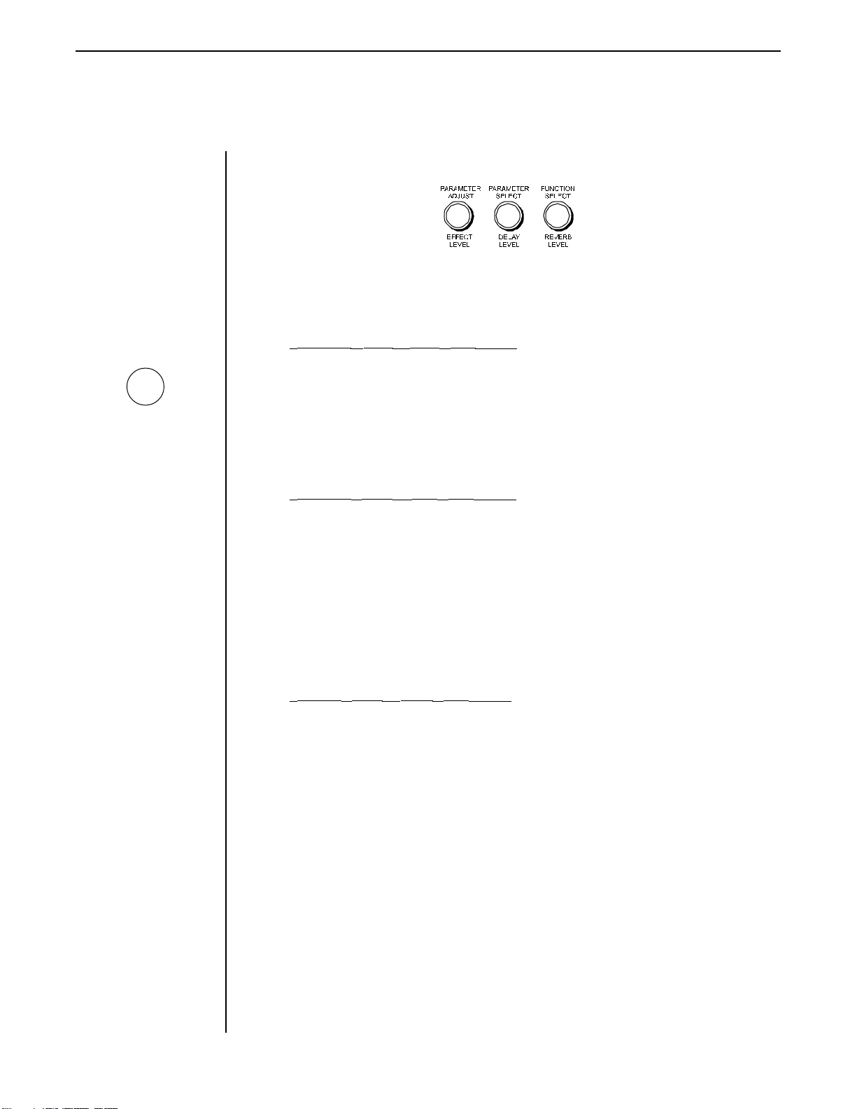
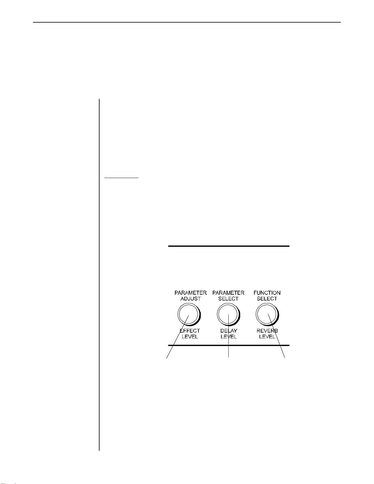
6 Dual function controls
The function of each of these controls is dependent upon the current status of the
MENU button. The upper label denotes the function of the control when Menu mode is
active, while the lower label denotes the function of the control in Instant Access mode.
PARAMETER ADJUST / EFFECT LEVEL control
When Menu mode is active (i.e., the MENU button is lit), this control is used to adjust a
displayed parameter value.
When the active edit mode is Instant Access (i.e., the MENU button is not lit), this
control is used to determine the level of the chorus, phaser, tremolo, wah, flange or pitch
effect (whichever is currently active).
PARAMETER SELECT / DELAY LEVEL control
When the MENU button is lit, this control is used to scroll through the available
parameters under the current function heading.
When in the Title Edit function, this control is used to scroll through the available
character locations to be edited.
When the MENU button is not lit, this control is used to determine the overall delay
level for the current preset. Turning this control will automatically display the Delay
Level parameter.
FUNCTION SELECT / REVERB LEVEL control
In Menu mode, this control is used to access each of the primary functions of the
Taboo Twin. These functions include:
Global Pre EQ Phaser Delay Footswitch
Mixer Post EQ Flanger Reverb Program Changes
High Gain Compressor Tremolo MIDI Channels Controller Assign
Low Gain Pitch Shift Title Edit MIDI Dump/Load HUSH
Wah-Wah Chorus Factory Restore
Once a function has been selected, the parameters for the function are accessible via
the PARAMETER SELECT control.
When the MENU button is not lit, this control is used to determine the overall reverb
level for the current preset. Turning this control will automatically display the Reverb
Level parameter.
6
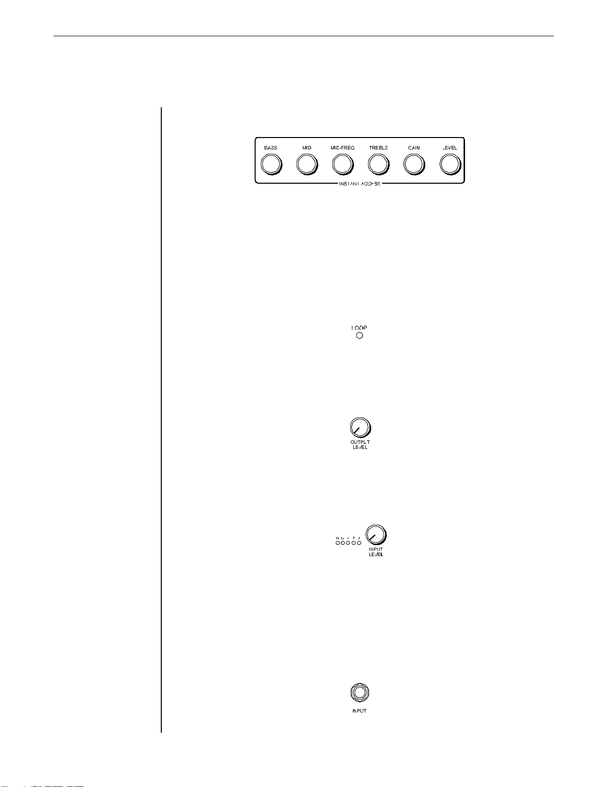
7 Instant Access control group
When the Taboo Twin is in Instant Access mode (i.e. MENU button not lit), these
controls provide instant access to selected post-distortion parameters of the current
preset. These include:
Bass Level Mid Level Mid-Freq Treble Level Gain Level Level Level
When the MENU button is lit, these controls are still enabled.
8LOOP L.E.D.
When lit, indicates that the effects loop is currently active.
9OUTPUT LEVEL control
This control is used to adjust the master output level of the unit.
10 INPUT LEVEL control and meter
The Input Level control adjusts the Taboo Twin's gain to match the signal level applied
to the input of the unit. This gain can be adjusted from -12dB to +12dB.
The Input Level meter provides visual indication of the peak level of the input signal.
For the optimal signal-to-noise ratio, it is best to adjust the input level so that the last
LED (0dB) is rarely lit. This will guard against the possibility of overdriving the unit.
10 INPUT jack
This standard unbalanced ¼" jack provides input to the Taboo Twin.
7
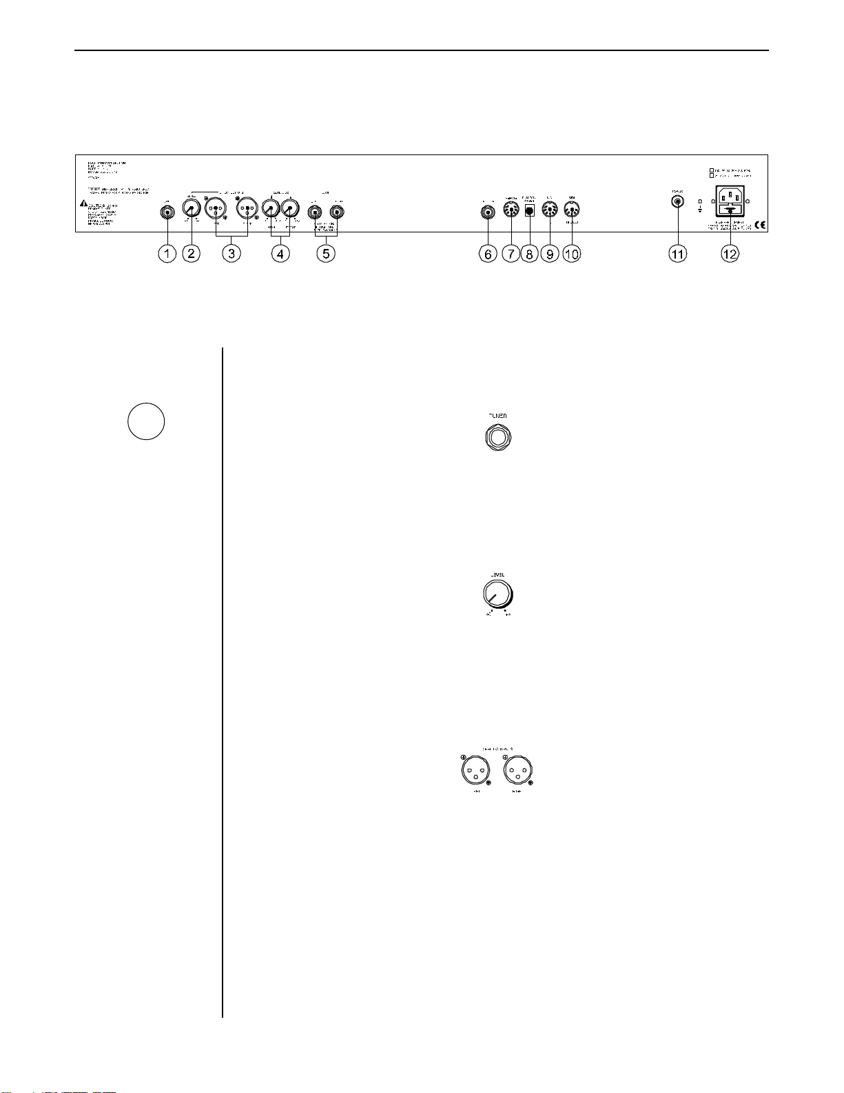
4. Rear Panel
1TUNER jack
G
The signal fed to the rear
panel T
UNER jack is not part
of the signal path. There-
fore, a dead battery or other
malfunction in the tuner will
not affect the sound of the
amplifier .
2 Direct Output LEVEL control
This ¼" mono jack provides a signal tapped from the front panel input that can be fed to
a guitar tuner.
This control determines the output level of the direct signal fed through the adjacent
LEFT and RIGHT Direct Outputs XLR connectors.
3LEFT and R IGHT Direct Outputs connectors
These connectors provide left and right signals that can be fed directly into a mixing
console or recording device. Note that both of these outputs feature speaker simulation
circuitry.
8
!
It is important to note that
the effects loop
used in a stereo configura-
tion (i.e., only stereo RTS
connections can be made to
the rear panel S
ETURN jacks.
R
must be
END and
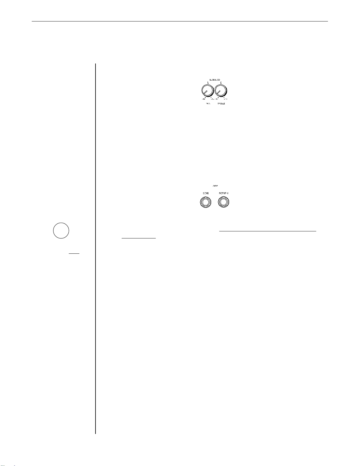
4 Global EQ BASS and TREBLE level controls
The Global EQ controls provide instant adjustment of the bass and treble frequencies of
the Taboo Twin across all presets. This feature is useful when a particular venue
provides acoustic characteristics which would require readjustment of the EQ parameters of all the presets. Rather than tediously changing the relevent parameters within
each preset, the Global EQ controls allow for quickly increasing or decreasing the bass
and treble for all presets when necessary.
5 Effects Loop SEND and RETURN jacks
The effects loop is provided to allow for a chain of external stereo (L/R) effects devices
to be inserted in the signal path. Note that the effects loop must be used in a stereo
configuration. This means that only stereo RTS connections can be made to the rear
panel SEND and RETURN jacks. The connection of ¼" mono plugs to these jacks will
cause improper operation when the effects loop is switched in, and may damage the
unit. Improper use may also void the warranty.
The ¼" stereo RTS SEND jack provides left and right post-distortion outputs to the left
and right inputs of the first device in the effects chain, while the ¼" stereo RTS RETURN
jack accepts the left and right outputs from the last device in the effects chain.
Each of the jacks are configured as follows:
Tip (T) = Right
Ring (R) = Left
Sleeve (S) = GND
The effects loop can be activated or bypassed via the Loop I/O parameter.
9
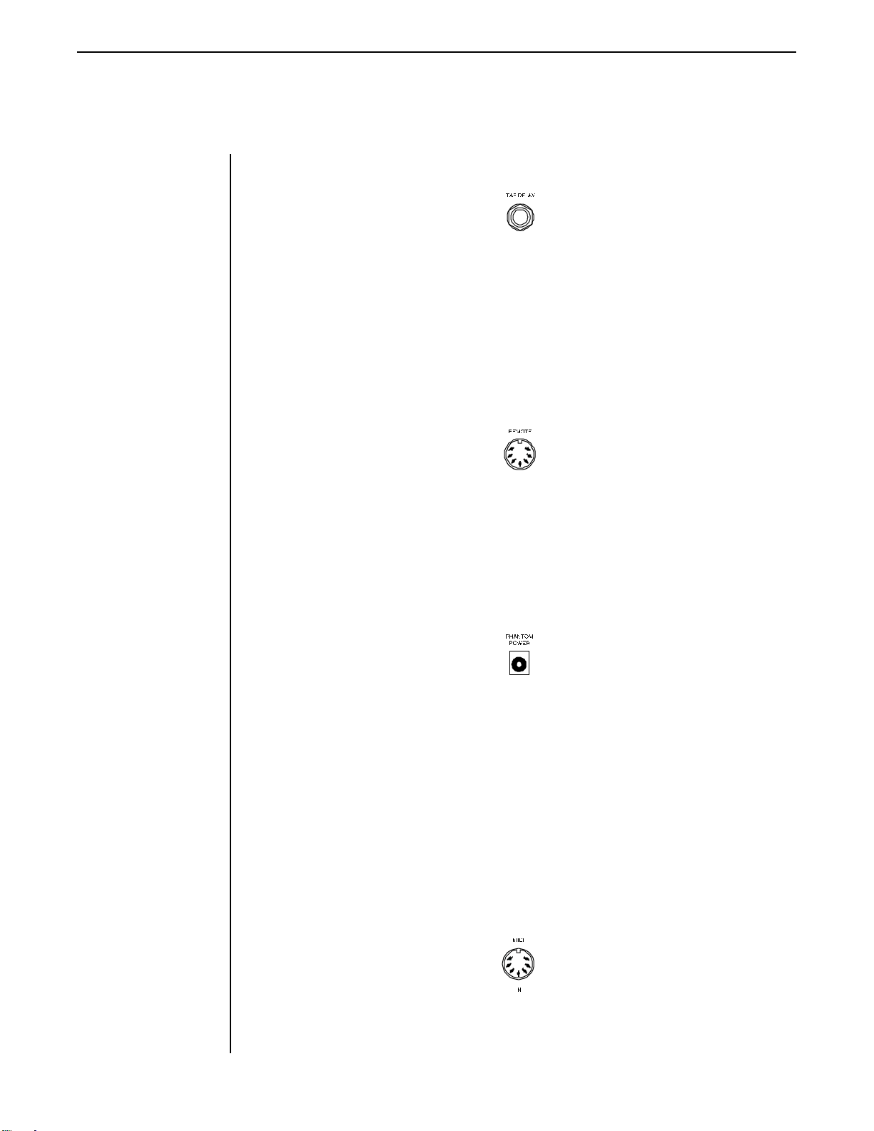
6TAP DELAY jack
This ¼" mono jack allows for the connection of a momentary footswitch to control the
Tap Delay feature of the Taboo Twin. The Tap Delay function allows for the current
delay time to be set (or reset) by tapping the footswitch connected to the TAP DELAY
jack. The new delay time will be based on the length of time between two taps.
The Tap Delay function is discussed further in Chapter 7, Operating the Taboo Twin.
7REMOTE jack
This 7-pin DIN connector is provided for the connection of a Rocktron All Access
MIDI footswitch, which can be configured to act as a dedicated remote footswitch for
the Taboo Twin. This feature provides access to Taboo Twin functions and parameters
via the remote footswitch.
8PHANTOM POWER jack
This 2.5mm PIN jack provides the ability to power Rocktron MIDI foot controller from a
7-pin MIDI cable which connects from the MIDI Mate to the MIDI IN jack on the rear
panel of the Taboo Twin, thus eliminating the need to find an AC outlet near where the
footpedal would be placed during a performance—or the need to run an extension cord
out to the foot controller.
Instead of inserting the adaptor into the Rocktron foot controller's POWER jack, plug it
into the P HANTOM POWER jack on the Taboo T win. This will power the foot controller
through pins 6 and 7 of the MIDI cable connecting the two units. A 7-pin MIDI cable
must be used for this feature and is available through your Rocktron dealer.
®
10
9 MIDI IN jack
This 7-pin DIN connector receives MIDI information from the device which is
transmitting the MIDI commands for the T aboo T win to execute.
G
Inherently in MIDI there is a
limit to the number of
devices which can be
chained together (series
connected). With more than
three devices, a slight
distortion of the MIDI signal
can occur (due to signal
degradation) which can
cause an error in MIDI
signal transmission. Should
this problem arise, a MIDI
box can be used which
connects directly to the
MIDI device which transmits
MIDI information and has
multiple connectors for the
multiple devices receiving
MIDI. MIDI cables should
not exceed 50 feet (15
meters) in length.
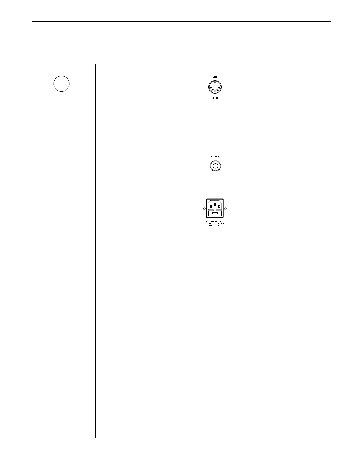
10 MIDI THRU/OUT jack
This standard 5-pin DIN connector passes on the MIDI information that is received at
the MIDI IN jack to other MlDI-compatible devices via a MIDI cable. It also outputs
MIDI data when performing a memory dump.
11 POWER switch
12 POWER INLET module
This module provides a connection for the power cord and also houses the main fuse of
the unit.
11
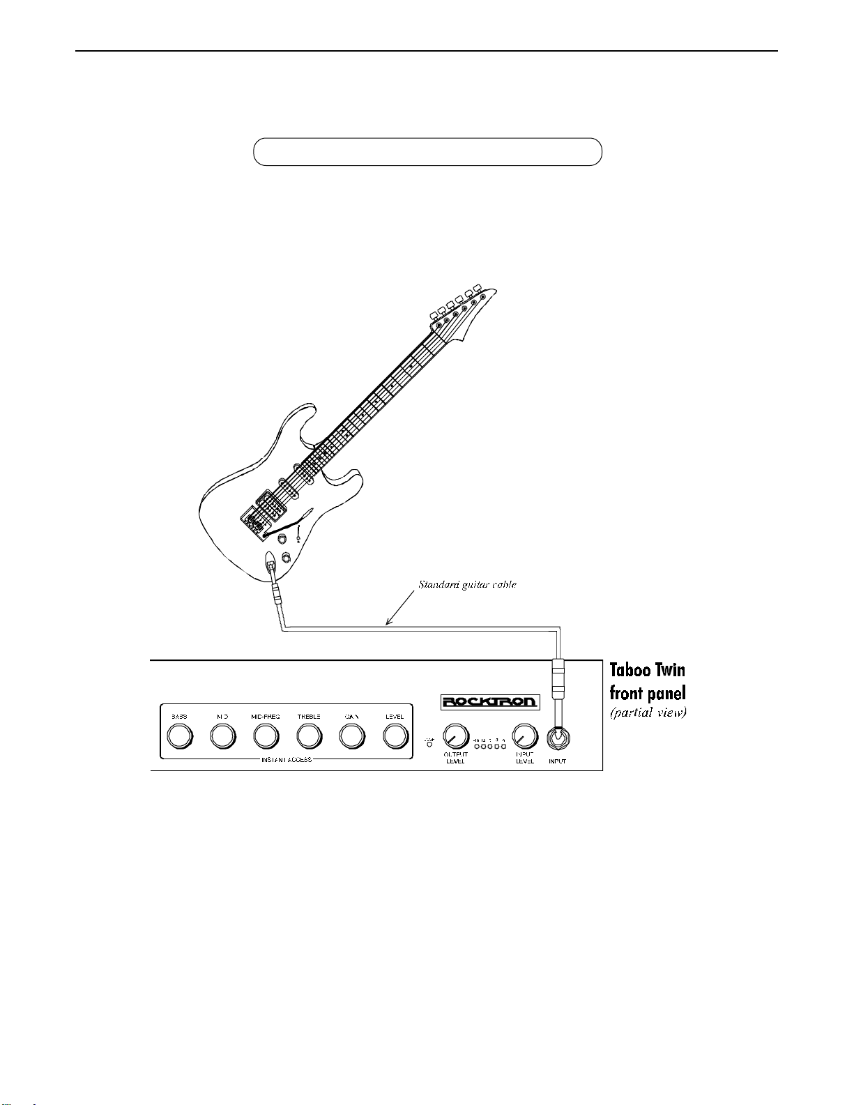
5. Connections
Connecting a guitar to the Taboo Twin
12
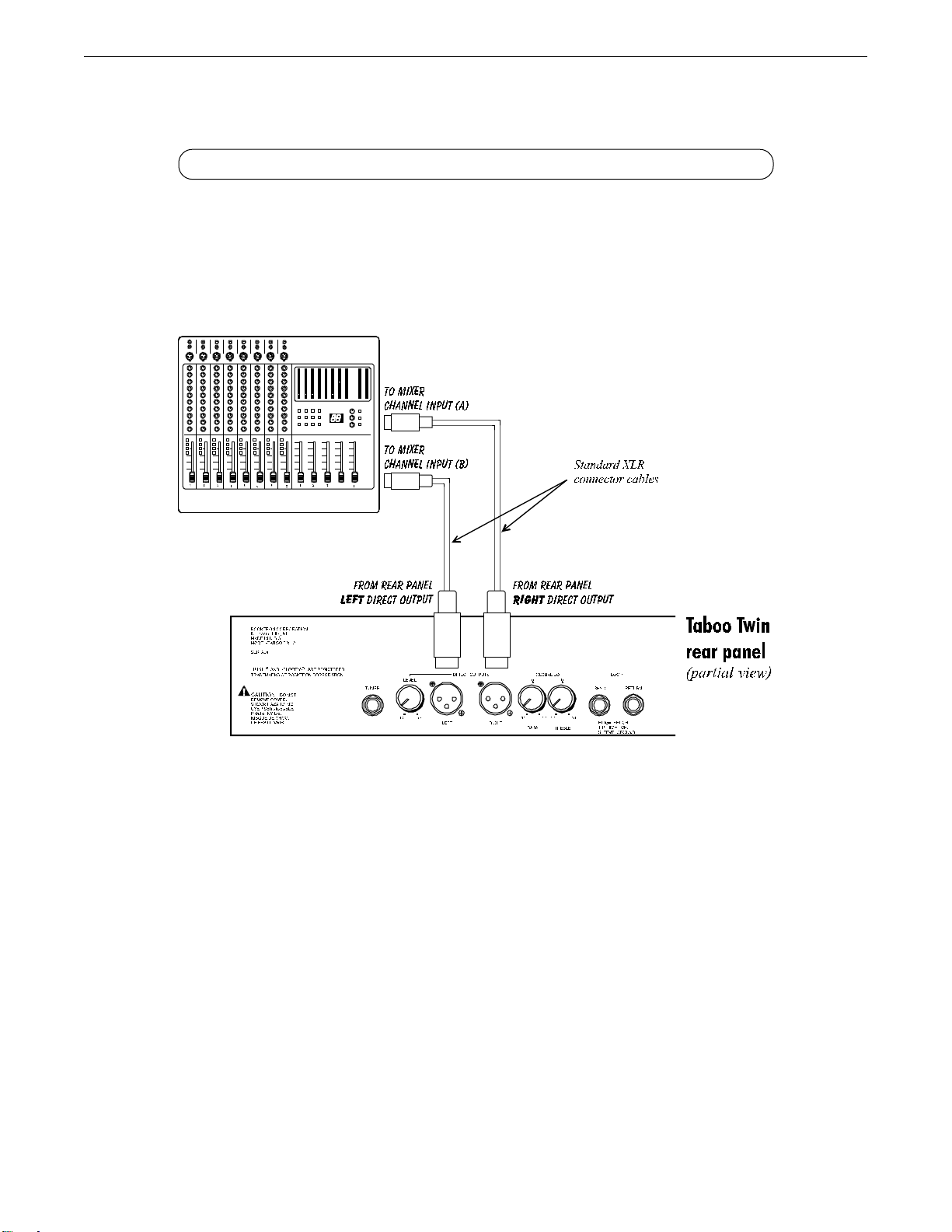
Using the Taboo Twin's Direct Outputs with a mixing console
13
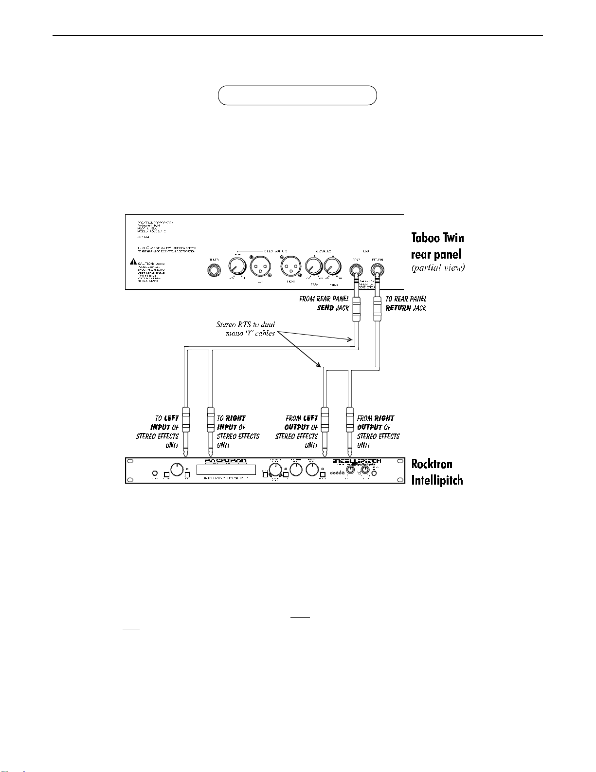
Using the Effects Loop
14
• It is important to note that the effects loop must be used in a stereo configuration (i.e.,
only stereo RTS connections can be made to the rear panel SEND and RETURN jacks.
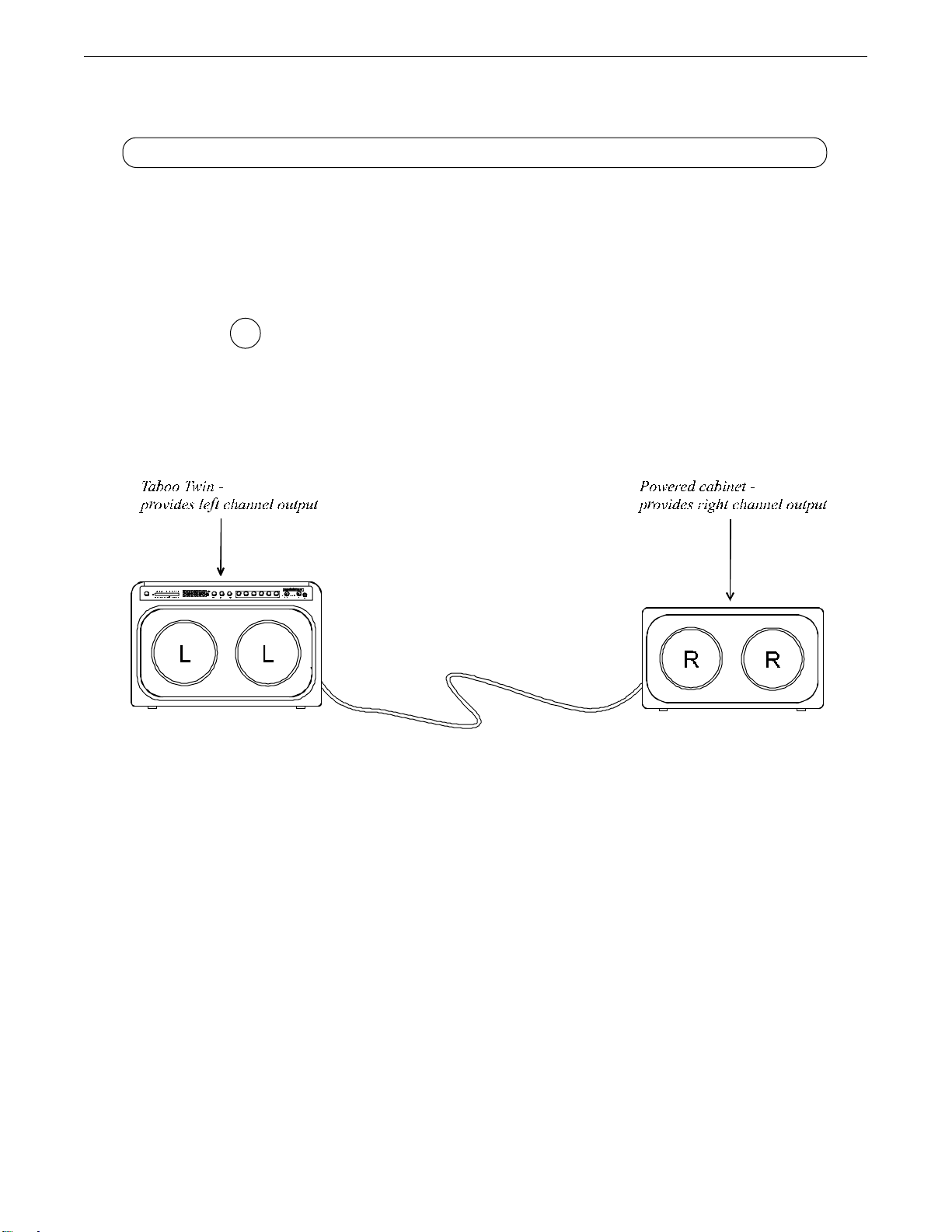
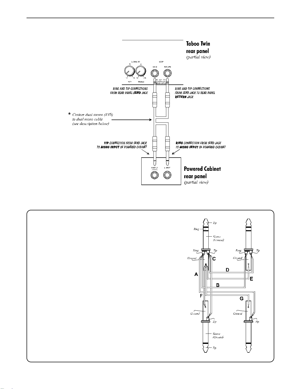
Using the Taboo Twin with a powered cabinet for wide stereo separation
The T aboo T win can be used with a powered speaker cabinet to provide
wide stereo separation. In the configuration shown below , both speakers of
the T aboo T win provide the left channel output, while both speakers of the
powered cabinet provide the right channel output.
To operate in this configuration, the
G
(found in the
The necessary connections between the T aboo T win and powered
cabinet are shown on the following page.
Global
function) must be set to "LEFT".
Output
parameter
* Note that this configuration requires a specially configured cable. The wiring for this
cable is described on the following page.
15
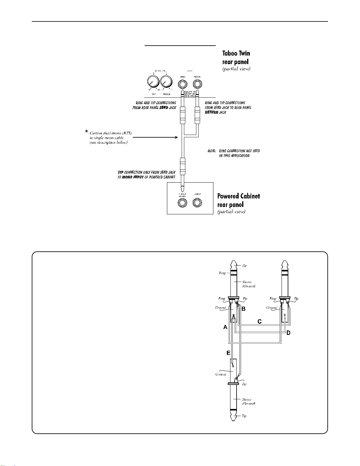
Taboo Twin / Powered Cabinet connections:
Cable wiring required for this configuration:
A Ring of stereo RTS S END plug to Ring of stereo RTS
RETURN plug
B Tip of stereo RTS SEND plug to Tip of mono R INPUT plug
C Tip of stereo RTS S END plug to Tip of stereo RTS RETURN
plug
D Ground of stereo RTS SEND plug to Ground of stereo
RTS RETURN plug
E Ground of stereo RTS SEND plug to Ground of mono R
INPUT plug
16
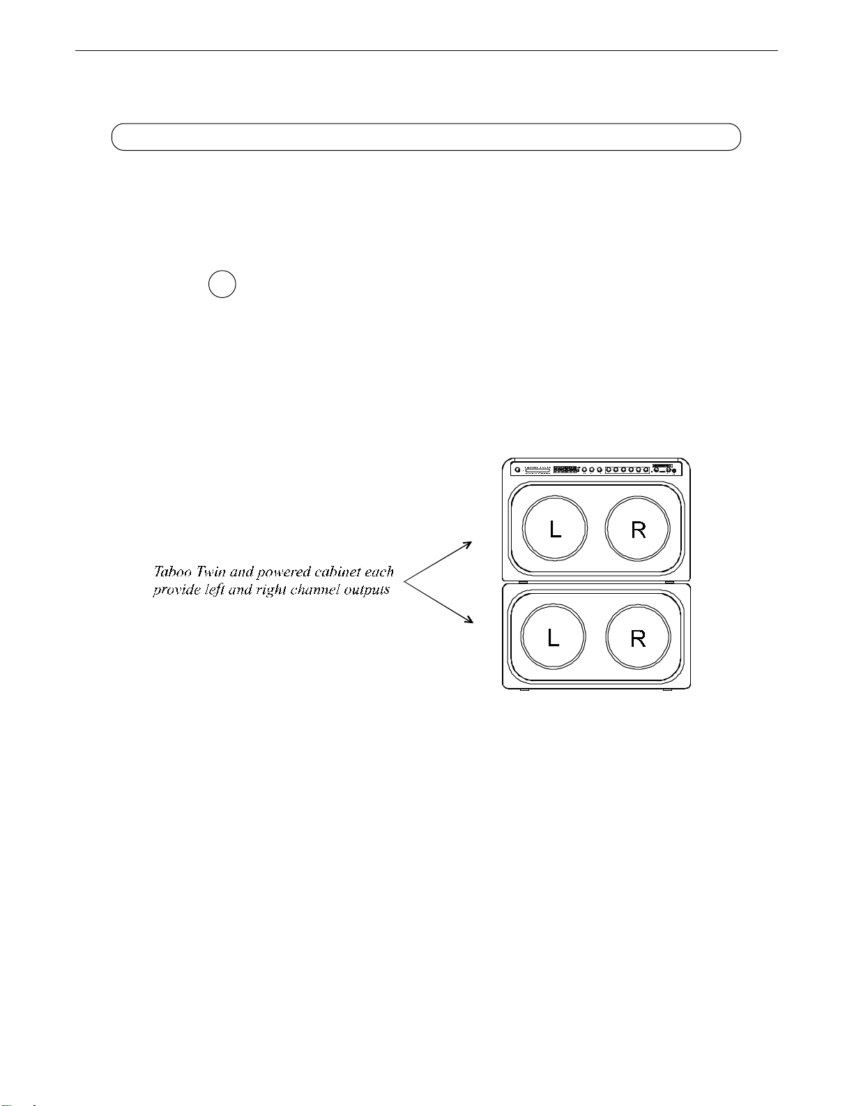
Using the Taboo Twin with a powered cabinet in a stacked configuration
The T aboo T win can also be used with a powered speaker cabinet in a
stacked configuration. In the configuration shown below , the T aboo T win
and powered cabinet each provide left and right channel outputs.
To operate in this configuration, the
G
(found in the
The necessary connections between the T aboo T win and powered
cabinet are shown on the following page.
Global
function) must be set to "STEREO".
Output
parameter
* Note that this configuration requires a specially configured cable, and is described on
the following page.
17
Taboo Twin / Powered Cabinet connections:
Cable wiring required for this configuration:
A Ring of stereo RTS SEND plug to Tip of mono L INPUT
plug.
B Ring of stereo RTS SEND plug to Ring of stereo RTS
RETURN plug
C Tip of stereo RTS SEND plug to Tip of mono R INPUT plug
D Tip of stereo RTS S END plug to Tip of stereo RTS RETURN
plug
E Ground of stereo RTS SEND plug to Ground of stereo
RTS RETURN plug
F Ground of stereo RTS S END plug to Ground of mono R
INPUT plug
G Ground of stereo RTS SEND plug to Ground of mono L
INPUT plug
18
6. General Operating Format
Taboo Twin Presets
The T aboo T win provides 128 stored sounds called
can be called up at any time via the front panel PRESET control, or by a remote MIDI
footswitch.
Each T aboo T win preset is divided up into individual blocks called
"Mixer", "Reverb", etc.). Within each function is a set of
manipulate various aspects of that function. It is the setting of each of the parameters
which determines the overall sound of each Taboo Twin preset.
Each of the T aboo T win's 128 preset locations can be edited, copied over and restored to original factory state as many times as necessary. These tasks, and many
others, are described in detail in section 7,
Changing the Preset Sounds
The sound of each preset is determined by the effects that are selected as well as
the settings of their respective parameters. Effects are selected and deselected by
pressing their relevant buttons on the front panel.
Some effects can be inserted into the audio path regardless of any others that are
currently selected, while others require that some other effect is switched out before
becoming active. For this reason, the effects are grouped into two separate sections on
the front panel, as shown below.
presets
parameters
"Operating the T aboo T win"
. Any of the 128 presets
which allow you to
functions
.
(such as
Only one of the above effects may be selected at any given time...
...while any combination of these effects can be selected.
19
Menu and Instant Access Editing Modes
T o provide widest array of sounds possible, the Taboo Twin provides
many
parameters
for the various effects and functions that the amplifier provides. Occasionally , however , it
is much more quick and convenient to have a set of controls that directly access specific
often-edited parameters immediately, rather than paging through numerous menus,
functions and parameters to find the desired parameter to edit.
For this reason, the T aboo T win provides two modes for editing preset sounds. The
currently active mode is determined by the front panel MENU button.
Menu Mode
In Menu mode (i.e. MENU button lit), the Taboo Twin is set up to allow you to first
access each function (via the FUNCTION SELECT control), then the parameter list for the
selected function (via the P ARAMETER SELECT control) and finally the adjustable value for the
displayed parameter (via the PARAMETER ADJUST control).
20
Step 3:
Turn to alter the value of
the selected parameter.
Step 2:
Turn to select a parameter
within the selected function.
Turn to select a function.
Step 1:
Controls used to access and edit Taboo Twin parameters in Menu mode.

Instant Access Mode
G
Note that all editable EQ
parameters in Instant
Access mode are post-
distortion.
When the MENU switch is
not
lit, the amplifier can be edited in Instant Access mode.
This mode allows for immediate access to nine of the most commonly edited parameters
for any preset:
Level, Effect Level, Delay Level
Bass Level, Mid Level, Mid Frequency, T reble Level, Gain Level, Output
and
Reverb Level
. The first six of these parameters are
immediately accessible via the Instant Access control group on the front panel (shown
below).
Provides instant
access to Bass
Level parameter
access to Mid Level
access to Mid Freq
Provides instant
parameter
Provides instant
parameter
Provides instant
access to Treble
Level parameter
Provides instant
access to Gain
Level parameter
Provides instant
access to Level
parameter
The
Effect Level, Delay Level
and
Reverb Level
parameters are immediately acces-
sible via the PARAMETER ADJUST, PARAMETER SELECT and FUNCTION SELECT controls.
Provides instant access to
Level parameter of currently
active effect (i.e. chorus,
flanger , phaser, pitch shift,
tremolo or wah)
Provides instant access to
Delay Level parameter
Provides instant access to
Reverb Level parameter
21

Taboo Twin Functions and Parameter Descriptions
The remainder of this section will describe each of the effect-based functions and the
adjustable parameters they each provide. Note that the functions and parameters that are
available for a given preset are dependent upon which effects are currently active. Therefore, not all functions and parameters described in this section are available in every
T aboo T win preset.
The remaining functions are utility-based, and are described in Section 7,
the T aboo T win".
"Operating
22

GLOBAL Function
The first function displayed when turning the FUNCTION SELECT control is the Global function. The parameters provided in
this function affect all presets (i.e. the settings stored for these parameters are the same for all presets).
The PARAMETER SELECT control will allow you to access the following Global parameters:
Parameter Description
OUTPUT The OUTPUT parameter determines the output configuration of the Taboo T win. It is important
that this parameter is set correctly
In most situations, this parameter should be set to STEREO. When set to STEREO, one speaker
of the Taboo Twin provides the left channel output, while the other speaker provides the right
channel output.
When MONO is selected, the left and right outputs of the Taboo Twin are summed together,
and the same mono signal is fed through both speakers of the Taboo Twin, as well as each of
the outputs.
When using the Taboo Twin with an additional powered cabinet, it is common to set this
parameter to LEFT. When set to LEFT, both speakers of the T aboo Twin provide only the left
channel output, while the tip connection from the rear panel SEND jack provides the right
channel signal to be fed to the separate powered cabinet (see pages 15-16 for more information).
Note that this configuration requires a specially configured cable.
HUSH The HUSH OFFSET parameter allows you to globally (all presets) adjust the HUSH® Expander
OFFSET Threshold. This means that if this parameter is altered from 0dB to +3dB, the Expander Thresh-
old will be 3dB higher for all presets. This feature can be useful when switching from a quiet
guitar with passive electronics to a noisy guitar with active electronics - as the active guitar
would require a higher Threshold level in all presets.
MUTE The MUTE parameter allows you to mute the output of the Taboo Twin. This feature is espe-
cially useful when changing guitars during a live set. If a Rocktron All Access™ is used in
remote mode with the Taboo Twin, a single All Access button can be configured as a momentary switch which will mute the output when it is held down. (See "Using a T aboo Twin with a
Rocktron All Access in REMOTE mode" in Chapter 7 for more information.)
23

MIXER Function
The next function displayed after turning the FUNCTION SELECT control is the Mixer function. The Mixer function parameters are included in all presets—although the parameter values stored in this function are only for the currently recalled
preset.
This digital mixer allows you to control most signal levels pertaining to each preset’s effect configuration and stores these
levels for each preset.
The PARAMETER SELECT control will allow you to access the following Mixer parameters:
Parameter Description
VOLUME The VOLUME parameter determines the overall signal level of the current preset.
LEFT OUT The LEFT OUT LEVEL parameter allows you alter the level of the left channel
LVL output of the current preset independent of the right channel.
RIGHT OUT The RIGHT OUT LEVEL parameter allows you alter the level of the right
LVL channel output of the current preset independent of the left channel.
MIX DIR/EFF The DIR/EFF MIX parameter is used to define the ratio of direct signal level to effect (Chorus,
Flange, Pitch Shift) signal level.
DIR P AN The DIRECT PAN parameter allows you to pan the direct signal to the left or right.
DELA Y L VL The DELA Y LEVEL parameter determines the overall level of the delayed signal at the output
relative to the direct signal and other effect signals. This parameter can also be accessed from
the Delay function parameter list.
REVERB LVL The REVERB LEVEL parameter determines the level of the reverb signal at the output relative to
the direct signal and other effect signals. This parameter can also be accessed from the Reverb
function parameter list.
24

HIGH GAIN Function
The HIGH GAIN function is accessible whenever the HI GAIN button is lit. The preamp stage in these presets is set up to
provide high gain levels for maximum sustain and distortion.
The PARAMETER SELECT control will allow you to access the following High Gain parameters:
Parameter Description
GAIN The GAIN parameter determines the gain value in the distortion stage.
V ARIAC The V ARIAC ADJUST parameter adjusts the level at which the preamp stage in the Taboo Twin
ADJUST begins to distort. A Variac is a voltage-attenuating device that plugs into an AC wall outlet and
adjusts the voltage level to any device which is plugged into it. For years, many guitarists have
plugged their amplifier heads into a Variac and reduced the voltage coming into the amplifier
from the AC wall outlet. This allows the amplifier tubes to reach saturation at a lower input level
and increases the gain produced. The VARIAC ADJUST parameter operates in a similar manner
as a conventional V ariac - where lowering the parameter value lowers the level at which saturation will take place.
25

LOW GAIN Function
The LOW GAIN function is accessible in presets which have been stored with the HI GAIN button not lit. The preamp
stage in these configurations provides four distortion types, and can also be used for clean tones.
The PARAMETER SELECT control will allow you to access the following Low Gain parameters:
Parameter Description
GAIN The GAIN parameter determines the gain value in the distortion stage.
TUBE The TUBE parameter allows you to select between four different tube distortion types — Hard
Clip, Soft Clip, Class A, Class B. The Hard Clip setting provides the hardest clipping, while the
Soft Clip type provides a softer clipping and the Class A and B types provide the softest
clipping. The Class A setting produces non-symmetrical clipping - therefore more even harmonics are produced. Conversely, the Class B setting produces symmetrical clipping. The dif ferences between these types are most pronounced at moderate gain settings of about 30dB or
less, where Class B produces the least amount of upper harmonics.
26

HUSH® Function
The HUSH® function is accessible in all presets—regardless of the preset currently recalled.
HUSH is Rocktron's patented single-ended noise reduction system. The HUSH system contained in the Taboo Twin is a
fully digital implementation achieved through Digital Signal Processing (DSP).
The low level expander of the HUSH system operates like an electronic volume control. The analog version of the HUSH
utilizes a voltage-controlled amplifier (VCA) circuit which can control the gain between the input and the output from unity to
30, 40 or even 50dB of gain reduction. When the input signal is above the user preset threshold point, the VCA circuit remains
at unity gain. (This means that the amplitude of the output signal will be equal to that of the input signal.) As the input signal
level drops below the user preset threshold point, downward expansion begins. At this point the expander acts like an
electronic volume control and gradually begins to decrease the output signal level relative to the input signal level. As the
input signal drops further below the threshold point, downward expansion increases. A drop in the input level by 20dB would
cause the output level to drop approximately 40dB (i.e., 20dB of gain reduction). In the absence of any input signal, the
expander will reduce the gain so that the noise floor becomes inaudible.
The HUSH circuit is located after the A/D converter in the signal chain to reduce any noise generated from the guitar and
the A/D converter. This ensures a quiet input signal to the preamp section. Because the preamp section of the Taboo Twin is
digital, it is virtually noise-free (even in the high-gain mode). Therefore, a quiet input signal to the preamp will result in a quiet
output signal.
The PARAMETER SELECT control will allow you to access the following Hush® parameters:
Parameter Description
HUSH I/O The HUSH I/O parameter simply determines whether the HUSH® circuit is active for the current
preset.
HUSH The HUSH THRESHOLD parameter determines the level at which downward expansion begins.
THRESH For example, if the HUSH THRESHOLD was set at -20dB and the input signal dropped below
-20dB, downward expansion would begin.
27

PRE EQ (EXPERT) Function
The PRE EQ (EXPERT) function is available in all presets, and allows you to shape the tone prior to the distortion stage.
Considerable tone variations can be achieved by modifying these pre-distort EQ parameters.
The PARAMETER SELECT control will allow you to access the following PRE EQ parameters:
Parameter Description
LF LEVEL The pre-LF (low frequency) LEVEL parameter allows you to cut or boost the low frequencies
from -15dB to +6dB prior to the distortion stage. This EQ section is a shelving-type.
LF FREQ The pre-LF (low frequency) FREQUENCY parameter allows you to select a frequency band with
an upper frequency between 63Hz and 500Hz to be cut or boosted by the pre-LF LEVEL
parameter.
MID LEVEL The pre-MID LEVEL parameter allows you to cut or boost the mid-band frequencies from -15dB
to +12dB prior to the distortion stage.
MID FREQ The pre-MID FREQUENCY parameter allows you to select a mid-band center frequency
between 500Hz and 4KHz to be cut or boosted via the pre-MID LEVEL parameter.
MID BW The pre-MID BANDWIDTH parameter determines how wide or narrow the bandwith of the
selected mid-band frequency is (in octaves). A small bandwidth only boosts or cuts frequencies
close to the center frequency, while a large bandwidth affects the level of frequencies up to two
octaves from the center frequency.
28

POST EQ (EXPERT) Function
The POST EQ (EXPERT) function is available in all presets, and allows you shape the tone after it has passed through the
distortion stage. These post-distortion EQ parameters have a more dramatic effect on the overall tone than the pre-distortion
parameters.
The PARAMETER SELECT control will allow you to access these POST EQ parameters:
Parameter Description
BASS LVL The post-BASS LEVEL parameter allows you to cut or boost the low frequencies by 15dB after
the distortion stage.
BASS FREQ The post-BASS FREQUENCY parameter allows you to select a center frequency between 63Hz
and 500Hz to be cut or boosted by the post-BASS LEVEL parameter.
BASS BW The post-BASS BANDWIDTH parameter determines (in octaves) the width of the selected bass
band.
MID LVL The post-MID LEVEL parameter allows you to cut or boost the mid-band frequencies by 15dB
after the distortion stage.
MID FREQ The post-MID FREQUENCY parameter allows you to select a mid-band center frequency
between 250Hz and 2KHz to be cut or boosted via the post-MID LEVEL parameter.
MID BW The post-MID BANDWIDTH parameter determines (in octaves) the width of the selected mid
band.
TREBLE LVL The post-TREBLE LEVEL parameter allows you to cut or boost the high-band frequencies by
15dB after the distortion stage.
TREBL FRQ The post-TREBLE FREQUENCY parameter allows you to select a high-band center frequency
between 1KHz and 8KHz to be cut or boosted via the post-TREBLE LEVEL parameter.
TREBLE BW The post-TREBLE BANDWIDTH parameter determines (in octaves) the width of the selected
high band.
PRESENCE The post-PRESENCE LEVEL parameter allows you to cut or boost another high-band frequency
LVL by 15dB after the distortion stage.
PRES FREQ The post-PRESENCE FREQUENCY parameter allows you to select a high-band center frequency
between 2KHz and 8KHz to be cut or boosted via the post-PRESENCE LEVEL parameter.
PRES BW The post-PRESENCE BANDWIDTH parameter determines (in octaves) the width of the selected
high band.
29

COMPRESSOR Function
This function allows you to compress the signal prior to the distortion stage. Compression is often used to maintain an
even level when using clean tones, and also to increase sustain when using distorted tones.
The PARAMETER SELECT control will allow you to access the following COMPRESSOR parameters:
Parameter Description
COMPRESSOR The COMPRESSOR IN/OUT parameter determines whether the compressor is active for the
I/O current preset.
COMP The COMPRESSOR THRESHOLD parameter determines the input level (in dB) at which
THRESH compression will begin. Lower settings of this parameter will result in more compression.
COMP The COMPRESSOR ATT ACK parameter determines the speed (in milliseconds) in which the
A TT ACK compressor will reach its maximum compression level after the input signal has exceeded the
threshold level (set by the COMPRESSOR THRESHOLD parameter).
COMP The COMPRESSOR RELEASE parameter determines the speed in which compression will
RELEASE cease after the input signal has dropped below the threshold level.
30

WAH-WAH Function
The Taboo Twin has an internal wah-wah which allows for an expression pedal to be used as a wah-wah pedal through
continous control changes. Use of this feature eliminates the need to run long audio cables out to a conventional wah-wah
pedal.
To use an expression pedal as a wah-wah pedal, connect it to a MIDI controller (such as a Rocktron MIDI Mate™) and set
the controller’s MIDI channel to correspond with the T aboo Twin’s receiving MIDI channel. Then set the pedal’s control
number on the MIDI Mate to match the Wah Frequency parameter’s control number on the Taboo Twin. This control number
is set on the Taboo Twin in the "CONTROLLER ASSIG" function. (See "Controller Assignments" in Chapter 7 for mor e
information on assigning control numbers.)
The PARAMETER SELECT control will allow you to access these WAH-WAH parameters:
Parameter Description
W AH-WAH I/O The WAH-WAH I/O parameter determines whether the wah-wah is active for the current preset.
WAH FREQ The W AH FREQUENCY parameter allows you to manually sweep the frequency range of the
wah-wah via the PARAMETER ADJUST control. Selecting a frequency for this parameter and
storing the WAH-WAH parameter IN allows you to use the wah-wah as a fixed wah.
31

PHASER Function
Phase shifting involves splitting the input signal into two signals, then shifting the phase of different frequencies of one
signal and mixing it back with the original signal.
The PARAMETER SELECT control will allow you to access the following PHASER parameters:
Parameter Description
PHASER I/O The PHASER I/O parameter determines whether the Phaser is active for the current preset.
DEPTH The DEPTH parameter determines the modulation depth of the phase shift effect. Higher
parameter settings result in the sweep of the filtering effect occurring over a wider frequency
range.
RATE The RATE parameter deterrnines the speed at which the phase shifted signal is modulated.
RESONANCE The RESONANCE parameter adds feedback to the Phaser so that it has a more pronounced
effect.
ST AGES The ST AGES parameter determines how many stages of phase shift are to be active. A param-
eter setting of "4" produces a result similar to a vintage Phase 90, while a setting of "6" emulates other phaser pedals.
32

FLANGER Function
Flanging involves splitting the input signal into at least two individual delayed signals
modulating these delayed signals so that, when summed back with the direct signal, phase cancellations will occur
at some frequencies while peaks in the response will occur at others.
The PARAMETER SELECT control will allow you to access the following FLANGER parameters:
Parameter Description
FLANGER I/O The FLANGER I/O parameter determines whether the Flanger is active or bypassed for the
current preset.
LEVEL 1 The LEVEL 1 parameter determines the volume of Voice 1 relative to Voice 2.
Tip: Keep the settings of these levels high and use the DIR/EFF mix parameter in the Mixer
function to control the overall amount of flanged signal.
PAN 1 The PAN 1 parameter allows you to pan V oice 1 to the left or right channel.
DEPTH 1 The DEPTH 1 parameter adjusts the amount of modulation of Voice 1. Lower DEPTH settings
produce more subtle effects, while higher settings will result in a more drastic effect.
RATE 1 The RATE 1 parameter determines the speed at which Voice 1 is modulated.
(Voice 1 and Voice 2)
, then
LEVEL 2 The LEVEL 2 parameter determines the volume of Voice 2 relative to Voice 1.
PAN 2 The PAN 2 parameter allows you to pan V oice 2 to the left or right channel.
DEPTH 2 The DEPTH 2 parameter adjusts the amount of modulation of Voice 2. Lower DEPTH settings
produce more subtle effects, while higher settings will result in a more drastic effect.
RATE 2 The RATE 2 parameter determines the speed at which Voice 2 is modulated.
REGEN The REGENERATION parameter determines how much of the the delayed output signal is fed
back into the input. More regeneration produces a more pronounced "jet airplane" type of
effect.
33

TREMOLO Function
The Tremolo effect continuously varies the volume of the signal.
The PARAMETER SELECT control will allow you to access the following TREMOLO parameters:
Parameter Description
TREMOLO The TREMOLO I/O parameter determines whether the tremolo is active or bypassed for the
current preset.
LOCATION The LOCA TION parameter determines whether the tremolo is located pre-reverb or post-reverb.
Most vintage amplifiers configured the tremolo (or vibrato) Post-reverb.
DEPTH The DEPTH parameter determines the amount of modulation for the tremolo signal. Lower
DEPTH settings produce more subtle tremolo effects, while higher settings will result in a more
extreme tremolo effect.
RATE The RATE parameter determines the speed at which the tremolo signal modulates (or increases
and decreases in volume).
SHAPE The SHAPE parameter determines the waveshape of the tremolo signal. Selecting a different
waveshape produces a different tremolo effect.
34

PITCH SHIFT Function
Pitch Shifting is used to change the pitch of the input signal to produce a harmony note based on the input signal. The
harmony voice may be of any fixed interval—up to one octave above the input signal or up to two octaves below—and is
selected in 20-cent increments. Fine adjustment can be made in one cent (1/100th semitone) increments.
The PARAMETER SELECT control will allow you to access the following PITCH SHIFT parameters:
Parameter Description
PITCH SHIFT The PITCH SHIFT I/O parameter determines whether the Pitch Shifter is active or bypassed
I/O for the current preset.
LEVEL The LEVEL parameter determines the volume of the pitch shifted signal. The DIR/EFF MIX
parameter in the Mixer function also affects this volume.
PAN The PAN parameter allows you to pan the shifted signal to the left or right channel.
PITCH The PITCH parameter selects what harmony note the Taboo Twin will produce based on the
input note. The value displayed for this parameter represents the number of cents that the
signal will be shifted (adjustable in 20-cent increments). Each 100 cents (or five 20-cent steps)
above or below "0" represents the number of half-steps the shifted signal will be from the input
signal.
This parameter is adjustable from "-2400" to "+1200", where "-2400" = two octaves below the
input signal, "0" = unison and "+1200" = one octave above the input signal. Refer to the table
on the following page to determine the cent value for each fixed interval.
FINE The FINE parameter allows for adjustment in l-cent steps for fine adjustment of the harmony
note.
SPEED The SPEED parameter determines the amount of time delay used in the shifting process. SLOW
results in the longest delay and the highest quality shifted signal (especially at larger amounts
of pitch shift). FAST results in the least delay, but the lowest quality shifted signal. This setting
should only be used for slight amounts of pitch shift.
35

PITCH SHIFT INTERVALS
Voices above
the input signal
Voices below the
input signal
PARAMETER
VALUE
+1200
+1 100
+1000
+900
+800
+700
+600
+500
+400
+300
+200
+100
-100
-200
-300
-400
-500
-600
-700
-800
-900
-1000
-1100
-1200
-1300
-1400
-1500
-1600
-1700
-1800
-1900
-2000
-2100
-2200
-2300
-2400
CORRESPONDING
INTERVAL
one octave
Major 7th
minor 7th
Major 6th
minor 6th
perfect 5th
diminished 5th
perfect 4th
Major 3rd
minor 3rd
Major 2nd
minor 2nd
0
Unison
Major 7th
minor 7th
Major 6th
minor 6th
perfect 5th
diminished 5th
perfect 4th
Major 3rd
minor 3rd
Major 2nd
minor 2nd
1 Octave
One octave plus a Major 7th
One octave plus a minor 7th
One octave plus a Major 6th
One octave plus a minor 6th
One octave plus a perfect 5th
One octave plus a diminished 5th
One octave plus a perfect 4th
One octave plus a Major 3rd
One octave plus a minor 3rd
One octave plus a Major 2nd
One octave plus a minor 2nd
2 Octaves
Equal to
the input signal
NOTE: There are 5 steps of the parameter adjust control between each of the inter vals shown above (each
step equals 20 cents).This allows for smooth pitch change when an expression controller (such as a volume
pedal used with a Rocktron All Access
parameter to change the pitch by remote means.
36
™
or MIDI Mate™ foot controller) is assigned to the PITCH

CHORUS Function
The Chorus effect in the Taboo Twin is produced by using two delayed signals (Voice 1 and Voice 2), detuning these
delayed signals (slightly changing their pitch), then modulating the detune effect so that the amount of pitch detune is
constantly varying. Using different detune amounts, modulation rates, modulation depths and pan settings for each delayed
signal will produce a greater perceived spaciousness.
The PARAMETER SELECT control will allow you to access the following CHORUS parameters:
Parameter Description
CHORUS I/O The CHORUS I/O parameter determines whether the Chorus is active or bypassed for the current
preset.
LEVEL 1 The LEVEL 1 parameter determines the volume of V oice 1 in relation to Voice 2. The DIR/EFF
MIX parameter in the Mixer function also determines the chorus level.
PAN 1 The PAN 1 parameter allows you to pan Voice 1 to the left or right channel.
DEPTH 1 The DEPTH 1 parameter adjusts the amount of modulation of the Voice 1 signal. A lower depth
setting will produce a more subtle detune effect, while a higher setting will produce a more
extreme detuning of Voice 1.
RATE 1 The RATE 1 parameter determines the sweep speed (or the speed at which Voice 1 is modulated).
Lower parameter settings will result in slower speeds, while higher settings will result in faster
speeds.
DELAY 1 The DELAY 1 parameter allows you to select the minimum delay time (in milliseconds) for Voice
1. This delayed signal (along with Voice 2) is detuned and modulated to produce the chorus
effect. Using shorter delay times will result in a tighter sounding chorused signal, while longer
delay times will produce a larger ambient effect.
LEVEL 2 The LEVEL 2 parameter determines the volume of V oice 2 in relation to Voice 1.
PAN 2 The PAN 2 parameter allows you to pan Voice 2 to the left or right channel.
DEPTH 2 The DEPTH 2 parameter adjusts the amount of modulation of the Voice 2 signal. A lower depth
setting will produce a more subtle detune effect, while a higher setting will produce a more
extreme detuning of Voice 2.
RATE 2 The RATE 2 parameter determines the sweep speed (or the speed at which Voice 2 is modulated).
Lower parameter settings will result in slower speeds, while higher settings will result in faster
speeds.
DELAY 2 The DELAY 2 parameter allows you to select the minimum delay time (in milliseconds) for Voice
2. It is this delayed signal (along with Voice 1) that is detuned and modulated to produce the
chorus effect. Using shorter delay times will result in a tighter sounding chorused signal, while
longer delay times will produce a larger ambient effect.
37

DELAY Function
Delay is a reproduction of the input signal, occurring at a prescribed time (usually expressed in milliseconds) following the
input signal. The Taboo Twin provides two discrete delays (Delay 1 and Delay 2), each of which has its own parameters to
determine its particular characteristics.
The PARAMETER SELECT control will allow you to access the following DELA Y parameters:
Parameter Description
DELAY The DELAY parameter determines whether the Delay is active or muted for the current preset.
MUTE TYPE The MUTE TYPE parameter allows for muting the delay at its input (PRE), its output (POST) or
BOTH.
Muting the input (PRE) of the delay will not allow any signal to enter the delay section until the
delay is switched in. When using a moderate amount of regeneration, switching out the delay with
the input muted will allow you to generate a non-delayed signal which will play over the decaying
regenerated signal which continues on after the delay is switched out.
Muting the output (POST) of the delay will result in the delayed signal being immediately turned
off when the delay is switched out. This means that delays and regeneration will not continue
when the delay is switched out. If the output were not muted, signals that were input before the
delay was switched out would be allowed to regenerate, even after switching out the delay.
It is also possible to mute both the input and the output (BOTH) so that no signal enters or exits
the Delay section when it is not switched in.
DELA Y L VL The DELA Y LEVEL parameter determines the overall level of the delayed signal at the output
relative to the direct signal and other effect signals. This parameter can also be accessed from the
mixer function parameter list.
MIX The MIX parameter is used to define the ratio of Source 1 signal to Source 2 signal to be input to
the delay section. Source 1 is the Voice 1 output from the previous effect in the signal chain
(chorus, flanger, etc.), while Source 2 may be the Voice 2 output from the previous effect in the
signal chain or the direct signal (selectable via the SOURCE 2 parameter).
In configurations where there is no effect immediately preceding the delay , Source 1 and Source 2
will be the preamp output (direct) signal.
38

SOURCE 2 The SOURCE 2 parameter is used to select whether the Source 2 input will be the VOICE 2 output
from the previous effect in the signal chain or the direct signal (DIR).
DLY HF The DELAY HIGH FREQUENCY DAMPING parameter controls the amount of high frequency
DAMP content in the delayed and regenerated signals. Higher amounts of damping will result in less
high frequency information in the delayed signal.
OUT LEVEL 1 The OUTPUT LEVEL 1 parameter determines the volume of Delay 1 in relation to Delay 2.
PAN 1 The PAN 1 parameter allows you to pan the Delay 1 signal to the left or right channel.
DLY TIME 1 The DELA Y TIME 1 parameter determines the length of time (in milliseconds) after the input
signal that the Delay 1 signal will begin. The DELAY TIME can be adjusted via the ADJUST
control, MIDI controller changes or via the Tap Delay feature (see "Operating the Taboo Twin"
for detailed descriptions of each).
39

REVERB Function
The REVERB function is available in all presets.
Reverb is a multitude of echos spaced so close together that, to the human ear, seem as a single continuous sound. These
echos gradually decrease in intensity until they are ultimately absorbed by the boundaries and obstacles within a room. As
the sound waves from the sound source strike the boundaries of a room, a portion of the energy is reflected away from the
obstacle while another portion is absorbed into it—thereby causing both the continuance of sound as well as the decaying or
“dying out” of the sound.
The PARAMETER SELECT control will allow you to access the following REVERB parameters:
Parameter Description
REV INPUT The REVERB INPUT parameter determines whether the input to the Reverb section is ACTIVE
(passing a signal) or MUTED (will not pass a signal).
MIX DIR/DLY The MIX DIRECT/DELA Y parameter is used to define the ratio of direct signal to delayed signal
to be input to the reverb section.
REVERB LVL The REVERB LEVEL parameter determines the level of the reverb signal at the output relative to
the direct signal and other effect signals. This parameter can also be accessed from the Mixer
function parameter list.
REV DECAY The REVERB DECA Y parameter determines the length of time that the reverb will sound before
it has completely died out.
REV HF DAMP The REVERB HIGH FREQUENCY DAMPING parameter is used to control the decay rate of high
frequency information in the reverb signal. Higher parameter settings will result in a faster decay
of high frequency information.
40

7. Operating the Taboo Twin
Selecting a preset
1
Step 1
Turn the PRESET control to the desired preset you wish to recall. The Taboo T win will recall
the displayed preset automatically.
41

Changing preset parameters not provided by Instant Access controls
Step 1
Step 2
Step 3
41,5
3
2
Enter the Menu edit mode by pressing the MENU button. The Menu button will be lit at this
time.
MENU
With the MENU button lit, turn the FUNCTION SELECT control to select the function heading which
contains the parameter(s) you wish to change.
**** REVERB ****
Turn the PARAMETER SELECT control to the specific parameter you wish to change.
REV DECAY 59
42
Step 4
Step 5
Turn the PARAMETER ADJUST control to alter the parameter value. The LED above the STORE
button will light, indicating that the preset has had a parameter altered from its stored value.
REV DECAY 32
After the desired parameters have been edited, the preset can be stored into memory as
described in the next section. Otherwise, the Menu edit mode can be exited by pressing the
M
ENU button.

Storing changed preset parameters
1,3,42
Step 1
Step 2
While viewing a function or parameter title, press the STORE button to initiate the store procedure. The display will now alternate between the current destination preset number and title
and "STORE AT PRESET".
29 PRESET TITLE
Æ
Ç
Turn the PRESET control to select the desired preset number to store the new parameter values
into. (If you wish to store the new parameter values into the current preset number, this step is
not necessary.) The display will now alternate between the new preset number and "STORE
AT PRESET".
57 PRESET TITLE
STORE AT PRESET
Æ
Ç
Note: Turning the FUNCTION SELECT control at this time will cancel the store procedure.
STORE AT PRESET
Ê
Ã
Ê
Ã
Step 3
G
Note
Press the STORE button a second time to store the new values into the selected preset number.
The display will briefly flash "STORED" before displaying the new preset number and title.
(Note: Turning either the F
this step will cancel the store procedure.)
If the store procedure is exited before completing Step 3 (by pressing the Menu button),
all edited parameter values will still remain active until another preset has been selected. When saving altered parameters, make sure the display flashed “STORED”
before exiting the store procedure.
UNCTION SELECT or PARAMETER SELECT controls before completing
STORED
43

Step 4
After the parameter values have been stored, the Taboo Twin will display "COPY TITLE
TOO?". This message is displayed only when storing into a new preset number and allows
you to copy the title from the original altered preset into the new preset location.
G
Note!
T o copy the title from the altered preset, press the S
will again flash "STORED".
COPY TITLE TOO?
Æ
Ç
• If you do not wish to copy the title from the original altered preset, skip Step 4 and
press the M
• The M
have been edited in Instant Access mode (even though it isn't lit).
• Menu mode will automatically be exited when the store procedure is completed.
ENU button to exit the store procedure.
ENU button can also be pressed to cancel the store procedure when parameters
STORED
TORE button a third time and the display
Ê
Ã
44

Editing a preset title
32,415
Step 1
With the M ENU button lit, turn the FUNCTION SELECT control clockwise until the Taboo Twin
displays "TITLE EDIT".
** TITLE EDIT **
Step 2
Turn the PARAMETER S ELECT control clockwise to initiate the Title Edit mode. T urning this
control will also select the character location to be edited. A flashing decimal will follow the
character currently selected.
57 P.RESET TITLE
flashing decimal
Step 3 Use the PARAMETER ADJUST control to select the desired character for the current position
(indicated by the flashing decimal).
57 M.RESET TITLE
Step 4
T o edit the character in the next position, turn the PARAMETER SELECT control one step clockwise. The flashing decimal will move to the next character.
57 MR.ESET TITLE
flashing decimal
45

Step 5
After all the desired characters have been edited, press the STORE button to save the new title
into memory . The Taboo Twin will flash "STORED" briefly .
STORED
G
Note!
• The S
TORE button must be pressed to save the new title. Exiting the Title Edit function
before pressing the S
TORE button will erase any editing that was done in Title Edit.
• Also, after flashing "STORED", the Taboo Twin will remain in the Title Edit mode. At
this time, you may either (a) turn the P
titles without exiting and re-entering Title Edit, or (b) press the M
RESET control to display and edit other preset
ENU button to exit the
Title Edit mode.
46

Controller Assignments
The Controller Assignment function allows for specific T aboo Twin adjustable parameters to be mapped (or
assigned) to a MIDI controller for real-time control by an expression pedal.
The Controller Assignment option also lets you store an upper and lower parameter value limit which the controller cannot exceed. For example, when using an expression pedal with a Rocktron All Access® to send continuous
control changes to control the "PITCH" parameter, an upper limit of +300 can be set and a lower limit of -200 can be
set—even though the actual parameter range is from +1200 to -2400. When the expression pedal is at its heel
position in this example, the "PITCH" parameter will be at -200, while at its toe position it will be at +300. Up to eight
controllers can be assigned for each individual preset.
4,7,10,13 3,6,9,12 2,5,8,11 1
Step 1
Step 2
G
Tip!
With the MENU button lit, turn the FUNCTION SELECT control clockwise to "CONTROLLER
ASSIGN".
CONTROLLER ASSIG
Turn the P
This parameter allows you to select a controller number for the NUMB 1 parameter to
respond to.
ARAMETER SELECT control for the first parameter of the Controller Assign function.
NUMB 1 XXX
This parameter (NUMB 1 only) also gives you the option of selecting "ADJ". When
"ADJ" is selected, the parameter assigned to the first controller (PARA 1) can be instantly accessed by turning the P
played. This allows you to access a parameter that you adjust frequently without paging
through function headings and parameters.
ARAMETER ADJUST control when the preset title is dis-
47

Step 3
Use the PARAMETER ADJUST control to select the controller number to be assigned to the
PARA 1 parameter. Any number from 0 to 120 may be selected, as well as OFF (will not
respond to MIDI control changes). Match the number selected for this parameter with the
controller number on the MIDI transmitter.
NUMB 1 7
Step 4
After selecting the desired controller number, press the S
TORE button to save the number for
the NUMB 1 parameter. "STORED" will flash briefly on the display.
STORED
Step 5
Turn the P
currently mapped to the NUMB 1 control number.
ARAMETER SELECT control one step clockwise to display the parameter that is
PARA1 OUTPUT
Step 6 Turn the PARAMETER ADJUST control to scroll through the available parameters for the current
configuration.
PARA1 REVERB LVL
Step 7
After selecting the parameter that you which to assign to a controller, press the STORE button
to save it. The T aboo Twin will flash "STORED" briefly.
STORED
The Taboo Twin allows you to select an upper and lower value limit which the parameter cannot exceed. For
example, if a parameter has a value range from -∞ to 0dB, yet you would like the range of the parameter to vary from
only -12dB to -2dB, you may set a lower limit of -12 and an upper limit of -2 via the Upper and Lower Limit parameters. When a parameter is stored in the Controller Assign function ( Step 7), the maximum parameter value is
automatically stored as the upper limit, while the minimum value is stored as the lower limit.
48

Step 8
Turn the PARAMETER SELECT control one step clockwise to display the Upper Limit parameter
(for PARA1).
ULIM C1 XXX
Step 9
Step 10
Step 11
Step 12
Use the PARAMETER ADJUST control to choose the highest value that the parameter is not to
exceed through MIDI control changes.
ULIM C1 -2
After selecting a value for the upper limit, press the S
flash briefly on the display .
TORE button to save it. "STORED" will
STORED
Turn the PARAMETER SELECT control one step clockwise to access the Lower Limit parameter
(for PARA1).
LLIM C1 -∞
Use the PARAMETER ADJUST control to select the lowest value which the parameter is not to
fall below through MIDI control changes.
Step 13
G
Notes
LLIM C1 -12
After selecting a value for the lower limit, press the S
flash briefly on the display .
TORE button to save it. "STORED" will
STORED
• Selecting a lower limit value that is greater than the upper limit value will invert the
response of the controller—i.e. the toe position of the expression controller will provide the minimum value, while the heel position will provide the maximum value.
• Steps 1-13 are repeated seven times for a total of eight controllers. To exit Controller
Assign at any time, press the M
saved after exiting the Controller Assign function.
ENU button. Only changes that have been stored will be
49

Tap Delay
The T aboo Twin allows you to change the current delay time settings for the Delay 1 and Delay 2 parameters
while you are playing by connecting a
function is activated, tapping the footswitch will change the current delay time based on the amount of time that
passes between taps. The T aboo Twin will detect the amount of time between any two taps that are less than one
second apart
— will be required to change the delay time again)
After the T aboo T win detects the length of time between each tap, it then multiplies or divides that time based on
the type of note stored in each of the DELAY 1 and DELAY 2 parameters of the Footswitch function. The resulting
delay time can be:
The maximum delay time the T aboo T win provides is 1000ms, therefore the Tap Delay feature will default to a
lower parameter value when the time between taps requires a delay time over 1000ms. For example, if the WHOLE
setting is stored for the Delay 1 parameter and the time between taps is 300ms, a delay time of 1200ms would be
required (i.e. 300ms x 4). Because the maximum delay time is 1000ms, the T aboo T win will default to the next lower
multiplier (HALF) and provide a delay time two-times the delay time detected (600ms). If the delay time was over
1000ms again, the unit would then provide the QUARTER note equivalent. NONE can also be selected for the Delay
1 and Delay 2 parameters so that they will not respond to taps on the footswitch.
(i.e., if more than one second passes after the first tap, two more taps — less than one second apart
• one-fourth of the time between taps (SIXTEEN)
• one-half of the time between taps (EIGHTH)
• two-thirds of the time between taps (TRIPLET)
• equal to the time between taps (QUARTER)
• two times the amount of time between taps (HALF), or
• four times the amount of time between taps (WHOLE)
momentary
footswitch to the rear panel FOOTSWITCH jack. When the Footswitch
.
50
Step 1
Step 2
4,7,10 3,6,9 2,5,8 1
With the MENU button lit, turn the FUNCTION SELECT control to "FOOTSWITCH".
** FOOTSWITCH **
Turn the P
footswitch "TYPE" (normally open or normally closed).
ARAMETER SELECT control one step clockwise to display the current momentary
TYPE NORM OPEN

The Footswitch TYPE parameter setting is global (i.e. the same for all presets).
Step 3
Step 4
Step 5
Step 6
Turn the P
ARAMETER ADJUST control to select the footswitch type that you will be using
(normally "OPEN" or "CLOSED").
TYPE NORM CLOSED
Press the S
briefly on the display.
TORE button to save the altered Footswitch Type setting. "STORED" will flash
STORED
Turn the PARAMETER SELECT control to one step further clockwise to access the current status
for "DELAY 1".
DELAY 1 QUARTER
The P
ARAMETER ADJUST control can be used to change the current DELAY 1 status.
Step 7
Step 8
DELAY 1 HALF
Press the STORE button to save the altered Delay 1 setting. "STORED" will flash briefly on the
display .
STORED
Turn the PARAMETER SELECT control one step further clockwise to access the current status for
"DELAY 2".
DELAY 2 QUARTER
51

Step 9
Turn the PARAMETER ADJUST control to change the current DELAY 2 status.
DELAY 2 NONE
Step 10
Press the S
display .
TORE button to save the altered Delay 2 setting. "STORED" will flash briefly on the
STORED
The DELAY 1 and DELAY 2 parameters can be stored differently for each preset.
52

Program Changes
Program Changes allow for different MIDI program numbers to be assigned to T aboo T win preset numbers. For
example, MIDI program #58 can be mapped to Taboo Twin preset #34. Then, when program #58 is selected from a
MIDI transmitting device (such as a Rocktron
T win.
The Program Changes map table is shipped from Rocktron at a one-to-one correspondance (i.e. MIDI program
#1 is mapped to Taboo Twin preset #1, 2 to 2, 3 to 3, etc.).
All Access
foot controller), preset #34 will be recalled on the T aboo
Step 1
Step 2
4,8 12,5,6
3,7
With the M ENU button lit, turn the FUNCTION SELECT control clockwise until the Taboo Twin
displays "PROGRAM CHANGES".
PROGRAM CHANGES
Turn the PARAMETER SELECT control one step clockwise to display the current Program Change
On/Map/Off status.
PROG CHANGES ON
Program Changes status options
ON - Execute MIDI program changes as received by a MIDI controller
MAP - Use mapping table when a program change is received
OFF - Do not execute MIDI program changes
Step 3
Step 4
Turn the PARAMETER ADJUST control to select the desired Program Changes status setting.
PROG CHANGES MAP
Press the STORE button to save the status selection. "STORED" will flash briefly on the
display .
STORED
53

Step 5
Turn the PARAMETER SELECT control one step clockwise to display the current Program
Changes mapping assignments.
MAP XXX TO XXX
Step 6
Step 7
Step 8
The number on the left of the display is the MIDI program number (or the number sent via a
MIDI footswitch or other MIDI transmitter). Turn the P
ARAMETER SELECT control to select the
MIDI program number to map to a preset.
MAP 58 TO 58
MIDI Program Number
The number on the right of the display is the preset number to map to (or the preset number
that will be recalled when the MIDI program number on the left is received). Turn the P
ETER ADJUST control to select the preset number to map to.
ARAM-
MAP 58 TO 58
Taboo Twin Preset Number
* The preset number to map to can also be set to "OFF"—thereby not responding to
that program change command.
After selecting both the MIDI program number and the preset number, press the STORE button
to save the change for each altered mapping. "STORED" will flash briefly on the display.
54
STORED

MIDI Channels
The Taboo Twin can receive MIDI commands from other MIDI transmitting devices, as well as transmit MIDI
program changes to other MIDI-based equipment when a preset is recalled on the T aboo Twin. The MIDI Channels
function allows you to select the MIDI channels that the T aboo T win will receive and transmit MIDI information on.
3,6 2,5 14,7
Step 1
Step 2
Step 3
Step 4
With the M ENU button lit, turn the FUNCTION SELECT control clockwise until the Taboo Twin
displays "MIDI CHANNELS".
MIDI CHANNELS
Turn the PARAMETER SELECT control one step clockwise to display the current MIDI Receive
channel.
RECEV CHANL 1
Turn the PARAMETER ADJUST control to select the desired MIDI channel. You may select
channels 1-16, OMNI (all channels) or OFF (will not receive MIDI commands).
RECEV CHANL OMNI
Press the STORE button to save the new MIDI Receive channel. "STORED" will flash briefly
on the display.
Step 5
STORED
Turn the PARAMETER SELECT control one step further to access the MIDI Transmit Channel
status.
TRANS CHANL OFF
55

Step 6
Turn the PARAMETER ADJUST control to select the channel that the Taboo Twin will transmit a
MIDI program change on. You may select channels 1-16 or OFF (will not transmit a MIDI
program change).
TRANS CHANL 1
Step 6
Press the STORE button to save the new MIDI Transmit channel. "STORED" will flash briefly
on the display.
STORED
56

MIDI Dump/Load
Any or all of the T aboo T win presets may be dumped to a sequencer or another T aboo Twin via system exclusive messages. The information exchanged when performing a MIDI Dump consists of parameter values, title
characters and controller assignment/limit information. When dumping a single preset into another Taboo Twin, the
dumped preset may be loaded into any preset location on the receiving T aboo T win.
To dump a single Taboo Twin preset into another Taboo Twin:
Step 1
Connect a standard MIDI cable from the M
IDI OUT of the transmitting Taboo Twin to the MIDI
IN on the receiving Taboo Twin.
IMPORTANT ð Do not allow a looping connection from the MIDI OUT/THRU of the receiving T aboo T win
back to the M
IDI IN of the transmitting Taboo Twin.
Step 2
Step 3
With the M ENU button lit, turn the FUNCTION SELECT controls on both the transmitting and
receiving Taboo Twins until "MIDI DUMP/LOAD" is displayed on each.
MIDI DUMP/LOAD
Transmitting Taboo Twin
MIDI DUMP/LOAD
Receiving Taboo Twin
Turn the PARAMETER SELECT control on each unit one step clockwise to "PR DUMP/LOAD".
1 PR DUMP/LOAD
Transmitting Taboo Twin
1 PR DUMP/LOAD
Receiving Taboo Twin
57

Step 4
Turn the PRESET control on the transmitting Taboo Twin to the preset that is to be dumped into
the receiving Taboo Twin. As the P
RESET control is turned, the preset number will be displayed
in the first three characters of the display.
32 PR DUMP/LOAD
Transmitting Taboo Twin
Step 5
Step 6
Use the PRESET control on the receiving Taboo Twin to select the preset location to store the
received preset. The preset currently stored at the selected location will be lost when the new
preset is received, therefore caution should be used when selecting a preset location.
122 PR DUMP/LOAD
Receiving Taboo Twin
T o initiate the dump, press the ST ORE button on the transmitting T aboo T win. The transmitting
T aboo Twin will display the preset number being dumped and "DUMPED". The receiving
T aboo Twin will display the preset location being stored to and "RECEIVING..." while it
receives and stores the preset parameters and title.
32 DUMPED
Transmitting Taboo Twin
After all the information for the dumped preset is stored, the receiving Taboo Twin will display
"LOADED". The receiving Taboo Twin also recalls the loaded preset at this time so that it
may be verified.
122 RECEIVING...
Receiving Taboo Twin
58
G
Note
122 LOADED
Receiving Taboo Twin
If there is an error in transmission, the unit will display "RECEIVE ERROR". Should this
occur, check connections and try again. If other errors occur, check the Error Messages chart in the Appendix.

To dump a single Taboo Twin preset into a sequencer:
Step 1
Step 2
Connect a standard MIDI cable from the M
IDI OUT of the transmitting Taboo Twin to the MIDI
IN on the receiving sequencer.
With the M ENU button lit, turn the FUNCTION SELECT controls on the transmitting Taboo Twin
until "MIDI DUMP/LOAD" is displayed.
Step 3
Step 4
MIDI DUMP/LOAD
Transmitting Taboo Twin
Turn the P ARAMETER SELECT control on the transmitting Taboo Twin until "BULK DUMP/
LOAD" is displayed.
BULK DUMP/LOAD
Transmitting Taboo Twin
Start the sequencer recording.
RECORD
59

Step 5
Press the STORE button on the Taboo Twin to initiate the data dump. As the Taboo Twin
performs the dump, it will display "XXX DUMPED" - where "XXX" = the number of the data
string currently transmitting (i.e. strings 1-254 are presets, titles, controller information and 2tap delay information; string 255 contains program mapping information; and string 256
contains miscellaneous information. Contact Rocktron Corporation for information on how to
receive a detailed MIDI spec).
XXX DUMPED
Transmitting Taboo Twin
Step 6
After the Taboo T win displays "TRANS COMPLETE", stop the sequencer. The sequencer should
have recorded all of the data that was dumped from the Taboo Twin. Keep this data stored on a
disk in a safe place. T urn the P
ARAMETER SELECT control to continue.
STOP
60

To reload user data from a sequencer:
Step 1
Connect a standard MIDI cable from the M
IDI OUT of the transmitting sequencer to the MIDI
IN on the receiving Taboo Twin.
IMPORTANT ð Do not allow a looping connection from the MIDI OUT/THRU of the receiving Taboo Twin back
to the M
IDI IN of the transmitting sequencer.
Step 2
Step 3
Step 4
With the M ENU button lit, turn the F UNCTION SELECT control on the receiving T aboo Twin until
"MIDI DUMP/LOAD" is displayed.
MIDI DUMP/LOAD
Receiving Taboo Twin
Turn the P ARAMETER SELECT control on the receiving T aboo Twin until "BULK DUMP/
LOAD" is displayed.
MIDI DUMP/LOAD
Receiving Taboo Twin
Play back the data stored on the sequencer. The Taboo Twin will display the data strings as it
is storing them. Each data string will appear with the word "LOADED". After all the user
data has been loaded, the Taboo Twin will display "LOAD COMPLETE". Do not play back
the data from the sequencer faster than it was loaded, as errors may occur (errors may also
occur if any knob is turned or any button is pressed before the message "LOAD COMPLETE" appears).
LOAD COMPLETE
Receiving Taboo Twin
61

G
Important
Note
If errors occur during transmission, the unit will display "RECEIVE ERROR" for transmission
errors and "XMEM ERROR" for internal hardware errors. Errors occurring in transmission
does not indicate that all of the received data is corrupted. Only the transmission string where
the error occurred is corrupted.
When receiving a Bulk Load, it is important that the data loaded to the Taboo
Twin is not transmitted faster than it was originally dumped from the Taboo
Twin. If information is sent too fast to the Taboo Twin, an error will occur.
When dumping information from a data storage device, such as an Alesis Data
Disk, it is necessary to perform the dump in
mode. Sequence mode will dump the information back to the Taboo Twin at
the same rate as it was received from the Taboo Twin. The Taboo Twin can
receive a data dump at about 65Hz (or about 1 byte every 15 milliseconds).
sequence
mode rather than
sysx
62

Factory Restore
The Factory Restore function allows you to restore altered T aboo T win presets to their original condition as
shipped from the factory . Either the entire Taboo Twin memory can be restored, a single preset can be restored to
any preset location, or the controller information alone can be restored.
Restoring a single factory preset:
35421
Step 1
Step 2
Step 3
Step 4
With the M ENU button lit, turn the FUNCTION SELECT control clockwise to "FACTOR Y RESTORE".
FACTORY RESTORE
Turn the PARAMETER SELECT control one step clockwise to "RESTR 1 TO 1". The number on
the left is the original factory preset number to be restored. The number on the right is the
preset location that the preset will be stored into.
RESTR 1 TO 1
Factory preset to be restored Preset location to store into
Turn the PRESET control to select the factory preset to be restored.
RESTR 98 TO 1
Turn the PARAMETER ADJUST control to select the preset location to store the restored preset
into.
RESTR 98 TO 22
!! CAUTION !!
Pressing the STORE button at this time will overwrite
the current preset with the displayed factory preset.
63

Step 5
Press the STORE button to begin restoring the selected preset into the selected location. After
the process is completed, the display should read "ERRORS 0". This represents the number
of bytes that the Taboo Twin found did not initialize properly. Any number of errors other than
"0" means that the T aboo Twin may not have initialized properly and the process should be
repeated.
ERRORS 0
The Taboo Twin will remain in this condition until the M ENU button is pressed to exit the
Factory Restore function. The preset currently recalled will be the preset most recently restored into
the current location.
64

Restoring a single factory preset:
This procedure will permanently erase all user presets (1-254) and replace them
with the original factory presets. If you have altered and stored presets which you do
not want to erase, do not perform the following procedure.
!! CAUTION !!
32 14
Step 1
Step 2
Step 3
With the M ENU button lit, turn the FUNCTION SELECT control clockwise to "FACTOR Y RESTORE".
FACTORY RESTORE
Turn the PARAMETER SELECT control two steps clockwise to "ALL RESTORE 0".
ALL RESTORE 0
A specific code number must be entered to restore the Taboo Twin memory. Use the P ARAM-
ETER ADJUST control to enter the number "220".
ALL RESTORE 220
!! W ARNING !!
Pressing the STORE button at this time will permanently erase all
user presets and replace them with the original factory presets. If
you have altered and stored presets which you do not want to erase,
turn the FUNCTION SELECT control to exit this function.
65

Step 4
Press the STORE button at this time to initiate the All Restore procedure and erase all current
T aboo Twin presets, replacing them with the original factory presets. The Taboo Twin will
display "INITIALIZING" as the Taboo Twin memory is restored.
INITIALIZING
After the All Restore process is completed, the display should read "ERRORS 0". This is the
number of bytes that the Taboo Twin found that did not initialize properly . Any number of
errors other than "0" means that the Taboo Twin may not have initialized properly and the
process should be repeated.
ERRORS 0
The Taboo Twin will remain in this condition until the MNEU button is turned to exit the Factory
Restore function. The preset currently recalled will be the preset most recently restored into the
current location.
Restoring the Taboo Twin controller assignments:
The controller assignments for the T aboo T win can also be reinitialized without af fecting
presets and other stored information. Reinitialization of the controller assignments is necessary
when setting up the T aboo T win to operate in remote mode with a Rocktron
footswitch.
T o reinitialize
the opposite page.
only
the controller assignments, enter a code number of "221" at Step 3 on
All Access
66

Using the Taboo Twin with a Rocktron All Access® in REMOTE mode
A Rocktron
direct access to specific T aboo T win features and parameters from the footswitch at any time.
Step 1
All Access
MIDI footswitch can act as a dedicated remote control for the T aboo T win—allowing
To use an All Access footswitch as a dedicated remote, connect the MIDI OUT of the All
Access to the R
EMOTE jack of the Taboo Twin using a 7-pin MIDI cable, as shown below.
To set up the Taboo Twin for remote operation, do the following:
Step 2 Reinitialize the controller assignments as shown earlier in this section under the heading
"Restoring the T aboo T win Controller Assignments". This will match up the Taboo T win's
controller assignments to the All Access. A code of "221" must be entered to initialize
controller information.
ALL RESTORE 221
only the
67

Step 3
Turn the FUNCTION SELECT control clockwise to "REMOTE CONTROL".
REMOTE CONTROL
Step 4
Turn the P ARAMETER SELECT control one step clockwise to display "REMOTE".
REMOTE OFF
Step 5 Turn the PARAMETER ADJUST control to select "ON".
REMOTE ON
Step 6 If the Taboo Twin titles are to be displayed on the All Access, turn the PARAMETER SELECT
control to "TITLE XFER".
TITLE XFER OFF
Step 7 Turn the PARAMETER ADJUST control to "ON" to enable title transfers from the Taboo Twin to
the All Access display.
TITLE XFER ON
To set up the All Access for remote operation, perform these steps from the All Access SETUP program:
(See the All Access user's manual for detailed information on editing the All Access)
Step 8 Set the Operating Mode to "REMOTE".
Step 9
Step 10
Set the Bank Size to "10".
Reinitialize
only the controller information for the instant access switches and pedals using a
code of "231".
Step 11
If the preset titles from the Taboo Twin are to be displayed on the All Access automatically,
set the Remote Title Number to match the Unit ID Number parameter on the Taboo Twin.
68

When operating in Remote mode with a Taboo T win, switches 1-10 act as normal preset switches, while switches 1 1-15
each perform a special function.
Switch 11 switches in or out the chorus, flange, tremolo, pitch shift, wah or phase shift effects (whichever
is currently selected).
Switch 12 switches in or out the delay effect.
Switch 13 switches in or out the reverb effect.
Switch 14 can be pressed and held to mute the output of the Taboo Twin for as long as the switch is held
down. This is especially useful when switching guitars during a live set.
Switch 15 provides instant access to the Tap Delay feature of the Taboo Twin. Switch 15 can be used
instead of connecting a momentary footswitch to the FOOTSWITCH jack on the rear of the Taboo Twin. For
more information on the Tap Delay feature, turn to page 51.
Upon proper setup and connection of the units, the All Access will provide the functions shown above.
69

9. Appendix
ERROR MESSAGES
Message
MEMORY ERROR
DUMP ERROR
RECEIVE ERROR
Possible Reason
CODE BYTE IS NOT CORRECT IN
EEPROM MEMORY.
MIDI INFORMATION IS BEING
RECEIVED AT THE MIDI IN AT
THE SAME INFORMATION IS
BEING DUMPED.
MIDI SYSTEM EXCLUSIVE
INFORMATION WAS NOT
RECEIVED CORRECTLY.
Corrective Action
MAKE SURE EEPROM IS TIGHT IN
SOCKET.
MAKE SURE WITHIN CORRECT
OPERATING TEMPERATURE.
DISCONNECT MIDI CORD AT MIDI
IN OF TRANSMlTTING T ABOO
TWIN.
BULK LOAD WAS TRANSMITTED
TOO FAST.
CHECK SUM BYTE WAS NOT
CORRECT.
DATA STRINGS NOT CORRECT
LENGTH.
XMEM ERROR
LOAD ERRORS
EEPROM MEMORY IS NOT BEING
STORED TO CORRECTLY.
MIDI SYSTEM EXCLUSIVE
INFORMATION WAS NOT
RECEIVED CORRECTLY OR
STORED CORRECTLY.
DATA STRINGS OUT OF ORDER.
MAKE SURE EEPROM IS TIGHT IN
THE SOCKET.
MAKE SURE WITHIN THE CORRECT
OPERATING TEMPERATURE.
CHECK RECEIVE ERROR AND
XMEM ERROR.
70

MIDI IMPLEMENTATION
T aboo T win
Date: September 17, 1997 Version: 1.0
BASIC
CHANNEL
MODE
NOTE
NUMBER
VELOCITY
AFTER
TOUCH
PITCH BEND
CONTROL
CHANGE**
PROGRAM
CHANGE*
FUNCTION
DEFAULT
CHANGED
DEFAULT
MESSAGES
ALTERED
TRUE VOICE
NOTE ON
NOTE OFF
KEY'S
CHANNEL
TRUE NUMBER
TRANSMITTED
1-16
1-16
X
X
X
X
X
X
X
X
X
X
O
RECOGNIZED
1-16
1-16
X
X
X
X
X
X
X
X
X
O
O
REMARKS
May be saved in
non-volatile memory
SYSTEM
EXCLUSIVE
SYSTEM
COMMON
SYSTEM
REAL TIME
AUXILIARY
MESSAGES
SONG POSITION
SONG SELECT
TRUE REQUEST
CLOCK
COMMANDS
LOCAL ON/OFF
ALL NOTES OFF
ACTIVE SENSING
SYSTEM RESET
O
X
X
X
X
X
X
X
X
X
O
X
X
X
X
X
X
X
X
X
O=YES
X=NO
* Actual MIDI program value sent is 0-253, corresponding to presets 1-254. Optional
implementation of program mapping also available.
** The control number may be from 0-120, or OFF . An upper and lower range may also
be specified for most parameters.
For Bulk Dump/Load
and Preset Dump/
Load
71

TECHNICAL DATA
INPUT IMPEDANCE
470K
ΩΩ
Ω
ΩΩ
MAXIMUM INPUT LEVEL
INPUT JACK
FULL RANGE OUTPUT JACKS
GLOBAL EQ
TUBE REPLACEMENT
FUSE REPLACEMENT
SPEAKERS
MIDI IN
MIDI THRU/OUT
POWER REQUIREMENTS
DIMENSIONS
+20dBu
1/4" mono
XLR balanced left and right; Speaker Simulator
compensated
Bass: ±10dB
Treble: ±10dB
12AX7
4 Amp, slow blow
12" 75 Watt custom Eminence
7-pin DIN
5-pin DIN
117VAC / 60Hz
30 3/4" x 20 1/8" x 10 3/4"
Rocktron Corporation
2870 T echnology Drive
Rochester Hills, MI 48309
USA
Customer Service:
Fax Number:
World Wide Web:
Email:
72
CE Approved
(248) 853-3055
(248) 853-5937
http://www .rocktron.com
rocktron@eaglequest.com
 Loading...