

Rockford Fosgate T4652-S Installation & Operation Manual

I
)
vv
E
Component
Systems
T4652-S
Serial
Number:
------
-
6.5''
Installation
Installation
lnstalacion
Einbau
lnstallazione
Date
und
Purchase:
of
et
y
Betrieb
Operation
&
fonctionnement
funcionamiento
funzionamento
e
------
CAUTION:
Before
negative
Lt.
to
the
PRACTICE
Continuous
cause
may
produce
(1)
Set
•
(1)
Set
(1)
Set
Tweeter Mounting
Before
beginning
I.
Be
sure
install
these speakers.
2. For safety , disconnect the negative
in
stallation.
3.
For easier
in place.
4. Use
high
power
5.
Think
brake
or
vehicle.
6. Never run wires underneath the
hull
area provides the best protection.
7.
Avoid
running wires over
grommets
exposure
permanent
sound
hearing
pressure
sense
to
and
CARTON CONTENTS
T4
Series
Speakers
of
grilles/trim rings
of
tweeter
trim
Hardware
INSTALLATION CONSIDERATIONS
any
installation, follow
to
carefully read and understand the instructions before attempting
assembly,
we
quality
connectors for a
loss.
before
you
hydraulic
If
installation
to
drill!
lines,
protect any wires routed through
with
rings
with
suggest
Be
careful
vacuum
in
a boat, take care
or
through sharp edges. Use rubber
SAFETY
installation,
(-)
terminal
unit, fire
and/or
SAFE
sound
pressure
loss.
High
powered
levels well
practice
you
reliable
lines
vehicle.
safe
Tweeters
Surface,
these
simple rules:
lead
from the battery prior
run
all
wires prior
installation and
not
to
cut
or
electrical
not
Running
disconnect
to
prevent damage
possible injury.
SOUND™
levels
over
auto
over
130dB.
sound.
and
2-Way
Angle,
and
to
mounting your speakers
to
or
drill
into gas tanks,
wiring when working
to
cut
or
drill
through
the wires inside
metal, especially
the
I
sound
Use
Cros
Flush
to
minimize
or
the
battery
OOdB
systems
common
s
overs
Mounts
beginning
signal
fuel
the
main
the
vehicle
plastic
firewall.
may
lines,
on
to
the
or
any
hull.
or
Determine where the speakers
I.
the speaker
for the speaker
etc.) through their entire operating range
2.
Refer
for your speaker
3.
Mark
4.
Feed
Be
positive
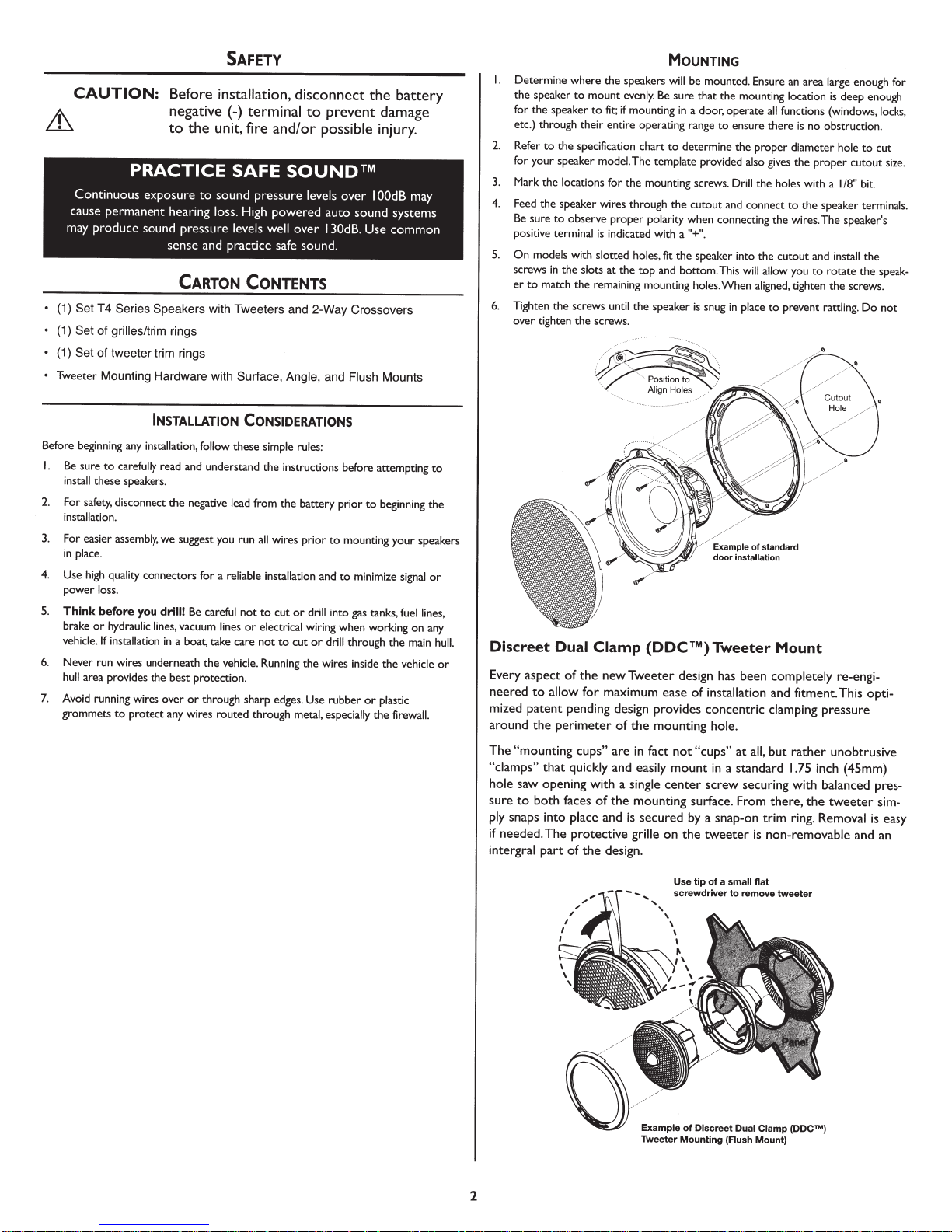
5.
On models
screws
er
to
6. Tighten the screws
over tighten the screws.
Discreet
Every
aspect
neered
mized
patent
around
The
"mounting
"clamps
hole
saw
sure
to
ply
snaps
if
needed.
intergral
to
mount
evenly.
to
fit;
if
mounting
to
the specification chart
model.
The
the
locations
for the mounting screws.
the
speaker wires through
sure
to
observe proper
terminal
is
with
slotted holes,
in
the slots
match the remaining mounting
Dual
Clamp
of
the
to
allow
for
pending
the
perimeter
cups"
"
th
at
quickly
opening
both
part
into
The
with
faces
of
place
protective
of
the
polarity
indicated with a
at
the top and bottom. This
until
the
speaker
(DOC™)
new
Tweeter
maximum
design
of
the
are
in
fact
and
easily
a
single
the
mounting
and
is
secured
grille
design.
MouNTING
will
be mounted. Ensure
Be
sure that the mounting
in
a door, operate
to
ensure there
to
determine the proper diameter
template
provided
Drill
the
cutout and connect
when connecting the wires. The speaker's
an
location
all
functions (windows,
is
also
gives
the proper cutout size.
the holes
to
area
no obstruction.
with a
the
"+".
fit
the speaker into the cutout and
holes.
is
design
ease
of
provides
mounting
not
"cups"
mount
center
surface.
by
on
the
will
When
snug
in
place
Tweeter
has
been
installation
concentric
hole
.
at
all,
in
a
standard
screw
securing
From
a
snap-on
tweeter
allow
you
aligned,
tighten the screws.
to
prevent
Mount
completely
and
fitment.This
clamping
but
rather
1.75
with
there,
the
trim
ring.
is
non-removable
large
enough for
is
deep enough
locks,
hole
to
cut
1/8"
bit.
speaker terminals.
install
rotate
the
rattling.
re-engi-
pressure
unobtrusive
(45mm)
balanced
tweeter
Removal
and
the
speak-
Do not
opti-
pres-
sim-
is
an
to
inch
easy
Use
tip
of
a
small
flat
to
remove
tweeter
Dual
Clamp
(Flush Mount}
(DDCTM)
Example
Tweeter
screwdriver
of
Discreet
Mounting
2
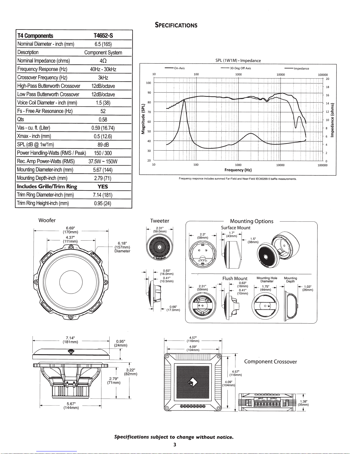
SPECIFICATIONS
T 4
Components
Nominal
DiameterDescription
Nominal
Impedance
Frequency
Crossover
High
Low
Voice
Fs
-
Pass
Pass
-
Free
Coil
Response
Frequency
Butterworth
Butterworth
Diameter-
Nr
Qts
Vas
-
cu.
ft.
(Liter)
Xmax-
inch
SPL
(dB@
Power
Handling-Watts
Rec.
Amp
Power-Watts
Mounting
Mounting
Includes
Trim
Trim
Diameter-inch
Depth-inch
Grille/Trim
Ring
Diameter-inch
Ring
Height-inch
inch
(ohms)
(Hz)
(Hz)
Crossover
Crossover
inch
Resonance
(mm)
1w/1m)
(RMS
(mm)
(mm)
(mm)
(mm)
(Hz)
I
(RMS)
(mm)
Ring
(mm)
Component
Peak)
37.5W-150W
T4652-S
6.5
(165)
System
40
40Hz-
30kHz
3kHz
12dB/octave
12dB/octave
1.5
(38)
52
0.58
0.59
(16.74)
0.5
(12.6)
89dB
150/300
5.
67
(144)
2.79
(71)
YES
7.14
(181)
0.95
(24)
SPL
(1
W1
M)
• Impedance
-on-
Ax
is
10
10
100
100
Frequency responce
includes
-
Frequency (Hz)
summed
Far
30-D
eg
Off
Axis
1000
1000
-F
ield
and
Near-Field IEC60268-5 baffle
- Impedance
10000
10000
measurements.
100000
Woofer
6.69"
(170mm)
0
6.18"
(157mm)
Diam
eter
(82
3.22"
mm)
Tweeter Mounting Options
Surface
Mount
--
4.57"
(116mm) _ _
4.09"
(104mm)
--
......._,
.j
1--
--
f--
Component Crossover
5.67"
(144mm)
Specifications
subject
to
change
3
without
notice.
 Loading...