

Rockford Fosgate T252-S - 5.25'', T2652~S - 6.5'', T252-S, T2652-S, T2T-S Installation & Operation Manual

I
J
w
E
Component
Systems
T252-S
T2652~S
T2T-S
Serial
Number:
------
-
T\Neeter
-
5.25''
6.5''
-
System
Installation
Installation
lnstalaci6n
Einbau
lnstallazione
Date
und
Purchase:
of
Operation
&
fonctionnement
et
funcionamiento
y
Betrieb
funzionamento
e
------
.&.
CAUTION:
Continuous
cause
may
PRACTICE
permanent
produce
SAFETY
Before installation, disconnect
(-)
unit, fire
SAFE
sound
levels well
and
practice
terminal
and/or
SOUND™
pressure
powered
safe
over
sound.
negative
to
the
exposure
sound
to
hearing loss. High
pressure
sense
the
to
prevent damage
possible injury.
levels
over I OOdB
auto
sound
130dB. Use
battery
may
systems
common
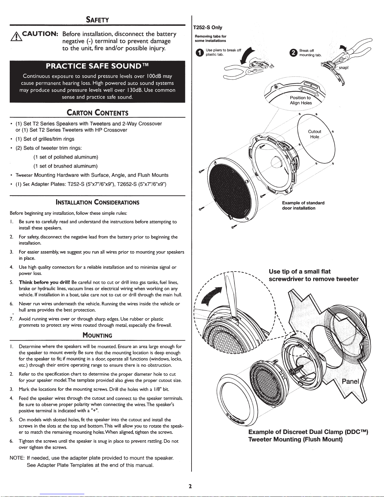
T252-S Only
Removing
tabs
some
installations
Use pliers
plastic tab.
0
for
to
break
o~
~··<
~~
A
Breakoff
V mounting tab.
Align
Holes
CARTON
• (1)
Set
T2
Series
Speakers
or
(1)
Set
T2
Series
Tweeters
• (1)
Set
of
grilles/trim rings
Sets
of
tweeter
• (2)
(1
set
(1
set
• Tweeter
•
Before beginning
I.
2.
3.
4.
5.
6.
7.
Mounting
(I)
Set
Adapter
Be
sure
to
install these
For
safety,
installation.
For easier
in
Use
power
Think
brake
vehicle.
Never run wires underneath the vehicle. Running the wires inside the vehicle
hull
Avoid running wires over
grommets
disconnect the negative
assembly,
place.
high
quality connectors
loss.
before you
or
hydraulic
If
installation
area
provides the best protection.
to
trim rings:
of
polished
of
brushed
Plates:
aluminum)
aluminum)
Hardware
T252-S
INSTALLATION
any
installation, follow these simple rules:
carefully read
speakers.
protect
and
we
suggest
for
drill!
Be
lines,
vacuum
in
a boat, take care
or
any
wires routed through metal, especially the firewall.
CONTENTS
with
Tweeters
with
with
Surface,
(5"x7"/6"x9"),
understand the instructions before attempting
lead
you run
a reliable installation
careful
not
lines
through sharp
and
2-Way
Crossover
HP
Crossover
Angle,
and
Flush
T2652-S
(5"x7"/6"x9")
CONSIDERATIONS
from the battery
all
wires
to
cut
or
or
electrical wiring when working on
not
to
cut
edges.
prior
prior
to
mounting your
and
to
drill into
or
drill through the
Use
rubber
to
beginning the
minimize
gas
tanks,
or
plastic
Mounts
signal
fuel
main
to
speakers
or
lines,
any
hull.
or
Example
door
installation
Use
tip
of
a small
screwdriver
of
standard
to
flat
remove
tweeter
MOUNTING
I. Determine where the
the speaker
for
etc.) through their entire operating
2.
Refer
for
3.
Mark the locations
4.
Feed
Be
positive terminal
5.
On
screws
er
to
6.
Tighten the screws until the speaker
over tighten the screws.
NOTE:
to
the speaker
to
the specification chart
your speaker model. The template provided
the speaker wires through the cutout
sure
to
observe proper polarity when connecting the wires. The speaker's
models with slotted holes, fit the speaker into the cutout
in
the slots at the
match the remaining mounting holes.
If
needed,
See
Adapter
speakers
will
be
mount
evenly.
to
fit;
for
is
indicated with a
use
Plate
Be
if
mounting
the mounting screws. Drill the holes with a
top
the
adapter
Templates
mounted.
sure that the mounting location
in
a door, operate
range
to
determine the proper diameter hole
"+".
and
bottom. This will allow you
is
snug
plate
at
to
ensure there
also
and
connect
When
in
place
provided
the
end
Ensure
all
gives
aligned,
to
to
of
this
an
area
large enough
is
functions (windows, locks,
the proper cutout
to
tighten the screws.
prevent rattling.
mount
manual.
deep
is
no obstruction.
1/8"
the speaker terminals.
and
install the
to
rotate the
the
speaker.
enough
to
cut
bit.
speak-
Do
for
size.
not
Example
Tweeter
of
Discreet Dual Clamp (DOC™)
Mounting
(Flush Mount)
2
fEATURES
Discreet Dual
Tweeter
Every aspect
completely
installation
of
ease
patent pending design provides concentric
clamping pressure around
mounting
The
but
and
hole
securing with
of
simply
snap-on trim ring.
The
non-removable
hole.
"mounting cups"
rather
easily
saw opening with a
the mounting surface. From
snaps into
protective
Clamp
Mount
the
of
re-engineered
and fitment. This
unobtrusive
in
mount
balanced
place
Removal
grille
and an
(DOC™)
new Tweeter design has been
for maximum
allow
to
imized
opt
perimeter
the
"cups"
not
fact
in
are
quickly
single
is
is
tweeter
that
1.75
center
both faces
to
there
secured
if
easy
part
inch (45mm)
screw
the
,
by
needed.
is
the
of
"clamps"
a standard
pressure
and
the
on
intergral
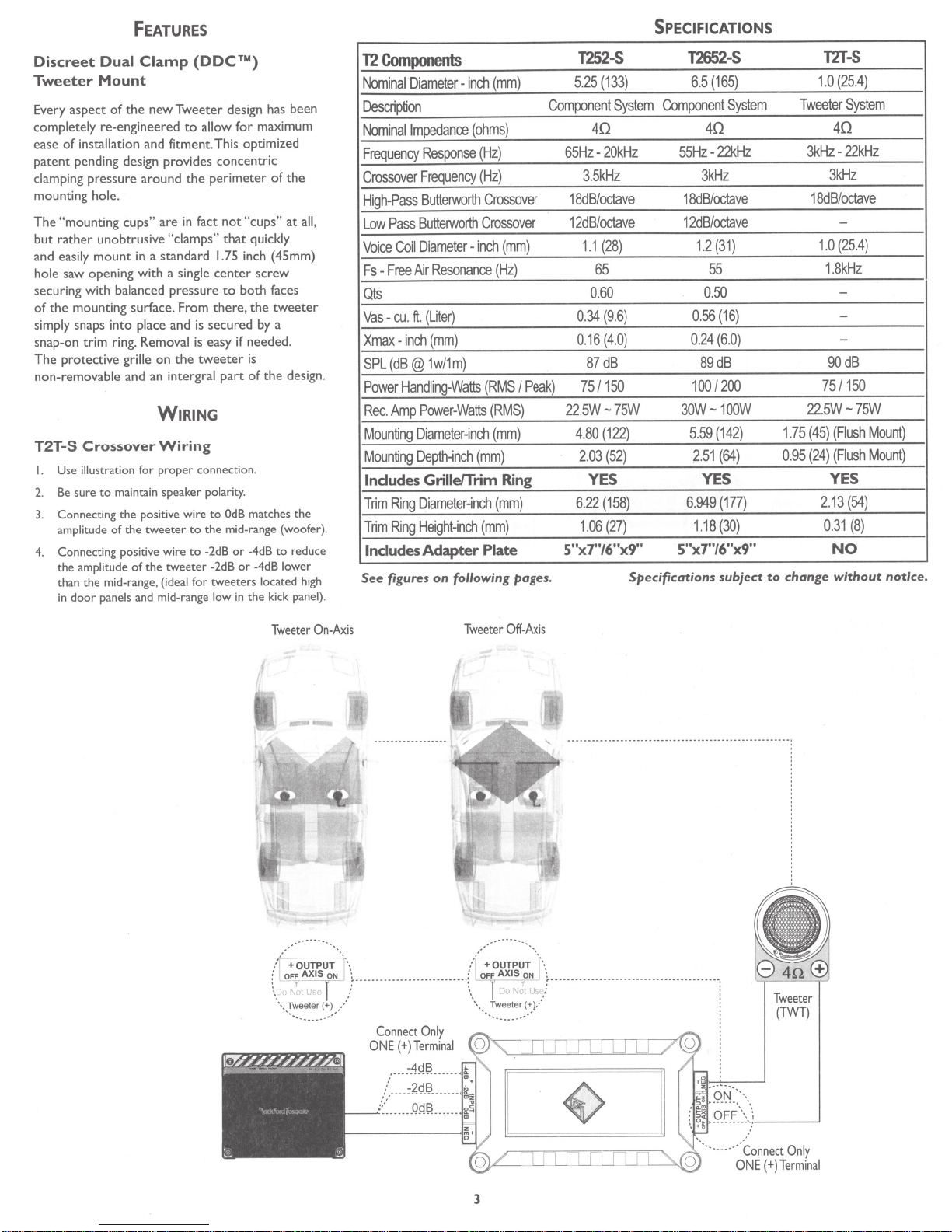
WIRING
Wiring
connection.
proper
for
maintain speaker polarity.
OdB
positive wire
the
tweeter
the
the
of
(ideal
and mid-range
to
to
tweeter
for tweeters
to
mid-range (woofer).
the
or
-2dB
-2dB
low
matches the
-4dB
-4dB
or
located
the kick
in
Use
I.
Be
amplitude
the
than
in
Crossover
illustration
to
sure
of
amplitude
mid-range,
the
panels
door
T2T-S
2.
3. Connecting
4. Connecting positive wire
the
of
all,
at
tweeter
a
design.
reduce
to
lower
high
panel).
Components
T2
Nominal
DiameterDescription
Nominal
Frequency
Crossover
High-Pass
Low
Voice
Fs
Impedance
Pass
Coil
Free
-
Response
Frequency
Butterworth
Butterworth
Diameter-
Air
Qts
(Liter)
.
ft
.
cu
-
Vas
inch
Xmax-
1w/1m)
(dB@
SPL
Handling-Watts
Power
Power-Watts
Amp
Rec.
Mounting
Mounting
Includes
Trim
Trim
Includes
See
Diameter~nch
Depth-inch
Grille/Trim
Diameter~nch
Ring
Height-inch
Ring
Adapter Plate
figures
(mm)
inch
(ohms)
(Hz)
(Hz)
Crossover
Crossover
inch
Resonance
(Hz)
(mm)
(RMS
(RMS)
(mm)
(mm)
(mm)
(mm)
following pages.
on
(mm)
Peak)
I
Ring
1252-S
(133)
25
5.
Component
40
20kHz
65Hz-
3.5kHz
18dB/octave
12dB/octave
(28)
1.1
65
0.60
(9.6)
0.34
(4.0)
16
0.
87dB
75/150
.5W-75W
22
(122)
80
4.
(52)
03
2.
YES
(158)
6.22
(27)
06
1.
5"x7"/6"x9"
SPECIFICATIONS
12652-S
(165)
6.5
System
Component
40 40
55Hz-22kHz
3kHz 3kHz
18dB/octave
12dB/octave
(31)
1.2
55
0.50
(16)
0.56
(6.0)
0.24
89dB
100/200
30W- 1
(142)
59
5.
(64)
51
2.
YES YES
(177)
6.949
(30)
1.18
5"x7"/6"x9"
Specifications subject
System
00W
1.75
0.
change
to
T2T-S
1.0
Tweeter
3kHz-
18dB
1.0
1.8kHz
75
.5W-75W
22
(45)
(24)
95
2.13
0.
(25.4)
System
22kHz
octave
/
-
25.4
(
-
-
-
90dB
150
/
(Flush
(Flush
(54)
(8)
31
NO
without
)
Mount)
Mount)
notice.
Tweeter
On-Axis
Connect
ONE(+)
.....
....
/
·
..
,:
.
........
Only
Terminal
...
4Q~
-.
...... .
~
-
9
~~
.... -
OR~
-
Tweeter
Off-Axis
.
··
ot-t
0i='f=\\
-''i------'
Tweeter
(TWT)
·-(+)Termi
~--'"'o,I:·-'J
3
ONE
al
n
Only
Connect
---··
..
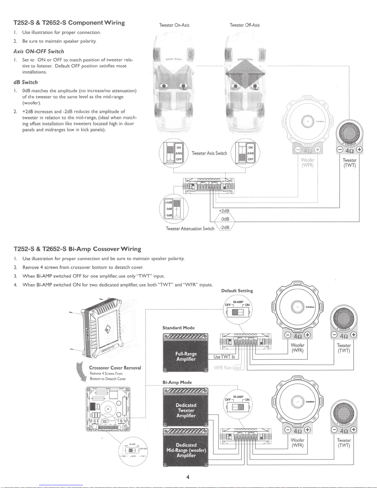
T252-S & T2652-S
I.
Use
illustration for
sure
to
2. Be
maintain
Component
proper
connection.
speaker
polarity.
Axis ON-OFF Switch
I.
Set
to
ON
or
OFF
to
amplitude
to
the
to
match position
position
(no
same
level as
the
mid-range, (ideal
tweeters
in kick
tive
to
listener. Default OFF
installations.
dB
Switch
I.
OdB
matches
tweeter
in
relation
the
of
the
(woofer).
2. +2dB increases and -2dB reduces
tweeter
ing offset installation like
panels and midranges low
of
satisfies
increase/
the
the
amplitude
located high
panels).
Wiring
tweeter rela-
most
no
attenuation)
mid-range
of
when
in
match-
door
Tweeter On-Ax
Tweeter Attenuati
is
Tweeter
Axis Swi
··-·· ---
. .
·----
----------------------------··:-··-----
+2dB
.....
--
on
Switch
\.:?~
Tweeter Off-Axis
tch
Woofe
r
.-
--
(WFR)
-----·
u
~~~
....
-:
~----------------------------------------~
-
~-
·/
Tweete
(
TWT
r
)
T252-S & T2652-S
I.
Use
illustration
2. Remove 4 screws from
When
3.
When
4.
BI-AMP
BI-AMP
for
proper
switched OFF
switched
Bi-Amp
connection
crossover
for
ON
for
\
Cossover
and be
bottom
one
amplifie
two
dedicated amplifier, use
Crossover
Remove
4 Sc
Bottom
to
sure
to
detatch
r,
use only "
Cover
rews From
Detatch Cov
Wiring
to
maintain speaker polarity.
cover.
TWT
" input.
both "TWT
--------------------
Removal
er
_____
___
___
" and "
WFR
--
---- ----
':'_i_~~':!!P
..
~~~':'
" inputs.
------
--
-------------
__________________ _____
Default
/
OFF-, rON
~-
.. ~ IIIB
...
. _
_____
/
OFF-, rON
\.
.
~
..
_
__
Setting
·-
81-AMP
___
_
--
~ - -
B~AMP
Elllll
..
.
-._
\
~
)
...
-._
·.
~
)
..
··
Tweet
(TWT)
er
T
wee
ter
(TWT)
4
 Loading...