


 Loading...
Robustel GoRugged M1000 Pro V2
Dual SIM Industrial Serial to Cellular Gateway
For GSM/GPRS/EDGE/UMTS Networks
User Guide
Document Name: |
User Guide |
Firmware: |
2.5.0 |
M1000 Pro V2 Configurator: |
2.5.0 |
Date: |
2013-11-19 |
Status: |
Confidential |
Doc ID: |
RT_UG_M1000 Pro V2_v.2.0.0 |
www.robustel.com

Robustel GoRugged M1000 Pro V2 User Guide
About This Document
This document describes the hardware and software of the Robustel M1000 Pro V2 Dual SIM Industrial Serial to Cellular Gateway.
Copyright© Guangzhou Robustel Technologies Co., Limited
All Rights Reserved.
Trademarks and Permissions
Robustel are trademark of Guangzhou Robustel Technologies Co. Limited.
All other trademarks and trade names mentioned in this document are the property of their respective holders.
Disclaimer
No part of this document may be reproduced in any form without the written permission of the copyright owner. The contents of this document are subject to revision without notice due to continued progress in methodology, design and manufacturing. Robustel shall have no liability for any error or damage of any kind resulting from the use of this document.
Technical Support Contact Information
Tel: +86-18924045664
Fax: +86-20-82321505
E-mail: support@robustel.com
Web: www.robustel.com
RT_UG_M1000 Pro V2_v.2.0.0 |
19.11.2013 |
1 / 69 |
Confidential |
|
|

Robustel GoRugged M1000 Pro V2 User Guide
Important Notice
Due to the nature of wireless communications, transmission and reception of data can never be guaranteed. Data may be delayed, corrupted (i.e., have errors) or be totally lost. Although significant delays or losses of data are rare when wireless devices such as the gateway are used in a normal manner with a well-constructed network, the gateway should not be used in situations where failure to transmit or receive data could result in damage of any kind to the user or any other party, including but not limited to personal injury, death, or loss of property. Robustel accepts no responsibility for damages of any kind resulting from delays or errors in data transmitted or received using the gateway, or for failure of the gateway to transmit or receive such data.
Safety Precautions
General
The gateway generates radio frequency (RF) power. When using the gateway care must be taken on safety issues related to RF interference as well as regulations of RF equipment.
Do not use your gateway in aircraft, hospitals, petrol stations or in places where using cellular products is prohibited.
Be sure that the gateway will not be interfering with nearby equipment. For example: pacemakers or medical equipment. The antenna of the gateway should be away from computers, office equipment, home appliance, etc.
An external antenna must be connected to the gateway for proper operation. Only uses approved antenna with the gateway. Please contact authorized distributor on finding an approved antenna.
Always keep the antenna with minimum safety distance of 26.6 cm or more from human body. Do not put the antenna inside metallic box, containers, etc.
Note: Some airlines may permit the use of cellular phones while the aircraft is on the ground and the door is open. Gateway may be used at this time.
Using the gateway in vehicle
Check for any regulation or law authorizing the use of GSM in vehicle in your country before installing the gateway.
The driver or operator of any vehicle should not operate the gateway while cellular in control of a vehicle.
Install the gateway by qualified personnel. Consult your vehicle distributor for any possible interference of electronic parts by the gateway.
The gateway should be connected to the vehicle’s supply system by using a fuse-protected terminal in the vehicle’s fuse box.
Be careful when the gateway is powered by the vehicle’s main battery. The battery may be drained after extended period.
Protecting your gateway
To ensure error-free usage, please install and operate your gateway with care. Do remember the follow:
Do not expose the gateway to extreme conditions such as high humidity / rain, high temperatures, direct sunlight, caustic / harsh chemicals, dust, or water.
Do not try to disassemble or modify the gateway. There is no user serviceable part inside and the warranty would be void.
RT_UG_M1000 Pro V2_v.2.0.0 |
19.11.2013 |
2 / 69 |
Confidential |
|
|

Robustel GoRugged M1000 Pro V2 User Guide
Do not drop, hit or shake the gateway. Do not use the gateway under extreme vibrating conditions.
Do not pull the antenna or power supply cable. Attach/detach by holding the connector.
Connect the gateway only according to the instruction manual. Failure to do it will void the warranty.
In case of problem, please contact authorized distributor.
RT_UG_M1000 Pro V2_v.2.0.0 |
19.11.2013 |
3 / 69 |
Confidential |
|
|
Robustel GoRugged M1000 Pro V2 User Guide
Regulatory and Type Approval Information
Table 1: Directives
Directive of the European Parliament and of the Council of 27 January 2003
2002/95/EC on the restriction of the use of certain hazardous substances in electrical and electronic equipment (RoHS)
2002/96/EC
Directive of the European Parliament and of the Council on waste electrical and electronic equipment (WEEE)
Directive of the European Parliament and of the Council of 8 December
2003/108/EC 2003 amending directive 2002/96/ec on waste electrical and electronic equipment (WEEE)
Table 2: Standards of the Ministry of Information Industry of the People’s Republic of China
SJ/T “Requirements for Concentration Limits for Certain Hazardous Substances in Electronic Information
11363-2006 Products” (2006-06).
“Marking for Control of Pollution Caused by Electronic Information Products”
(2006-06).
According to the “Chinese Administration on the Control of Pollution caused
SJ/T
by Electronic Information Products” (ACPEIP) the EPUP, i.e., Environmental
11364-2006
Protection Use Period, of this product is 20 years as per the symbol shown here, unless otherwise marked. The EPUP is valid only as long as the product is operated within the operating limits described in the Hardware Interface Description.
Please see Table 3 for an overview of toxic or hazardous substances or elements that might be contained in product parts in concentrations above the limits defined by SJ/T 11363-2006.
Table 3: Toxic or hazardous substances or elements with defined concentration limits
Name of the part |
Hazardous substances |
|
|
|
|
||
|
|
|
|
|
|
||
(Pb) |
(Hg) |
(Cd) |
(Cr(VI)) |
(PBB) |
(PBDE) |
||
|
|||||||
Metal Parts |
o |
o |
o |
o |
o |
o |
|
|
|
|
|
|
|
|
|
Circuit Modules |
x |
o |
o |
o |
o |
o |
|
|
|
|
|
|
|
|
|
Cables and Cable Assemblies |
o |
o |
o |
o |
o |
o |
|
|
|
|
|
|
|
|
|
Plastic and Polymeric parts |
o |
o |
o |
o |
o |
o |
|
|
|
|
|
|
|
|
|
|
|
|
|
|
|
|
|
RT_UG_M1000 Pro V2_v.2.0.0 |
19.11.2013 |
4 / 69 |
Confidential |
|
|

Robustel GoRugged M1000 Pro V2 User Guide
Revision History
Updates between document versions are cumulative. Therefore, the latest document version contains all updates made to previous versions.
Release Date |
Firmware Version |
Doc Version |
Details |
2013-11-19 |
2.5.0 |
v.2.0.0 |
Update User Guide to firmware version 2.5.0 |
|
|
|
|
RT_UG_M1000 Pro V2_v.2.0.0 |
19.11.2013 |
5 / 69 |
Confidential |
|
|

Robustel GoRugged M1000 Pro V2 User Guide
|
|
Contents |
|
Chapter 1. |
Product Concept......................................................................................................................................... |
8 |
|
1.1 |
Overview .................................................................................................................................................... |
8 |
|
1.2 |
Packing List ................................................................................................................................................. |
9 |
|
1.3 |
Specifications ........................................................................................................................................... |
10 |
|
1.4 |
Dimensions............................................................................................................................................... |
12 |
|
1.5 |
Selection and Ordering Data .................................................................................................................... |
12 |
|
Chapter 2. |
Installation................................................................................................................................................ |
13 |
|
2.1 |
Overview .................................................................................................................................................. |
13 |
|
2.2 |
LED Indicators........................................................................................................................................... |
13 |
|
2.3 |
PIN assignment......................................................................................................................................... |
14 |
|
2.4 |
Install SIM Card......................................................................................................................................... |
14 |
|
2.5 |
Connect the External Antenna (SMA Type).............................................................................................. |
15 |
|
2.6 |
Connect the Gateway to External Device................................................................................................. |
16 |
|
2.7 |
Mount the Gateway ................................................................................................................................. |
16 |
|
2.8 |
Ground the Gateway ................................................................................................................................ |
17 |
|
2.9 |
Power Supply............................................................................................................................................ |
17 |
|
Chapter 3. Operate the Gateway ............................................................................................................................... |
18 |
||
3.1 |
Working Mode Overview ......................................................................................................................... |
18 |
|
3.2 |
M1000 Pro V2 Configurator Overview ..................................................................................................... |
18 |
|
3.2.1 |
Management via RS-232 port........................................................................................................... |
19 |
|
3.2.2 |
Management via TCP connection..................................................................................................... |
20 |
|
3.2.3 |
Operation Area Introduction ............................................................................................................ |
21 |
|
3.2.4 |
Export and Import Profiles ............................................................................................................... |
23 |
|
3.2.5 |
COM.................................................................................................................................................. |
25 |
|
3.2.6 |
Basic.................................................................................................................................................. |
26 |
|
3.2.7 |
GPRS.................................................................................................................................................. |
27 |
|
3.2.8 |
Connection........................................................................................................................................ |
29 |
|
3.2.9 |
Dual SIM............................................................................................................................................ |
32 |
|
3.2.10 |
DDNS................................................................................................................................................. |
34 |
|
3.2.11 |
Phone Book....................................................................................................................................... |
35 |
|
3.2.12 |
Wakeup............................................................................................................................................. |
36 |
|
3.2.13 |
Reboot .............................................................................................................................................. |
38 |
|
3.2.14 |
Modbus............................................................................................................................................. |
39 |
|
3.2.15 |
Advanced .......................................................................................................................................... |
41 |
|
3.2.16 |
NMS .................................................................................................................................................. |
43 |
|
3.2.17 |
Status ................................................................................................................................................ |
45 |
|
3.2.18 |
Management .................................................................................................................................... |
47 |
|
Chapter 4. |
Typical Applications.................................................................................................................................. |
50 |
|
4.1 |
Overview .................................................................................................................................................. |
50 |
|
4.2 |
Typical Applications.................................................................................................................................. |
51 |
|
4.2.1 |
TCP Client Mode ............................................................................................................................... |
51 |
|
4.2.2 |
TCP Server Mode .............................................................................................................................. |
53 |
|
RT_UG_M1000 Pro V2_v.2.0.0 |
19.11.2013 |
6 / 69 |
Confidential |
|
|

Robustel GoRugged M1000 Pro V2 User Guide
4.2.3 |
UDP Mode ........................................................................................................................................ |
56 |
|
4.2.4 |
Virtual COM Mode............................................................................................................................ |
57 |
|
Chapter 5. |
Appendix .................................................................................................................................................. |
58 |
|
5.1 |
Factory Settings........................................................................................................................................ |
58 |
|
5.2 |
SMS Command for Remote Control ......................................................................................................... |
58 |
|
5.2.1 |
SMS Commands Structure................................................................................................................ |
58 |
|
5.2.2 |
SMS Control Steps ............................................................................................................................ |
58 |
|
5.2.3 |
SMS Commands List ......................................................................................................................... |
59 |
|
5.2.4 |
SMS Control examples...................................................................................................................... |
65 |
|
5.3 |
Troubleshooting ....................................................................................................................................... |
67 |
|
5.3.1 The gateway’s LED does not light: .................................................................................................... |
67 |
||
5.3.2 No connection with gateway through serial link .............................................................................. |
67 |
||
5.3.3 GPRS/UMTS connection cannot be established ............................................................................... |
67 |
||
5.4 |
Terms and Abbreviations.......................................................................................................................... |
67 |
|
RT_UG_M1000 Pro V2_v.2.0.0 |
19.11.2013 |
7 / 69 |
Confidential |
|
|

Robustel GoRugged M1000 Pro V2 User Guide
Chapter 1. Product Concept
1.1Overview
Robustel GoRugged M1000 Pro V2 is a rugged serial to cellular gateway with dual SIM offering state-of-the-art 2G/3G connectivity for machine to machine (M2M) applications.
Dual SIM redundancy for continuous cellular connection.
Various SIM backup polices: PING/Monthly data traffic/Roaming.
Auto GPRS/UMTS connection (no AT commands required).
Support CSD communication (only receive CSD call).
Transparent TCP and UDP socket connections.
Supports Virtual COM (COM port redirector).
Supports ICMP, DDNS, Telnet.
Supports RobustLink (Centralized M2M management platform).
Supports Modbus gateway (Modbus RTU to Modbus TCP).
Supports Modbus master polling, collects data at preset interval and sends to RobustLink.
Various reboot policies: SMS/Caller ID/Timing.
Various dial-up policies: Always Online/Connect On Demand.
Remote configuration via RobustLink/TCP/SMS.
Remote firmware upgrade via RobustLink/TCP.
RS232/RS485 selectable by software.
Six LED indicators provide signal strength and running status.
Watchdog for reliable communications.
Wide range input voltages from 9 to 36 VDC and extreme operating temperature.
The metal enclosure can be mounted on a DIN-rail or on the wall, also with extra ground screw.
RT_UG_M1000 Pro V2_v.2.0.0 |
19.11.2013 |
8 / 69 |
Confidential |
|
|

Robustel GoRugged M1000 Pro V2 User Guide
1.2Packing List
Check your package to make certain it contains the following items:
Robustel GoRugged M1000 Pro V2 gatewayx1
2-pin pluggable terminal block for power connector x1
CD with user guide and configuration utility x1
Note: Please notify your sales representative if any of the above items are missing or damaged.
Optional accessories (can be purchased separately):
SMA antenna (Stubby antenna or Magnet antenna optional) x1
Stubby antenna |
Magnet antenna |
Serial cable for RS232 (DB9 Female to DB9 Male, 1 meter) x1
Wall Mounting Kit
RT_UG_M1000 Pro V2_v.2.0.0 |
19.11.2013 |
9 / 69 |
Confidential |
|
|
Robustel GoRugged M1000 Pro V2 User Guide
35mm Din-Rail mounting kit
AC/DC Power Supply Adapter (12VDC, 1A) x1
DB9 Male to terminal block for serial port
1.3Specifications
Cellular Interface
Standards: GSM/GPRS/EDGE/UMTS
GPRS: max. 86 kbps (DL & UL), class 10
EDGE: max. 236.8 kbps (DL & UL), class 12
UMTS: max. 384 kbps (DL & UL)
Frequency: 850/900/1800/1900 MHz for GPRS/EDGE, 850/900/1800/1900/2100 MHz for UMTS/HSPA+
CSD: Up to 14.4 kbps
SIM: 2 x (3V & 1.8V)
RT_UG_M1000 Pro V2_v.2.0.0 |
19.11.2013 |
10 / 69 |
Confidential |
|
|

Robustel GoRugged M1000 Pro V2 User Guide
Antenna Interface: SMA Female
Serial Interface
Number of Ports: 1 x DB9 Female
Serial Standards: RS232 and RS485
ESD Protection: ±15KV
Baudrate: 1200bps to 115200bps
RS-232: TxD, RxD, RTS, CTS, GND
RS-485: Data+ (A), Data- (B), GND
System
LED Indicators: PWR, RUN, NET and 3 level RSSI
Real Time Clock: Built-in RTC with button battery
Watchdog and Timer: Built-in watchdog and timer
Software
IP protocols: PPP, TCP, UDP, ICMP, DDNS, Telnet
Serial Port: TCP client/server, UDP, Modbus RTU to Modbus TCP, Virtual COM (COM port redirector)
RobustLink: Centralized M2M management platform
Power Supply and Consumption
Power Supply Interface: 2-pin 5mm pluggable terminal block
Input Voltage: 9 to 36 VDC
Power Consumption: Idle: 50-60 mA@12 V
Data Link: 100 to 200 mA (peak)@12 V
Physical Characteristics
Housing & Weight: Metal, 300g
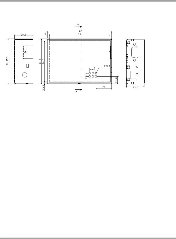
Dimension(L x W x H): 102 x 71 x 29 mm
Installation: 35mm Din-Rail or wall mounting or desktop
RT_UG_M1000 Pro V2_v.2.0.0 |
19.11.2013 |
11 / 69 |
Confidential |
|
|
Robustel GoRugged M1000 Pro V2 User Guide
1.4Dimensions
1.5Selection and Ordering Data
Please refer to corresponding M1000 Pro V2 datasheet.
RT_UG_M1000 Pro V2_v.2.0.0 |
19.11.2013 |
12 / 69 |
Confidential |
|
|
Robustel GoRugged M1000 Pro V2 User Guide
Chapter 2. Installation
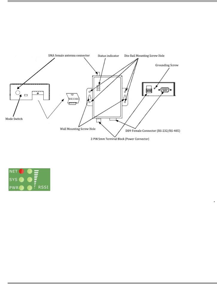
2.1Overview
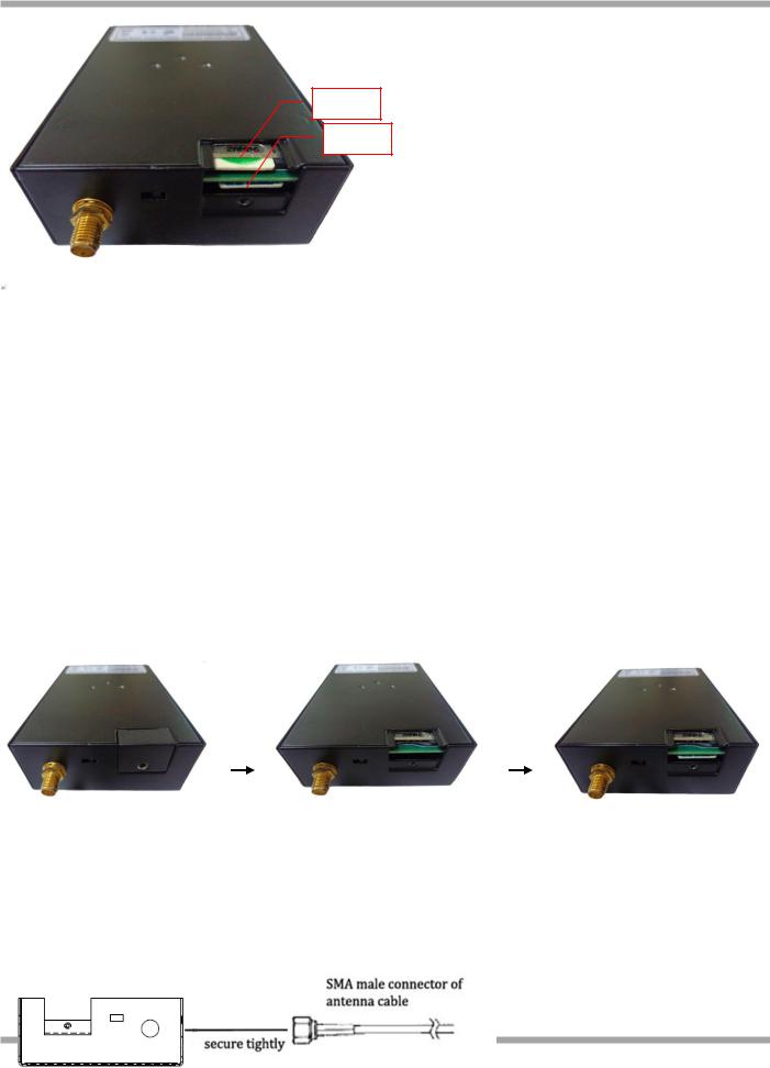
SIM Cover
2.2LED Indicators
|
Name |
|
|
Color |
|
|
Function |
|
|
|
|
|
|
|
|||
|
|
|
|
|
|
|
|
|
|
|
|
|
|
|
|
|
|
|
RSSI (3 LEDs) |
Green |
|
Cellular signal strength level |
||||
|
|
|
|
|
|
|
|
|
|
|
|
|
|
|
|
Indicating the GPRS/UMTS connection status. |
|
|
|
|
|
|
|
|
Register to network: blinking every 3s |
|
|
NET |
Red |
|
Device running error alarm: always on |
||||
|
|
|
|
|
|
|
Wireless module rebooting and searching GPRS/UMTS network: blinking every 1s |
|
|
|
|
|
|
|
|
Note: RSSI LEDs which will be explained later show the specific error info. |
|
|
|
|
|
|
|
|
Indicating the system status. |
|
|
|
|
|
|
|
|
System is booting: blinking every 0.5s |
|
|
SYS |
Green |
|
System is running normally but without any GPRS/UMTS connection: blinking every 1s |
||||
|
|
|
|
|
|
|
System is running normally and GPRS/UMTS connection established: blinking every 3s |
|
|
|
|
|
|
|
|
System is running abnormally: 2.5s on and 0.5s out during every 3s |
|
|
|
|
|
|
||||
|
PWR |
Green |
|
On when DC power connected |
||||
|
|
|
|
|
|
|
|
|
RT_UG_M1000 Pro V2_v.2.0.0 |
19.11.2013 |
13 / 69 |
Confidential |
|
|
Robustel GoRugged M1000 Pro V2 User Guide
|
RSSI LEDs |
|
|
Function |
|
|
None |
|
|
No signal or SIM card not installed properly |
|
|
|
|
|
|
|
|
1 bar (Only the first LED is on) |
|
|
Weak or insufficient signal (SMS only) |
|
|
|
|
|
|
|
|
2 bars (The first and the second LED are on) |
|
|
Average signal (GSM/GPRS/UMTS connections) |
|
|
|
|
|
|
|
|
3 bars (All the RSSI LEDs are on) |
|
|
Exceptional signal (GSM/GPRS/UMTS connections) |
|
|
|
|
|
|
|
|
The first and the second LED are blinking every 1 second |
|
|
PIN code error |
|
|
|
|
|
|
|
|
The third LED is blinking every 1 second |
|
|
PIN code error and need to use PUK code to unlock it |
|
|
The second LED is blinking every 1 second |
|
|
No SIM card or SIM card not installed properly |
|
|
|
|
|
|
|
|
The third LED is blinking every 1 seconds |
|
|
Wireless module communication error, no AT |
|
|
|
|
command response. |
|
|
|
|
|
|
|
|
|
|
|
|
|
|
|
The first and the third LED are blinking every 1 second |
|
|
Cannot register to network or SIM card is unavailable |
|
|
|
|
|
|
|
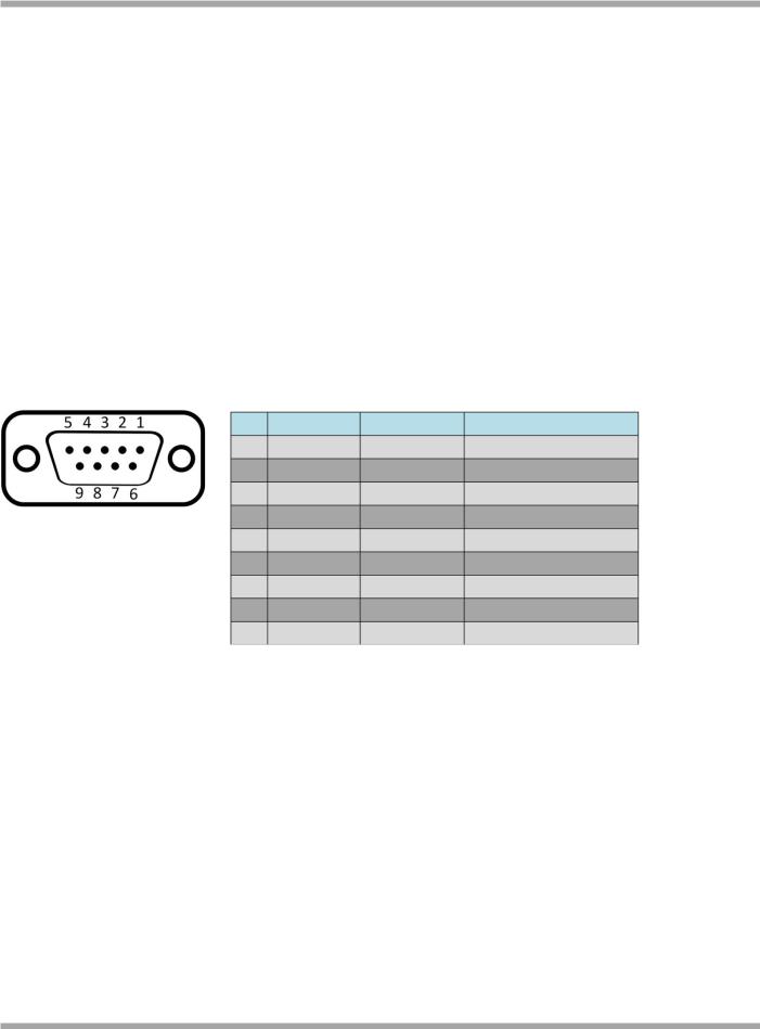
2.3PIN assignment
DB9 Female Connector
PIN |
RS232 |
RS485 (2-wire) |
Direction |
1 |
|
Data+ (A) |
- |
2 |
RXD |
|
M1000 Pro V2 Device |
3 |
TXD |
|
Device M1000 Pro V2 |
4 |
|
|
- |
5 |
GND |
|
- |
6 |
|
Data- (B) |
- |
7 |
RTS |
|
Device M1000 Pro V2 |
8 |
CTS |
|
M1000 Pro V2 Device |
9 |
|
|
- |
2.4Install SIM Card
Be sure to insert a SIM card before you use the gateway.
Note: A SIM card set with PIN code cannot be used normally in the gateway without the correct PIN code.
Make sure to disconnect the adapter and switch off your gateway before inserting or removing your SIM/USIM card.
RT_UG_M1000 Pro V2_v.2.0.0 |
19.11.2013 |
14 / 69 |
Confidential |
|
|
Robustel GoRugged M1000 Pro V2 User Guide
SIM 2
SIM 1
Inserting SIM Card
1.Make sure your adapter is disconnected.
2.Use a screwdriver to unscrew the screw on the cover, and then remove the cover, you could find the SIM Card slot.
3.Insert the SIM card, and you need press the SIM card with your fingers until you hear “a cracking sound”. Then use a screwdriver to screw the cover.
Removing SIM card
1.Make sure your adapter is disconnected.
2.Press the SIM card until you hear “a cracking sound”, then the SIM card will pop up to be pulled out.
Note:
1.Don’t forget screw the cover for again-theft.
2.Don’t touch the metal surface of the SIM card in case information in the card is lost or destroyed.
3.Don’t bend or scratch your SIM card. Keep the card away from electricity and magnetism.
4.Make sure to disconnect the power source from your gateway before inserting and removing your SIM card.
2.5Connect the External Antenna (SMA Type)
Connect this to an external antenna with SMA male connector. Make sure the antenna is for the correct frequency as your GSM operator with impedance of 50ohm, and also connector is secured tightly.
RT |
15 / 69 |
Confidential |
|
Robustel GoRugged M1000 Pro V2 User Guide
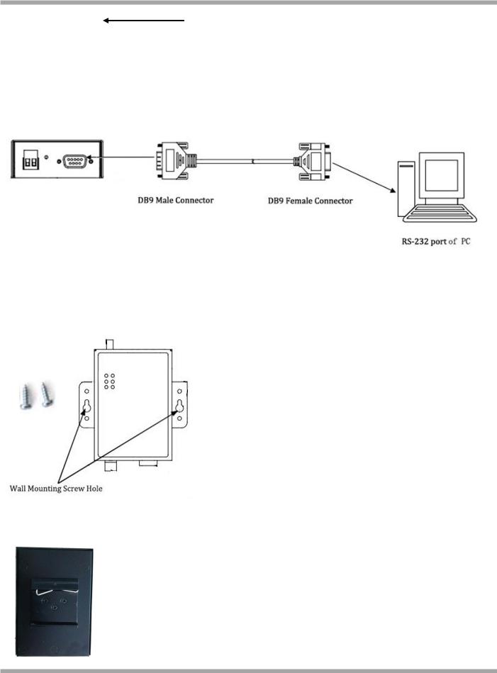
2.6Connect the Gateway to External Device
User can use the serial cable to connect the gateway’s DB9 female connector to external controller / computer.
2.7Mount the Gateway
Use 2 pcs of M3 screw to mount the gateway on the wall.
Or to mount the gateway on a DIN rail, you need three pcs of M3 screws.
RT_UG_M1000 Pro V2_v.2.0.0 |
19.11.2013 |
16 / 69 |
Confidential |
|
|
Robustel GoRugged M1000 Pro V2 User Guide
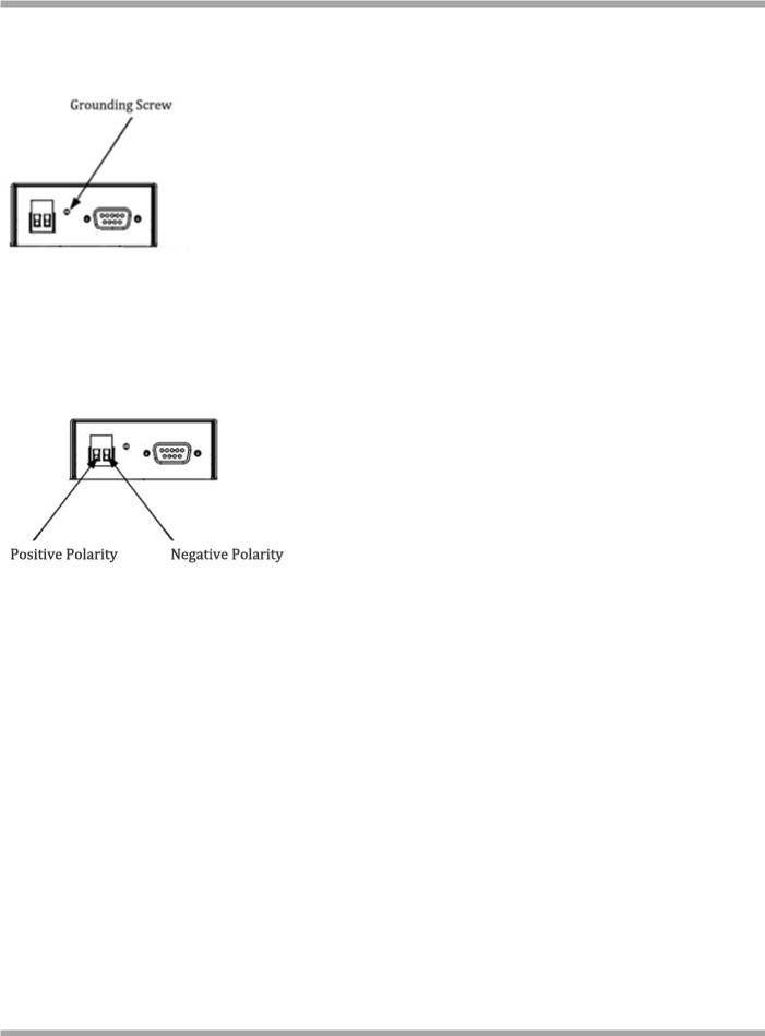
2.8Ground the Gateway
Grounding and wire routing help limit the effects of noise due to electromagnetic interference (EMI). Run the ground connection from the ground screw to the grounding surface prior to connecting devices.
Note: This product is intended to be mounted to a well-grounded mounting surface, such as a metal panel.
2.9Power Supply
The power supply range is 9 to 36VDC.
Note: Please take care about the polarity, and do not make reverse connection.
RT_UG_M1000 Pro V2_v.2.0.0 |
19.11.2013 |
17 / 69 |
Confidential |
|
|

Robustel GoRugged M1000 Pro V2 User Guide
Chapter 3. Operate the Gateway
3.1Working Mode Overview
There are two working modes available in the gateway, please check carefully:
|
Mode |
|
Description |
|
|
|
|
|
When DIP switches to Config Mode, user could use follow functions: |
|
|
|
|
|
1. |
Configure gateway via M1000 Pro V2 Configurator ; |
|
|
Config Mode |
|
2. |
Upgrade firmware. |
|
|
|
|
Serial port parameters is fixed as 115200, 8, None, 1 |
|
|
|
|
|
|
|
|
|
|
|
When DIP switches to Normal Mode, user could use follow functions: |
|
|
|
|
|
1. |
Automatic GPRS/UMTS connection (no AT commands required); |
|
|
|
|
2. |
Wakeup by Timing/Periodical/Call/SMS/Serial Data; |
|
|
Normal Mode |
|
3. |
Transparent data communication or become a Modbus gateway; |
|
|
|
4. |
CSD communication. |
|
|
|
|
|
|
||
|
|
|
5. |
Remote configuration or firmware updating. |
|
|
|
|
Serial port default parameters: 115200, 8, None, 1 |
|
|
|
|
|
|
|
|
3.2M1000 Pro V2 Configurator Overview
M1000 Pro V2 Configurator is a PC-based configuration software tool for managing and configuring Robustel M1000 Pro V2 gateway. With a full graphics mode and Windows-based environment, even first time users will find it easy to learn how to use this new software tool.
M1000 Pro V2 Configurator not only makes configuration easily, but also makes it convenient to carry out “mass deployment” and “pre-configuration”. The most important benefits of using the “M1000 Pro V2 Configurator” utility are:
1.Green software, no need installation;
2.Full graphics mode, easy to learn how to configure the M1000 Pro V2;
3.Configuration profile can be easily stored, and then replicated to other M1000 Pro V2;
4.Easy to upgrade gateway firmware.
Note: M1000 Pro V2 Configurator can be used with Windows 2000/XP/Vista/7 32/64-bit operation systems. If there is any running issue, for example, the Configurator run normally in Win 7 system but fail to run in Windows XP system, please search “Microsoft Visual C++ 2008 Redistributable Package” to download relevant patch and then install the patch.
RT_UG_M1000 Pro V2_v.2.0.0 |
19.11.2013 |
18 / 69 |
Confidential |
|
|

Robustel GoRugged M1000 Pro V2 User Guide
3.2.1 Management via RS-232 port
1.Switch the gateway to “Config Mode”, connect the RS-232 port of the gateway to a host PC, and then power on the gateway.
2.Double click “M1000 Pro V2 Configurator.exe” to start the software.
RT_UG_M1000 Pro V2_v.2.0.0 |
19.11.2013 |
19 / 69 |
Confidential |
|
|
Robustel GoRugged M1000 Pro V2 User Guide
3.Select correct COM port, then click  button. After that you can see the popup windows “Operation Succeed”.
Note: The RS-232 connector uses standard PINOUT. A direct male DB9 to female DB9 cable can be used to connect to a PC’s serial port.
3.2.2 Management via TCP connection
1.Double click “M1000 Pro V2 Configurator.exe” to start the software.
4.Go to tab “Settings” -> “Communication”.
2.Select “TCP” interface and the correct mode in the drop down boxes, and enter the local TCP port. If you choose client mode, you need to enter the remote gateway’s IP address. Then click “OK”.
RT_UG_M1000 Pro V2_v.2.0.0 |
19.11.2013 |
20 / 69 |
Confidential |
|
|
Loading...