

Page 1

Robustel GoRugged M1000 UP
Industrial Cellular USB Modem
for 2G / 3G / 4G Networks
User Guide
Document Name: User Guide
Date: 2015-10-07
Status: Confidential
Doc ID: RT_UG_M1000 UP_v.1.1.1
www.robustel.com
Page 2

Robustel GoRugged M1000 UP User Guide
RT_UG_M1000 UP_v.1.1.1 07.10.2015 1 / 39
About This Document
This document describes the hardware and software of the Robustel GoRugged M1000 UP.
Copyright© Guangzhou Robustel Technologies Co., Limited
All Rights Reserved.
Trademarks and Permissions
Robustel are trademark of Guangzhou Robustel Technologies Co., Limited.
All other trademarks and trade names mentioned in this document are the property of their respective holders.
Disclaimer
No part of this document may be reproduced in any form without the written permission of the copyright owner.
The contents of this document are subject to revision without notice due to continued progress in methodology,
design and manufacturing. Robustel shall have no liability for any error or damage of any kind resulting from the use
of this document.
Technical Support Contact Information
Tel: +86-20-23354618
Fax: +86-20-82321505
E-mail: [email protected]
Web: www.robustel.com
Page 3

Robustel GoRugged M1000 UP User Guide
RT_UG_M1000 UP_v.1.1.1 07.10.2015 2 / 39
Important Notice
Due to the nature of wireless communications, transmission and reception of data can never be guaranteed. Data
may be delayed, corrupted (i.e., have errors) or be totally lost. Although significant delays or losses of data are rare
when wireless devices such as the modem is used in a normal manner with a well-constructed network, the modem
should not be used in situations where failure to transmit or receive data could result in damage of any kind to the
user or any other party, including but not limited to personal injury, death, or loss of property. Robustel accepts no
responsibility for damages of any kind resulting from delays or errors in data transmitted or received using the
modem, or for failure of the modem to transmit or receive such data.
Safety Precautions
General
The modem generates radio frequency (RF) power. When using the modem, care must be taken on safety issues
related to RF interference as well as regulations of RF equipment.
Do not use your modem in aircraft, hospitals, petrol stations or in places where using CELLULAR products is
prohibited.
Be sure that the modem will not be interfering with nearby equipment. For example: pacemakers or medical
equipment. The antenna of the modem should be away from computers, office equipment, home appliance,
etc.
An external antenna must be connected to the modem for proper operation. Only uses approved antenna with
the modem. Please contact authorized distributor on finding an approved antenna.
Always keep the antenna with minimum safety distance of 20 cm or more from human body. Do not put the
antenna inside metallic box, containers, etc.
Note: Some airlines may permit the use of cellular phones while the aircraft is on the ground and the door is open.
Modem may be used at this time.
Using the modem in vehicle
Check for any regulation or law authorizing the use of cellular devices in vehicle in your country before installing
the modem.
The driver or operator of any vehicle should not operate the modem while driving.
Install the modem by qualified personnel. Consult your vehicle distributor for any possible interference of
electronic parts by the modem.
The modem should be connected to the vehicle’s supply system by using a fuse-protected terminal in the
vehicle’s fuse box.
Be careful when the modem is powered by the vehicle’s main battery. The battery may be drained after
extended period.
Protecting your modem
To ensure error-free usage, please install and operate your modem with care. Do remember the following:
Do not expose the modem to extreme conditions such as high humidity/rain, high temperatures, direct sunlight,
caustic / harsh chemicals, dust, or water.
Do not try to disassemble or modify the modem. There is no user serviceable part inside and the warranty
would be void.
Page 4

Robustel GoRugged M1000 UP User Guide
RT_UG_M1000 UP_v.1.1.1 07.10.2015 3 / 39
Do not drop, hit or shake the modem. Do not use the modem under extreme vibrating conditions.
Do not pull the antenna or power supply cable. Attach/detach by holding the connector.
Connect the modem only according to the instruction manual. Failure to do it will void the warranty.
In case of problem, please contact authorized distributor.
Page 5

Robustel GoRugged M1000 UP User Guide
RT_UG_M1000 UP_v.1.1.1 07.10.2015 4 / 39
Regulatory and Type Approval Information
Table 1: Directives
2011/65/EC
Directive 2011/65/EU of the European Parliament and of the Council of 8 June 2011
on the restriction of the use of certain hazardous substances in electrical and
electronic equipment (RoHS)
2012/19/EU
Directive 2012/19/EU the European Parliament and of the Council
of 4 July 2012 on waste electrical and electronic equipment (WEEE)
Table 2: Standards of the Ministry of Information Industry of the People’s Republic of China
SJ/T
11363-2006
“Requirements for Concentration Limits for Certain Hazardous Substances in Electronic Information
Products” (2006-06).
SJ/T
11364-2006
“Marking for Control of Pollution Caused by Electronic Information Products”
(2006-06).
According to the “Chinese Administration on the Control of Pollution caused
by Electronic Information Products” (ACPEIP) the EPUP, i.e., Environmental
Protection Use Period, of this product is 20 years as per the symbol shown here, unless otherwise
marked. The EPUP is valid only as long as the product is operated within the operating limits
described in the Hardware Interface Description.
Please see Table 3 for an overview of toxic or hazardous substances or elements that might be
contained in product parts in concentrations above the limits defined by SJ/T 11363-2006.
Table 3: Toxic or hazardous substances or elements with defined concentration limits
Name of the part
Hazardous substances
(Pb)
(Hg)
(Cd)
(Cr (VI) )
(PBB)
(PBDE)
Metal Parts
o o o o o
o
Circuit Modules
x o o o o o Cables and Cable Assemblies
o o o o o o Plastic and Polymeric parts
o o o o o
o
o:
Indicates that this toxic or hazardous substance contained in all of the homogeneous materials for this part is below
the limit requirement in SJ/T11363-2006.
x:
Indicates that this toxic or hazardous substance contained in at least one of the homogeneous materials for this
part might exceed the limit requirement in SJ/T11363-2006.
Page 6

Robustel GoRugged M1000 UP User Guide
RT_UG_M1000 UP_v.1.1.1 07.10.2015 5 / 39
Revision History
Updates between document versions are cumulative. Therefore, the latest document version contains all updates
made to previous versions.
Release Date
Firmware
Version
Doc Version
Details
2014-01-17
1.0.0
V1.0.0
First Release
2014-05-13
1.0.0
V1.1.0
Update Section: LED Indicator, device
pictures, Safety Precautions, Regulatory
and Type Approval Information, mount the
modem, file format, Sentence Revision,
Regulatory and Type Approval Information
2015-10-07
1.0.0
V1.1.1
Update Section: Cover Image, packing list,
Specification(antenna)
Page 7

Robustel GoRugged M1000 UP User Guide
RT_UG_M1000 UP_v.1.1.1 07.10.2015 6 / 39
Contents
Chapter 1 Product Concept ......................................................................................................................................... 7
1.1 Overview ........................................................................................................................................................ 7
1.2 Packing List ..................................................................................................................................................... 7
1.3 Specifications ................................................................................................................................................. 9
1.4 Dimensions ................................................................................................................................................... 10
Chapter 2 Installation ................................................................................................................................................ 11
2.1 Overview ...................................................................................................................................................... 11
2.2 LED Indicator ................................................................................................................................................ 11
2.3 USB interface ................................................................................................................................................ 12
2.4 Install SIM Card ............................................................................................................................................ 12
2.5 Connect the External Antenna (SMA Type) ................................................................................................. 13
2.6 Connect the Modem to External Device ...................................................................................................... 13
2.7 Mount the Modem ...................................................................................................................................... 13
2.8 Power Supply ............................................................................................................................................... 14
Chapter 3 Operate the Modem ................................................................................................................................ 15
3.1 AT command Set .......................................................................................................................................... 15
3.1.1 Install USB driver............................................................................................................................... 15
3.1.2 Start SecureCRT ................................................................................................................................ 19
3.1.3 AT Command Examples .................................................................................................................... 20
3.2 CSD Connection ............................................................................................................................................ 21
3.2.1 Overview ........................................................................................................................................... 21
3.2.2 Establishing a CSD Connection ......................................................................................................... 21
3.2.3 Answering a CSD Connection ........................................................................................................... 22
3.3 Using Short Message Service ....................................................................................................................... 23
3.3.1 Sending a Short Message .................................................................................................................. 23
3.3.2 Reading a Short Message ................................................................................................................. 24
3.3.3 Deleting a Short Message ................................................................................................................. 25
3.4 Cellular Network Connection ....................................................................................................................... 25
3.4.1 Overview ........................................................................................................................................... 25
3.4.2 Internet Access for PC ....................................................................................................................... 26
Chapter 4 Appendix .................................................................................................................................................. 33
4.1 GSM Alphabet .............................................................................................................................................. 33
4.2 Troubleshooting ........................................................................................................................................... 36
4.2.1 The modem’s LED does not light: ..................................................................................................... 36
4.2.2 The modem keep rebooting all the time: ......................................................................................... 37
4.2.3 Receiving “No Carrier” Message ...................................................................................................... 37
4.3 Terms and Abbreviations ............................................................................................................................. 37
Page 8

Robustel GoRugged M1000 UP User Guide
RT_UG_M1000 UP_v.1.1.1 07.10.2015 7 / 39
Chapter 1 Product Concept
1.1 Overview
Robustel GoRugged M1000 UP is a rugged cellular modem with USB interface and plastic enclosure offering
state-of-the-art 2G (GPRS/EDGE)/3G (HSPA/EV-DO)/4G (LTE) connectivity for machine to machine (M2M)
applications.
Control via AT commands.
USB 2.0 high speed interface allows it to manage and optimize the performances of 3G and 4G high-speed
networks.
LTE downlink/uplink up to 100/50 Mbps.
Antenna diversity for improved fringe performance optional.
Comprehensive SDK and enabling drivers for Linux and Windows.
1 mini USB 2.0 high speed interface.
Wide range input voltages from 6 to 26 VDC and extreme operating temperature.
The plastic enclosure can be mounted on a DIN-rail or on the wall, also with extra ground screw.
1.2 Packing List
Check your package to make certain it contains the following items:
Robustel GoRugged M1000 UP modem x1
3.5mm 2-pin pluggable terminal block for power connector x1
One antenna
Two antennas
or
Page 9

Robustel GoRugged M1000 UP User Guide
RT_UG_M1000 UP_v.1.1.1 07.10.2015 8 / 39
CD with user guide and USB driver x1
Note: Please notify your sales representative if any of the above items are missing or damaged.
Optional accessories (can be purchased separately):
SMA antenna (Stubby antenna or Magnet antenna optional)
The number of SMA antenna depend on the model of M1000 UP, more details please refer to 1.3 Specifications
section.
Mini USB cable x1
Wall Mounting Kit
35mm Din-Rail mounting kit
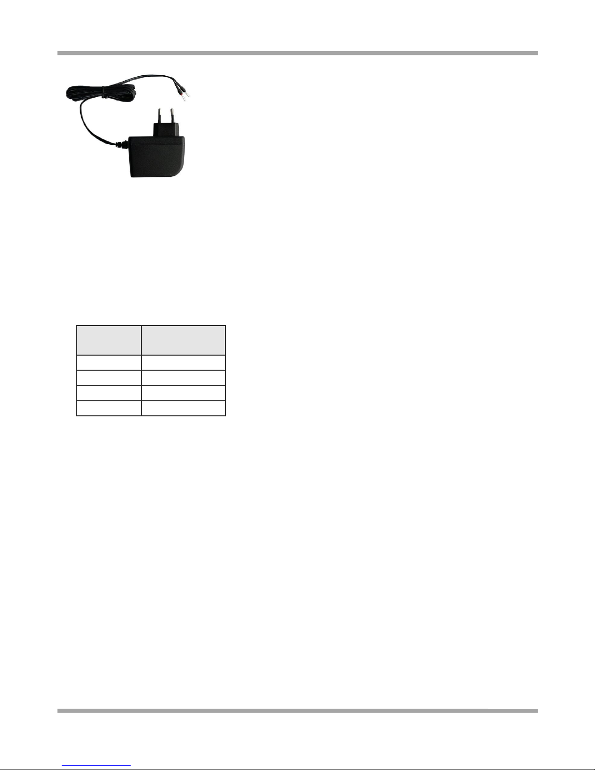
AC/DC Power Supply Adapter (12VDC, 1A) x1
Stubby antenna
Magnet antenna
Page 10
Robustel GoRugged M1000 UP User Guide
RT_UG_M1000 UP_v.1.1.1 07.10.2015 9 / 39
1.3 Specifications
Cellular Interface
Standards: LTE (DL/UL up to 100/50 Mbps), HSPA+/HSUPA/HSDPA/UMTS, EDGE/GPRS, EVDO 450
Frequency: Please refer to “Selection and Ordering Data”
SIM: 1 x (3V & 1.8V)
Antenna Interface: SMA Female
Cellular
interface
the number of
antenna interface
2G GSM
1
3G HSDPA
1
3G HSPA+
2
4G LTE
2
USB Interface
Number of Ports: 1 x mini USB Female
Speed: USB 2.0 High Speed (480 Mbit/s)
ESD Protection: 15KV
GPS (optional for M1000-UP3P and M1000-UP4L)
Protocol: NMEA
Modes: Standalone GPS, Assisted GPS
Drivers
Drivers: Windows 2000/XP/Vista/7/CE, Linux 2.6
System
LED Indicators: RUN
Power Supply and Consumption
Power Supply Interface: 2-pin 3.5mm pluggable terminal block
Input Voltage: 6 to 26 VDC
Power Consumption: Idle: 50-60 mA@12 V
Data Link: 100 to 200 mA (peak)@12 V
Page 11

Robustel GoRugged M1000 UP User Guide
RT_UG_M1000 UP_v.1.1.1 07.10.2015 10 / 39
Physical Characteristics
Housing & Weight: Plastic, 105g
Dimension(L x W x H): 75 x 85 x 28 mm
Installation: 35mm Din-Rail or wall mounting or desktop
Selection and Ordering Data
Model No.
Air Interface
Frequency
Operating Environment
M1000-UP4L
LTE/HSPA+/UMTS/EDGE/GPRS
LTE 800/900/1800/2100/2600 MHz (DL/UL up to
100/50 Mbps)
UMTS 900/2100 MHz, GSM 900/1800/1900 MHz
-25 to 60°C /5 to 95% RH
M1000-UP3P
HSPA+/UMTS/EDGE/GPRS
UMTS 850/900/1900/2100 MHz (DL/UL
14.4/5.76 Mbps) , GSM Quad Band
-40 to 85°C /5 to 95% RH
M1000-UP3H
HSUPA/UMTS/EDGE/GPRS
UMTS 900/2100 MHz (DL/UL 7.2/5.76 Mbps),
GSM 900/1800 MHz
-40 to 85°C /5 to 95% RH
M1000-UP3E
EVDO 450 Rev. B/Rev. A
EVDO 450 MHz (DL/UL 14.7/5.4 Mbps)
-20 to 60°C /5 to 95% RH
M1000-UP
mPCIe interface
w/o module, mPCIe interface
-40 to 85°C /5 to 95% RH
1.4 Dimensions
Page 12
Robustel GoRugged M1000 UP User Guide
RT_UG_M1000 UP_v.1.1.1 07.10.2015 11 / 39
Chapter 2 Installation
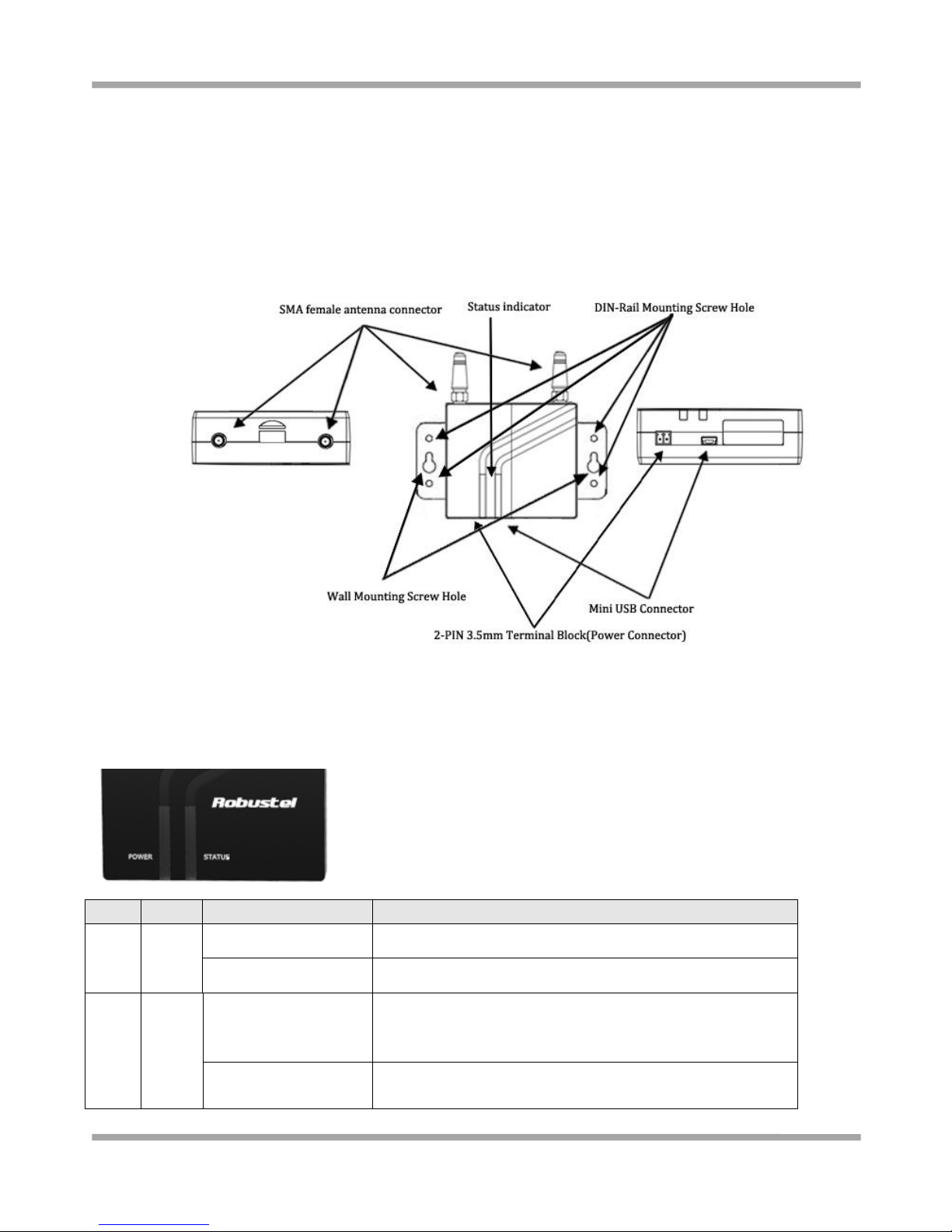
2.1 Overview
2.2 LED Indicator
Name
Color
Status
Description
RUN
Green
On
M1000 UP is powered up.
Off
M1000 UP is powered off.
Status
Green
On
The current network is connected.
Note: only effective on 3G or 4G module, if some 3G or 4G
modules don’t support the LET, the LET won’t light.
Blink every 3 second
The current network is disconnected.
Note: only effective on 3G or 4G module, if some 3G or 4G
Page 13
Robustel GoRugged M1000 UP User Guide
RT_UG_M1000 UP_v.1.1.1 07.10.2015 12 / 39
modules don’t support the LET, the LET won’t light.
Off
The current module is 2G. The LTE will never light.
2.3 USB interface
USB interface can be used for configuration, sending/receiving data and power supply. When USB interface of M1000
UP is used for sending/receiving data as well as power supply, current/voltage output of USB interface which
connects to M1000 UP’s USB interface shall at least reach 1A/5V.
Note: Normally, current/voltage output of PC’s USB 2.0 interface is only 0.5A/5V. So when you use USB interface for
sending/receiving data, you should use power input interface for power supply (please check section 2.8).
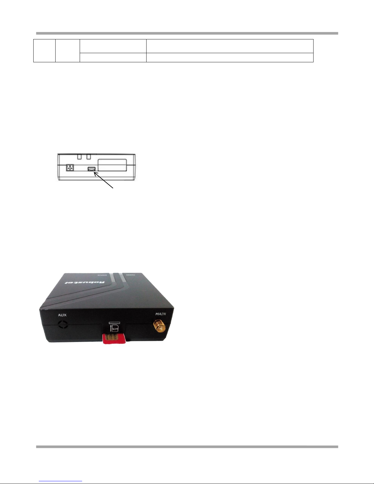
2.4 Install SIM Card
Be sure to insert a SIM card before you use the modem.
Note: A SIM card set with PIN code cannot be used normally in the modem without the correct PIN code.
Make sure to disconnect the adapter and switch off your modem before inserting or removing your SIM/USIM card.
Inserting SIM Card
1. Make sure your adapter is disconnected.
2. Insert the SIM card, and you need press the SIM card with your fingers until you hear “a cracking sound”.
Removing SIM card
1. Make sure your adapter is disconnected.
2. Press the SIM card until you hear “a cracking sound”, then the SIM card will pop up to be pulled out.
Note:
1. Don’t touch the metal surface of the SIM card in case information in the card is lost or destroyed.
USB
Page 14
Robustel GoRugged M1000 UP User Guide
RT_UG_M1000 UP_v.1.1.1 07.10.2015 13 / 39
2. Don’t bend or scratch your SIM card. Keep the card away from electricity and magnetism.
3. Make sure to disconnect the power source from your modem before inserting and removing your SIM card.
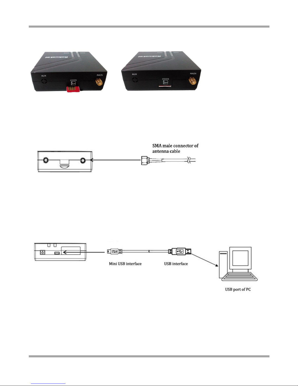
2.5 Connect the External Antenna (SMA Type)
Connect this to an external antenna with SMA male connector. Make sure the antenna is within correct frequency
range as your GSM/GPRS/UMTS/HSPA operator with impedance of 50ohm, and connector is screwed tightly.
2.6 Connect the Modem to External Device
User can use the USB cable to connect the modem’s Mini USB Connector to external slave devices / controller /
computer.
Note: User needs to install relevant USB driver to PC, which you can find out in the CD.
2.7 Mount the Modem
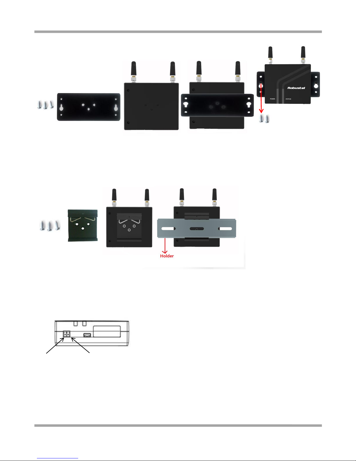
Two ways of mounting the modem
1. Use 3 pcs of M3 screw to mount the Modem on the Wall mounting Kit.
And then use 2 pcs of M3 screw to mount the Wall mounting Kit on the wall.
Screw tightly
Page 15
Robustel GoRugged M1000 UP User Guide
RT_UG_M1000 UP_v.1.1.1 07.10.2015 14 / 39
2. Mount the modem on a DIN rail with 3 pcs of M3 screws, and then hang the DIN-Rail on the holder.
You need to choose a standard holder.
2.8 Power Supply
The power supply range is 6 to 26 VDC.
Note: Please take care about the polarity, and do not make reverse connection.
Negative Polarity
Positive Polarity
Page 16
Robustel GoRugged M1000 UP User Guide
RT_UG_M1000 UP_v.1.1.1 07.10.2015 15 / 39
Chapter 3 Operate the Modem
3.1 AT command Set
We can operate and configure M1000 UP via AT commands through mini USB port. This chapter will introduce how
to install USB driver and AT command examples while configuring M1000 UP.
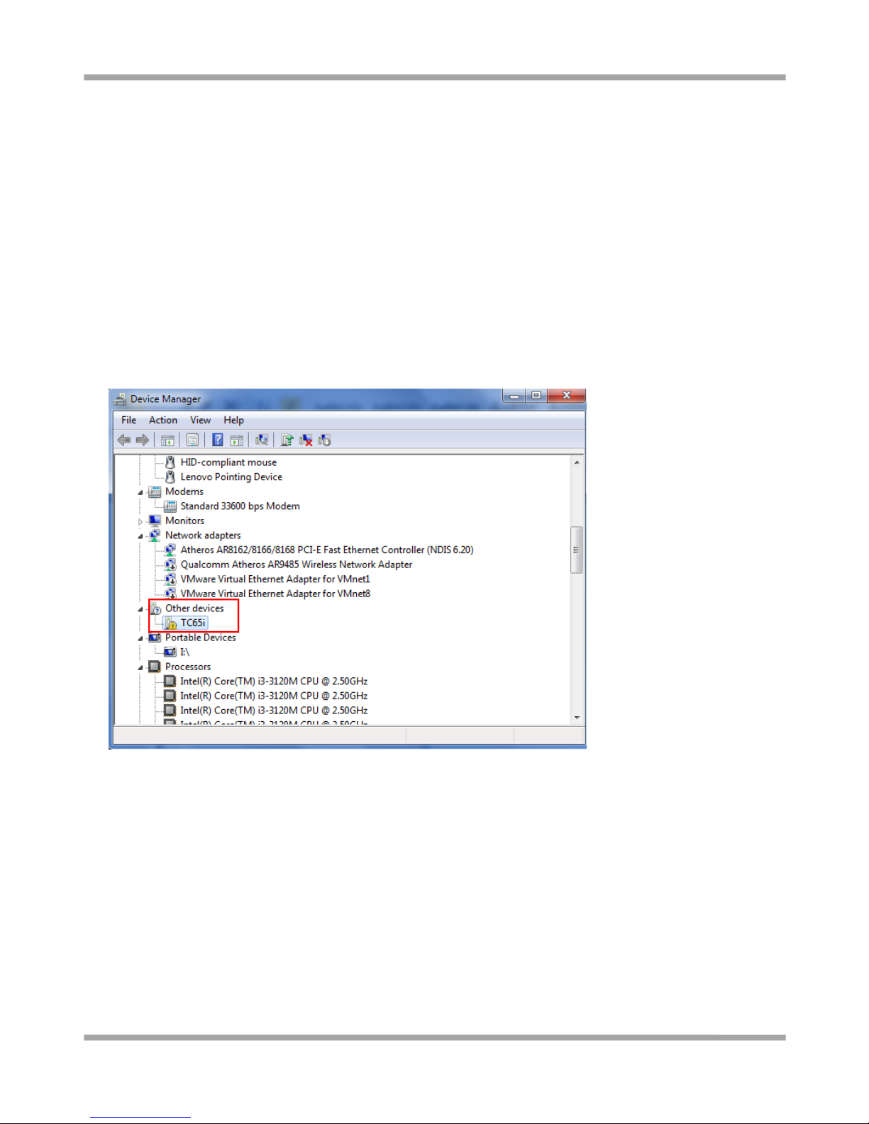
3.1.1 Install USB driver
1. In the Control Panel, when you connect USB cable to PC, it will pop up tab Other devices and show M1000 UP’s
module version.
Page 17
Robustel GoRugged M1000 UP User Guide
RT_UG_M1000 UP_v.1.1.1 07.10.2015 16 / 39
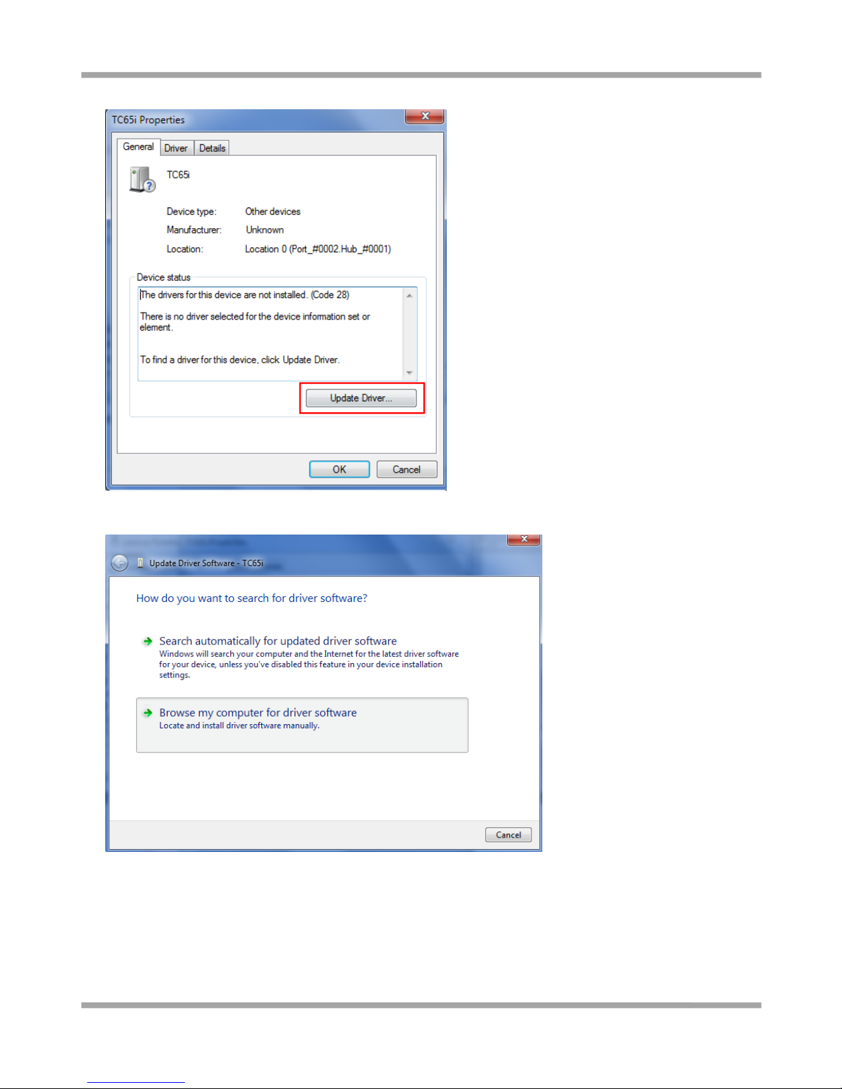
2. Right-click to enter Properties and then click Update Driver.
3. Click Browse my computer for driver software.
Page 18
Robustel GoRugged M1000 UP User Guide
RT_UG_M1000 UP_v.1.1.1 07.10.2015 17 / 39
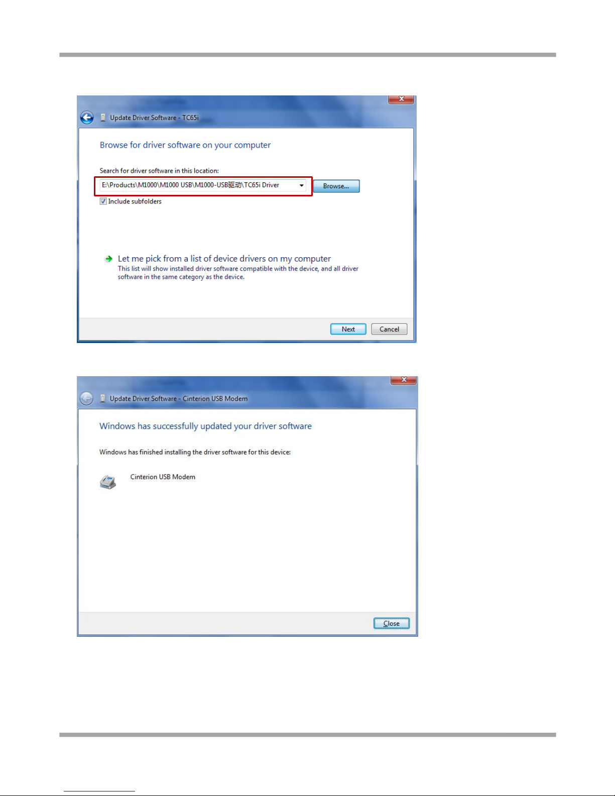
4. Click Browse to locate to position of the USB driver (you can find out relevant USB driver in the CD), then click
Next.
5. After succeeding to install the USB driver, it will pop up the following window.
Page 19
Robustel GoRugged M1000 UP User Guide
RT_UG_M1000 UP_v.1.1.1 07.10.2015 18 / 39
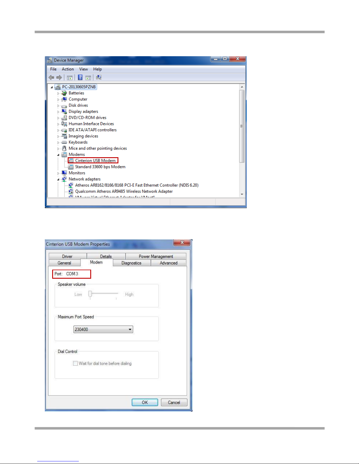
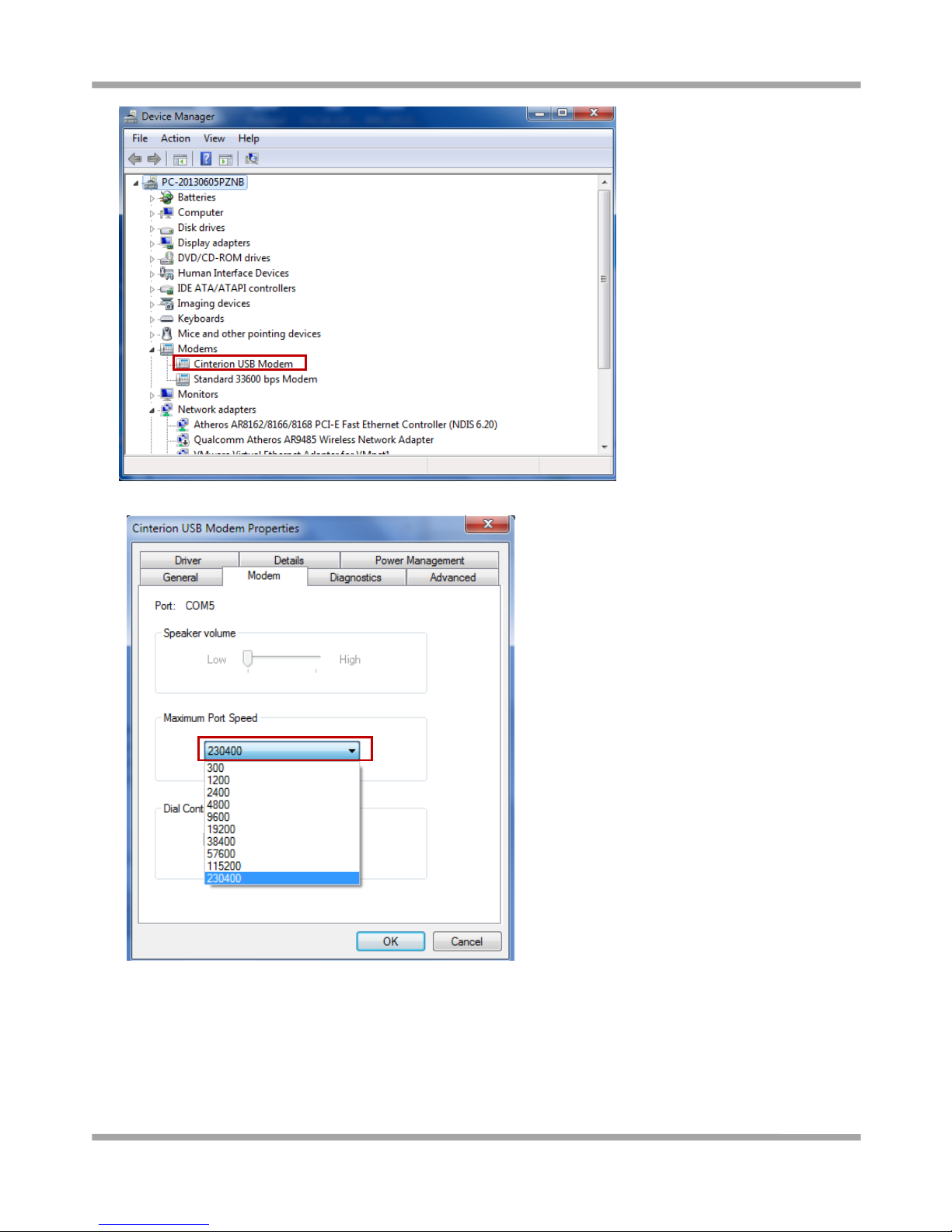
6. A simulated virtual COM port which binds to the USB interface of M1000 UP will open after USB driver has been
installed. Please check “Device Manager” -> “Modems”.
7. Select the USB modem and right-click to enter “Properties”. In tab “Modem”, you will find that there is simulated
COM port which serial software such as secureCRT needs to connect to.
Page 20
Robustel GoRugged M1000 UP User Guide
RT_UG_M1000 UP_v.1.1.1 07.10.2015 19 / 39
3.1.2 Start SecureCRT
We can enter AT commands to configure M1000 UP from serial software such as secureCRT, you can download this
software via link: https://app.box.com/s/arkn6xk1asgs1myvuuie.
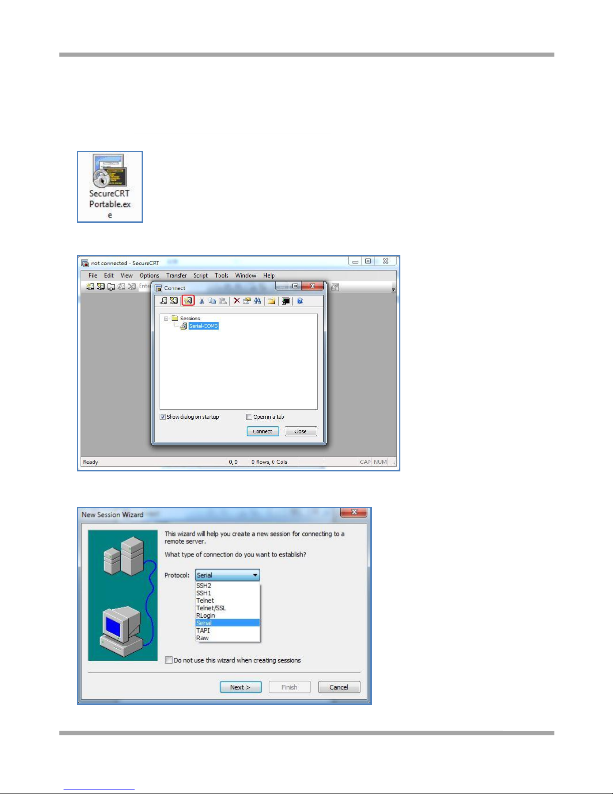
1. Double click SecureCRT Potable.exe .
2. File->Connect->New Session
3. Select Protocol as “Serial”.
Page 21
Robustel GoRugged M1000 UP User Guide
RT_UG_M1000 UP_v.1.1.1 07.10.2015 20 / 39
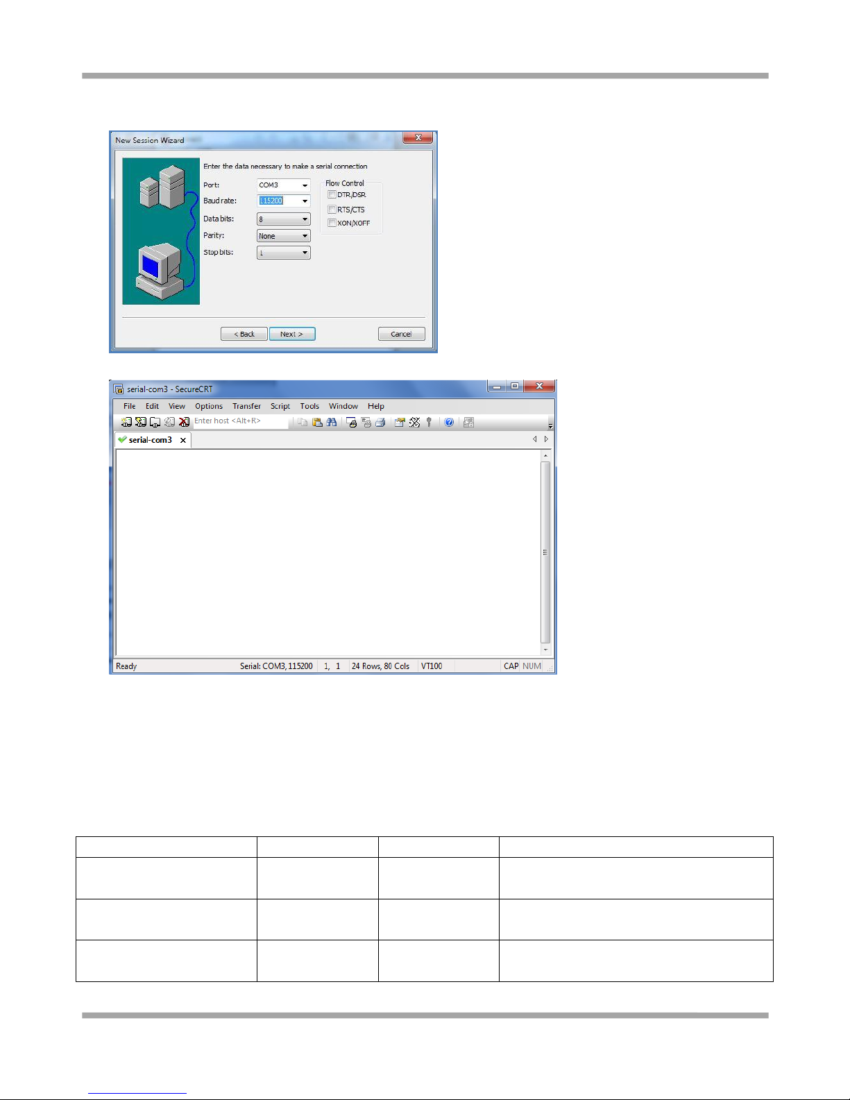
4. Select the simulated COM port and match the parameters as below, click the “Next” button to finish this session.
Note: You need to disable “RTS/CTS.
3.1.3 AT Command Examples
M1000 UP supports the guidelines known as the “AT Command Set.” AT Command Set is the industry standard
line-oriented command language used to communicate with the modem.
Followings are examples of some AT commands. Please refer to the AT command guide for a full description.
Description
AT commands
Modem response
Comments
Modem acknowledgement
AT
OK
Responding OK indicates that the modem is
ready.
Receiving signal strength
AT+CSQ
+CSQ: 19,99
The first parameter has to be at least 15 for
normal communication.
Query current PIN status
AT+CPIN?
+CPIN: READY
SIM card is correctly inserted and modem is
not pending for any password
Page 22
Robustel GoRugged M1000 UP User Guide
RT_UG_M1000 UP_v.1.1.1 07.10.2015 21 / 39
+CPIN: SIM PIN
PIN1 is required
+CPIN: SIM PUK
PUK1 is required
Saves parameters in
non-volatile memory
AT&W
OK
The configuration settings are stored.
3.2 CSD Connection
3.2.1 Overview
A Circuit-Switched Data Connection makes the wireless modem work in a manner similar to a regular analog modem.
CSD (Circuit Switched Data) is the original form of data transmission developed for cellular systems. By using a single
radio time slot, CSD is able to deliver 9.6 to 14.4 kbit/s data transmission to both the CELLULAR Network and PSTN
Switching Subsystem through direct calls. Most of the time, it is initiated by standard AT commands. Using the
modem to access remote devices by CSD is often more convenient than installing cables and data lines. Data
collection and monitoring will be more flexible since CSD can be used for applications that are hard to wire or hard
to access.
Note: Ensure that your SIM card has the CSD Service activated. For most regions, you must apply to your mobile
service provider to receive this service.
3.2.2 Establishing a CSD Connection
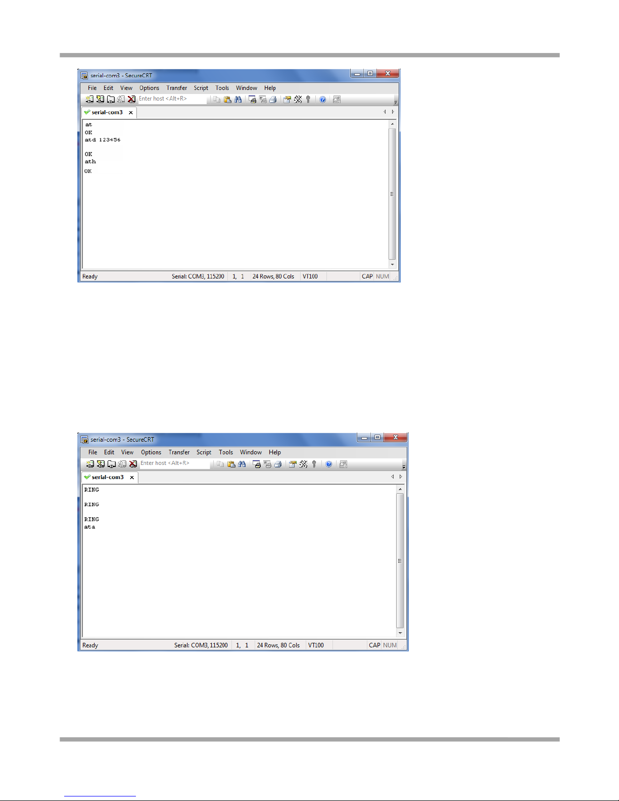
1. Start SecureCRT with serial parameters 115200,8,n,1.
2. Type ATD <phone number> and press Enter to establish a CSD connection. (e.g. ATD 123456, in which 123456 is
the phone number.)
3. After remote side answering the CSD call, then the CSD connection has been established successfully.
4. To close the CSD connection, type +++. The modem will respond with OK to indicate that you have already
switched back to the command mode. It means you can enter AT commands again via SecureCRT.
5. Type ATH and press Enter to disconnect.
Page 23
Robustel GoRugged M1000 UP User Guide
RT_UG_M1000 UP_v.1.1.1 07.10.2015 22 / 39
Note:
+++ is the escape sequence, and ATH is the hang-up command.
For international calls, the local international prefix does not need to be set, but does need to be replaced by
the + character. E.g., you would type ATD+86123456, in which +86 is the country code.
3.2.3 Answering a CSD Connection
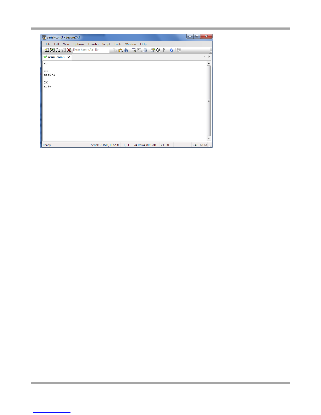
1. When secureCRT displays the RING response, type ATA, and press Enter.
2. In the secureCRT window, type ATS0=x and press Enter. For x, substitute the number of rings that the modem
should receive before answering the call. For example, to answer after the first ring, type ATS0=1.
3. Type AT&W and press Enter.
Page 24
Robustel GoRugged M1000 UP User Guide
RT_UG_M1000 UP_v.1.1.1 07.10.2015 23 / 39
4. To close the CSD connection, type +++. The modem will respond with OK to indicate that you have already
switched back to the command mode.
5. Type ATH and press Enter to disconnect.
3.3 Using Short Message Service
Cellular technology offers the benefit of using SMS (short message service) as an easy way to communicate over the
mobile network.
The following topics are covered in this chapter:
1. Sending a Short Message
2. Reading a Short Message
3. Deleting a Short Message
3.3.1 Sending a Short Message
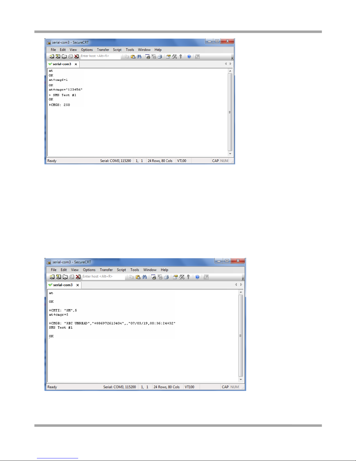
1. Type AT+CMGF=1 and press Enter.
2. Type AT+CMGS=“<phone number>” and press Enter. The terminal will automatically move to the next line,
which starts with >. Type your message on the right of the >.
3. Enter Ctrl + Z deliver the message.
Page 25
Robustel GoRugged M1000 UP User Guide
RT_UG_M1000 UP_v.1.1.1 07.10.2015 24 / 39
Note: AT+CMGF=1 sets the SMS to Text mode.
3.3.2 Reading a Short Message
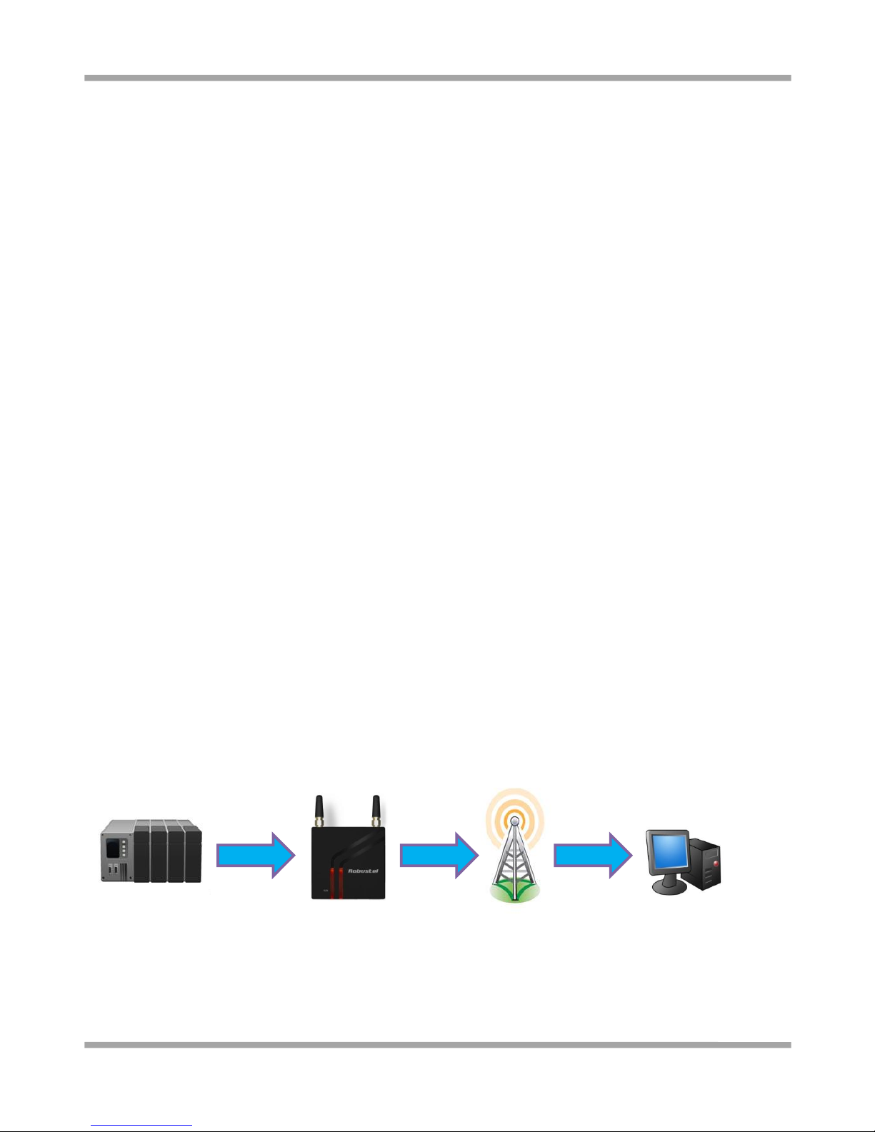
1. Type AT+CMGF=1 and then press Enter.
2. Type AT+CNMI=2,1 and then press Enter.
3. When a short message is received, the modem will show the storage number of the message after “+CMIT: “SM”,
x” (where the x is the storage number).
4. Type AT+CMGR=x to read the message.
5. In the example shown below, the x=5 means that the message is stored in the 5th storage location.
Page 26
Robustel GoRugged M1000 UP User Guide
RT_UG_M1000 UP_v.1.1.1 07.10.2015 25 / 39
3.3.3 Deleting a Short Message
Type AT+CMGD=x,n and then press Enter.
This is where x represents one of the following options:
“REC UNREAD” Shows received unread messages.
“REC READ” Shows received read messages.
“STO UNSENT” Shows stored unsent messages.
“STO SENT” Shows stored sent messages.
“ALL” Shows messages.
This is where n represents one of the following options:
0 Delete message at location <include the index number>
1 Delete all READ messages.
2 Delete all READ and SENT messages.
3 Delete all READ, SENT, and UNSENT messages.
4 Delete ALL messages. “REC UNREAD” Shows received unread messages.
Note: Refer to the Documentation and Software CD / AT_Commands / AT_Commands.pdf for further detail
commands information using SMS.
3.4 Cellular Network Connection
3.4.1 Overview
A cellular network is a wireless network distributed over land areas called cells, each served by at least one
fixed-location transceiver, known as a cell site or base station. We can use our mobile phones or PCs to connect to
cellular network basing on 2G (GPRS/EDGE)/3G (HSPA/EV-DO)/4G (LTE) technology.
M1000 UP offers state-of-the-art 2G (GPRS/EDGE)/3G (HSPA/EV-DO)/4G (LTE) connectivity for machine to machine
(M2M) applications, it can provide cellular network connection for end-user devices such as PCs, embedded
computers, and PLCs that are PPP-enabled and can be easily connected to the cellular network and the Internet.
Cellular Network:
2G/3G/4G
Page 27
Robustel GoRugged M1000 UP User Guide
RT_UG_M1000 UP_v.1.1.1 07.10.2015 26 / 39
3.4.2 Internet Access for PC
The modem can use Windows DUN (Dial-up Networking) to provide the Internet access through the cellular network.
Instructions are described in the following chapters.
Note: The specific steps may vary depending on your version of Windows and your Windows settings. Following steps
are basing on Windows 7.
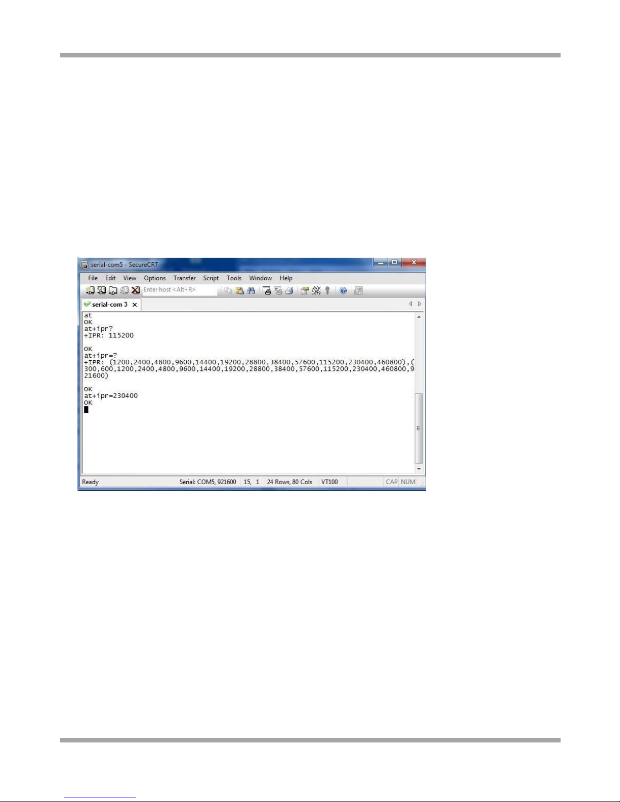
Change baudrate of modem
1. You can set baudrate of the simulated COM port to highest speed following the diagram below. The highest
speed of the simulated port varies from different module of M1000 UP, you can use AT command “AT+IPR=?” to
check baudrate details. In this document, we use AT command “AT+IPR=230400” to set baudrate of the simulated
COM port to 230400.
Set Maximum Port Speed
1. In the Control Panel, Select the USB modem in tab Device Manager -> Modems -> XXX USB modem.
Page 28
Robustel GoRugged M1000 UP User Guide
RT_UG_M1000 UP_v.1.1.1 07.10.2015 27 / 39
2. Right-click to enter Properties. You can select the maxumum port speed as 230400 in tab Modem.
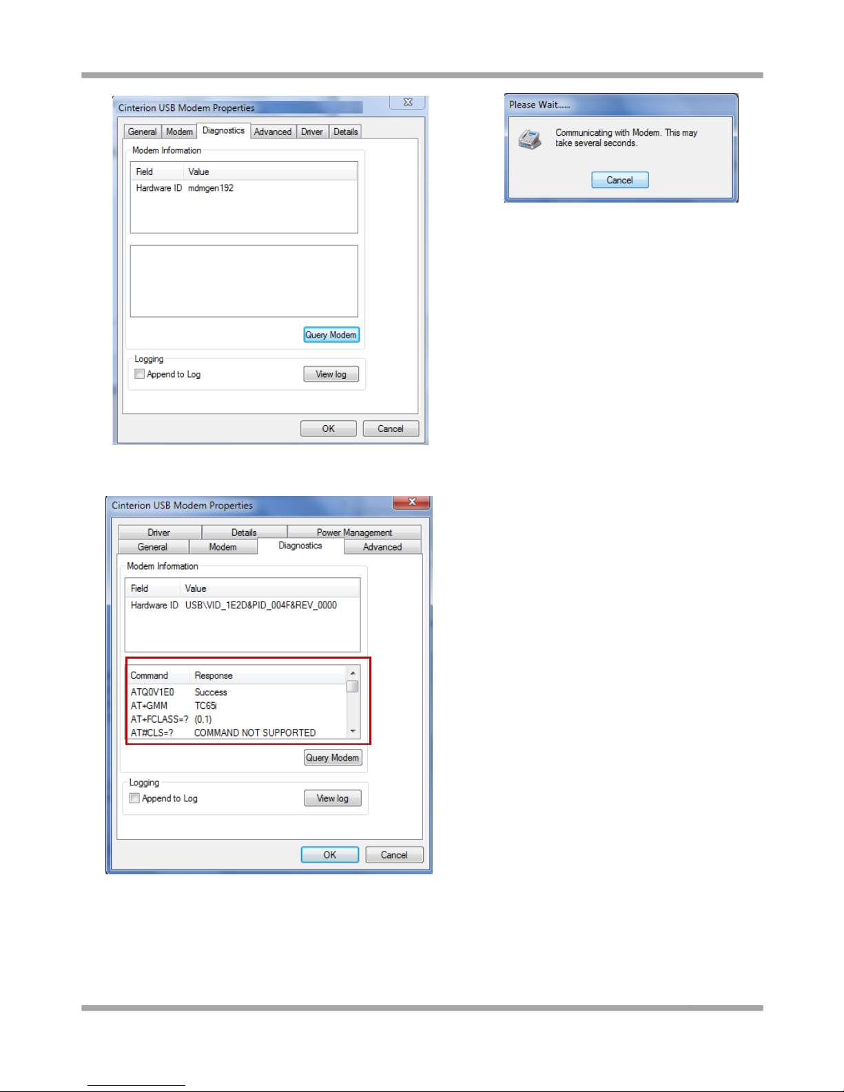
Modem Diagnostics
Follow these steps to verify that the modem is installed properly and has been activated.
1. Click the Diagnostics tab, and then click Query Modem. After that it will popup “Please Wait” window. This
process will almost take you 4 seconds.
Page 29
Robustel GoRugged M1000 UP User Guide
RT_UG_M1000 UP_v.1.1.1 07.10.2015 28 / 39
2. If the query is successful, both commands sent to the modem and responses from the modem will be displayed.
Click OK to close the window.
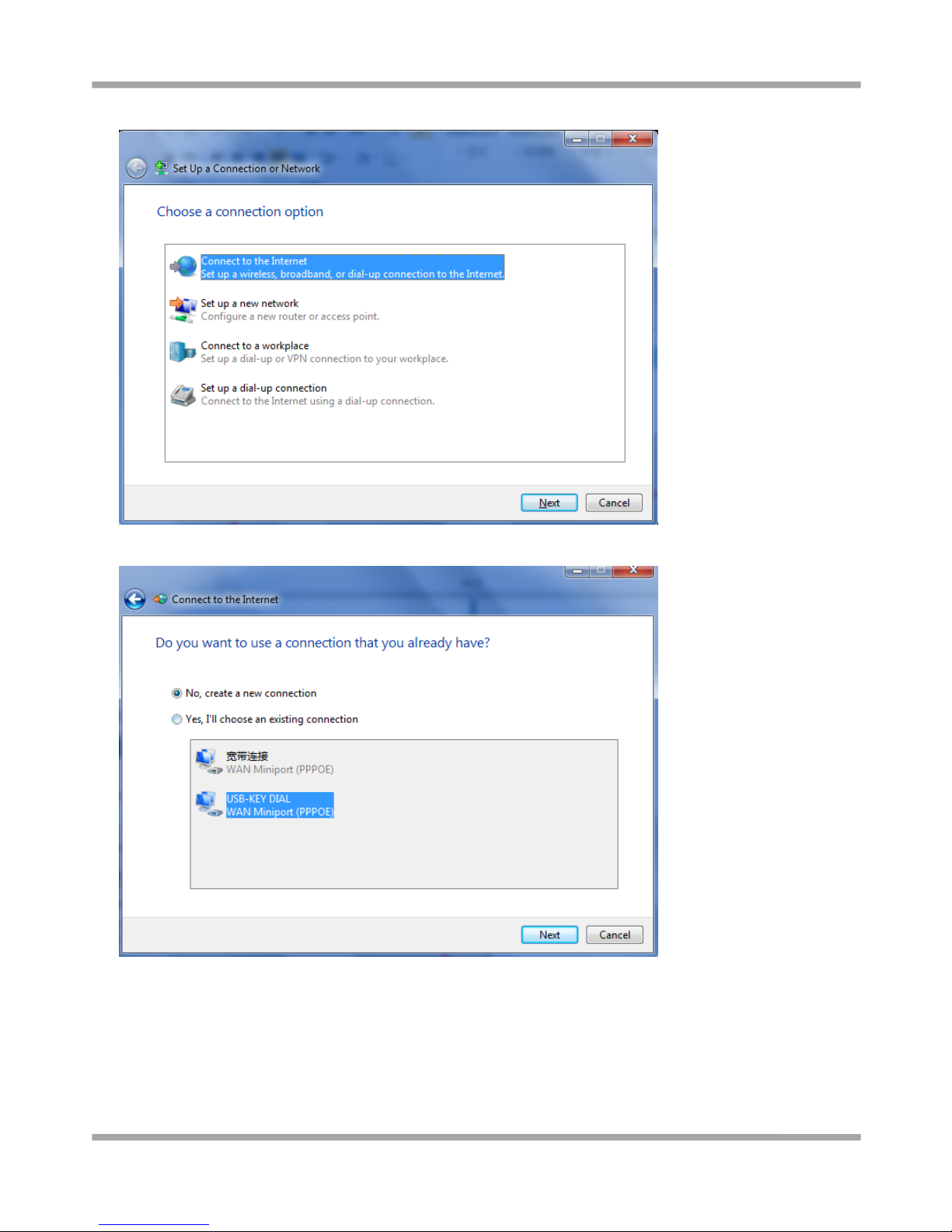
Adding Windows DUN
Follow these steps to add Windows Dial-up Networking.
1. In the Control Panel, open Network and Sharing Center, and then click Set up a new connection or network.
2. When the Set Up a Connection or Network window opens, select the Connect to the Internet option, and then
Page 30
Robustel GoRugged M1000 UP User Guide
RT_UG_M1000 UP_v.1.1.1 07.10.2015 29 / 39
click Next.
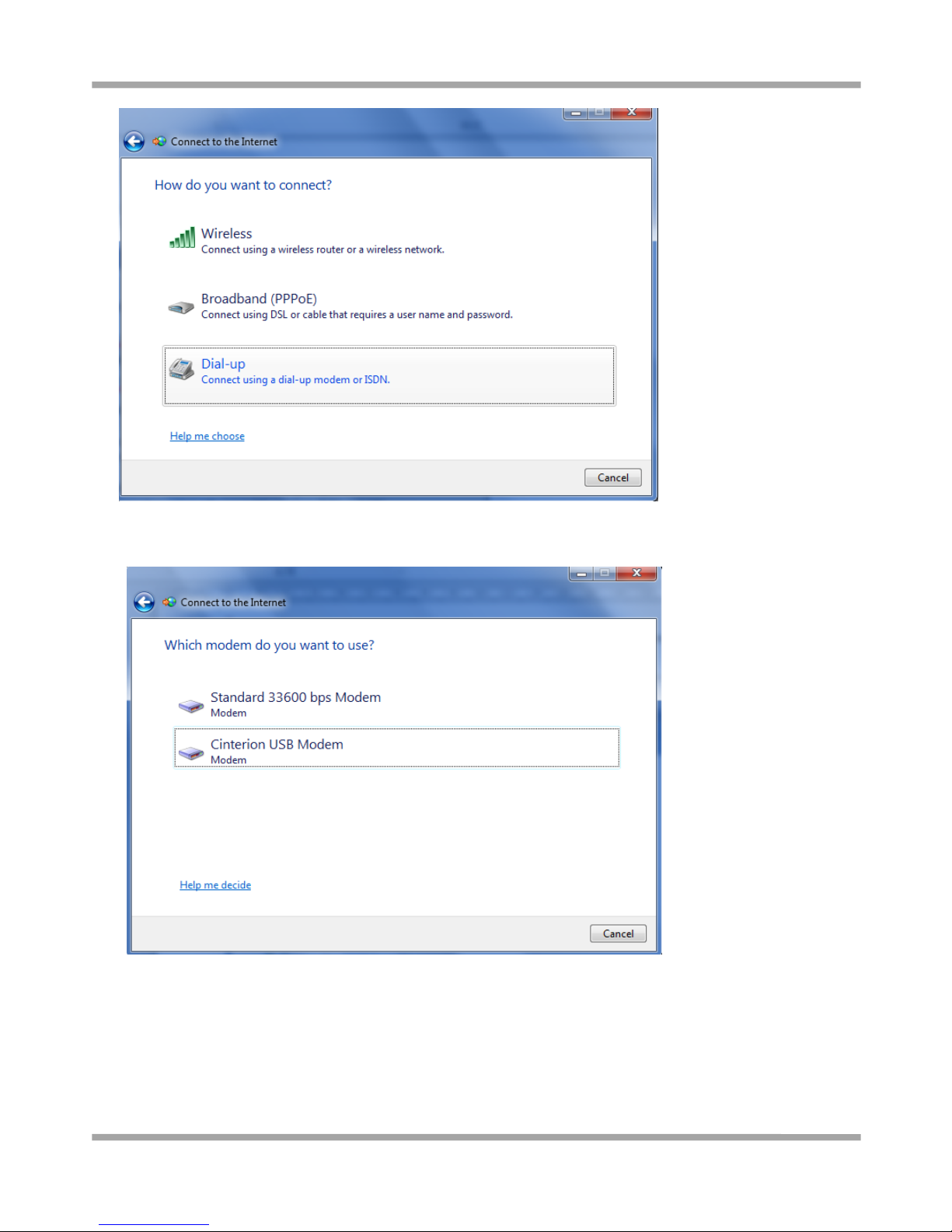
3. Select the No, create a new connection option, and then click Next.
4. Select the Dial-up option.
Page 31
Robustel GoRugged M1000 UP User Guide
RT_UG_M1000 UP_v.1.1.1 07.10.2015 30 / 39
5. Select the correct USB Modem which is shown as the same as Device Manager -> Modems -> XXX USB modem.
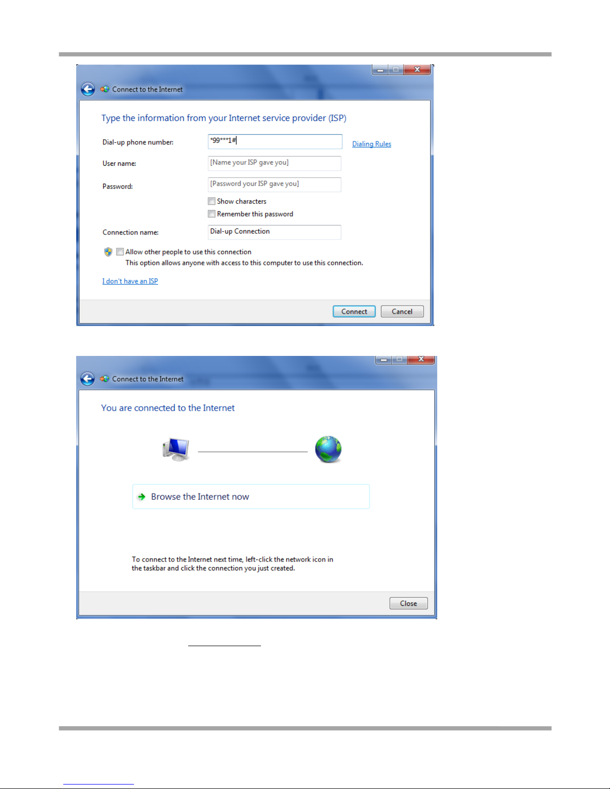
6. Type *99***1# in the Phone number text input box, and type the User name and Password in the appropriate
text boxes, and then click Connect.
Note: User Name and Password is used for cellular dial-up connection, you can check with local ISP whether you
need to enter and what you need to enter.
Page 32
Robustel GoRugged M1000 UP User Guide
RT_UG_M1000 UP_v.1.1.1 07.10.2015 31 / 39
7. After dial up successfully, it will show window below.
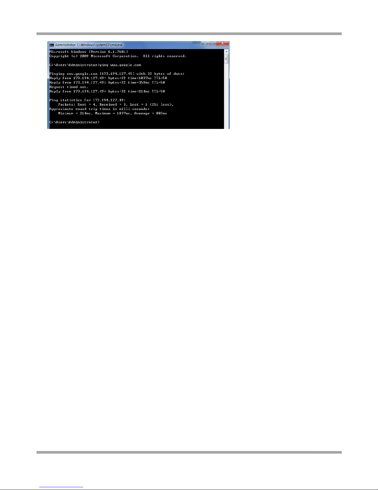
8. Also you can try to ping to www.google.com to check whether GPRS connection has been established.
Page 33
Robustel GoRugged M1000 UP User Guide
RT_UG_M1000 UP_v.1.1.1 07.10.2015 32 / 39
Page 34
Robustel GoRugged M1000 UP User Guide
RT_UG_M1000 UP_v.1.1.1 07.10.2015 33 / 39
Chapter 4 Appendix
4.1 GSM Alphabet
Standard SMS can contain 160 characters. However, the characters typed must be part of the so-called 7-bit default
alphabet as specified by GSM 3.38. You can see in the table below that this alphabet contains all ASCII characters and
some accented characters.
For example, u umlaut (ü) and e with grave (è), are in this set. Please study the table below to have a complete
overview. Using any character not in this set, will make the SMS a Unicode SMS and limit the length of the SMS to 70
characters.
Note: a few characters actually count as two characters. These characters are:
{}[]~|\ and the Euro symbol: €
You can also see that in the table below in the hex column. These characters need to be escaped.
Below is the 7 bit default alphabet as specified by GSM 03.38. The corresponding ISO-8859-1 decimal codes are
shown in the rightmost column. Note that the euro sign (€) is also included.
Hex
Dec
Character name
Character
ISO-8859-1 DEC
0×00
0
COMMERCIAL AT
@
64
0×01
1
POUND SIGN
£
163
0×02
2
DOLLAR SIGN
$
36
0×03
3
YEN SIGN
¥
165
0×04
4
LATIN SMALL LETTER E WITH GRAVE
è
232
0×05
5
LATIN SMALL LETTER E WITH ACUTE
é
233
0×06
6
LATIN SMALL LETTER U WITH GRAVE
ù
249
0×07
7
LATIN SMALL LETTER I WITH GRAVE
ì
236
0×08
8
LATIN SMALL LETTER O WITH GRAVE
ò
242
0×09
9
LATIN CAPITAL LETTER C WITH CEDILLA
Ç
199
0×0A
10
LINE FEED
10
0×0B
11
LATIN CAPITAL LETTER O WITH STROKE
Ø
216
0×0C
12
LATIN SMALL LETTER O WITH STROKE
ø
248
0×0D
13
CARRIAGE RETURN
13
0×0E
14
LATIN CAPITAL LETTER A WITH RING ABOVE
Å
197
0×0F
15
LATIN SMALL LETTER A WITH RING ABOVE
å
229
0×10
16
GREEK CAPITAL LETTER DELTA
Δ
0×11
17
LOW LINE
_
95
0×12
18
GREEK CAPITAL LETTER PHI
Φ 0×13
19
GREEK CAPITAL LETTER GAMMA
Γ 0×14
20
GREEK CAPITAL LETTER LAMBDA
Λ 0×15
21
GREEK CAPITAL LETTER OMEGA
Ω 0×16
22
GREEK CAPITAL LETTER PI
Π
0×17
23
GREEK CAPITAL LETTER PSI
Ψ
Page 35
Robustel GoRugged M1000 UP User Guide
RT_UG_M1000 UP_v.1.1.1 07.10.2015 34 / 39
0×18
24
GREEK CAPITAL LETTER SIGMA
Σ 0×19
25
GREEK CAPITAL LETTER THETA
Θ 0×1A
26
GREEK CAPITAL LETTER XI
Ξ 0×1B
27
ESCAPE TO EXTENSION TABLE
0×1B0A
27 10
FORM FEED
12
0×1B14
27 20
CIRCUMFLEX ACCENT
^
94
0×1B28
27 40
LEFT CURLY BRACKET
{
123
0×1B29
27 41
RIGHT CURLY BRACKET
}
125
0×1B2F
27 47
REVERSE SOLIDUS (BACKSLASH)
\
92
0×1B3C
27 60
LEFT SQUARE BRACKET
[
91
0x1B3D
27 61
TILDE
~
126
0x1B3E
27 62
RIGHT SQUARE BRACKET
]
93
0×1B40
27 64
VERTICAL BAR
|
124
0×1B65
27 101
EURO SIGN
€
164 (ISO-8859-15)
0×1C
28
LATIN CAPITAL LETTER AE
Æ
198
0×1D
29
LATIN SMALL LETTER AE
æ
230
0×1E
30
LATIN SMALL LETTER SHARP S (German)
ß
223
0×1F
31
LATIN CAPITAL LETTER E WITH ACUTE
É
201
0×20
32
SPACE
32
0×21
33
EXCLAMATION MARK
!
33
0×22
34
QUOTATION MARK
“
34
0×23
35
NUMBER SIGN
#
35
0×24
36
CURRENCY SIGN
¤
164 (ISO-8859-1)
0×25
37
PERCENT SIGN
%
37
0×26
38
AMPERSAND
&
38
0×27
39
APOSTROPHE
‘
39
0×28
40
LEFT PARENTHESIS
(
40
0×29
41
RIGHT PARENTHESIS
)
41
0×2A
42
ASTERISK
*
42
0×2B
43
PLUS SIGN
+
43
0×2C
44
COMMA
,
44
0×2D
45
HYPHEN-MINUS
-
45
0×2E
46
FULL STOP
.
46
0×2F
47
SOLIDUS (SLASH)
/
47
0×30
48
DIGIT ZERO
0
48
0×31
49
DIGIT ONE
1
49
0×32
50
DIGIT TWO
2
50
0×33
51
DIGIT THREE
3
51
0×34
52
DIGIT FOUR
4
52
0×35
53
DIGIT FIVE
5
53
0×36
54
DIGIT SIX
6
54
0×37
55
DIGIT SEVEN
7
55
0×38
56
DIGIT EIGHT
8
56
Page 36
Robustel GoRugged M1000 UP User Guide
RT_UG_M1000 UP_v.1.1.1 07.10.2015 35 / 39
0×39
57
DIGIT NINE
9
57
0×3A
58
COLON
:
58
0×3B
59
SEMICOLON
;
59
0×3C
60
LESS-THAN SIGN
<
60
0×3D
61
EQUALS SIGN
=
61
0×3E
62
GREATER-THAN SIGN
>
62
0×3F
63
QUESTION MARK
?
63
0×40
64
INVERTED EXCLAMATION MARK
¡
161
0×41
65
LATIN CAPITAL LETTER A
A
65
0×42
66
LATIN CAPITAL LETTER B
B
66
0×43
67
LATIN CAPITAL LETTER C
C
67
0×44
68
LATIN CAPITAL LETTER D
D
68
0×45
69
LATIN CAPITAL LETTER E
E
69
0×46
70
LATIN CAPITAL LETTER F
F
70
0×47
71
LATIN CAPITAL LETTER G
G
71
0×48
72
LATIN CAPITAL LETTER H
H
72
0×49
73
LATIN CAPITAL LETTER I
I
73
0×4A
74
LATIN CAPITAL LETTER J
J
74
0×4B
75
LATIN CAPITAL LETTER K
K
75
0×4C
76
LATIN CAPITAL LETTER L
L
76
0×4D
77
LATIN CAPITAL LETTER M
M
77
0×4E
78
LATIN CAPITAL LETTER N
N
78
0×4F
79
LATIN CAPITAL LETTER O
O
79
0×50
80
LATIN CAPITAL LETTER P
P
80
0×51
81
LATIN CAPITAL LETTER Q
Q
81
0×52
82
LATIN CAPITAL LETTER R
R
82
0×53
83
LATIN CAPITAL LETTER S
S
83
0×54
84
LATIN CAPITAL LETTER T
T
84
0×55
85
LATIN CAPITAL LETTER U
U
85
0×56
86
LATIN CAPITAL LETTER V
V
86
0×57
87
LATIN CAPITAL LETTER W
W
87
0×58
88
LATIN CAPITAL LETTER X
X
88
0×59
89
LATIN CAPITAL LETTER Y
Y
89
0×5A
90
LATIN CAPITAL LETTER Z
Z
90
0×5B
91
LATIN CAPITAL LETTER A WITH DIAERESIS
Ä
196
0×5C
92
LATIN CAPITAL LETTER O WITH DIAERESIS
Ö
214
0×5D
93
LATIN CAPITAL LETTER N WITH TILDE
Ñ
209
0×5E
94
LATIN CAPITAL LETTER U WITH DIAERESIS
Ü
220
0×5F
95
SECTION SIGN
§
167
0×60
96
INVERTED QUESTION MARK
¿
191
0×61
97
LATIN SMALL LETTER A
a
97
0×62
98
LATIN SMALL LETTER B
b
98
0×63
99
LATIN SMALL LETTER C
c
99
Page 37
Robustel GoRugged M1000 UP User Guide
RT_UG_M1000 UP_v.1.1.1 07.10.2015 36 / 39
0×64
100
LATIN SMALL LETTER D
d
100
0×65
101
LATIN SMALL LETTER E
e
101
0×66
102
LATIN SMALL LETTER F
f
102
0×67
103
LATIN SMALL LETTER G
g
103
0×68
104
LATIN SMALL LETTER H
h
104
0×69
105
LATIN SMALL LETTER I
i
105
0×6A
106
LATIN SMALL LETTER J
j
106
0×6B
107
LATIN SMALL LETTER K
k
107
0×6C
108
LATIN SMALL LETTER L
l
108
0×6D
109
LATIN SMALL LETTER M
m
109
0×6E
110
LATIN SMALL LETTER N
n
110
0×6F
111
LATIN SMALL LETTER O
o
111
0×70
112
LATIN SMALL LETTER P
p
112
0×71
113
LATIN SMALL LETTER Q
q
113
0×72
114
LATIN SMALL LETTER R
r
114
0×73
115
LATIN SMALL LETTER S
s
115
0×74
116
LATIN SMALL LETTER T
t
116
0×75
117
LATIN SMALL LETTER U
u
117
0×76
118
LATIN SMALL LETTER V
v
118
0×77
119
LATIN SMALL LETTER W
w
119
0×78
120
LATIN SMALL LETTER X
x
120
0×79
121
LATIN SMALL LETTER Y
y
121
0×7A
122
LATIN SMALL LETTER Z
z
122
0×7B
123
LATIN SMALL LETTER A WITH DIAERESIS
ä
228
0×7C
124
LATIN SMALL LETTER O WITH DIAERESIS
ö
246
0×7D
125
LATIN SMALL LETTER N WITH TILDE
ñ
241
0×7E
126
LATIN SMALL LETTER U WITH DIAERESIS
ü
252
0×7F
127
LATIN SMALL LETTER A WITH GRAVE
à
224
4.2 Troubleshooting
This section of the document describes possible problems encountered when using the Robustel M1000 UP and their
solutions.
4.2.1 The modem’s LED does not light:
Check if modem has connected to a proper power supply.
Check if the power connector is properly inserted.
Page 38
Robustel GoRugged M1000 UP User Guide
RT_UG_M1000 UP_v.1.1.1 07.10.2015 37 / 39
4.2.2 The modem keep rebooting all the time:
Please make sure you have inserted the SIM card.
4.2.3 Receiving “No Carrier” Message
If the modem returns a “No Carrier” message upon an attempted call (voice or data), then refer to the table below
for possible causes and solutions.
If the modem returns…
Then ask…
Action…
“No Carrier”
Is the received signal strong enough?
Use “AT+CSQ” to check RSSI, please check
Signal Strength Indication.
Is the antenna properly connected?
Refer to section 2.5
“No Carrier” (when trying to
issue a voice communication)
Is the semicolon (;) entered
immediately after the phone number
in the AT command?
Ensure that the semicolon (;) is entered
immediately after the phone number in the
AT command.
e.g. ATD123456;
“No Carrier” (when trying to
issue a data communication)
Is the SIM card configured for data /
fax calls?
Configure the SIM card for data / fax calls
(Ask your network provider if necessary).
Is the selected bearer type supported
by the called party?
Ensure that the selected bearer type is
supported by the called party.
Is the selected bearer type supported
by the network?
Ensure that the selected bearer type is
supported by the network.
If no success, try bearer select type by AT
command: AT+CBST=0,0,3
Signal Strength Indication
Value of received signal strength indication (RSSI)
Interpretation of the received signal strength
0 to 12
Insufficient or weak
13 to 19
Average
20 to 31
Good
99
No signal
4.3 Terms and Abbreviations
Abbreviations
Description
AC
Alternating Current
APN
Access Point Name of GPRS Service Provider Network
CE
Conformité Européene (European Conformity)
CHAP
Challenge Handshake Authentication Protocol
CSD
Circuit Switched Data
Page 39
Robustel GoRugged M1000 UP User Guide
RT_UG_M1000 UP_v.1.1.1 07.10.2015 38 / 39
CTS
Clear to Send
dB
Decibel
dBi
Decibel Relative to an Isotropic radiator
DC
Direct Current
DCD
Data Carrier Detect
DCE
Data Communication Equipment (typically modems)
DCS 1800
Digital Cellular System, also referred to as PCN
DI
Digital Input
DO
Digital Output
DSR
Data Set Ready
DTE
Data Terminal Equipment
DTMF
Dual Tone Multi-frequency
DTR
Data Terminal Ready
EMC
Electromagnetic Compatibility
EMI
Electromagnetic Interference
ESD
Electrostatic Discharges
ETSI
European Telecommunications Standards Institute
GND
Ground
GPRS
General Package Radio Service
GSM
Global Standard for Mobile Communications
IMEI
International Mobile Equipment Identification
kbps
kbits per second
LED
Light Emitting Diode
MAX
Maximum
Min
Minimum
MO
Mobile Originated
MS
Mobile Station
MT
Mobile Terminated
PAP
Password Authentication Protocol
PC
Personal Computer
PCN
Personal Communications Network, also referred to as DCS 1800
PCS
Personal Communication System, also referred to as GSM 1900
PDU
Protocol Data Unit
PPP
Point-to-point Protocol
PIN
Personal Identity Number
PSU
Power Supply Unit
PUK
Personal Unblocking Key
R&TTE
Radio and Telecommunication Terminal Equipment
RF
Radio Frequency
RTC
Real Time Clock
RTS
Request to Send
Rx
Receive Direction
SIM
Subscriber Identification Module
Page 40
Robustel GoRugged M1000 UP User Guide
RT_UG_M1000 UP_v.1.1.1 07.10.2015 39 / 39
SMA
Subminiature Version A RF Connector
SMS
Short Message Service
TCP/IP
Transmission Control Protocol / Internet Protocol
TE
Terminal Equipment, also referred to as DTE
Tx
Transmit Direction
UART
Universal Asynchronous Receiver-transmitter
USSD
Unstructured Supplementary Service Data
VSWR
Voltage Stationary Wave Ratio
 Loading...