

Page 1

OPERATION MANUAL
FOR
MODEL
R18
robot coupe U.S.A., Inc.
P.O. Box 16625, Jackson, MS 39236-6625
280 South Perkins St., Ridgeland, MS 39157
email: robocoup@misnet.com
website: www.robotcoupeusa.com
1-800-824-1646
Page 2

IMPORTANT NOTICE
3-PHASE MOTORS
DRIVE SHAFT ROTATION
Three phase motors may rotate either direction. The required
motor rotation is counterclockwise. Check the rotation before
attaching the cutter blades. Changing the motor rotation requires
a qualified electrician. Also see the note attached to the end of
the power cord.
Page 3
I. INTRODUCTION
II. OPERATION
A. BLADE ASSEMBLY
B. CONTROLS
C. OPERATION
D. EMPTYING THE BOWL
E. CLEANING
III. PREVENTIVE MAINTENANCE
GUIDE
A. INSPECTION
B. SEAL REPLACEMENT
IV. SERVICE AGENCY LISTING
R4Y and R6Y Series A
Operation Manual
I. INTRODUCTION
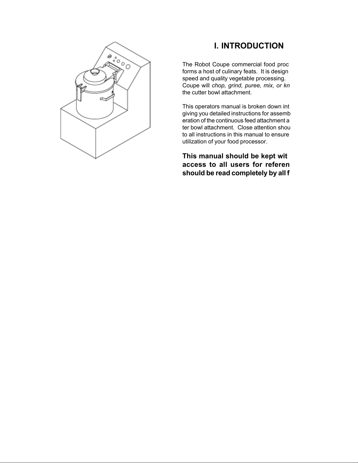
The Robot Coupe commercial food processor performs a host of culinary feats. It is designed for high
speed and quality vegetable processing. The Robot
Coupe will chop, grind, puree, mix, or knead using
the cutter bowl attachment.
This operators manual is broken down into sections
giving you detailed instructions for assembly and operation of the continuous feed attachment and the cutter bowl attachment. Close attention should be paid
to all instructions in this manual to ensure a long life
utilization of your food processor.
This manual should be kept within easy
access to all users for reference, and
should be read completely by all first time
users of the machine.
Maintaining the food processor in good working condition is one of the most important measures to be
taken. Inspect the machine and all parts regularly to
make sure they are in good working condition.
DO NOT operate a machine that has malfunctioned in any way.
Discard any food processed at the time
of a malfunction and have the machine inspected
and repaired at one of the Robot Coupe Authorized
Service Agencies, a list is provided in the back of this
manual. Contact one of these service agencies for
all of your service, parts and accessory requirements.
CAUTION: Your Robot Coupe comes
with a sharp cutting “S” blade. Always
handle with safety in mind. We suggest
that a pair of cut-resistant gloves be worn
when handling the “S” blade.
3
Page 4
R4Y and R6Y Series A
Operation Manual
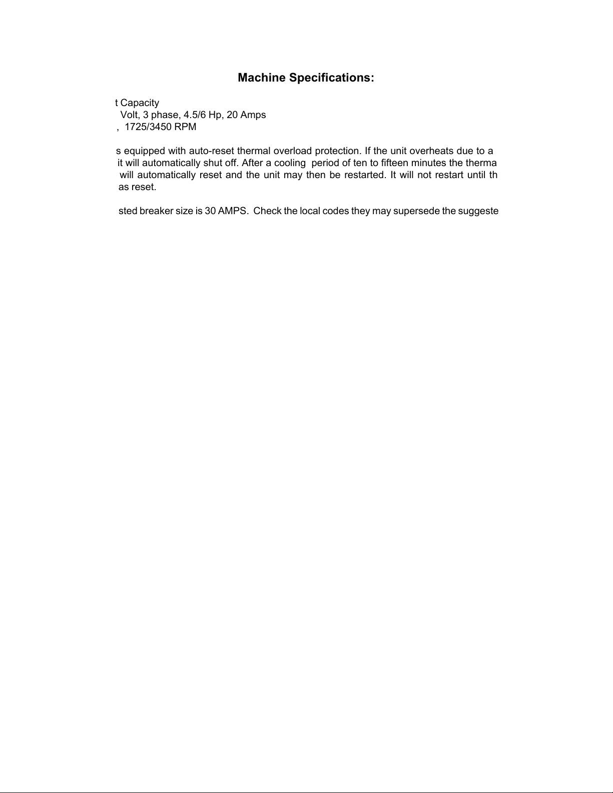
Machine Specifications:
R18 Quart Capacity
* 208-240 Volt, 3 phase, 4.5/6 Hp, 20 Amps
* 2 speed, 1725/3450 RPM
The R18 is equipped with auto-reset thermal overload protection. If the unit overheats due to an overload
condition, it will automatically shut off. After a cooling period of ten to fifteen minutes the thermal overload
protection will automatically reset and the unit may then be restarted. It will not restart until the thermal
overload has reset.
The suggested breaker size is 30 AMPS. Check the local codes they may supersede the suggested breaker
size.
4
Page 5

R4Y and R6Y Series A
Operation Manual
II. Operation
This manual is broken down into step by step
instructions to assist the operator in easy and quality
food preparation. This manual should be read
completely before use by each operator. Additionally,
this manual should be kept as a reference for future
operators. Adherence to the guidelines set forth by
this manual will ensure a safe, long life, utilization of
the vertical cutter mixer.
A. Blade Assembly
The R18 blade assembly comes assembled from the
factory. The blade assembly is designed so that the
blades can be adjusted for large or small batches.
The blade assembly should be completely
disassembled after each days use, washed
completely, and allowed to air dry before reassembly.
Additionally, the blades should be kept sharp to
provide the best performance. The blades can be
sharpened by means of a fine stone; a stone is
provided with each machine.
(5) Ensure that the blade assembly is correctly
assembled, and all parts fit tightly together before
beginning each operation.
(6) Sharpen the blades as necessary.
Blade Assembly:
NOTE: The placement of the blades is very important
to maintain the correct cutting performance and
balance. The blades should be located 120 degrees
apart when using the three blade system and 180
degrees apart when using the two blade system.
Locking Nut
The blades are set at the factory to allow for most
operations. The bottom blade should always stay on
the bottom, with the other blades evenly spaced.
There are two 5 mm. spacers and one 10 mm. spacer
available to adjust the blades. Most operations can
and should be run with the two small spacers between
the first and second blade and the medium spacer
between the second and third blades. Lower the top
blades only when small batches are to be run.
There are six important points to remember about the
blade assembly:
(1) The blades are sharp. Wear cut-resistant gloves
when handling the blade assembly.
(2) The bottom blade must always stay on the bottom
of the blade support.
(3) When placing the blade assembly on the motor
shaft for operation, ensure that the blade assembly
seats completely on the motor shaft. The blade
assembly should drop all the way to the bottom of the
bowl such that the bottom blade is almost touching
the bottom of the bowl.
(4) Disassemble the blade assembly at least after
each days use, wash completely, and allow to air dry
before reassembly.
Blade Support
Blade disassembly:
Included with the machine is a blade disassembly tool.
This consists of two pieces; the blade stop, and the
pry bar. The blade stop rests on the front bowl locking
bracket and prevents the blade assembly from rotating
during assembly and disassembly.
PLACE THE BLADE ON
1
PLACE THE BLADE STOP
ON THE FRONT BRACKET
3
ROTATE THE BLADE UNTILL IT RESTS AGAINST THE
BLADE STOP. CLOCKWISE TO TIGHTEN;
COUNTERCLOCKWISE TO LOOSEN.
2
THE MOTOR SHAFT.
4
INSERT PRY BAR. AND
TURN CLOCKWISE TO
TIGHTEN OR
COUNTERCLOCKWISE
TO LOOSEN
5
Page 6

R4Y and R6Y Series A
Operation Manual
Place the blade stop on the front bracket, and place
the blade assembly on the motor shaft. To
disassemble, rotate the blade counterclockwise until
one of the blades rests against the blade stop. Slide
the pry bar into the slot in the blade locking nut, and
turn it counterclockwise to loosen the nut. Unscrew
the blade locking nut for adjustments or cleaning, then
reverse this procedure when tightening the locking
nut.
When cleaning the blade assembly, it should be
completely disassembled. Allow all parts to dry before
reassembly. A light food-grade grease may be applied
to the threaded area to assist in easy removal. If the
blades are not disassembled on a regular basis, they
will become hard to disassemble.
B. Controls:
The Robot Coupe model R18 is designed with an easy
to use control panel. This machine offers a two speed
selector switch, push button run switch, push button
pulse switch, oversized mushroom type off switch,
and a power on and “ready to run” indicator lamps.
The following gives a brief description of each.
Red (power) Indicator Lamp:
This lamp will light when the machine is plugged in. If
the red lamp will not light then the machine should
be serviced.
Green (ready) Indicator Lamp:
This will light when the machine is ready to run.
The preceding description of the controls is
considered as normal operating conditions. If for any
reason they do not perform as indicated, the machine
should be serviced.
C. Operation:
Because of the special bowl and blade design of the
Robot Coupe Vertical Cutter Mixers, most operations
are completed in a matter of seconds. The operator
should pay close attention to the product as well as
the amount of time required to process. Most
operations should be run on Low speed, using High
speed only when an extremely fine puree consistency
is desired.
Two Speed Selector:
This switch allows the user to select either Low (1725
RPM) or High (3450 RPM) speed for the operation.
The middle position is a OFF position. For best
results, the speed selector should only be moved while
the machine is off and not running.
Run Switch:
This switch is used to start the machine. The machine
will not run unless the lid/safety switch is closed.
Pulse Switch:
This switch is used to jog or pulse the motor off and
on. The machine will not pulse on unless the lid/safety
switch is closed.
Stop Switch:
There are two ways to run your VCM. First of all, you
may run the unit continuously by filling the bowl with
food and simply letting it run until the desired
consistency has been reached. Use this method to
grind, mix, blend, puree, or emulsify. Secondly, you
may chop with your unit by pulsing the machine. Cut
round vegetables into halves or quarters and prep
long vegetables into 3 to 4 inch pieces. Place these
into the bowl, and using Low speed, pulse the unit on
and off quickly. Usually 4 to 5 pulses yields an evenly
mixed chopped substance.
TO CHOP
To achieve a chopped consistency for vegetables,
cheeses, meats, etc. fill the bowl with the product no
more than 3/4 full, or as low as two to three onions.
Small batches would require lowering the top cutting
blade. With the lid secured, and the speed selector
set to Low speed, press the pulse button quickly then
release. Repeat this pulsing action, allowing the
blades to stop each time, until the desired cut is
achieved.
The stop switch will stop the motor from running after
the run switch has been pressed.
6
Page 7

R4Y and R6Y Series A
Operation Manual
TO PUREE OR MIX
Fill the bowl with the product no more than 3/4 full.
Start the machine in Low speed and allow to run until
the product is completely reduced. If necessary, turn
the machine off, and select High speed to finish the
product. It may be necessary to add some liquids to
a puree to achieve the desired consistency.
DOUGHS AND PASTRIES
Prepare doughs and pastries on Low speed only. In
many cases it may be helpful to first mix all dry
products then add the liquids. The unit should be run
continuously until the product is completely
processed. For thick doughs, such as for pizza, the
machine will form a ball of dough when the mixing is
complete. When a ball is formed the machine should
be turned off immediately to prevent over processing.
Preparation times and all ingredients should be noted
for different recipes.
D. Emptying the Bowl
After the product has been run in the bowl, make
certain that the speed selector is in the off position,
and for extra safety unplug the machine. NEVER
attempt to open the lid until the blades have come to
a complete stop.
E. Cleaning
Cleaning is one of the most important measures to
ensure safe, quality, food preparation. The machine
should be cleaned after each session. Failure to keep
the machine clean can result in high repair costs and
shortened machine life. Follow the cleaning
instructions detailed below, or clean according to local
Health Department regulations.
Remove the lid:
The lid is removed by pulling out the lid hinge pin
located at the base of the lid.
Remove the blades:
The blades can be lifted out
Remove the bowl:
Remove the bowl by loosening the locking nut on front
of the bowl and twisting the bowl clockwise.
The bowl, blades, and lid can be cleaned in a pot sink
or dishwasher. Be careful not to bend, drop, or break
any of the components.
using a non-metal-safe detergent. High alkaline
detergents can cause damage to the aluminum lid.
The blade assembly should be disassembled
according to previous instructions. Thoroughly clean
the parts and allow the parts to dry completely before
reassembly.
Note: DO NOT clean the lid
To remove the bowl, loosen the knob on the front of
the bowl and twist the bowl clockwise, thus releasing
the locking lugs. Then lift the entire bowl, with the
blade assembly intact, up and off of the motor shaft.
The bowl can then be emptied by holding the blade in
place and tilting the bowl to one side into a catch pan
or other container. In the case of liquids, try placing
the bowl on top of a container and removing the blade
assembly, thus allowing the liquid to drain through
the bottom hole.
CAUTION: Wear cut-resistant gloves
when handling the blade assembly
With the bowl removed, the motor shaft and seal
should be cleaned. Use a soft brush or cloth to clean
the seal area. The seal is designed to prevent
penetration of liquids and food products into the motor
housing. Clean the seal area completely, yet do not
damage the seal. Inspect the seal during each
cleaning for damage or wear. A tool is provided with
the machine for removing the seal. The seal should
be replaced if any wear or damage is noted. Contact
an authorized service agent for additional seals.
NOTICE: It is recommended that the seal be
lubricated at least once a week or after cleaning as
practical. A food-grade grease, vegetable oil, or
mineral oil will work well.
Clean the motor base/housing using a cloth
dampened with a soapy water solution. Clean the
entire motor base, pay special attention to the seal
area and lid mounting plate. Maintaining a clean
machine will improve the overall life of the unit.
7
Page 8

R4Y and R6Y Series A
Operation Manual
DO NOT spray the motor base with
running water. Although the unit is
protected from casual water and spills, it
is not designed to be cleaned using
forced liquids. Do not immerse the motor
base in any liquid.
III. PREVENTATIVE
MAINTENANCE
A. Inspection:
The Robot Coupe Vertical Cutter Mixers are designed
to give years of maximum trouble free performance.
Adherence to the operating instructions as well as
keeping the unit clean will further assure good
performance.
An examination should be made periodically to assure
that all parts are in good working condition. Special
attention should be given to all seals to insure that
they are well lubricated and clean. Replacement of
the seals may be necessary if they are dry rotted or
torn.
The seal around the motor shaft must be maintained
in good condition. The seal should be kept clean and
lubricated at all times. A clean and well maintained
seal will last a long time, and under these normal
working conditions the seal should be replaced every
six to eight months as a preventative maintenance
measure to ensure that a good seal is being
maintained. However, if the seal area is not kept
clean, you may need to replace the seal every three
to four months. One spare seal assembly is included
with each machine. This seal assembly should be
kept on hand in a safe place for future use. The seal
assembly are also available through our authorized
service network, part number R1027.
Also included is a spare set of O-Rings for the lid.
This includes a large and a small O-Ring to be used
as a replacement for worn or damaged O-Rings.
8
Page 9

R4Y and R6Y Series A
Operation Manual
B. R18 Motor Seal Assembly Replacement:
NOTE: ONLY QUALIFIED SERVICE OR REPAIR
TECHNICIANS SHOULD PREFORM THIS SER-
VICE.
The machine comes equipped with a removable seal
assembly that is screwed down around the motor
shaft. To replace the seals, this assembly must be
unscrewed. A tool is supplied for use in removing the
insert.
Follow steps 1-6 below to replace the motor seals.
NOTE: Damage caused to the motor by
failure to maintain the motor support seal
in good working condition is not covered
under warranty.
Inspect the machine on a regular basis. If the machine
becomes damaged in any way, or fails to operate as
indicated in this manual, remove the machine
immediately from use and have it serviced by an
authorized agent. Discard any food processed at the
time of a malfunction.
IV. SERVICE:
If service is required, contact the nearest authorized
service agency, or your distributor, to see where
service is available. If you have difficulty finding
service information call the factory at the number listed
below.
Robot Coupe, USA Inc.
1-800-824-1646
1. Remove the seal assembly:
Place the tool over the shaft and around the
seal assembly.
Turn the tool counterclockwise to loosen.
Place a heavy-duty screwdriver through the
holes in the tool for more leverage.
4. Clean the shaft, then tape the step on
the shaft with plastic electrical tape for protection during reassembly.
Using a food-grade grease, lightly lubricate
the shaft.
2. Pry out the seals and
clean the seal cavity.
5. Install new seals with
grooved greased sides facing each other.
The seals must be fully seated. Gentely
tap them into place with a hammer and
small block of wood if necessary, but do
not damage them.
3. Grease the seals
6. Reinstall the seal assembly:
Before reassembly, lightly grease the threads on the seal
assembly insert. Place the seal assembly over the motorshaft and screw it down gently turning first by hand, then with
the tool in a clockwise rotation until it is firmly in place.
Remove the plastic tape and excess grease before using the
machine.
9
Page 10

Page 11

b
b
b
b
R18
Part # Description
CL689
Number not availa
Number not availa
Number not availa
Number not availa
R1004
R1006
R1008A
R1009
R1012
R1015
R1016
R1017
R1018
R1019A
R1019B
R1020
R1022
R1024
R10252
R1027
R1029
R1030
R1032
R1032A
R1034
R1036A
R1037A
R1037E
R1038
R1039
R1039A
R1040
R1040A
R1041
R1043A
R1044
R1045
R1049
R1051
Tool,Seal Removal
Description Not available
Description Not available
Description Not available
Description Not available
Top Seal, Motor
Bracket, Foot
Strain Relief (ETL&P)
Switch Knob,Speed Selec.
Eclip
Switch, Stop (Red)
Light, Green
Light, Red
Pin, Lid Hinge
Bracket/Lid Mount(Round)
Bracket, Lid Mount
Stop, Lid
String, Lid Hinge Pin Se
Screw, Motor Support
Magnetic Switch Assy
Seal Assy, Motor Support
Shield, Motor Support
Knob, Bowl Securing
Seal, Lid
Seal, Lid
Cover,Screw (MS 21MM)
Screw, Lid Lever
* Lid Assembly
*Lid Assembly (Pin w/Seal)
O Ring, Lid
Bolt, Lid Spring
Bolt, Lid Spring
Spring, Lid
Spring, Lid
Screw, Bolt Locking
Screw W/ Nut, Lid Sen. (Mech Sw.)
O Ring, Trans Lid Cover
Transparent Cvr, AssyLid
Bowl Magnet Assy.
Proximity Switch (24V)
* Denotes Accessories
7/21/03
Page 12

R1053
R1054
R1057
R1058
R1061
R1062
R1065A
R1065C
R1071
R1072
R1072A
R1075
R1076A
R1077
R1078
R1080
R1082
R1083
R1084
R1091A
R114
R1503
R1540
R1547A
R1549
R1577
R1801
R1802
R1803
R1807
R1809
R1810
R1821
R1822
R1823
R1826
R1854
R1863
R1870
R1871
R1875
R1880
R1882
R25142
R25162
R2534A
R3063U
R3067U
R611
R8U009
Fuse Holder
Fuse Block w/Fuse & Hold
Gromet, Elec Cord
Bolts, Shock Absorb.
P/C Board
Bolts, Shock Absorbing
Bushing 25M (Prox Sw)
Bushing
Blade Support
Blade Only, St.
Blade Only, Ser.
Tool, Blade Locking
50MM S. Spacer
Plastic Spacer (10 cm)
Lock Nut, Blade
2 Speed Drum Switch
Seal (27x36x6.5)
Seal (JF410A)
Handle
Lever Latch Assy
Switch Only
Foot
Bearing (6206)
Bushing (New Style)
Wheel Assy.
30amp Plug (R15 R25T)
Base
Front Name Plate
Wheel
Motor (RCSA)
Gasket, Access Cover
Cover, Back Access
Motor Support
Screw, Motor Support
Screw Cover
* Bowl
Data Plate
Spacer 30MM
* Blade Assy Comp(Straight
* Blade Assy Comp(Serrated
Transformer
Fuse 20A 400V
Terminal Block (Canada Only)
Cord (R25T R40T)
Bottom Bearing (R25T,TP)
Mechanical Switch Assy.
Pulse Push Buttn,Black
On Push Button/Green
Motor Support Seal
15 mm S.S. Spacer
* Denotes Accessories
7/21/03
Page 13

U.S.A., Inc.U.S.A., Inc.
U.S.A., Inc.
U.S.A., Inc.U.S.A., Inc.
PP
.O. Box 16625, Jackson, MS 39236-6625.O. Box 16625, Jackson, MS 39236-6625
P
.O. Box 16625, Jackson, MS 39236-6625
PP
.O. Box 16625, Jackson, MS 39236-6625.O. Box 16625, Jackson, MS 39236-6625
280 South Perkins St., Ridgeland, MS 39157280 South Perkins St., Ridgeland, MS 39157
280 South Perkins St., Ridgeland, MS 39157
280 South Perkins St., Ridgeland, MS 39157280 South Perkins St., Ridgeland, MS 39157
email: robocoup@misnet.comemail: robocoup@misnet.com
email: robocoup@misnet.com
email: robocoup@misnet.comemail: robocoup@misnet.com
website: www.rwebsite: www.r
website: www.r
website: www.rwebsite: www.r
1-800-824-16461-800-824-1646
1-800-824-1646
1-800-824-16461-800-824-1646
obotcoupeusa.comobotcoupeusa.com
obotcoupeusa.com
obotcoupeusa.comobotcoupeusa.com
ROBOT COUPE U.S.A., INC. LIMITED WARRANTY
YOUR NEW ROBOT COUPE PRODUCT IS WARRANTED TO THE ORIGINAL PURCHASER
FOR A PERIOD OF ONE YEAR FROM THE DATE OF PURCHASE.
This LIMITED WARRANTY is against defects in the material and/or workmanship, and includes labor for
replacement of defective parts, provided repairs are performed by an authorized service agency (see attached
list). The
copy of the dated sales or delivery receipt BEFORE WARRANTY REPAIRS ARE BEGUN. Replacement parts
and accessories are warranted for ninety (90) days from the date of purchase when purchased separately and
will be verified by dated sales receipt OR packing slip which lists that item. All parts or accessories replaced
under warranty must be returned to the Service Agency.
CUSTOMER must inform the Service Agency of the possibility of warranty coverage and provide a
THE FOLLOWING ARE
1. Damage caused by abuse, misuse, dropping, or other similar incidental damage caused by or as
a result of failure to follow assembly, operating, cleaning, user maintenance, or storage
instructions.
2. Labor to sharpen and/or parts to replace knife assemblies or blades which have become dull,
chipped, or worn due to normal use.
3. Material or labor to renew or repair scratched, stained, chipped, dented or discolored surfaces,
blades, knives, attachments, or accessories.
4. Transportation charges to or from an authorized service agency for repairs of a machine designated
as “CARRY IN SERVICE” (table top models). NOTE: R4N/R6N are now field service units.
5. Labor charges to install or test attachments or accessories (i.e., bowls, cutting plates, blades,
attachments) which are replaced for any reason.
6. Charges to change Direction-of-Rotation of Three Phase electric motors (INSTALLER IS
RESPONSIBLE).
7. SHIPPING DAMAGE IS NOT COVERED BY WARRANTY. Visible and hidden damages are the
responsibility of the freight carrier. The consignee must file a damage claim promptly against the
carrier, or upon discovery in the case of hidden damage.
KEEP ALL ORIGINAL CONTAINERS AND PACKING MATERIALS FOR CARRIER INSPECTION.
“NOT” COVERED UNDER WARRANTY:
Robot Coupe U.S.A., Inc., Robot Coupe S.A. or any of their affiliates, distributors, officers, directors, agents,
employees, or insurers will not be obligated for consequential or other damages, losses, or expenses in connection
with or by reason of the use of or inability to use the machine for any purpose.
THIS WARRANTY IS GIVEN EXPRESSLY AND IN LIEU OF ALL OTHER WARRANTIES, EXPRESSED
OR IMPLIED, FOR MERCHANTABILITY AND FOR FITNESS TOWARD A PARTICULAR PURPOSE
AND CONSTITUTES THE ONLY WARRANTY MADE BY ROBOT COUPE, U.S.A., Inc.
 Loading...