

Page 1

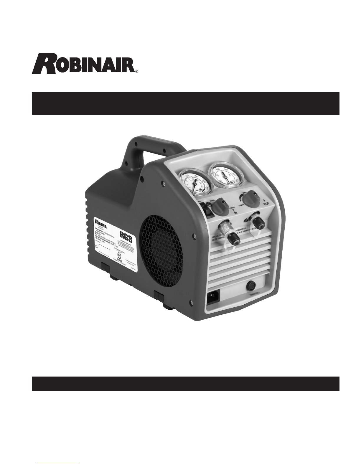
Refrigerant Recovery Machine
Model No. RG3
Operating Manual
Manual de operaciones
Manuel d’utilisation
1
Page 2

Safety PrecautionS
WARNING : TO PREVENT PERSONAL INJURY AND / OR EQUIPMENT DAMAGE,
ALLOW ONLY QUALIFIED PERSONNEL TO OPERATE THIS UNIT. Before operating the unit,
read and follow the instructions and warnings in this manual. The operator must be familiar with air
conditioning and refrigeration systems, refrigerants, and the dangers of pressurized components. If
the operator cannot read this manual, operating instructions and safety precautions must be read and
discussed in the operator’s native language.
PRESSURIZED TANK CONTAINS LIQUID REFRIGERANT. Do not overll storage vessels, because
overfilling may cause explosion and personal injury or death. Do not recover refrigerants into
nonrellable containers; use only federally authorized rellable containers (DOT spec. 4BW or 4BA).
HOSES MAY CONTAIN LIQUID REFRIGERANT UNDER PRESSURE. Contact with refrigerant may
cause personal injury. Wear protective equipment, including safety goggles and protective gloves.
Disconnect hoses using extreme caution.
AVOID BREATHING A/C REFRIGERANT AND LUBRICANT VAPOR OR MIST. Exposure may
irritate eyes, nose, and throat. To remove refrigerant from the A/C systen, use only equipment certied
for the type of refrigerant being removed. Use the unit in locations with mechanical ventilation that
provides at least four air changes per hour. If accidental system discharge occurs, ventilate the work
area before resuming service.
TO REDUCE THE RISK OF FIRE, USE THE SHORTEST POSSIBLE EXTENSION CORD WITH A
MINIMUM SIZE OF 14 AWG. Using an undersized extension cord may result in electrical equipment
failure.
TO REDUCE THE RISK OF FIRE, do not use the unit in the vicinity of spilled or open containers of
gasoline or other ammable substances.
CAUTION – DO NOT PRESSURE TEST OR LEAK TEST EQUIPMENT OR VEHICLE AIR
CONDITIONING SYSTEMS WITH COMPRESSED AIR. Some mixtures of air and refrigerant have
been shown to be combustible at elevated pressures. These mixtures, if ignited, may cause injury or
property damage.
DO NOT MIX REFRIGERANT TYPES THROUGH A SYSTEM OR IN THE SAME CONTAINER.
Mixing of refrigerants causes severe damage to the unit and the system being serviced.
HIGH VOLTAGE ELECTRICITY INSIDE THE UNIT HAS A RISK OF ELECTRICAL SHOCK. Exposure
may cause personal injury. Disconnect power before servicing the unit.
Additional health and safety information may be obtained from
refrigerant and lubricant manufacturers.
Explanation of SafEty Signal WordS
WARNING : Indicates a potentially hazardous situation which, if not avoided, could result in death or
serious injury.
CAUTION : Indicates a potentially hazardous situation which, if not avoided, may result in minor or
moderate injury.
CAUTION : Used without the safety alert symbol indicates a potentially hazardous situation which, if not
avoided, may result in property damage.
2
Page 3

table of contentS
Safety Precautions . . . . . . . . . . . . . . . . . . . . . . . . . . . . . . . . . .2
Explanation of Safety Signal Words . . . . . . . . . . . . . . . . . . . . . . . . .2
Understanding Refrigerant Recovery . . . . . . . . . . . . . . . . . . . . . . . . 4
Standard Operating Instructions . . . . . . . . . . . . . . . . . . . . . . . . . . .5
Setup . . . . . . . . . . . . . . . . . . . . . . . . . . . . . . . . . . . . . 5
Recovery Procedure . . . . . . . . . . . . . . . . . . . . . . . . . . . . .6
Operating Instructions for Bulk Liquid Systems . . . . . . . . . . . . . . . . . . . 7
Push – Pull Procedure . . . . . . . . . . . . . . . . . . . . . . . . . . . . 7
Liquid Recovery. . . . . . . . . . . . . . . . . . . . . . . . . . . . . . . .7
Vapor Recovery . . . . . . . . . . . . . . . . . . . . . . . . . . . . . . . .8
Purge Non-Condensable Gas from a Storage Cylinder . . . . . . . . . . . . . . .8
Recovery Cylinder Information
Troubleshooting . . . . . . . . . . . . . . . . . . . . . . . . . . . . . . . . . . 10
Replacement Parts, Rebuild Kits, & Accessories
Maintenance . . . . . . . . . . . . . . . . . . . . . . . . . . . . . . . . . . . . 12
Installation of the Filter and Filter / Drier . . . . . . . . . . . . . . . . . . 12
Burned-out System . . . . . . . . . . . . . . . . . . . . . . . . . . . . . 12
Storage . . . . . . . . . . . . . . . . . . . . . . . . . . . . . . . . . . . 12
Spanish
French
Warranty Statement
. . . . . . . . . . . . . . . . . . . . . . . .Inside Back Cover
. . . . . . . . . . . . . . . . . . . . . . . . . . . .9
. . . . . . . . . . . . . . . . . 11
3
Page 4

underStanding refrigerant recovery
NOTE: Throughout this operating manual the term “unit”
is used when referring to the RG3 refrigerant recovery
machine.
Refrigerant recovery is the process of taking refrigerant
out of a system and storing it in a cylinder. The following
information is critical to achieving the best refrigerant
recovery results.
Refrigerant
Identify the refrigerant type and quantity in the system to
be serviced.
The unit is approved for use with the following category
III, IV, and V refrigerants (per ARI-740) :
R-12, R-22, R-134a, R-401a, R-401b,R-401c, R-402a,
R-402b, R-404a, R-406a, R-407a, R-407b, R-407c,
R-407d, R-408a, R-409a, R-410a, R-411a, R-411b,
R-412a, R-500, R-502, R-507 R-509
Filters and Filter / Driers
CAUTION : Filters prevent contamination from
entering the unit, which reduces the risk of damage
to the unit and the system being serviced.
The unit is shipped with a lter screen installed behind
the inlet tting. Robinair strongly recommends that a
clean lter screen be used for every service job. Failure
to use a lter screen will invalidate your warranty.
The unit is also shipped with (1) lter / drier (Part No.
100343) for use at the inlet tting. However, if there is a
need to recover multiple, different refrigerants using this
unit, a separate lter / drier must be labeled and used for
each individual type of refrigerant.
Valves
WARNING : To prevent personal injury, open
service and cylinder valves SLOWLY to allow
rapid shut-off of gas flow if necessary. Once it is
determined there is no danger, the valves may be
opened fully.
Isolate large amounts of refrigerant and close valves
after use, so if a leak should develop anywhere in the
system, refrigerant will not escape to the atmosphere.
Hoses
Hoses must be equipped with low-loss ttings and have
pressure ratings appropriate for the refrigerant in the
system being serviced.
Shut-off Switch
This unit has an internal, high-pressure, shut-off switch.
If system pressure rises above 550 psi, the unit shuts
off. The shut-off switch automatically resets itself after
pressure drops below 400 psi.
WARNING : The internal pressure shut-off
switch does NOT prevent cylinder overfill. If the
system shuts off automatically and is connected
to a cylinder, the cylinder may be dangerously
overfilled. Take immediate measures to relieve the
high pressure and / or cylinder overfill situation, or
personal injury may result.
Push / Pull Procedure
When recovering large amounts of liquid (over 15 lbs.),
use the Push / Pull method described in this manual.
Maximum Vacuum and Recovery Rates
To achieve the deepest nal vacuum, use an evacuated
recovery cylinder. To maximize recovery rates :
Use the shortest possible length of 3/8 in. or larger
•
hose. (A hose no longer than 3 feet is recommended.)
Remove unnecessary hose core depressors, and
•
remove Schrader valves from port connections.
Deformed rubber seals and core depressors in hoses,
as well as faulty or unnecessary Schrader valves, can
restrict ow.
Maintenance
CAUTION : Keep all connections to the refrigeration
system dry and clean. Damage will occur if moisture
is allowed to enter the system.
Storage Cylinders
WARNING : A storage cylinder is full when it
reaches 80% volume. DO NOT OVERFILL. Due to
liquid expansion, the cylinder could explode if filled
to more than 80% volume, possibly causing personal
injury and equipment damage. Use a scale, such as
TIF9010A, to avoid overfilling the storage cylinder.
4
Page 5

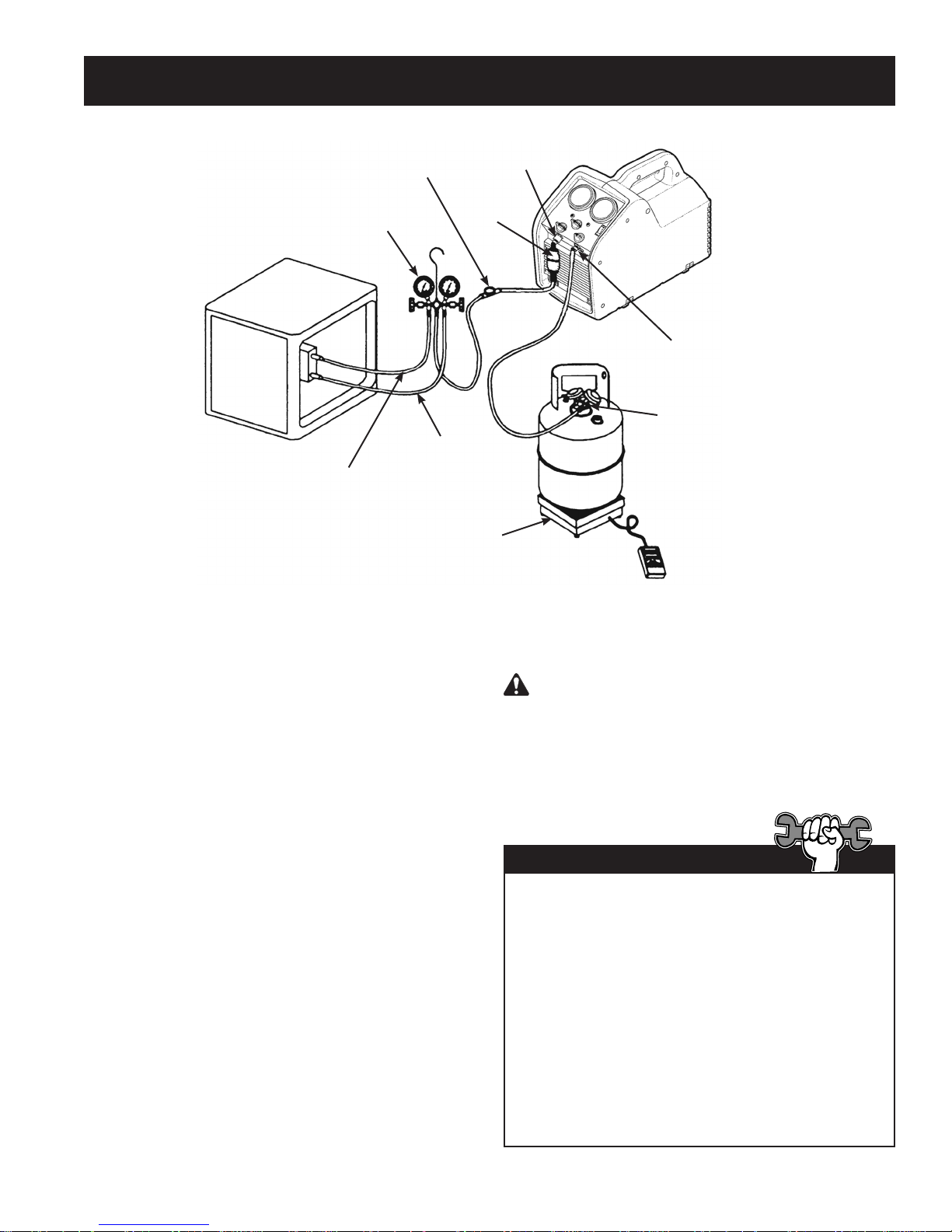
Standard oPerating inStructionS
Manifold
Gauge Set
System Being
Serviced
Vapor
Sight
Glass
Filter / Drier
Liquid
Scale
Inlet
Fitting
Outlet
Fitting
Liquid Port
Recovery
Cylinder
The following instructions are for a standard or
“common” recovery procedure.
Setup Procedure
1. Place the unit on a at, level surface.
2. Verify a clean lter screen is installed behind
the inlet tting.
3. Connect a hose from the outlet tting of the
unit to the liquid port on the recovery cylinder.
4. Connect a hose from the inlet tting of the unit
to the output port of a manifold gauge set.
Robinair recommends using a sight glass and
a lter / drier in this line.
5. Connect a hose from the liquid (low pressure)
side of the manifold gauge set to the liquid side
of the system being serviced.
6. Connect a hose from the vapor (high) side of
the manifold gauge set to the vapor side of the
system being serviced.
7. Verify the inlet and outlet valves on the unit are
closed.
8. Place the recovery cylinder on a scale (such as
TIF9010A) to avoid overlling the cylinder.
WARNING : A storage cylinder is full when
it reaches 80% volume. DO NOT OVERFILL. Due
to liquid expansion, the cylinder could explode
if lled to more than 80% volume, possibly
causing personal injury and equipment damage.
Tech Tips
The unit will perform at its peak when voltage
entering the machine (while operating) is between
115 —122 VAC.
Lower supply voltages may result in difculty
starting under high head pressure, reduced
performance, and / or motor overheating.
Use an outlet that does not have other applicances
(such as lights, machines, etc.) plugged into it.
Do not use an extension cord unless needed. If
an extension cord is used, it must be 14 AWG
minimum and as short as possible to reduce
voltage drops.
5
Page 6

Standard oPerating inStructionS
Recovery Procedure
1. Connect the unit to an appropriate 115 V outlet.
2. Slowly open the liquid valve of the recovery
cylinder while watching hoses and connections
for leaks.
3. Open the liquid valve on the manifold gauge set.
Note: Opening the liquid valve removes liquid from
the system rst, greatly reducing recovery time.
4. Open the outlet valve on the unit.
5. Toggle the power switch to the ON position.
6. Slowly open the inlet valve on the unit. Note: If the unit begins to “knock”, slowly throttle back (close)
the inlet valve until the noise stops.
7. Once the liquid has been removed from the system, open the vapor valve on the manifold gauge set to
nish evacuating the system.
8. Run the unit until the desired vacuum is achieved.
9. Close the vapor and liquid valves on the manifold gauge set.
10. Turn the inlet valve on the unit to the CLOSED position.
11. Toggle the power switch OFF.
6
Page 7

oPerating inStructionS for bulk liquid SyStemS
“Push – Pull” Procedure
The push – pull method removes bulk liquid from a system using the pressure differential created by the
unit. This method works only with large systems where the liquid is readily accessible; it may not work on
systems that contain less than 15 lbs. (6.8 kg) bulk liquid.
This method is used :
• on systems with receiver cylinders.
• on systems containing more than 20 lbs.
(9.1 kg) of refrigerant.
• when transferring bulk liquid refrigerant
from one cylinder to another.
System Being
Serviced
Inlet
Fitting
Filter/Drier
Outlet Fitting
Vapor
WARNING : Manually close the valves on both
the storage cylinder and the unit to prevent overfilling
the cylinder. Once the siphon is started, it can overfill
the storage cylinder, even if the cylinder is equipped
with a float level sensor. The siphon can continue
even when the unit is turned off.
Liquid
Liquid Recovery
1. Place the unit on a at, level surface.
2. Connect a hose from the outlet tting of the unit
to the vapor port on the system being serviced.
3. Connect a hose from the inlet tting of the
unit to the vapor port of a recovery cylinder.
Robinair recommends using a lter / drier in
this line.
4. Connect a hose from the liquid side of the
recovery cylinder to the liquid port of the
system being serviced. Robinair recommends
using a sight glass in this line as a method of
determining when the liquid has been removed.
5. Place the recovery cylinder on a scale (such as
TIF9010A) to avoid overlling the cylinder.
Vapor
Recovery
Cylinder
Sight
Glass
Scale
Liquid
6. Verify inlet and outlet valves on unit are closed.
7. Open the recovery cylinder valves.
8. Open the outlet valve on the unit.
9. Toggle the power switch ON.
10. SLOWLY open the inlet valve on the unit.
11. When the weight reading on the scale stops
increasing, close the inlet valve on the unit
rst; then close the liquid valve on the recovery
cylinder.
12. Toggle the power switch OFF.
13. Close the valves on the recovery cylinder, and
close the outlet valve on the unit.
14. Proceed to Vapor Recovery.
7
Page 8

Operating instructiOns fOr Bulk liquid systems
Vapor Recovery
1. Place the unit on a at, level surface.
2. Connect a hose from the inlet side of the unit to
the liquid port of the system being serviced.
Tech Tip
3. Connect a hose from the outlet side of the unit
to the liquid port on a recovery cylinder.
CAUTION: The recovery cylinder should be
on a scale to avoid overlling the cylinder.
4. Open the liquid valve on the recovery cylinder.
5. Open the outlet valve on the unit.
6. Toggle the power switch ON.
7. Slowly open the inlet valve on the unit.
8. Run the unit until the desired vacuum is
achieved.
9. Close the inlet and outlet valves on the unit.
10. Toggle the power switch OFF.
11. Close the ports on the recovery cylinder.
For a faster recovery procedure, recover from both
the liquid and vapor ports of the system being
serviced by using a tee tting or manifold gauge
set in the hose setup.
purge nOn-cOndensaBle gas frOm a stOrage cylinder
1. Allow the storage cylinder to sit undisturbed for
24 hours to allow air to rise to the top.
2. Connect a manifold gauge set to the cylinder.
Read the amount of pressure in the cylinder as
indicated by the output pressure gauge.
3. Determine the ambient temperature in the
room.
4. Refer to a refrigerant pressure / temperature
chart and nd the ambient temperature. Read
across the chart to the corresponding pressure
for the type of refrigerant in the cylinder.
Determine how that relates to the reading on
the gauge.
5. If the pressure reading in the cylinder is
higher than the pressure shown on the chart,
VERY SLOWLY crack open the vapor port
valve. (This is done slowly to cause as little
turbulence inside the cylinder as possible.)
Watch the pressure on the gauge decrease. To
prevent venting, add 4–5 psi (0.26—0.34 bar)
to the pressure shown on the chart.When the
gauge corresponds to that pressure, close the
vapor port valve.
6. Allow the cylinder to sit for 10 minutes and then
check pressure again.
7. Repeat the process, if necessary.
8
Page 9

recovery cylinder information
Type of Cylinder
Use only authorized, rellable, refrigerant storage
cylinders. Federal regulations require refrigerant
to be transported only in containers meeting DOT
specs. 4BW or 4BA.
NEVER use a standard disposable 30 lb.
(13.6 kg) cylinder (the type of container in which
new refrigerant is sold) to recover refrigerant.
Working Pressure
Recovery cylinders are designed for different
working pressures. Robinair strongly recommends
the use of 400 psi (27.6 bar) cylinders.
WARNING: To prevent personal injury, do
not exceed the rated working pressure of the
cylinder. At minimum, the RG3 requires the use
of a 350 psi (24.1 bar) recovery cylinder.
NOTE: The use of a 400 psi (27.6 bar) cylinder is
mandatory when recovering R-410A refrigerant.
Refer to the Parts and Accessories section of this
manual for more information.
If you expect temperatures in excess of 135º F
(57° C), consult the refrigerant supplier.
Capacity
Safety codes state that closed cylinders should
not be lled with liquid over 80% of volume. (The
remaining 20% is called head pressure room.)
Do not exceed 80% of cylinder capacity. Robinair
recommends the use of the TIF9010A Refrigerant
Scale for monitoring cylinder capacity.
Refrigerants
Cylinders and lter / driers should each be
designated for only one type of refrigerant.
If you must use a cylinder previously used for
a different refrigerant, prepare the cylinder by
completely emptying it, perform an evacuation,
purge it using dry nitrogen, and then perform
another evacuation.
Storage
Store refrigerant cylinders in a cool, dry place.
Leakage
Some cylinders have valves that were not correctly
seated when manufactured. Keeping caps on the
valves will guard against refrigerant leakage.
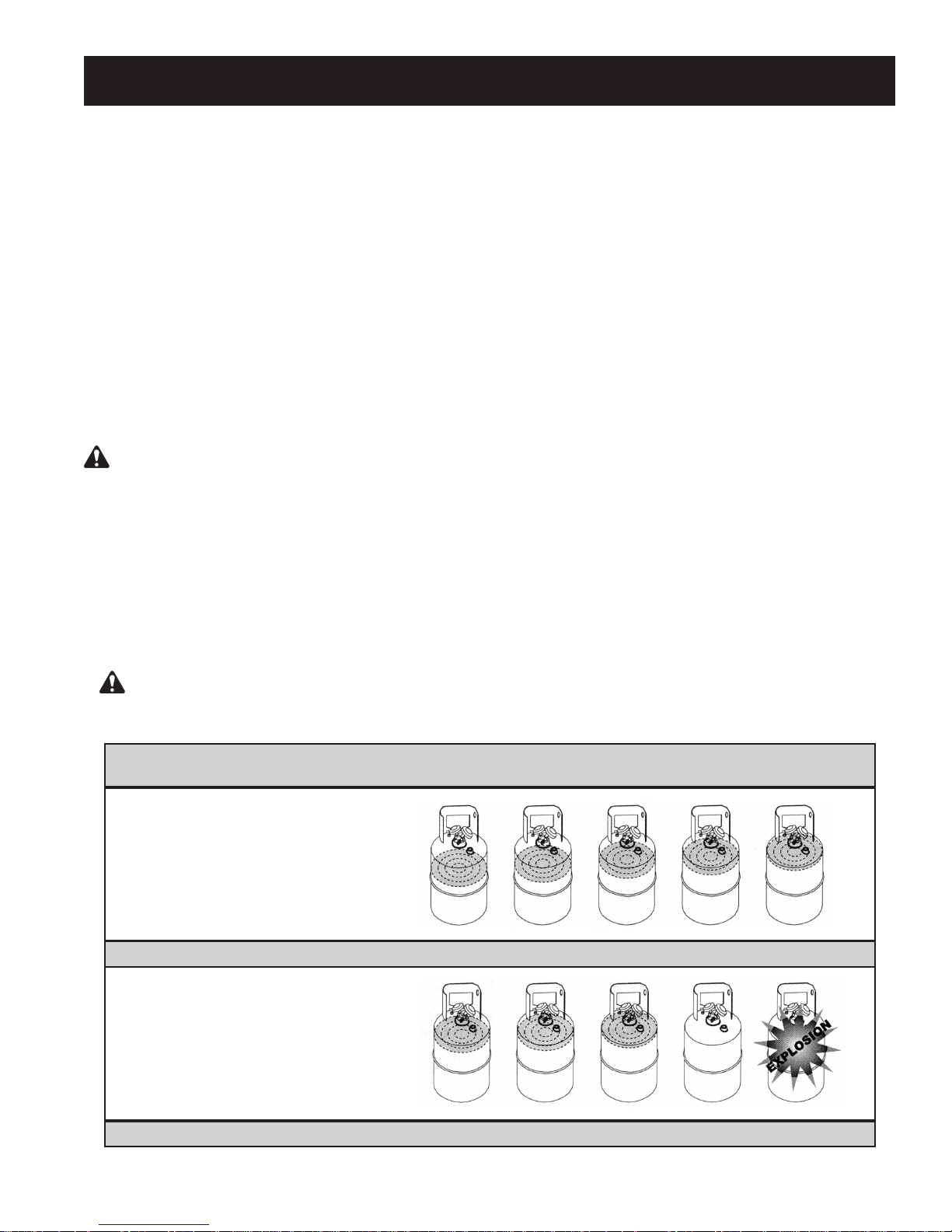
WARNING : To prevent personal injury, never transport an overfilled cylinder.
Refrigerant expands when it gets warm and may cause an overfilled cylinder to explode.
Storage Cylinder Temperature 60°F 70°F 100°F 130°F 150°F
15.6°C 21.1°C 37.8°C 54.4°C 65.6°C
STARTING WITH CYLINDER
80% BY VOLUME
Space Occupied by Liquid 80% 81% 83% 90% 94%
STARTING WITH CYLINDER
90% BY VOLUME
Space Occupied by Liquid 90% 92% 96% 100%
9
Page 10

troubleShooting
WARNING: TO PREVENT PERSONAL INJURY AND / OR EQUIPMENT DAMAGE,
ALLOW ONLY QUALIFIED PERSONNEL TO OPERATE AND REPAIR THIS UNIT. Before operating
or repairing the unit, read and follow instructions and warnings in this manual. The technician
must be familiar with air conditioning and refrigeration systems, refrigerants, and the dangers
of pressurized components. If the technician cannot read this manual, operating instructions
and safety precautions must be read and discussed in the technician’s native language.
Symptom Possible Cause Possible Solution
Unit will not turn on 1. Power cord not plugged in.
2. Bad power outlet.
3. Unit is in high-pressure shut-off.
4. Motor is in thermal overload.
5. Blown or bad fuse.
Compressor tries to
start, but just buzzes
Unit pumps into
high-pressure shut-off
Slow recovery 1. Trapped liquid in system.
1. Low voltage at power source.
2. Extension cord too long, or too
small.
1. Output valve on unit is closed.
2. Recovery cylinder valve closed.
3. Head pressure too high.
2. Restriction in refrigerant ow path.
1. Check power cord at wall and unit.
2. Try a different outlet.
3. Reduce head pressure to below
400 psi (27.6 bar).
4. Allow motor / unit to cool down.
5. Check / replace fuse.
1. Locate / use better outlet.
2. Reduce length of extension cord.
Increase size (gauge) of extension
cord (14 AWG minimum).
1. Check output valve.
2. Check recovery cylinder valve.
3. Check output hoses for restrictions
or kinks. Reduce head pressure.
1. Momentarily cycle system compressor
to move trapped refrigerant.
2. Check inlet hose for restrictions or
kinks. Remove Schrader valves and
core depressers from hoses (if
possible). Use larger hoses.
Blown fuse 1. Electrical short in wiring.
2. Mechanical binding.
1. Check for and replace damaged
wires and / or electrical connectors.
2. Repair or replace compressor.
10
Page 11

rePlacement PartS
12
13
20
1
15
16
4
3
17
5
2
7
8
}
18
10
6
9
14
21
Item Part
No. No. Qty. Description
1 570895 1 Case Kit (both halves)
2 SK-3001 1 Interface Kit (motor-compressor
interface, coupler, hardware)
3 SK-3003 1 Fan
4 SK-3004 1 Motor Kit
(motor, capacitor, hardware)
5 565504 1 Compressor
6 SK-3006 1 Condenser
7 565502 1 Gauge Lens (1 ea.)
8 565617 1 Motor Start Capacitor
9 SK-3007 1 Low-side Gauge Kit
(low-side gauge, lens)
10 SK-3008 1 High-side Gauge Kit
(high-side gauge, lens)
11 SK-3005 1 High-side Manifold Kit
12 565501 1 Front Bezel
13 SK-6001 1 Inlet Fitting / Filter Screen Kit
(inlet tting, lter screen, o-ring)
11
19
Item Part
No. No. Qty. Description
14 565500 1 Fuse
15 550503 1 Grommet (1 ea.)
16 SK-3009 1 Motor Clamp Kit (4 pieces)
17 550502 1 Foot (1 ea.)
18 565616 1 Inlet Tube
19 551628 1 Power Cord
20 EL1310 1 Power Switch
21 SK-3010 1 Low-side Manifold Kit
100343 1 Filter / Drier (not shown)
100345 6 in. Blue Hose (not shown)
Rebuild Kits
SK-3011 Compressor Rebuild Kit (piston
seals, valves, springs, o-rings)
SK-6007 Valve Rebuild / Replacement Kit
(inlet / outlet valves, springs, o-rings)
11
Page 12

maintenance
CAUTION : To prevent personal injury, disconnect the unit from the power supply before
performing maintenance.
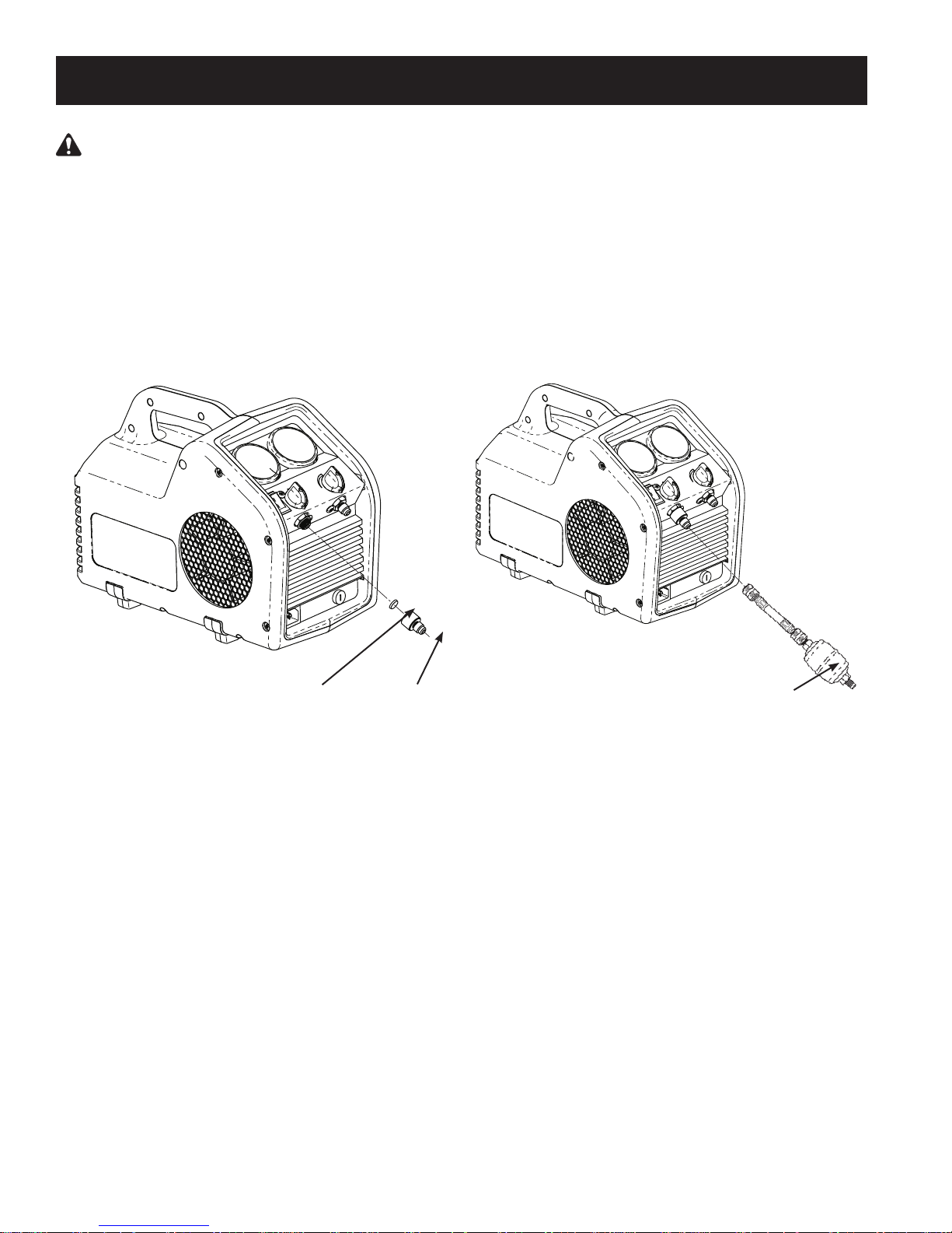
Installation of the Filter and Filter / Drier
1. Before performing a refrigerant recovery, inspect and clean the filter screen in the inlet fitting on the
unit. Replace the filter screen (p/n SK-6001) if necessary. A filter screen greatly reduces the risk
of damage to the unit by preventing foreign material from entering the unit and the system being
serviced. Failure to use a filter screen will invalidate the warranty.
Also use an in-line filter / drier (p/n 100343) in the inlet line.
Filter
Screen
Inlet
Fitting
Filter /Drier
p/n 100343
Burned-out System
1. Use two high-acid capacity lter / driers in series when recovering from a “burned-out” system. Robinair
recommends Alco type EK-162-F or Sporlan type C-162-F lters.
When you have nished recovering from the system, ush the unit with a small amount of clean
refrigerant and refrigerant oil to purge any foreign substances left in the unit.
Storage
1. Empty refrigerant from the unit into a storage cylinder. Liquid refrigerant left in the unit’s condenser may
expand, causing damage to components.
2. Completely evacuate the unit of any residual refrigerant and purge it with dry nitrogen before putting it
in storage for a long period of time.
12
Page 13
Máquina de recuperación de refrigerante
Modelo No. RG3
Manual de instrucciones
1
Page 14

Precauciones de seguridad
ADVERTENCIA: PARA EVITAR LESIONES PERSONALES Y / O DAÑO AL EQUIPO,
PERMITA LA OPERACIÓN DE ESTA UNIDAD SOLAMENTE A PERSONAL CALIFICADO. Antes
de operar la unidad, lea y siga las instrucciones y advertencias de este manual. El operador debe
estar familiarizado con los sistemas de aire acondicionado y refrigeración, refrigerantes y los peligros
de los componentes presurizados. Si el operador no puede leer este manual, las instrucciones de
funcionamiento y las precauciones de seguridad se deben leer y discutir en el idioma nativo del
operador.
EL TANQUE PRESURIZADO CONTIENE REFRIGERANTE LÍQUIDO. No llene excesivamente los
depósitos de almacenamiento, ya que puede provocar una explosión, lesiones personales o la muerte.
No recupere los refrigerantes en recipientes que no se pueden volver a llenar, utilice únicamente
recipientes que se pueden volver a llenar autorizados por la ley federal (espec. 4BW ó 4BA del
Departamento de transporte).
LAS MANGUERAS PUEDEN CONTENER REFRIGERANTE LÍQUIDO BAJO PRESIÓN. El contacto
con el refrigerante puede ocasionar lesiones personales. Utilice equipo de protección, incluyendo
gafas de seguridad y guantes protectores. Desconecte las mangueras con extremo cuidado.
EVITE INHALAR EL VAPOR O ROCÍO DE REFRIGERANTE Y LUBRICANTE DE AIRE. La exposición
podría irritar los ojos, la nariz y la garganta. Para eliminar el refrigerante del sistema de A/C, use
solamente equipo certicado para el tipo de refrigerante que eliminó. Utilice la unidad la ventilación
por medios mecánicos cambie el aire por lo menos 4 veces por hora. Si ocurre una descarga del
sistema accidental, ventile el área de trabajo antes de reanudar el servicio.
PARA REDUCIR EL RIESGO DE INCENDIO, UTILICE EL CABLE DE EXTENSIÓN MÁS CORTO
POSIBLE CON UN TAMAÑO MÍNIMO DE 14 AWG. Utilizar un cable de extensión de menor tamaño
puede resultar en una falla eléctrica del equipo.
PARA REDUCIR EL RIESGO DE INCENDIO, no utilice la unidad cerca de recipientes que se han
derramado o están abiertos y que contengan gasolina u otras sustancias inamables.
PRECAUCIÓN – NO REALIZAR PRUEBAS DE PRESIÓN O PRUEBAS DE FUGAS EN EL EQUIPO
O SISTEMAS DE AIRE ACONDICIONADO DEL VEHÍCULO CON AIRE COMPRIMIDO. Se ha
demostrado que algunas mezclas de aire y refrigerante son combustibles a presiones elevadas. Estas
mezclas, si se encienden, pueden provocar lesiones y daños a la propiedad.
NO MEZCLE DISTINTOS TIPOS DE REFRIGERANTES A TRAVÉS DE UN SISTEMA O EN EL
MISMO CONTENEDOR. Mezclar los refrigerantes causa un gran daño a la unidad y al sistema al
que se le está haciendo el servicio.
LA ELECTRICIDAD DE ALTO VOLTAJE DENTRO DE LA UNIDAD PRESENTA UN RIESGO DE
DESCARGA ELÉCTRICA. La exposición puede ocasionar lesiones personales. Desconecte la energía
antes de dar servicio a la unidad.
Se puede obtener información adicional sobre salud y seguridad de
los fabricantes del refrigerante y lubricante.
Explicación dE las palabras dE sEñalización dE sEguridad
ADVERTENCIA: Indica que hay una situación de peligro que si no se evita podrá causar la muerte o
una lesión grave.
PRECAUCIÓN: Indica una situación de peligro que si no se evita podrá causar lesiones menores o
moderadas.
PRECAUCIÓN: Utilizado sin el símbolo de alerta de seguridad indica una situación peligrosa que si no se
evita podrá causar daño a la propiedad.
2
Page 15

Índice
Precauciones de seguridad . . . . . . . . . . . . . . . . . . . . . . . . . . . . . 2
Explicación de las palabras de señalización de seguridad . . . . . . . . . . . . . 2
Comprender la recuperación de refrigerante . . . . . . . . . . . . . . . . . . . .4
Instrucciones estándares de funcionamiento
Configuración . . . . . . . . . . . . . . . . . . . . . . . . . . . . . . . . .5
Procedimiento de recuperación. . . . . . . . . . . . . . . . . . . . . . . .6
Instrucciones de operación para Sistemas de líquido a granel . . . . . . . . . . . 7
Procedimiento Empuje – Tire . . . . . . . . . . . . . . . . . . . . . . . . 7
Recuperación de líquidos. . . . . . . . . . . . . . . . . . . . . . . . . . .7
Recuperación de vapores. . . . . . . . . . . . . . . . . . . . . . . . . . .8
Purgar gas no condensable de un cilindro de almacenamiento. . . . . . . . . . .8
Información de cilindros de recuperación
Solución de problemas. . . . . . . . . . . . . . . . . . . . . . . . . . . . . . . 10
Partes de reemplazo, equipos de reconstrucción y accesorios
Mantenimiento . . . . . . . . . . . . . . . . . . . . . . . . . . . . . . . . . . . 12
Instalación del filtro y del filtro / secador . . . . . . . . . . . . . . . . . . 12
Sistema quemado. . . . . . . . . . . . . . . . . . . . . . . . . . . . . . 12
Almacenamiento . . . . . . . . . . . . . . . . . . . . . . . . . . . . . . 12
Español. . . . . . . . . . . . . . . . . . . . . . . . . . . . . . . . . . . . . . .13
. . . . . . . . . . . . . . . . . . . . 5
. . . . . . . . . . . . . . . . . . . . . . 9
. . . . . . . . . . 11
Français
Declaración de garantía . . . . . . . . . . . . . . . . Dentro de la cubierta trasera
. . . . . . . . . . . . . . . . . . . . . . . . . . . . . . . . . . . . . . 25
3
Page 16
comPrender la recuPeración de refrigerante
NOTA: A lo largo de este manual de funcionamiento, el
término "unidad" se utiliza para referirse a la máquina de
recuperación de refrigerante RG3.
La recuperación del refrigerante es el proceso de sacar
refrigerante de un sistema y almacenarlo en un cilindro.
La siguiente información es crítica para lograr los
mejores resultados de recuperación de refrigerante.
Refrigerante
Identique la cantidad y el tipo de refrigerante en el
sistema al que le va a hacer el servicio.
La unidad está aprobada para el uso de refrigerantes de
las siguientes categorías III, IV y V (según ARI-740):
R-12, R-22, R-134a, R-401a, R-401b,R-401c, R-402a,
R-402b, R-404a, R-406a, R-407a, R-407b, R-407c,
R-407d, R-408a, R-409a, R-410a, R-411a, R-411b,
R-412a, R-500, R-502, R-507 R-509
Filtros y ltros / secadores
PRECAUCIÓN: Los ltros previenen que entre
contaminación a la unidad, lo que reduce el riesgo
de daño a la unidad y al sistema recibiendo el
servicio.
La unidad se envía con una pantalla de ltro instalada
detrás del adaptador de entrada. Robinair recomienda
ampliamente la utilización de una pantalla de ltro limpia
para cada servicio. No utilizar una pantalla de ltro
invalidará su garantía.
La unidad también se envía con (1) ltro / secador
(Número de parte 100343) para usarse en el adaptador
de entrada. Sin embargo, si es necesario recuperar
varios refrigerantes diferentes utilizando esta unidad, se
debe etiquetar y utilizar un ltro / secador aparte para
cada tipo individual de refrigerante.
Válvulas
ADVERTENCIA: Para prevenir las lesiones
personales, abra las válvulas de servicio y de
cilindro LENTAMENTE para permitir un cerrado
rápido de flujo de gas si es necesario. Una vez que
se ha determinado que no hay peligro, las válvulas
pueden abrirse completamente.
Aísle grandes cantidades de refrigerante y cierre las
válvulas después de su uso, para que si sucediera una
fuga en cualquier parte del sistema, el refrigerante no se
escape a la atmósfera.
Cilindros de almacenamiento
ADVERTENCIA: Un cilindro de almacenamiento
está lleno cuando llega al 80% del volumen. NO
LO LLENE EN EXCESO. Debido a la expansión de
los líquidos, el cilindro puede explotar si se llena
más del 80% del volumen, posiblemente causando
lesiones personales y daño al equipo. Utilice una
escala como la TIF9010A, para evitar el llenado en
exceso del cilindro de almacenamiento.
Mangueras
Las mangueras deben estar equipadas con adaptadores
de pérdida baja y tener la capacidad de presión
apropiada para el refrigerante en el sistema al que se le
va a hacer el servicio.
Conmutador de válvula de cierre
Esta unidad tiene un conmutador interno de válvula
de cierre de alta presión. Si la presión del sistema
se eleva por encima de los 550 psi, la unidad se
apaga. El conmutador de válvula de cierre se reinicia
automáticamente después de que la presión desciende
por debajo de las 400 psi.
ADVERTENCIA: El conmutador de válvula
de cierre de presión interna NO previene que el
cilindro se llene en exceso. Si el sistema se apaga
automáticamente y está conectado al cilindro,
el cilindro puede llenarse en exceso de manera
peligrosa. Tome medidas inmediatas para rebajar
la presión alta y / o el llenado en exceso del cilindro,
o pueden suceder lesiones personales.
Procedimiento Empuje / tire
Cuando se recuperan grandes cantidades de líquidos
(más de 15 libras), utilice el método de Empuje / tire
descrito en este manual.
Tasas máximas de vacío y recuperación
Para alcanzar el vacío nal más profundo, utilice un
cilindro de recuperación evacuado. Para maximizar las
tasas de recuperación:
Utilice una manguera de medida más corta posible de
•
3/8" o más grande. (Se recomienda una manguera de
no más de 3 pies de longitud).
Quite los depresores centrales innecesarios de la
•
manguera y las válvulas Schrader de las conexiones
de puertos. Los sellos de caucho deformados y los
depresores centrales, como también las válvulas
Schrader con fallas o innecesarias, pueden restringir
el ujo.
Mantenimiento
PRECAUCIÓN: Mantenga limpias y secas todas las
conexiones del sistema de refrigeración. Ocurrirán
daños si se permite que entre humedad al sistema.
4
Page 17
instrucciones estándares de funcionamiento
Juego de indicadores
del colector
Sistema recibiendo
servicio
Vapor
Vidrio
visor
Líquido
Adaptador de
salida
Filtro /
secador
Adaptador de
salida
Puerto líquido
Cilindro de
recuperación
Balanza
Las siguientes instrucciones son para procedimientos
de recuperación estándares o "comunes".
Conguración del procedimiento
1. Ubique la unidad en una supercie plana y
nivelada.
2. Verique que se encuentre instalada una
pantalla de ltro limpia detrás del adaptador
de entrada.
3. Conecte una manguera del adaptador de
salida a la unidad al puerto de líquidos en el
cilindro de recuperación.
4. Conecte una manguera desde el adaptador
de entrada de la unidad al puerto de salida de
un juego de indicadores del colector. Robinair
recomienda utilizar un vidrio visor y un ltro /
secador en esta línea.
5. Conecte una manguera del lado líquido (baja
presión) del juego de indicadores del colector
al lado líquido del sistema al que se le está
haciendo el servicio.
6. Conecte una manguera del lado de vapor
(alta) del juego de indicadores del colector al
lado de vapor del sistema al que se le está
haciendo el servicio.
7. Verique que las válvulas de entrada y salida
de la unidad están cerradas.
8. Ubique el cilindro de recuperación en una
balanza (tal como TIF9010A) para evitar el
llenado en exceso del cilindro.
ADVERTENCIA: Un cilindro de
almacenamiento está lleno cuando llega al 80%
del volumen. NO LO LLENE EN EXCESO. Debido
a la expansión de los líquidos, el cilindro puede
explotar si se llena más del 80% del volumen,
posiblemente causando lesiones personales
y daño al equipo.
Recomendaciones tecnológicas
La unidad se desempeñará de la mejor manera
cuando el voltaje que entra en la máquina (mientras
opera) se encuentre entre 115V AC y 122 VAC.
Los suministros de voltaje menores pueden
resultar en dicultades al iniciar bajo presión
alta en la cabecera, desempeño reducido
y / o sobrecalentamiento del motor.
Utilice una salida que no tenga otros dispositivos
(tales como luces, máquinas, etc.) conectados.
No utilice un cable de extensión a menos que sea
necesario. Si se utiliza un cable de extensión,
debe ser como mínimo de 14 AWG y tan corto
como sea posible para reducir las caídas de tensión.
5
Page 18

instrucciones estándares de funcionamiento
Procedimiento de recuperación
1. Conecte la unidad a un tomacorriente adecuado
de 115 V
2. Abra lentamente la válvula de líquidos del cilindro
de recuperación mientras observa las mangueras
y las conexiones por fugas.
3. Abra la válvula de líquidos en el juego de
indicadores del colector. Nota: Al abrir la válvula
de líquido remueve primero el líquido del sistema,
reduciendo mucho el tiempo de recuperación.
4. Abra la válvula de salida de la unidad.
5. Gire el interruptor de energía en la posición ON (encendido).
6. Abra lentamente la válvula de entrada en la unidad. Nota: Si la unidad empieza a "dar golpes",
lentamente desacelere (cierre) la válvula de entrada hasta que el ruido se detenga.
7. Una vez que se removió el líquido del sistema, abra la válvula de vapor en el juego de indicadores del
colector para terminar de evacuar el sistema.
8. Ponga en funcionamiento la unidad hasta obtener el vacío deseado.
9. Cierre las válvulas de líquido y vapor en el juego de indicadores del colector.
10. Gire la válvula de entrada en la unidad hacia la posición CLOSED (cerrado).
11. Gire el conmutador de energía a OFF (apagado).
6
Page 19

instrucciones de oPeración Para sistemas de lÍquido a granel
Procedimiento "Empuje – tire"
El método empuje - tire quita el líquido a granel del sistema utilizando la diferencia de presión creada por
la unidad. Este método funciona solamente con sistemas grandes donde el líquido es fácilmente accesible;
puede no funcionar en sistemas que contengan menos de 15 libras. (6,8 kg) de líquidos a granel.
Este método se utiliza:
• en sistemas con cilindros receptores.
• en sistemas que contienen más de
20 libras (9,1 kg) de refrigerante.
• cuando se transere refrigerante líquido
a granel de un cilindro a otro.
Sistema al que se le está
haciendo el servicio
Adaptador
de entrada
Filtro / secador
Adaptador de
salida
Vapor
ADVERTENCIA: Cierre manualmente las
válvulas tanto en el cilindro de almacenamiento
como en la unidad, para prevenir el llenado en
exceso del cilindro. Una vez que el sifón está en
funcionamiento, puede llenar en exceso el cilindro de
almacenamiento, incluso si el cilindro está equipado
con un sensor de nivel de flotador. El sifón puede
continuar incluso cuando la unidad está apagada.
Líquido
Recuperación de líquidos
1. Ubique la unidad en una supercie plana y
nivelada.
2. Conecte una manguera del adaptador de
salida a la unidad al puerto de vapores en el
sistema al que se le está haciendo el servicio.
3. Conecte la manguera del adaptador de entrada
de la unidad al puerto de vapores de un cilindro
de recuperación. Robinair recomienda utilizar
un ltro / secador en esta línea.
4. Conecte una manguera del lado líquido del
cilindro de recuperación al puerto líquido del
sistema al que se le está haciendo el servicio.
Robinair recomienda utilizar un vidrio visor
en esta línea como método para determinar
cuándo se ha quitado el líquido.
5. Ubique el cilindro de recuperación en una
balanza (tal como TIF9010A) para evitar el
llenado en exceso del cilindro.
Vapor
Cilindro de
recuperación
Vidrio
visor
Balanza
Líquido
6. Verique que las válvulas de entrada y salida
de la unidad están cerradas.
7. Abra las válvulas del cilindro de recuperación.
8. Abra la válvula de salida de la unidad.
9. Gire el conmutador de energía a ON (encendido).
10. Abra LENTAMENTE la válvula de entrada en la
unidad.
11. Cuando el peso que se lee en la balanza deje
de incrementarse, cierre primero la válvula de
entrada en la unidad, luego cierre la válvula de
líquido en el cilindro de recuperación.
12. Gire el conmutador de energía a OFF (apagado).
13. Cierre las válvulas en el cilindro de
recuperación y cierre la válvula de salida de
la unidad.
14. Proceda a la Recuperación de vapor.
7
Page 20

instrucciones de oPeración Para sistemas de lÍquido a granel
Recuperación de vapor
1. Ubique la unidad en una supercie plana y
nivelada.
2. Conecte una manguera del lado de entrada de
la unidad al puerto de líquidos en el sistema al
que se le está haciendo el servicio.
3. Conecte una manguera del lado de salida de
la unidad al puerto de líquidos en el cilindro de
recuperación.
PRECAUCIÓN: El cilindro de recuperación
debería estar en una balanza para evitar el
llenado en exceso del cilindro.
4. Abra la válvula de líquido en el cilindro de
recuperación.
5. Abra la válvula de salida de la unidad.
6. Gire el conmutador de energía a ON (encendido).
7. Abra lentamente la válvula de entrada en la
unidad.
8. Ponga en funcionamiento la unidad hasta
obtener el vacío deseado.
9. Cierre las válvulas de entrada y salida de la
unidad.
10. Gire el conmutador de energía a OFF (apagado).
11. Cierre los puertos en el cilindro de
recuperación.
Para un procedimiento de recuperación más
rápido, recupere tanto desde el puerto de líquido
como desde el de vapor en el sistema al que se le
está haciendo el servicio, utilizando un adaptador
en forma de T o un juego de indicadores del
colector en la conguración de las mangueras.
Consejo técnico
Purgar gas no condensable de un cilindro de almacenamiento
1. Permita que el cilindro de almacenamiento
permanezca sin perturbaciones por 24 horas
para que el aire suba a la parte superior.
2. Conecte un juego de indicadores del conector
al cilindro. Lea la cantidad de presión en
el cilindro como se indica en la salida del
indicador de presión.
3. Determine la temperatura ambiente en la
habitación.
4. Consulte una tabla de presión / temperatura
del refrigerante y encuentre la temperatura
ambiente. Identique en la tabla la presión
correspondiente para el tipo de refrigerante en
el cilindro. Determine cómo se relaciona con
las lecturas en el indicador.
5. Si las lecturas de presión en el cilindro son
más altas que la presión que se muestra en la
tabla, abra MUY LENTAMENTE las válvulas
del puerto vapor. (Esto se hace lentamente
para causar la menor turbulencia posible
dentro del cilindro).
Observe decrecer la presión en el indicador.
Para prevenir la ventilación, agregue 4–5 psi
(0,26—0,34 bar) a la presión que se muestra
en la tabla. Cuando el indicador corresponde
a esa presión, cierre la válvula del puerto de
vapor.
6. Permita que el cilindro se asiente por 10
minutos y luego revise la presión nuevamente.
7. Repita el proceso, si es necesario.
8
Page 21
información de cilindros de recuPeración
Tipo de cilindro
Utilice solamente cilindros de almacenamiento
de refrigerante rellenables autorizados. Las
regulaciones federales requieren que el refrigerante
sea transportado solamente en contenedores
que cumplen con las especicaciones del
Departamento de transporte. 4BW ó 4BA).
NUNCA use un cilindro estándar desechable de
30 libras (13,6 kg) (el tipo de contenedor en el que
se vende el refrigerante nuevo) para recuperar
refrigerante.
Presión de trabajo
Los cilindros de recuperación están diseñados
para diferentes presiones de trabajo. Robinair
recomienda ampliamente usar los cilindros de
400 psi (27,6 bar).
ADVERTENCIA: Para prevenir lesiones
personales, no exceda la tasa de presión de
trabajo del cilindro. Como mínimo, el RG3
requiere el uso de un cilindro de recuperación
de 350 psi (24,1 bar).
NOTA: La utilización de un cilindro de 400 psi
(27,6 bar) es obligatoria cuando se está recuperando
refrigerante R-410A. Consulte la sección de Partes y
Accesorios de este manual para más información.
Si anticipa temperaturas superiores a 135º F
(57º C), consulte al proveedor de refrigerante.
Capacidad
Los códigos de seguridad establecen que los
cilindros cerrados no deben ser llenados con
líquidos en más de un 80% del volumen. (El
20% restante se llama espacio para presión de
cabecera).
No exceda el 80% de la capacidad del cilindro.
Robinair recomienda el uso de la Balanza de
refrigerante TIF9010A para controlar la capacidad
del cilindro.
Refrigerantes
Cada cilindro y ltro / secador debe estar
designado para un sólo tipo de refrigerante.
Si usted debe utilizar un cilindro previamente usado
para un refrigerante diferente, prepare el cilindro
vaciándolo completamente, llevando a cabo una
evacuación, purgándolo usando nitrógeno seco y
luego llevando a cabo otra evacuación.
Almacenamiento
Almacene los cilindros de refrigerante en un lugar
fresco y seco.
Fugas
Algunos cilindros tienen válvulas que no fueron
jadas correctamente cuando fueron fabricadas.
Mantener las tapas en las válvulas va a protegerlas
de las fugas de refrigerante.
ADVERTENCIA: Para prevenir las lesiones personales, nunca transporte un cilindro
llenado en exceso. El refrigerante se expande cuando se calienta y puede causar que un
cilindro llenado en exceso explote.
Cilindro de almacenamiento 15.6°C 21.1°C 37.8°C 54.4°C 65.6°C
Temperatura (60°F) (70°F) (100°F) (130°F) (150°F)
COMENZANDO CON EL
CILINDRO
80% POR VOLUMEN
Espacio ocupado por el líquido 80% 81% 83% 90% 94%
COMENZANDO CON EL
CILINDRO
90% POR VOLUMEN
Espacio ocupado por el líquido 90% 92% 96% 100%
9
Page 22

solución de Problemas
ADVERTENCIA: PARA EVITAR LESIONES PERSONALES Y / O DAÑO AL EQUIPO,
PERMITA LA OPERACIÓN Y REPARACIÓN DE ESTA UNIDAD SOLAMENTE A PERSONAL
CALIFICADO. Antes de operar o reparar la unidad, lea y siga las instrucciones y advertencias
de este manual. El técnico debe estar familiarizado con los sistemas de aire acondicionado y
refrigeración, refrigerantes y los peligros de los componentes presurizados. Si el técnico no
puede leer este manual, las instrucciones de funcionamiento y las precauciones de seguridad
se deben leer y discutir en el idioma nativo del técnico.
Síntoma Causa posible Solución posible
La unidad no se
enciende
El compresor intenta
iniciar pero solamente
zumba
La unidad
bombea dentro
de la válvula de cierre
de alta presión
1. El cable de energía no está
conectado.
2. Mala salida de energía.
3. La unidad está en apagado de
alta presión.
4. El motor está en una sobrecarga
térmica.
5. Fusibles quemado o roto.
1. Bajo voltaje en la fuente de energía.
2. Cable de extensión demasiado
largo o demasiado pequeño.
1. La válvula de salida en la unidad
está cerrada.
2. La válvula del cilindro de recuperación
está cerrada.
3. Presión de cabecera demasiado
alta.
1. Revise el cable de energía en la
pared y en la unidad.
2. Intente con una salida diferente.
3. Reduzca la presión de cabecera
hasta por debajo de los 400 psi
(27,6 bar).
4. Permita que el motor / la unidad
se enfríe.
5. Revise / reinicie el disyuntor del
circuito.
1. Ubique / utilice una salida mejor.
2. Reduzca el largo del cable de
extensión. Incremente el tamaño
(calibre) del cable de extensión
(14 AWG como mínimo).
1. Revise la válvula de salida.
2. Revise la válvula del cilindro de
recuperación.
3. Revise las mangueras de salida por
restricciones o torceduras. Reduzca
la presión de cabecera.
Recuperación lenta 1. Líquido atrapado dentro del sistema.
2. Restricciones en el paso del ujo de
refrigerante.
Fusible roto 1. Cortocircuito en el cableado.
2. Unión mecánica.
1. Alterne momentáneamente el
compresor del sistema para mover el
refrigerante atrapado.
2. Revise las mangueras de entrada por
restricciones o torceduras. Quite las
válvulas Schrader y depresores
centrales de las mangueras (si es
posible). Use mangueras más grandes.
1. Verique y reemplace los cables
y / o conectores eléctricos dañados.
2. Repare o reemplace el compresor.
10
Page 23

Partes de reemPlazo
12
13
20
1
15
16
4
3
17
5
2
7
8
}
18
10
6
9
14
21
Nº de Parte
de artículo de artículo Cant. Descripción
1 570895 1 Kit con caja (ambas mitades)
2 SK-3001 1 Equipo de interfaz (interfaz motor-
compresor, acoplador, hardware)
3 SK-3003 1 Ventilador
4 SK-3004 1 Equipo para motor
(motor, condensador, hardware)
5 565504 1 Compresor
6 SK-3006 1 Condensador
7 565502 1 Lentes del indicador (1 c/u.)
8 565617 1 Condensador de arranque de motor
9 SK-3007 1 Equipo para indicador de lado bajo
(indicador de lado bajo, lentes)
10 SK-3008 1 Equipo para indicador de lado alto
(indicador de lado alto, lentes)
11 SK-3005 1 Equipo para colector de lado alto
12 565501 1 Bisel delantero
13 SK-6001 1 Adaptador de entrada / Equipo para
pantalla de ltro (adaptador de entrada,
pantalla de ltro, juntas tóricas)
11
19
Nº de Parte
de artículo de artículo Cant. Descripción
14 565500 1 Fusible
15 550503 1 Pasa cable (1 c/u.)
16 SK-3009 1 Equipo de abrazadera para motor
(4 piezas)
17 550502 1 Pie (1 c/u.)
18 565616 1 Tubo de entrada
19 551628 1 Cable de energía
20 EL1310 1 Interruptor de energía
21 SK-3010 1 Equipo para colector de lado bajo
100343 1 Filtro / secador (no se muestra)
100345 6 pulg. Manguera azul (no aparece)
Equipos de reconstrucción
SK-3011 Equipo para reconstrucción del
compresor (sellos del pistón,
válvulas, resortes, juntas tóricas)
SK-6007 Equipo para reconstrucción /
reemplazo de válvula
entrada / salida, resortes, juntas tóricas)
(válvulas de
11
Page 24
mantenimiento
PRECAUCIÓN: Para prevenir lesiones personales, desconecte la unidad del suministro de
energía antes de llevar a cabo el mantenimiento.
Instalación del Filtro y del ltro / secador
1. Antes de llevar a cabo una recuperación de refrigerante, inspeccione y limpie la pantalla del filtro en
el adaptador de entrada en la unidad. Reemplace la pantalla de filtro (número de parte SK-6001) si es
necesario. Una pantalla de filtro reduce ampliamente el riesgo de daño a la unidad previniendo que
materiales externos ingresen a la unidad y al sistema al que se le está haciendo el servicio. No utilizar
una pantalla de filtro invalidará la garantía.
También utilice un filtro / secador alineado (número de parte 100343) en la línea de entrada.
Pantalla
del ltro
Adaptador
de entrada
Filtro / secador
número de parte 100343
Sistema quemado
1. Utilice dos ltros / secadores de capacidad ácida alta en series cuando se recupera un sistema
"quemado". Robinair recomienda los ltros tipo Alco EK-162-F o tipo Sporlan C-162-F.
Una vez nalizada la recuperación del sistema, descargue la unidad con una pequeña cantidad de
refrigerante y aceite de refrigerante limpios para purgar cualquier sustancia externa que haya quedado
en la unidad.
Almacenamiento
1. Vacíe el refrigerante de la unidad en un cilindro de almacenamiento. El refrigerante líquido que queda
en el condensador de la unidad puede expandirse, causando daños a los componentes.
2. Evacue completamente la unidad de cualquier refrigerante residual y purgue con nitrógeno seco antes
de almacenarlo por un largo período de tiempo.
12
Page 25

Station de récupération du fluide frigorigène
Modèle No. RG3
Manuel d’utilisation
1
Page 26

Mesures de sécurité
AVERTISSEMENT : POUR ÉVITER LES BLESSURES CORPORELLES ET/OU LE DOMMAGE À
L’ÉQUIPEMENT,
NE PERMETTRE QU’À UN EMPLOYÉ QUALIFIÉ D’UTILISER L’APPAREIL. Avant d’utiliser l’appareil,
il est impératif de lire et de suivre les directives et les avertissements contenus dans ce manuel.
L’opérateur doit connaître les systèmes de climatisation et de réfrigération, les réfrigérants et les
dangers représentés par les éléments sous pression. Si l’utilisateur est incapable de lire ce manuel,
les directives relatives au fonctionnement et les mesures de sécurité doivent être lues et discutées
dans la langue maternelle de l’utilisateur.
LE RÉSERVOIR SOUS PRESSION CONTIENT DU RÉFRIGÉRANT. Ne pas trop remplir la cuve
d’entreposage au risque de causer une explosion et des blessures, voire la mort. Ne pas récupérer
les uides frigorigènes dans des contenants non conçus à cet effet; n’utiliser que des contenants
réutilisables autorisés (spéc. DOT 4BW ou 4BA).
LES TUYAUX PEUVENT CONTENIR DU FLUIDE FRIGORIGÈNE SOUS PRESSION. Le contact
avec le uide frigorigène peut causer des blessures corporelles. Porter un équipement de protection,
y compris des lunettes de protection et des gants de sécurité. Usez d’extrême prudence lorsque vous
débranchez les tuyaux.
ÉVITEZ D’INHALER DU FLUIDE FRIGORIGÈNE POUR CLIMATISEUR ET DES VAPEURS DE
LUBRIFIANT. Une telle exposition peut irriter les yeux, le nez et la gorge. Pour purger le réfrigérant
du système de climatisation, n’utilisez que l’équipement certié pour le type de réfrigérant à vidanger.
Utilisez la machine dans des endroits pourvus d’une ventilation mécanique offrant au moins quatre
changements d’air par heure. En cas de décharge accidentelle, aérez l’aire de travail avant de
reprendre l’activité.
POUR RÉDUIRE LE RISQUE D’INCENCIE, UTILISEZ UNE RALLONGE LA PLUS COURTE
POSSIBLE DONT la TAILLE
inférieure pourrait causer la défaillance de l’équipement électrique.
POUR RÉDUIRE LES RISQUES D’INCENDIE, ne pas utiliser l’appareil à proximité de contenants
ouverts ou de déversements d’essence ou d’autres substances inammables.
MISE EN GARDE : NE PAS FAIRE UN ESSAI DE PRESSION OU DE FUITE DU MATÉRIEL OU DES
SYSTÈMES DE CLIMATISATION DU VÉHICULE SOUS PRESSION. Certains mélanges d’air et de
réfrigérant ont démontré qu’ils sont combustibles à pressions élevées. En prenant feu, ces mélanges
peuvent provoquer des dommages matériels ou des blessures physiques.
NE PAS MÉLANGER LES TYPES DE FLUIDES FRIGORIGÈNES UTILISÉS DANS UN SYSTÈME
OU UN MÊME CONTENANT. Le mélange de uides frigorigènes peut causer de graves dommages
à l’appareil et au système faisant l’objet de l’entretien.
LA TENSION ÉLEVÉE À L’INTÉRIEUR DE L’APPAREIL POSE UN RISQUE DE CHOC ÉLECTRIQUE.
Une exposition à ce choc peut causer des blessures. Débrancher l’alimentation avant de réparer
l’appareil.
MINIMALE EST DE 14 AWG. L’utilisation d’une rallonge d’une grosseur
Vous pouvez obtenir de plus amples informations sur la santé et la sécurité par
les fabricants de uides frigorigènes et de lubriants.
Explication dEs mots indicatEurs dE sécurité
AVERTISSEMENTS : indique une situation potentiellement dangereuse risquant, si elle n’est pas
évitée, de causer des blessures graves ou mortelles.
MISE EN GARDE : indique une situation potentiellement dangereuse risquant, si elle n’est pas
évitée, de causer des blessures modérées ou légères.
MISE EN GARDE : sans le symbole d’alerte, indique une situation potentiellement dangereuse risquant,
si elle n’est pas évitée, de causer des dommages matériels.
2
Page 27

table des Matières
Mesures de sécurité . . . . . . . . . . . . . . . . . . . . . . . . . . . . . . . . .2
Explication des mots indicateurs de sécurité . . . . . . . . . . . . . . . . . . . .2
Comprendre la récupération du fluide frigorigène . . . . . . . . . . . . . . . . . .4
Consignes d’utilisation standard . . . . . . . . . . . . . . . . . . . . . . . . . . .5
Configuration . . . . . . . . . . . . . . . . . . . . . . . . . . . . . . . . 5
Procédure de récupération . . . . . . . . . . . . . . . . . . . . . . . . . . 6
Consignes d’utilisation des systèmes de liquides en vrac . . . . . . . . . . . . . .7
Procédure Admission/Évacuation. . . . . . . . . . . . . . . . . . . . . . .7
Récupération de liquide. . . . . . . . . . . . . . . . . . . . . . . . . . . . 7
Récupération de vapeur . . . . . . . . . . . . . . . . . . . . . . . . . . .8
Purge de gaz non condensables à partir d’une bouteille d’entreposage . . . . . .8
Renseignements sur la bouteille de récupération
Dépannage. . . . . . . . . . . . . . . . . . . . . . . . . . . . . . . . . . . . . 10
Pièces de rechange, ensembles de remise en état et accessoires
Entretien . . . . . . . . . . . . . . . . . . . . . . . . . . . . . . . . . . . . . . 12
Installation du filtre et du déshydrateur-filtre . . . . . . . . . . . . . . . . 12
Système hors d’usage . . . . . . . . . . . . . . . . . . . . . . . . . . . 12
Entreposage . . . . . . . . . . . . . . . . . . . . . . . . . . . . . . . . 12
Espagnol
Français
Énoncé de la garantie
. . . . . . . . . . . . . . . . . Intérieur du couvercle arrière
. . . . . . . . . . . . . . . . . .9
. . . . . . . . 11
3
Page 28
coMprendre la récupération du fluide frigorigène
REMARQUE : Du début à la n de ce manuel
d’opération, le terme « appareil » est utilisé lorsqu’on se
réfère à la machine de récupération du uide frigorigène
RG3.
La récupération de uide frigorigène est le processus
par lequel le uide frigorigène est évacué d’un système
et entreposé dans une bouteille. Les données suivantes
sont essentielles pour obtenir les meilleurs résultats de
récupération possibles.
Fluide frigorigène
Identiez le type de uide frigorigène et la quantité qui se
trouve dans le système devant faire l’objet de l’entretien.
L’utilisation de l’appareil est approuvée avec les
catégories de uides frigorigènes III, IV et V suivantes
(selon ARI-740) :
R-12, R-22, R-134a, R-401a, R-401b,R-401c, R-402a,
R-402b, R-404a, R-406a, R-407a, R-407b, R-407c,
R-407d, R-408a, R-409a, R-410a, R-411a, R-411b,
R-412a, R-500, R-502, R-507 R-509
Filtres et déshydrateurs-ltres
MISE EN GARDE : les ltres empêchent les
contaminants d’entrer dans l’appareil, ce qui réduit
les risques d’endommager l’appareil et le système
faisant l’objet de l’entretien.
L’appareil est expédié avec un tamis installé derrière la
buse de refoulement. Robinair recommande fortement
d’utiliser un tamis propre lors de chaque entretien.
Ne pas utiliser un tamis révoquera votre garantie.
L’appareil est également expédié avec un (1)
déshydrateur-ltre (pièce nº 100343) à utiliser sur la
buse de refoulement. Toutefois, s’il y a un besoin de
récupérer plusieurs types de uides frigorigènes à
l’aide de l’appareil, un déshydrateur-ltre séparé doit
être étiqueté et utilisé individuellement pour chaque type
de uide frigorigène.
Robinets
AVERTISSEMENT : pour prévenir les blessures
corporelles, ouvrez LENTEMENT les robinets de
service et de bouteille de manière à pouvoir couper
rapidement l’écoulement des gaz au besoin. Après
s’être assuré qu’il est sécuritaire de le faire, il est
possible d’ouvrir les robinets complètement.
Isolez les volumes importants de uide frigorigène et
fermez les robinets après usage. De cette façon, si
une fuite venait à se former dans le système, le uide
frigorigène ne s’échapperait pas dans l’atmosphère.
Bouteilles d’entreposage
AVERTISSEMENT : une bouteille d’entreposage
est considérée pleine lorsque son volume atteint
80 %. NE PAS TROP REMPLIR. En raison de la
dilatation du liquide, la bouteille risque d’exploser
si elle est remplie à un volume excédant 80 % et
possiblement causer des blessures corporelles et
des dommages à l’équipement. Utilisez une balance,
comme la TIF9010A, pour éviter de trop remplir la
bouteille d’entreposage.
Tuyaux
Les tuyaux doivent être équipés de raccord à faibles
pertes et afcher les pressions nominales appropriées
au uide frigorigène se trouvant dans le système faisant
l’objet de l’entretien.
Interrupteur de fermeture
Cet appareil est doté d’un interrupteur de fermeture
interne à haute pression. L’appareil se ferme si la
pression du système dépasse les 550 psi. L’interrupteur
de fermeture se réinitialise automatiquement lorsque la
pression tombe sous les 400 psi.
AVERTISSEMENT : l’interrupteur interne
de fermeture de la pression n’empêche PAS la
bouteille de trop se remplir. Si le système se
ferme automatiquement alors qu’il est connecté
à une bouteille, il est possible que celle-ci soit
trop remplie. Prenez immédiatement les mesures
nécessaires pour relâcher la pression élevée et/ou
le trop-plein de la bouteille, sans quoi des blessures
pourraient survenir.
Procédure Admission/Évacuation
Au moment de récupérer des volumes importants
de liquide (plus de 7 kg (15 lb)), utilisez la méthode
Admission/Évacuation décrite dans ce manuel.
Taux de dépression et d’évacuation
maximaux
Pour obtenir la dépression nale la plus importante,
utilisez une bouteille de récupération sous vide. Pour
maximiser les taux de récupération :
Utilisez le tuyau le plus court d’un diamètre de 9 mm
•
(3/8 po) ou un tuyau plus gros. (Il est recommandé
d’utiliser un tuyau de 91 cm (3 pi) ou moins.)
Enlevez les régulateurs de débit inutiles du tuyau
•
et retirez les vannes Schrader des orifices de
raccordement. Les joints en caoutchouc déformés,
les régulateurs de débit des tuyaux et les vannes
Schrader défectueuses ou inutiles peuvent empêcher
l’écoulement des liquides.
Entretien
MISE EN GARDE : veillez à ce que tous les
raccordements au système de réfrigération soient
secs et propres. Des dommages peuvent survenir
si de l’humidité s’introduit dans le système.
4
Page 29

consignes d’utilisation standard
Buse
Voyant
de refoulement
Jeu de jauge
du collecteur
Système faisant
l’objet de
l’entretien
Vapeur
Déshydrateur-
Liquide
Balance
Les consignes suivantes se rapportent à
la procédure de récupération standard ou
« courante ».
Procédure de conguration
1. Placez l’appareil sur une surface plane et
horizontale.
2. Assurez-vous qu’un tamis propre a été installé
derrière la buse de refoulement.
3. Branchez un tuyau entre le raccord de
refoulement de l’appareil et le port des liquides
de la bouteille de récupération.
4. Branchez un tuyau entre la buse de
refoulement de l’appareil et le port de sortie
du jeu de jauge du collecteur. Robinair
recommande d’utiliser un voyant et un
déshydrateur-ltre sur cette conduite.
5. Branchez un tuyau entre la sortie des liquides
(basse pression) du jeu de jauge du collecteur
et la sortie des liquides du système faisant
l’objet de l’entretien.
6. Branchez un tuyau entre la sortie de vapeur
(pression élevée) du jeu de jauge du collecteur
et la sortie de vapeur du système faisant l’objet
de l’entretien.
7. Assurez-vous que les robinets d’admission et
d’échappement de l’appareil sont bien fermés.
ltre
Raccord
de refoulement
Port des
liquides
Bouteille de
récupération
8. Placez la bouteille de récupération sur une
balance (comme la TIF9010A) pour éviter de
trop remplir la bouteille.
AVERTISSEMENT : une bouteille
d’entreposage est considérée pleine lorsque
son volume atteint 80 %. NE PAS TROP
REMPLIR. En raison de la dilatation du liquide,
la bouteille risque d’exploser si elle est remplie
à un volume excédant 80 % et possiblement
causer des blessures corporelles et des
dommages à l’équipement.
Conseils techniques
Le fonctionnement de l’appareil est optimal lorsque
la tension de l’appareil (lorsqu’il est en marche) se
situe entre 115 VCA et 122 VCA.
Des tensions d’alimentation plus basses pourraient
causer des démarrages difciles sous une
pression de refoulement élevée, une performance
réduite et/ou la surchauffe du moteur.
Utilisez une sortie sur laquelle aucun autre appareil
n’est branché (par exemple, des dispositifs
d’éclairage, des machines, etc.).
N’utilisez aucune rallonge à moins que cela ne
s’avère nécessaire. Si une rallonge est utilisée,
elle doit être d’une grosseur minimale de 14 AWG
et être aussi courte que possible pour réduire les
chutes de tension.
5
Page 30

consignes d’utilisation standard
Procédure de récupération
1. Branchez l’appareil à une prise de 115 V
appropriée.
2. Ouvrez lentement le robinet de liquide de la
bouteille de récupération après avoir vérié
l’étanchéité des tuyaux et des raccordements.
3. Ouvrez le robinet de liquide du jeu de jauge du
collecteur. Remarque : l’ouverture du robinet de
liquide évacue d’abord le liquide du système,
réduisant ainsi le temps de récupération de façon signicative.
4. Ouvrez le robinet d’échappement de l’appareil.
5. Placez l’interrupteur d’alimentation en position de marche « ON »
6. Ouvrez lentement le robinet d’admission de l’appareil. Remarque : si l’appareil fait entendre des
« cognements », réduisez « fermez » lentement le robinet d’admission jusqu’à ce que le bruit cesse.
7. Une fois le liquide évacué du système, ouvrez le robinet de vapeur du jeu de jauge du collecteur pour
naliser l’évacuation du système.
8. Faites fonctionner l’appareil jusqu’à ce que la dépression désirée soit obtenue.
9. Fermez les robinets de vapeur et de liquide du jeu de jauge du collecteur.
10. Tournez le robinet d’admission de l’appareil à la position CLOSED.
11. Placez l’interrupteur d’alimentation en position d’arrêt « OFF ».
6
Page 31

consignes d’utilisation des systèMes de liquides en vrac
Procédure « Admission/Évacuation »
La méthode Admission/Évacuation extrait les liquides en vrac du système grâce à la pression différentielle
générée par l’appareil. Cette méthode ne fonctionne qu’avec de larges systèmes où le liquide est aisément
accessible; elle ne fonctionne pas sur des systèmes contenant moins de 6,8 kg (15 lb) de liquides en vrac.
Cette méthode est utilisée :
• sur des systèmes équipés de bouteilles
collectrices;
• sur des systèmes contenant plus de 9,1 kg
(20 lb) de uide frigorigène.
• au moment de transférer des fluides
frigorigènes en vrac d’une bouteille à l’autre.
Système faisant l’objet
de l’entretien
Raccord
d’admission
Déshydrateur-
ltre
Raccord de
refoulement
Vapeur
AVERTISSEMENTS : fermez manuellement
les robinets de la bouteille d’entreposage et de
l’appareil afin d’éviter de trop remplir la bouteille.
Lorsque le siphon est en marche, il lui est possible
de trop remplir la bouteille d’entreposage, et ce,
même si la bouteille est dotée d’un capteur de
hauteur de flotteur. Le siphon peut fonctionner
même si l’appareil est désactivé.
Liquide
Récupération de liquide
1. Placez l’appareil sur une surface plane et
horizontale.
2. Branchez un tuyau entre le raccord de
refoulement de l’appareil et le port des vapeurs
du système faisant l’objet de l’entretien.
3. Branchez un tuyau entre le raccord
d’admission de l’appareil et le port des vapeurs
d’une bouteille de récupération. Robinair
recommande d’utiliser un déshydrateur-ltre sur
cette conduite.
4. Branchez un tuyau entre la sortie des liquides
de la bouteille de récupération et le port
des liquides du système faisant l’objet de
l’entretien. Robinair recommande d’utiliser
un voyant sur cette conduite de manière à
déterminer le moment où le liquide est évacué.
5. Placez la bouteille de récupération sur une
balance (comme la TIF9010A) pour éviter de
trop remplir la bouteille.
Vapeur
Bouteille de
récupération
Voyant
Balance
Liquide
6. Assurez-vous que les robinets d’admission et
d’échappement de l’appareil sont bien fermés.
7. Ouvrez les robinets de la bouteille de récupération.
8. Ouvrez le robinet d’échappement de l’appareil.
9. Placez l’interrupteur d’alimentation en position
de marche « ON ».
10. Ouvrez LENTEMENT le robinet d’admission de
l’appareil.
11. Lorsque la lecture du poids afchée sur la
balance cesse d’augmenter, fermez d’abord le
robinet d’admission de l’appareil, puis le robinet
des liquides de la bouteille de récupération.
12. Placez l’interrupteur d’alimentation en position
d’arrêt « OFF ».
13. Fermez les robinets de la bouteille de
récupération, puis le robinet d’échappement de
l’appareil.
14. Effectuez la récupération de vapeur.
7
Page 32
consignes d’utilisation des systèMes de liquides en vrac
Récupération de vapeur
1. Placez l’appareil sur une surface plane et
horizontale.
2. Branchez un tuyau entre le raccord d’admission
de l’appareil et le port des liquides du système
faisant l’objet de l’entretien.
3. Branchez un tuyau entre le raccord de
refoulement de l’appareil et le port des liquides
de la bouteille de récupération.
ATTENTION : la bouteille de récupération
doit se trouver sur une balance pour éviter
de trop la remplir.
4. Ouvrez le robinet des liquides de la bouteille de
récupération.
5. Ouvrez le robinet d’échappement de l’appareil.
6. Placez l’interrupteur d’alimentation en position
de marche « ON ».
7. Ouvrez lentement le robinet d’admission de
l’appareil.
8. Faites fonctionner l’appareil jusqu’à ce que la
dépression désirée soit obtenue.
9. Fermez les robinets d’admission et
d’échappement de l’appareil.
10. Placez l’interrupteur d’alimentation en position
d’arrêt « OFF ».
11. Fermez les ports de la bouteille de récupération.
Pour un processus de récupération plus rapide,
procédez à la récupération à partir des ports des
liquides et des vapeurs du système faisant l’objet
de l’entretien en incorporant un raccord en T ou
une jauge de collecteur à la conguration des
tuyaux.
Conseil technique
purge de gaz non condensables à partir d’une bouteille d’entreposage
1. Laissez la bouteille d’entreposage reposer
pendant 24 heures an de permettre à l’air
de remonter à la surface.
2. Branchez un jeu de jauge de collecteur sur
la bouteille. Lisez la pression de la bouteille
indiquée sur le manomètre de sortie.
3. Déterminez la température ambiante de
la pièce.
4. Reportez-vous au tableau de la
pression/température de uide frigorigène
et repérez la température ambiante. Lisez le
tableau pour trouver la pression correspondant
au type de liquide frigorigène contenu dans la
bouteille. Déterminez la façon dont cette valeur
se rapporte à la lecture prise sur le manomètre.
5. Si la lecture de la pression de la bouteille est
supérieure à la pression indiquée dans le
tableau, ouvrez TRÈS LENTEMENT le robinet
du port des vapeurs. (Il est impératif de le
faire lentement pour causer un minimum de
turbulence dans la bouteille.)
Vériez que la pression indiquée sur la jauge
diminue. Pour éviter l’évacuation de gaz,
ajoutez 4 à 5 psi (0,26 - 0,34 bar)à la pression
indiquée dans le tableau. Lorsque la jauge
correspond à cette pression, fermez le robinet
du port des vapeurs.
6. Laissez la bouteille reposer pendant
10 minutes, puis vériez la pression de
nouveau.
7. Répétez la procédure au besoin.
8
Page 33

renseigneMents sur la bouteille de récupération
Type de bouteille
N’utilisez que des bouteilles d’entreposage de
uides frigorigènes réutilisables autorisées. Les lois
fédérales stipulent que le uide frigorigène doit être
transporté dans des contenants qui répondent aux
spécications DOT 4BW ou 4BA.
N’utilisez JAMAIS de bouteilles jetables standard
de 14 kg (30 lb) (le type de contenant dans lequel
le uide frigorigène est vendu) pour récupérer le
uide frigorigène.
Pression de service
Les bouteilles de récupération sont conçues
pour différentes pressions de service. Robinair
recommande fortement d’utiliser des bouteilles de
400 psi (27,6 bar).
AVERTISSEMENTS : pour prévenir les
blessures, n’excédez pas la pression de service
nominale de la bouteille. À tout le moins, la
station RG3 requiert l’utilisation d’une bouteille
de récupération de 350 psi (24,1 bar).
REMARQUE : l’utilisation d’une bouteille de 400 psi
(27,6 bar) est obligatoire pour la récupération
de uide frigorigène R-410A. Reportez-vous à la
section pièces et accessoires de ce manuel pour
plus de renseignements.
Si vous prévoyez des températures de plus de
57º C (135º F), consultez le fournisseur de uide
frigorigène.
Capacité
Les codes de sécurité stipulent que les bouteilles
fermées ne doivent pas être remplies de liquide à
un volume supérieur à 80 %. (Les 20 % restants
correspondent à une pression de refoulement
excédentaire.)
Ne dépassez pas 80 % de la capacité de la
bouteille. Robinair recommande d’utiliser la balance
pour uide frigorigène TIF9010A an de contrôler la
capacité de la bouteille.
Fluides frigorigènes :
Les bouteilles et les déshydrateurs-ltres doivent
être conçus pour un seul type de uide frigorigène.
Si vous devez réutiliser une bouteille pour un
uide frigorigène différent, préparez la bouteille
en la vidant complètement, en procédant à une
évacuation, en la purgeant avec de l’azote liquide,
puis en effectuant une nouvelle évacuation.
Entreposage
Entreposez les bouteilles de liquides frigorigènes
dans un endroit frais et sec.
Fuites
Certaines bouteilles sont équipées de robinets
n’ayant pas été fermés hermétiquement au
moment de leur fabrication. Le fait de conserver les
bouchons sur les robinets permettra d’empêcher la
fuite de uide frigorigène.
AVERTISSEMENT : pour prévenir les blessures, ne transportez jamais une bouteille
trop pleine. Le fluide frigorigène se dilate lorsqu’il devient chaud et risque de causer
l’explosion de la bouteille si elle est trop remplie.
Bouteille d’entreposage 15,6°C 21,1°C 37,8°C 54,4°C 65,6°C
Température (60°F) (70°F) (100°F) (130°F) (150°F)
À PARTIR D’UNE BOUTEILLE
DONT LE VOLUME
CORRESPOND À 80 %
Espace occupé par le liquide 80 % 81 % 83 % 90 % 94 %
À PARTIR D’UNE BOUTEILLE
DONT LE VOLUME
CORRESPOND À 90 %
Espace occupé par le liquide 90 % 92 % 96 % 100 %
9
Page 34

dépannage
AVERTISSEMENT : POUR ÉVITER LES BLESSURES CORPORELLES ET/OU LE DOMMAGE À
L’ÉQUIPEMENT,
NE PERMETTRE QU’À UN EMPLOYÉ QUALIFIÉ D’UTILISER ET DE RÉPARER CET APPAREIL.
Avant d’utiliser ou de réparer l’appareil, il est impératif de lire et de suivre les consignes et les
avertissements contenus dans ce manuel. Le technicien doit être familier avec les systèmes
de climatisation et de réfrigération, les uides frigorigènes et les dangers représentés par les
composants sous pression. Si le technicien est incapable de lire ce manuel, les directives
relatives au fonctionnement et les mesures de sécurité doivent être lues et discutées dans la
langue maternelle du technicien.
Symptôme Cause possible Solution possible
Impossible de mettre
l’appareil en marche
Le compresseur tente
de démarrer, mais
n’émet que des
bourdonnements
La station pompe
est désactivée
en raison d’une
pression trop élevée
1. Le cordon d’alimentation n’est pas
branché.
2. La prise de courant est défectueuse.
3. L’appareil a été désactivé en raison
d’une pression trop élevée.
4. Le moteur est en surcharge thermale.
5. Le fusible a sauté ou est défectueux.
1. Tension basse au niveau de la
source d’alimentation.
2. Rallonge trop longue ou trop petite.
1. Le robinet d’échappement de la
station est fermé.
2. Le robinet de la bouteille de
récupération est fermé.
3. Pression de refoulement trop
élevée.
1. Vérier le cordon d’alimentation
au niveau de la prise murale et de
l’appareil.
2. Brancher dans une autre prise de
courant.
3. Réduire la pression de refoulement
à moins de 400 psi (27,6 bar).
4. Laisser le moteur/l’appareil se
refroidir.
5. Vérier/remplacer le fusible.
1. Localiser/utiliser une prise plus
adéquate.
2. Réduire la longueur de la rallonge.
Augmenter la taille (calibre) de la
rallonge (14 AWG minimum).
1. Vérier le robinet d’échappement.
2. Vérier le robinet de la bouteille de
récupération.
3. S’assurer que les tuyaux
d’échappement ne sont ni obstrués,
ni tordus. Réduire la pression de
refoulement.
Récupération lente 1. Il y a de l’air dans le système.
2. Obstruction dans la voie de
passage du uide frigorigène.
Fusible sauté 1. Court-circuit au niveau du câblage.
2. Coincement mécanique.
1. Faire momentanément fonctionner
le compresseur du système pour
libérer le uide frigorigène emprisonné.
2. S’assurer que le tuyau d’admission
n’est ni obstrué, ni tordu. Retirer les
vannes Schrader et les régulateurs de
débit des tuyaux (si possible). Utiliser
des tuyaux plus gros.
1. Vérier et remplacer les ls et/ou
connecteurs électriques
endommagés.
2. Réparer ou remplacer le compresseur.
10
Page 35

pièces de rechange
12
13
20
1
15
16
4
3
17
5
2
7
8
}
18
10
6
9
14
21
Article Pièce
Numéro Numéro Quantité Description
1 570895 1 Trousse d’emballage (deux demi-
boîtiers)
2 SK-3001 1 Ensemble d’interface (interface
moteur-compresseur, coupleur,
pièces)
3 SK-3003 1 Ventilateur
4 SK-3004 1 Ensemble pour moteur
(moteur, condensateur, matériel)
5 565504 1 Compresseur
6 SK-3006 1 Condensateur
7 565502 1 Lentille pour jauge (1 ch.)
8 565617 1 Condensateur pour démarreur
de moteur
9 SK-3007 1 Ensemble pour jauge côté bas
(jauge côté bas, lentille)
10 SK-3008 1 Ensemble pour jauge côté haut
(jauge côté haut, lentille)
11 SK-3005 1 Ensemble pour collecteur côté haut
12 565501 1 Collerette avant
13 SK-6001 1 Buse de refoulementEnsemble tamis
(buse de refoulement, tamis, joint
torique)
11
19
Article Pièce
Numéro Numéro Quantité Description
14 565500 1 Fusible
15 550503 1 œillet (1 ch.)
16 SK-3009 1 Ensemble de bornes de moteur
(4 pièces)
17 550502 1 Pied (1 ch.)
18 565616 1 Tube d’amission
19 551628 1 Cordon d’alimentation
20 EL1310 1 Interrupteur d’alimentation
21 SK-3010 1 Ensemble pour collecteur côté bas
100343 1 Déshydrateur-ltre (pas montré)
100345 15,24 cm (6 po) Tuyau bleu (pas montré)
Ensembles de remise en état
SK-3011 Ensemble de remise en état pour
compresseur (joints de piston,
robinets, ressorts, joints toriques)
SK-6007 Ensemble de remise en état/de
remplacement pour robinet
(robinets d’admission/
d’échappement, ressorts, joints
toriques)
11
Page 36

entretien
ATTENTION : pour prévenir les blessures, débranchez l’appareil du bloc d’alimentation avant de
procéder à l’entretien.
Installation du ltre et du déshydrateur-ltre
1. Avant de procéder à une récupération de fluide frigorigène, vérifiez et nettoyez toujours le tamis dans
la buse de refoulement de l’appareil. Remplacez le tamis (nº SK-6001) au besoin. Un tamis réduit de
façon significative les risques d’endommager l’appareil en empêchant les corps étrangers de pénétrer
dans l’appareil et dans le système faisant l’objet de l’entretien. Ne pas utiliser un tamis révoquera la
garantie.
Par ailleurs, utilisez un déshydrateur-filtre de conduite (nº 100343) dans la conduite d’admission.
Tamis
Buse de
refoulement
Déshydrateur-ltre
nº 100343
Système hors d’usage
1. Utilisez en série deux déshydrateurs-ltres à haute capacité acide au moment de procéder à la
récupération d’un système « hors d’usage ». Robinair recommande des ltres Alco de type EK-162 ou
Sporlan de type C-162.
Après avoir terminé la récupération du système, rincez l’appareil avec une petite quantité de uide
frigorigène et d’huile frigorigène propres an de purger tout corps étranger de l’appareil.
Entreposage
1. Videz le uide frigorigène de l’appareil dans une bouteille d’entreposage. Le uide frigorigène
se trouvant toujours dans le condensateur de l’appareil risque de se dilater et d’endommager les
composantes.
2. Vidangez complètement tout uide frigorigène de l’appareil et purgez l’appareil avec de l’azote sec
avant de l’entreposer pour une période prolongée.
12
Page 37
Page 38

Page 39

full One-year limited Warranty garantie limitée cOmplète d’un an
Unit Serial No.
This product is warranted to be free from defects in workmanship, materials, and
components for a period of one year from date of purchase.
The following restrictions apply:
1. This warranty is non-transferable. All warranty claims must be made within the
warranty period. Proof of purchase must be supplied with the product when returned.
2. The warranty applies to product in normal use only, as described in this operating
manual. The product must be maintained and serviced as specied.
3. If the product fails, it will be repaired or replaced at the option of the manufacturer
(Robinair). Warranty service claims are subject to factory inspection for product
defects. The manufacturer is the sole determiner of warranty coverage. If during the
warranty evaluation it is determined that appropriate maintenance was not performed,
or that the product has been used in any way other than the purpose for which it was
designed, the manufacturer reserves the right to void the warranty.
4. Normal wear items (seals, lters, etc.) are specically excluded from this warranty,
unless found by the manufacturer to be defective.
This warranty does not apply if the product or product part is damaged by accident, misuse,
tampering with, or modifying in anyway. The manufacturer is not responsible for any
additional costs associated with a product failure including, but not limited to, loss of work
time, loss of refrigerant, or unauthorized shipping and/or labor charges.
Use of this product with any unauthorized refrigerants or chemicals will void the warranty.
Warranty Service:
1. Outside of the United States of America, contact your local Robinair distributor.
2. Inside the United States of America, call 1-800-327-5060 for a Return Material
Authorization (RMA) number. Instructions on where to send the product will be
provided.
Nº de série de l’appareil
Ce produit est garanti contre les défauts matériels et de fabrication pour une durée d’un an
à compter de la date d’achat.
Toutefois, les restrictions suivantes s’appliquent :
1. Cette garantie est non transférable. Toute réclamation au titre de la garantie doit être
soumise durant la période de garantie. La preuve d’achat doit être fournie avec le
produit lors d’un retour.
2. La garantie s’applique uniquement au produit utilisé dans des conditions de
fonctionnement normales conformément au manuel d’utilisation. Il doit être entretenu et
réparé conformément aux spécications.
3. Si le produit fait l’objet d’une défaillance, il sera réparé ou remplacé à la discrétion du
fabricant (Robinair). Les réclamations au titre de la garantie sont sujettes à l’inspection
en usine du produit défectueux. La couverture de la garantie est à la seule discrétion
du fabricant. Si l’évaluation de la garantie démontre qu’aucun entretien approprié n’a
été effectué ou que le produit a été utilisé dans un but autre que celui pour lequel il a
été conçu, le fabricant se réserve le droit d’annuler la garantie.
4. Les composants d’usure normale (joints, ltres, etc.) sont exclus de cette garantie,
à moins que le fabricant ne constate qu’ils sont défectueux.
Cette garantie n’est pas applicable si le produit ou les éléments du produit sont endommagés
à la suite d’un accident, d’un usage abusif, d’une altération ou d’une modication quelconque.
Le fabricant ne peut être tenu responsable de tout coût supplémentaire lié à la défaillance
du produit incluant, sans toutefois s’y limiter, les interruptions de fonctionnement, la perte de
uide frigorigène, la contamination des uides frigorigènes et l’expédition et/ou les frais de
main-d’œuvre soumis par des ateliers non autorisés.
L’utilisation de ce produit avec des uides frigorigènes ou produits chimiques non autorisés
annulera la garantie.
Assistance à la garantie :
1. À l’extérieur des États-Unis, communiquez avec le concessionnaire Robinair de votre
région.
2. Aux États-Unis, composez le 1-800-327-5060 pour obtenir un numéro d’autorisation
de retour d’article. Des directives sur l’endroit où retourner le produit vous seront
fournies.
garantía limitada cOmpleta pOr un añO
Número de serie de la unidad
Se garantiza que este producto no posee defectos de mano de obra, materiales y
componentes por el período de un año a partir de la fecha de compra.
Aplican las siguientes restricciones:
1. Esta garantía no es transferible. Todo reclamo de garantía se debe hacer dentro del
período de garantía. Se debe proveer un comprobante de compra con el producto al
devolverlo.
2. La garantía aplica al producto en uso normal únicamente, como lo indica este manual
de funcionamiento. El producto debe contar con un servicio y mantenimiento según lo
especicado.
3. Si falla el producto, será reparado o reemplazado a discreción del fabricante
(Robinair).Los reclamos de servicio de garantía están sujetos a inspección autorizada
de defectos del producto. El fabricante es el único determinante de la cobertura de la
garantía. Si durante la evaluación de la garantía se determina que no se ha llevado a
cabo el mantenimiento apropiado, o que el producto ha sido utilizado para diferentes
propósitos de los que fue diseñado, el fabricante se reserva el derecho de invalidar
esta garantía.
4. Los elementos normales de desgaste (sellos, ltros, etc.) están especícamente
excluidos de la garantía, a menos que el fabricante los encuentre defectuosos.
Esta garantía no se aplica si el producto o parte del producto es dañado accidentalmente,
por uso inadecuado o ha sido alterado o modicado de cualquier manera. El fabricante
no es responsable de los costos adicionales relacionados con fallas en el producto, que
incluyen pero no se limitan a: tiempo improductivo, pérdida de refrigerante o envío no
autorizado y/o cargos por mano de obra.
La utilización de este producto con cualquier refrigerante o químico no autorizado invalidará
esta garantía.
Servicio de garantía:
1. Fuera de los Estados Unidos de América, contacte a su distribuidor de Robinair local.
2. Dentro de los Estados Unidos de América, llame al 1-800-327-5060 para obtener un
número de Autorización de retorno de material (RMA). Se proveerán instrucciones
sobre a dónde enviar el producto.
13
Page 40

655 EISENHOWER DRIVE
OWATONNA, MN 55060 USA
TECH SERVICES 800 822 5561
FAX 866 259 1241
CUSTOMER SERVICE 800 533 6127
FAX 800 322 2890
www.robinair.com
Form No. 570805
Rev. A, December 31, 2013
© Bosch Automotive Service Solutions LLC
14
 Loading...