

Page 1
Original Instructions
Instucciones originales
Consignes originales
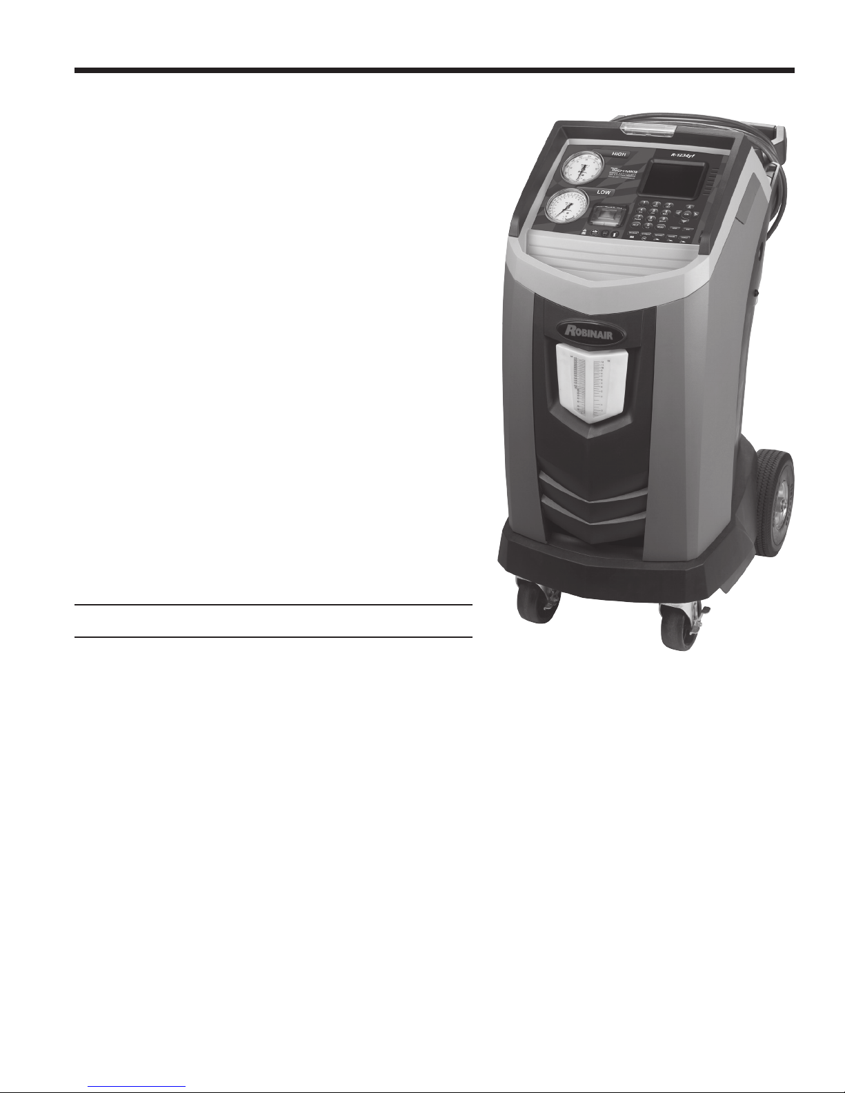
Model: J-52405
R-1234yf A/C Recover, Recycle, Recharge Machine
ROBINAIR.COM 800.533.6127
Page 2

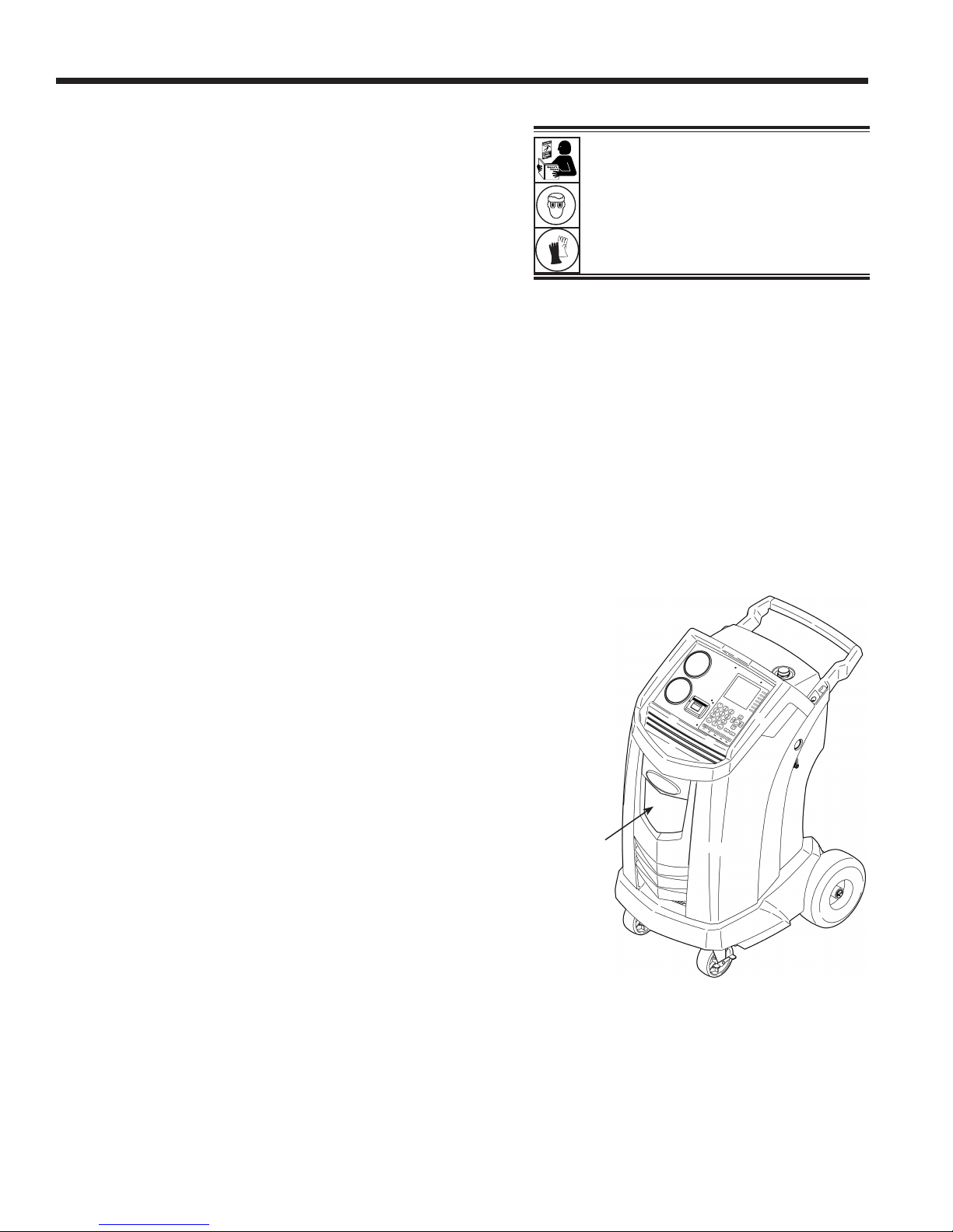
Description: Recover, recycle, and recharge machine for use
with R-1234yf equipped air conditioning systems.
PRODUCT INFORMATION
Record the serial number and year of manufacture of this unit for future reference. Refer to the product
identication label on the unit for information.
Serial Number: _______________________________Year of Manufacture: ____________
DISCLAIMER: Information, illustrations, and specications contained in this manual are based on the latest information available at the time
of publication. The right is reserved to make changes at any time without obligation to notify any person or organization of such revisions
or changes. Further, ROBINAIR shall not be liable for errors contained herein or for incidental or consequential damages (including lost
prots) in connection with the furnishing, performance, or use of this material. If necessary, obtain additional health and safety information
from the appropriate government agencies, and the vehicle, refrigerant, and lubricant manufacturers.
Page 3

Table of Contents
Safety Precautions .......................2
Explanation of Safety Signal Words ............... 2
Explanation of Safety Decals. . . . . . . . . . . . . . . . . . . . . 2
Protective Devices ............................. 4
J2843 Requirement Regarding Lubricant ........... 4
Introduction .............................5
Technical Specications ........................ 5
Features ....................................6
Control Panel Functions ........................ 8
Initial Setup Procedure ...................10
Unpack the Accessory Kit ...................... 10
Accessory Kit .............................. 10
Install the Oil Drain Bottle ...................... 10
Power Up the Machine .........................11
Language Selection ............................11
End User License Agreement ....................11
Unit of Measure ...............................11
Dealer Info .................................. 12
Date and Time Setup .......................... 13
Service Vacuum .............................. 13
Tank Fill Adjustment. . . . . . . . . . . . . . . . . . . . . . . . . . . 13
Tank Filling. . . . . . . . . . . . . . . . . . . . . . . . . . . . . . . . . . 14
Register the Machine. . . . . . . . . . . . . . . . . . . . . . . . . . 15
Setup Menu ............................16
Setup Menu Optional Items ..................... 16
Beeper Setting ............................. 16
BlueTooth Conguration ...................... 16
Pairing a U-Scan to a Robinair AC Recover, Recycle,
and Recharge Machine ...................... 16
Viewing Serial Number of Paired VCI ........... 17
Un-pairing a VCI ............................ 17
Ethernet Settings ........................... 17
Default Charge Target ....................... 17
Legal .................................... 17
System Information ......................... 17
Test Network Connection ..................... 17
Date Format Selection ....................... 17
WiFi Conguration .......................... 18
WiFi Conguration for Hidden Networks ......... 19
Database ................................... 20
VIN Entry ................................... 21
A/C Pressure Snapshot ........................ 21
A/C Service Function ....................22
Printouts ...................................22
At the End of Every Function .................. 22
After the Service is Completed and Exited ........ 22
Hose Equalize ...............................23
System Flush ................................ 24
Setup .................................... 24
Operating Instructions ....................... 25
Service Job Data ............................. 26
Procedure to Move Job Records ............... 27
Procedure to Copy Job Record ................ 27
Automatic. . . . . . . . . . . . . . . . . . . . . . . . . . . . . . . . . . . 28
Recovery ...................................30
Vacuum .................................... 31
Charge ..................................... 32
Hose Flush .................................34
Unit Maintenance ........................35
Tank Filling. . . . . . . . . . . . . . . . . . . . . . . . . . . . . . . . . . 35
Maintain Vacuum Pump Oil ..................... 36
Maintain Filter ............................... 37
Check Remaining Filter Capacity ............... 37
Replace the Filter and Sample Hose Assembly .... 37
Refrigerant Identier ......................... 39
Calibration Check ............................ 39
Refrigerant Management ....................... 40
Air Purge Info. . . . . . . . . . . . . . . . . . . . . . . . . . . . . . . . 40
Backlight ................................... 40
Replace Service Hoses and/or
Service Couplers ............................. 40
General Maintenance ......................... 41
Maintenance Procedures ................. 42
Replace O2 Sensor in the Refrigerant Identier ..... 42
Tank Fill Hose Filter Service .................... 44
Cleaning the Tank Fill Hose Filter ............... 44
Edit Print Header ............................. 45
Replace Printer Paper ......................... 45
Replacement Parts and Glossary ..........46
Replacement Parts ........................... 46
Glossary ...................................46
Troubleshooting Messages ............... 47
Troubleshooting Procedures ..............49
Setup, Tank Fill, and Background Tank Fill Functions . 49
Display Message: Purity Test Failed ............ 49
Recovery Function or Automatic Function .......... 50
Display Message: Purity Test Failed ............ 50
Recovery Function .......................... 51
Display Message: System Pressure ............ 51
Display Message: Filter Weight XXX LB ......... 51
Display Message: Identier Filter and Sample Tube
May Need Replacement ...................... 51
Vacuum Function ............................. 52
Display Message: Pressure Too High ........... 52
Automatic, System Flush, or Charge Functions ..... 53
Display Message: Insufcient Refrigerant ........ 53
Display Message: Pressure Too High ........... 53
Display Message: Vacuum Time X:XX min ....... 53
Storage and Transportation of Equipment ...54
Storage .................................... 54
Transportation of Equipment .................... 54
Disposal of Equipment ...................55
Disposal of Recycled Materials ..................55
Disposal of the Machine ....................... 55
Disposal of Batteries .......................... 55
581371 REV A
1
Page 4
Safety Precautions
Explanation of Safety Signal Words Used in this Manual
The safety signal word designates the degree, or level, of hazard seriousness.
DANGER: Indicates an imminently hazardous situation which, if not avoided, will result in death or
serious injury.
WARNING: Indicates a potentially hazardous situation which, if not avoided, could result in death or
serious injury.
CAUTION: Indicates a potentially hazardous situation which, if not avoided, could result in minor or
moderate injury.
CAUTION: Used without the safety alert symbol indicates a potentially hazardous situation which, if not
avoided, could result in property damage.
These safety messages cover situations Robinair is aware of. Robinair cannot know, evaluate, or advise as to
all possible hazards. The user must verify that conditions and procedures do not jeopardize personal safety.
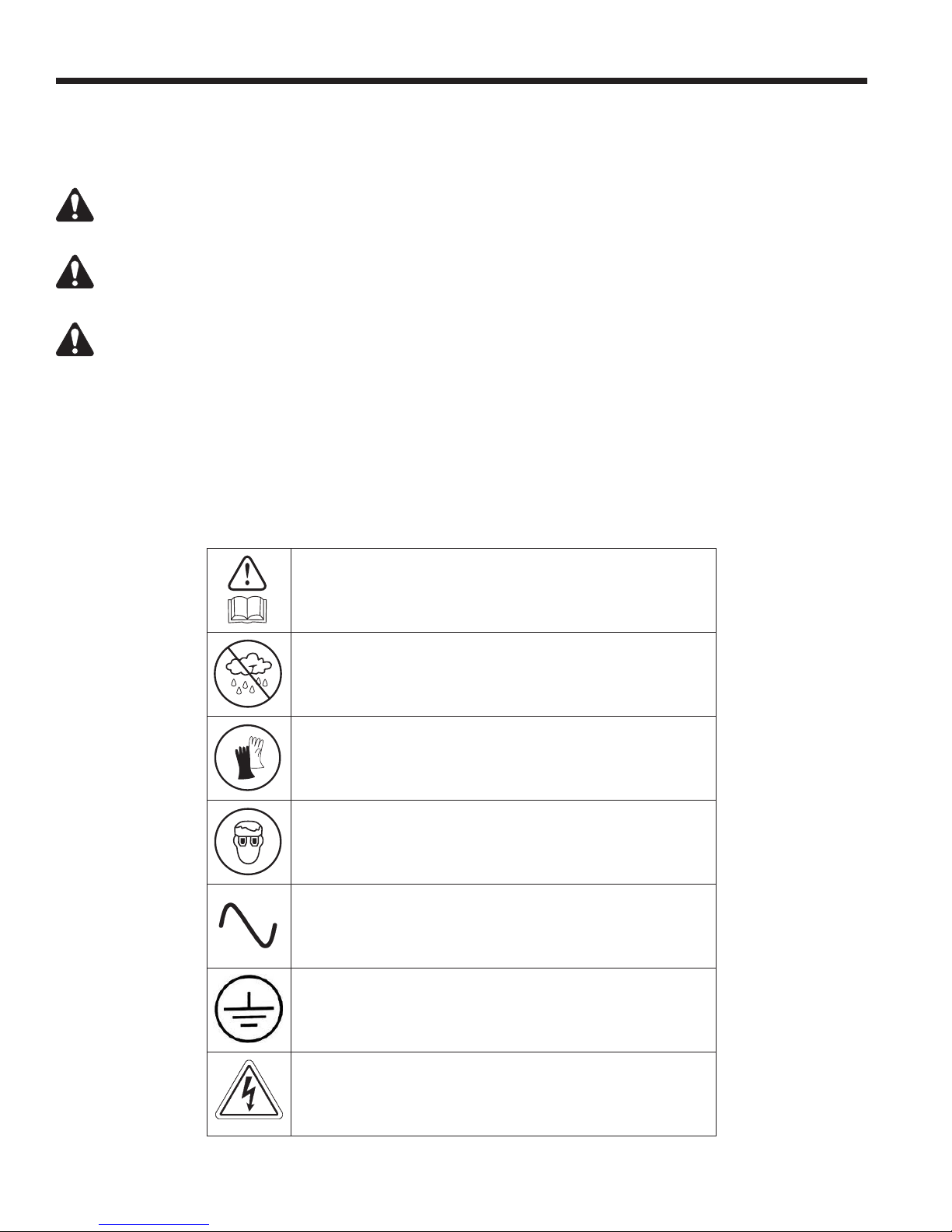
Explanation of Safety Decals Used on the Machine
Carefully read the instructions.
Do not use in open air in case of rain or high humidity.
Wear gloves.
Wear protection goggles.
Alternating voltage.
Grounding protection.
Electrical shock hazard.
2
Page 5
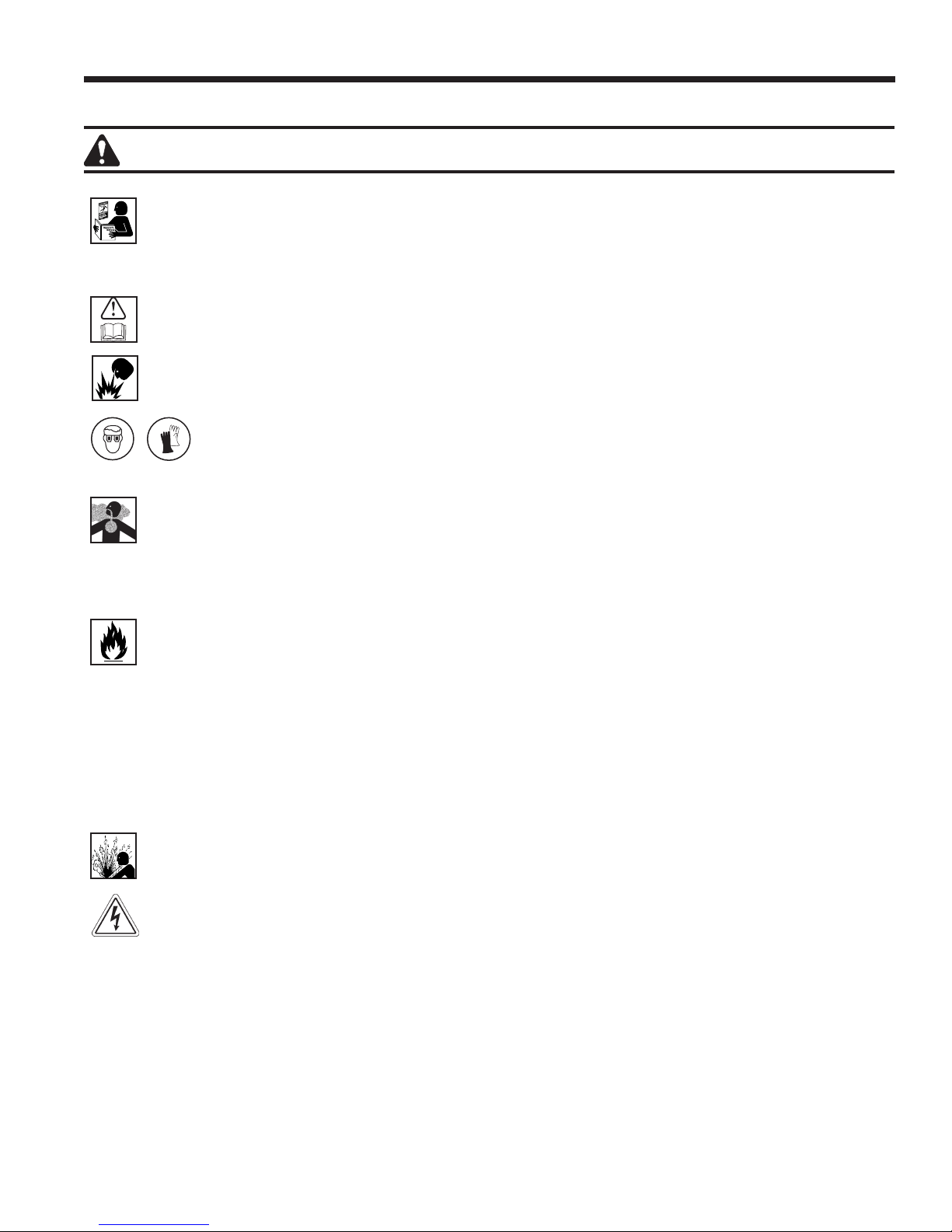
WARNING: To prevent personal injury,
ALLOW ONLY QUALIFIED PERSONNEL TO OPERATE THE MACHINE. Before operating the machine, read
and follow the instructions and warnings in this manual. The operator must be familiar with air conditioning
and refrigeration systems, refrigerants, and the dangers of pressurized components. If the operator cannot
read this manual, operating instructions and safety precautions must be read and discussed in the operator’s
native language.
USE THE MACHINE AS OUTLINED IN THIS MANUAL. Using the machine in a manner for which it was not
designed will compromise the machine and nullify the protections provided.
PRESSURIZED TANK CONTAINS LIQUID REFRIGERANT. Do not overll the internal storage vessel (ISV).
Overlling can cause explosion resulting in personal injury or death. Do not recover refrigerants into nonrellable
containers; use only type-approved rellable containers that have pressure relief valves.
HOSES CAN CONTAIN LIQUID REFRIGERANT UNDER PRESSURE. Contact with refrigerant can
cause personal injury, including blindness and frozen skin. Wear protective equipment, including
goggles and gloves. Disconnect hoses using extreme caution. Ensure the phase is complete before
disconnecting the machine to prevent the release of refrigeration to the atmosphere.
AVOID BREATHING A/C REFRIGERANT AND LUBRICANT VAPOR OR MIST. Exposure can irritate eyes, nose,
and throat. To remove refrigerant from the A/C system, use only equipment certied for the type of refrigerant
being removed. Use the unit in locations with mechanical ventilation that provides at least four air changes per
hour. If accidental system discharge occurs, ventilate the work area before resuming service.
DO NOT DISPERSE REFRIGERANT INTO THE ENVIRONMENT. Prevent the possible presence of refrigerant
in the working environment.
TO REDUCE THE RISK OF FIRE, do not use the machine in the vicinity of spilled or open containers of
gasoline or other ammable substances.
TO REDUCE THE RISK OF FIRE, do not use an extension cord. An extension cord can overheat and cause
re. If an extension cord must be used, use the shortest possible cord with a minimum size of 14 AWG.
TO REDUCE THE RISK OF FIRE, do not use the machine in the vicinity of ames and hot surfaces. Refrigerant
can decompose at high temperatures and free toxic substances to the environment that can be noxious to
the user.
TO REDUCE THE RISK OF FIRE, do not use the machine in environments containing explosive gases or vapors.
TO REDUCE THE RISK OF FIRE, protect the machine from conditions that can cause electrical failure or
other hazards relating to ambient interaction.
CAUTION—DO NOT PRESSURE TEST OR LEAK TEST EQUIPMENT AND/OR VEHICLE AIR CONDITIONING
SYSTEMS WITH COMPRESSED AIR. Some mixtures of air and refrigerant have been shown to be combustible
at elevated pressures. These mixtures, if ignited, can cause injury or property damage.
HIGH VOLTAGE ELECTRICITY INSIDE THE MACHINE HAS A RISK OF ELECTRICAL SHOCK. Exposure
can cause personal injury. Disconnect power before servicing the machine.
Safety Precautions
NEVER LEAVE THE MACHINE LIVE IF AN IMMEDIATE USE IS NOT SCHEDULED. Disconnect the electrical
supply before a long period of inactivity or before internal maintenance is performed.
DO NOT MODIFY THE PRESSURE RELIEF VALVE OR CHANGE THE CONTROL SYSTEM SETTINGS.
Using the machine in a manner for which it was not designed will compromise the machine and nullify the
protections provided.
Additional health and safety information can be obtained
from refrigerant and lubricant manufacturers.
581371 REV A
3
Page 6
Safety Precautions
CAUTION : To prevent equipment damage,
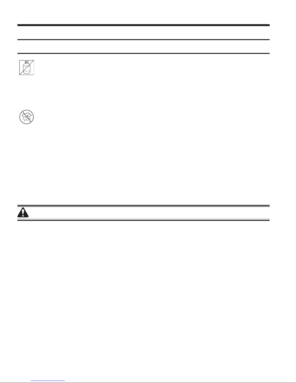
TO PREVENT CROSS-CONTAMINATION, USE THIS MACHINE WITH R-1234YF REFRIGERANT ONLY.
The machine is equipped with special connectors to recover, recycle, and recharge only R-1234yf refrigerant.
Do not attempt to adapt the machine for another refrigerant. Do not mix refrigerant types through a system
or in the same container; mixing of refrigerants will cause severe damage to the machine and the vehicle air
conditioning system.
DO NOT USE THIS MACHINE IN DIRECT SUNLIGHT. Position the machine far from heat sources, such as
direct sunlight, which can cause excessive temperatures. The use of this machine under normal environmental
conditions (10°C to 50°C) keeps pressures under reasonable limits.
DO NOT USE THIS MACHINE OUTDOORS DURING RAIN OR HIGH HUMIDITY. Protect the machine from
conditions that can cause electrical failure or other hazards relating to ambient interaction.
DO NOT USE THIS MACHINE IN AREAS WHERE THERE IS A RISK OF EXPLOSION.
SET UP THE MACHINE ON AN EVEN SURFACE AND UNDER SUFFICIENT LIGHTING. LOCK THE FRONT
WHEELS, AND DO NOT SUBJECT THE MACHINE TO VIBRATION.
Additional health and safety information can be obtained
from refrigerant and lubricant manufacturers.
Protective Devices
The machine is equipped with the following protective devices:
• Over pressure valves.
• A maximum pressure switch stops the compressor when excessive pressure is sensed.
WARNING: Tampering with these protective devices could result in serious injury.
J2843 Requirement Regarding Lubricant
Only new lubricant, as specied by the system manufacturer, shall be installed in the MAC (Mobile Air
Conditioning) system. Lubricant removed from the system and / or the equipment shall be disposed of in
accordance with applicable federal, state, and local procedures and regulations.
4
Page 7
This machine is designed and certied to SAE J2843 HFO1234yf Recovery / Recycling / Recharging Equipment for
Flammable Refrigerants for Mobile Air-Conditioning Systems.
The machine is designed to recover and recycle R-1234yf
refrigerant, evacuate air after the system has been open, and
recharge refrigerant.
Other functions include system ush, diagnostic pressures, and
retention of service data by vehicle VIN for recall and printout.
The machine is a single-pass system (i.e. refrigerant ows
through a lter once) that meets SAE J2099 specications
for recycled refrigerant. The machine also meets oil crosscontamination requirements for high-voltage system charge.
Follow recommended service procedures for the containment
of R-1234yf.
Note: R-1234yf systems require special oils. Refer to the A/C
system manufacturer’s service manual for oil specications.
Introduction
Technical Specications
Compressor ..............................1/3 HP
Dimensions .................107 cm x 56 cm x 80 cm
Filter Capacity .............................150 kg
Humidity .......90°F (32.2°C), 86% RH non-condensing
Pressure Gauges .......................Ø 100 mm
Maximum Pressure . . . . . . . . . . . . . . . . . . . . . . . . . 30 bar
Noise .................................<70 dB(A)
Nominal Voltage ................103V to 127V, 60 Hz
Oil Drain Bottle ............................355 ml
Operating Temperature ...50°F to 122°F (10°C to 50°C)
Power Consumption ...................... 1150 VA
Pump Free-Air Displacement ........1.5 CFM (42 l/m)
Service Hoses ..............275 cm (9 ft) / SAE J2888
Tank Capacity ....................9.50 kg (20.94 lb.)
Weight ............................107 kg (235 lb.)
581371 REV A
5
Page 8
Introduction
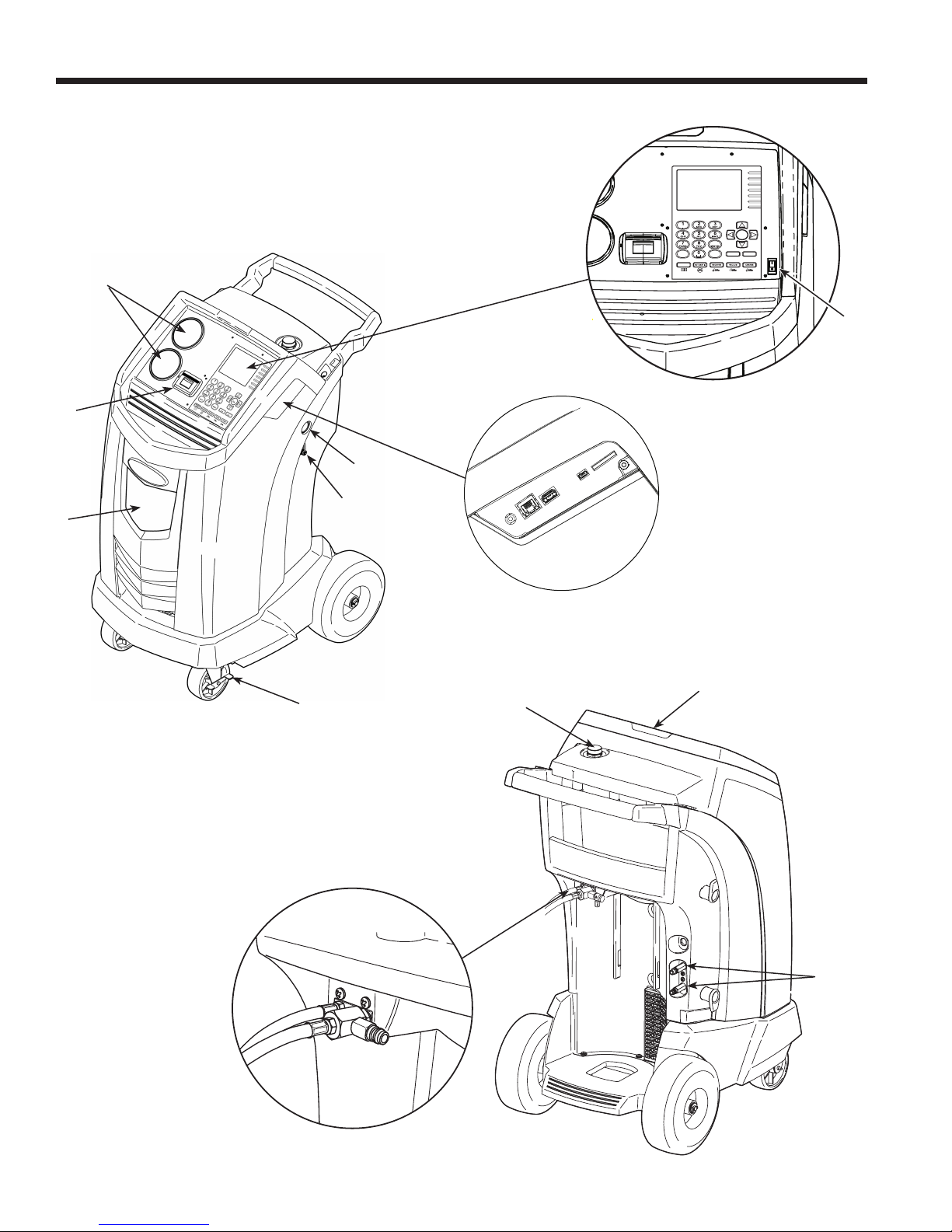
Features
3
2
4
OK
9
HELP MENU
DATABASE
STOP ESC
5
7
1
8
6
10
9
11
6
13
12
Page 9

Introduction
Item
No.
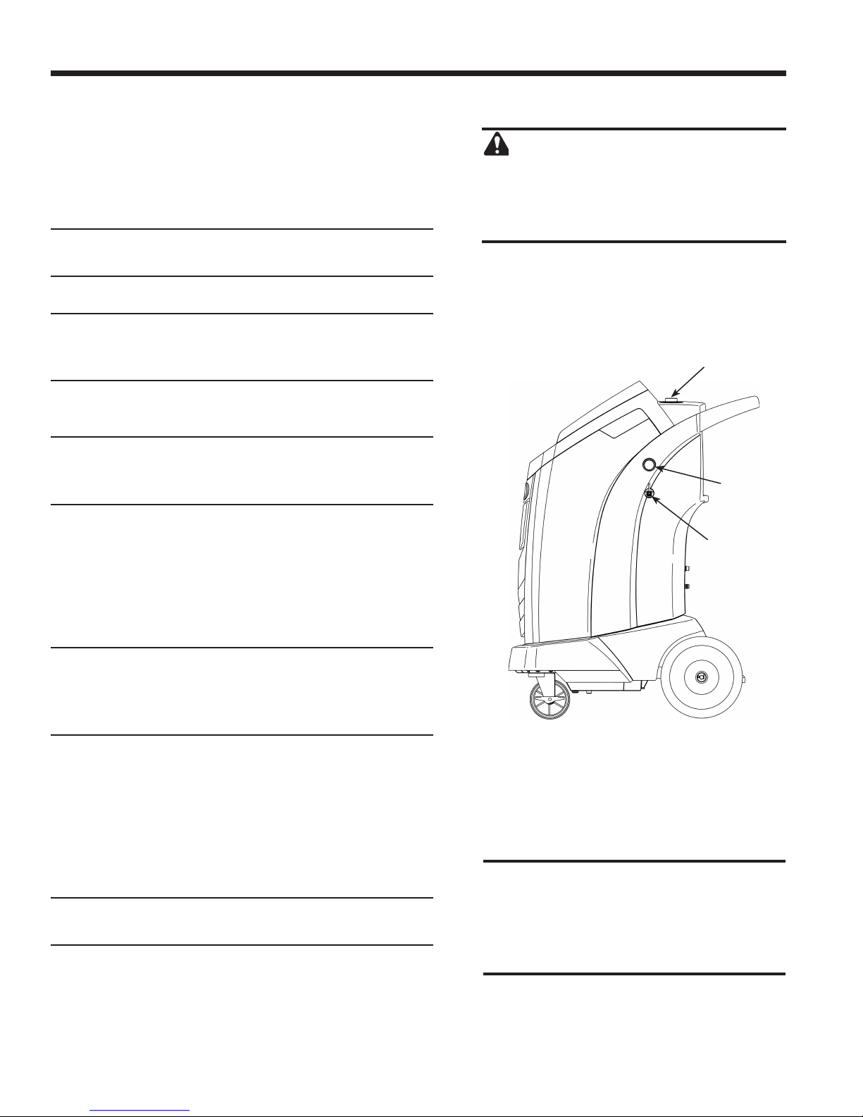
1 Oil Drain Bottle
2 Printer
3 Low-side (blue) and High-side (red) Manifold Gauges
4 Graphic Display and Keypad
5 Power ON / OFF Switch
6 Audio, Ethernet, USB, Mini-USB, and SD Card Connections
7 Vacuum Pump Oil Sight Glass
8 Vacuum Pump Oil Drain Fitting
9 Wheel Lock
10 Visual Alert
Description
11 Vacuum Pump Oil Fill Cap and Port
12 Contaminant Recovery Port
13 Service Hose Storage Ports
581371 REV A
7
Page 10
Introduction
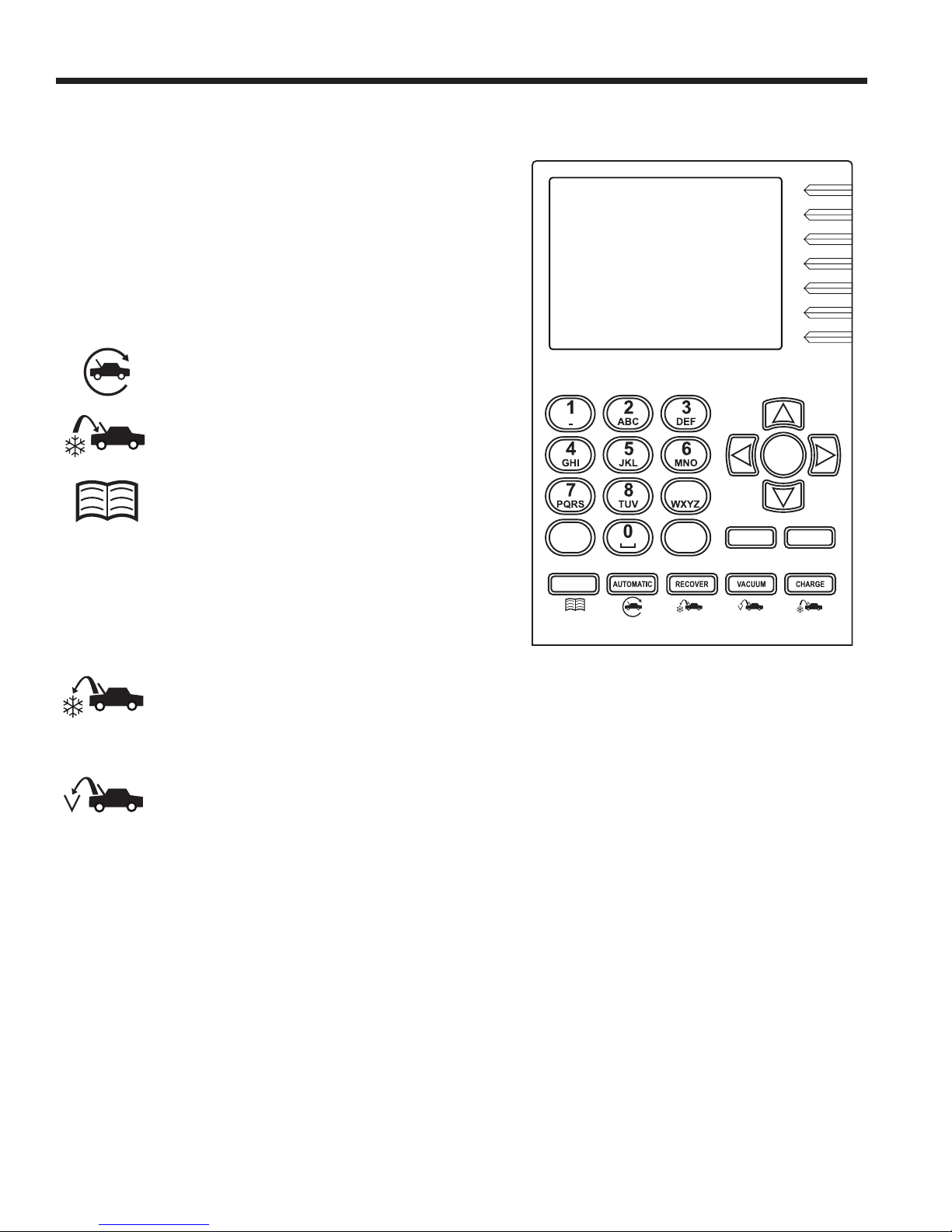
Control Panel Functions
ARROW UP moves selection of a menu item to the previous
item; turns up audio volume.
ARROW DOWN moves selection of a menu item to the
following item; turns down audio volume.
ARROW RIGHT scrolls to next screen; fast forwards
the video.
ARROW LEFT scrolls to previous screen; rewinds the video.
AUTOMATIC activates a menu to set up an
automatic recovery / vacuum / leak test /
charge sequence.
CHARGE activates a sequence to charge
the vehicle A/C system with a programmed
amount of refrigerant.
DATABASE
charge capacity by vehicle model.
supplies information regarding
OK
9
ESC returns the test sequence to the previous screen; or
answers a query.
HELP displays information related to the current display.
MENU accesses additional functions and setup parameters.
OK highlights the menu item, answers a query, or starts
the video.
RECOVER activates a sequence to recover
refrigerant from the vehicle A/C system.
STOP interrupts the active function. Press once to pause,
twice to terminate.
VACUUM activates a sequence to pull a deep
vacuum on the vehicle A/C system to remove
air and moisture.
HELP MENU
DATABASE
Control Panel Keypad
STOP ESC
8
Page 11
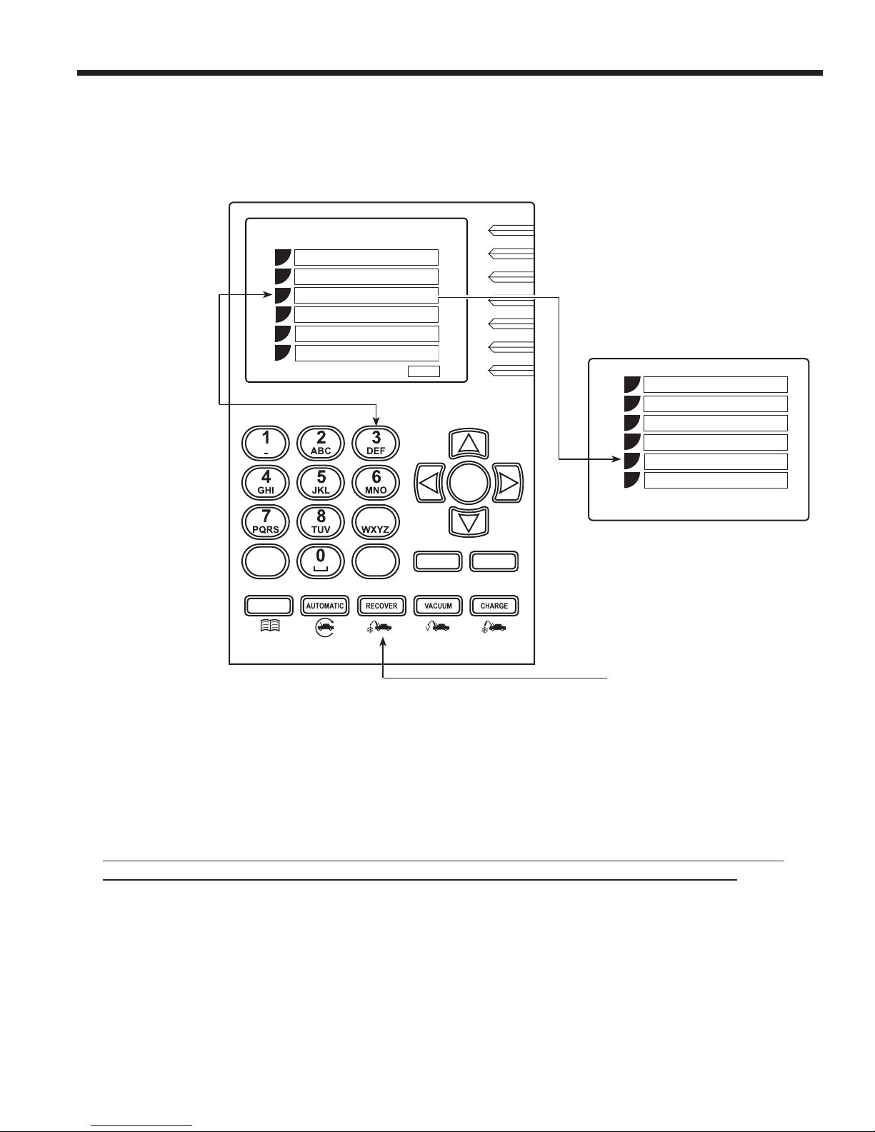
Introduction
Press the number
on the keypad
that matches the
number of the
function to access.
1
2
3
4
5
6
Unit Setup
Unit Maintenance
A/C Service Function
Database
Update
Service Menu
9
HELP MENU
DATABASE
ESC
STOP ESC
OK
1
2
3
4
5
6
Hose Equalize
System Flush
Service Job Data
Automatic
Recovery
Vacuum
In this example,
another way to
select Recovery
is by pressing the
RECOVER button on
the control panel.
ESC
Notes regarding main menu items not outlined in this manual:
• Update - use this menu item to update application, database, or URL via WiFi.
To use the WiFi features, the network rewall must allow access to:
http://connectedservicesvc-equip3.bosch-automotive.com/api/RepairResults/upload and
http://9e864a0ddceb616e594a-77285b2f7a214aa453b5113bdf793358.r48.cf1.rackcdn.com
• Service Menu - for service centers’ use only
• Production Menu - for manufacturer’s use only
• Administrator - for manufacturer’s use only
581371 REV A
9
Page 12
Initial Setup Procedure
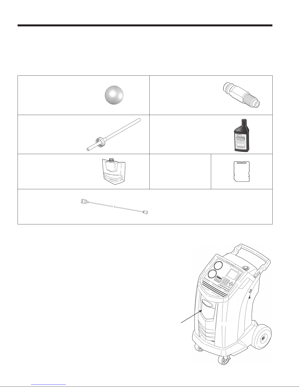
Unpack the Accessory Kit
Unpack the accessory kit from the box, and remove the plastic packaging.
Accessory Kit
Calibration Check
Weight
Cap and Filler Tube
Oil Drain Bottle SD Card
External DLC Cable
Tank Fill Hose
Adapter
Vacuum Pump Oil
16 oz.
Pouch containing SDSs, EPA information, MACS
information, and a service center list.
Install the Oil Drain Bottle
Hold the oil drain bottle straight and insert the connector into
the hole behind the shroud until it snaps into place.
10
Oil
Drain
Bottle
Page 13

Initial Setup Procedure
Important:
• This procedure can take several hours. Perform
this initial setup procedure BEFORE the machine
is needed for its rst vehicle A/C service.
• During initial setup, the machine prompts through
the following steps. Any changes to these settings
after the initial setup can be completed through the
Unit Setup menu.
Power Up the Machine
1. Unwind the power cord from the handle, and plug it into
a correct voltage, grounded outlet.
2. Position the machine so the plug and the main power
switch are within easy access of the operator. Verify the
fan vents on the rear of the machine are not obstructed.
3. Lock the front wheels.
4. Turn on the main power switch.
Language Selection
CAUTION: The machine is programmed
to run the setup procedure as outlined
here. To prevent personal injury, do NOT
operate the machine without the oil ll port
plug installed, because the vacuum pump
is pressurized during normal operation.
The operator selects the language for screen prompt
displays.
1. Use the UP or DOWN arrow key to toggle through the
available languages.
2. Press OK to set the selected language.
End User License Agreement
Approve the End User License Agreement to proceed with
the initial setup.
Unit of Measure
Program the machine to display units of measure in
kilograms or pounds. The default display is English.
Note: If English is selected, weights will be displayed in
metric units (per SAE standard J2843); pressures and
temperatures will be displayed in English units.
1. Use the UP or DOWN arrow key to toggle Metric or
English units.
2.
Press OK to choose the displayed unit of measure.
581371 REV A
11
Page 14
Initial Setup Procedure
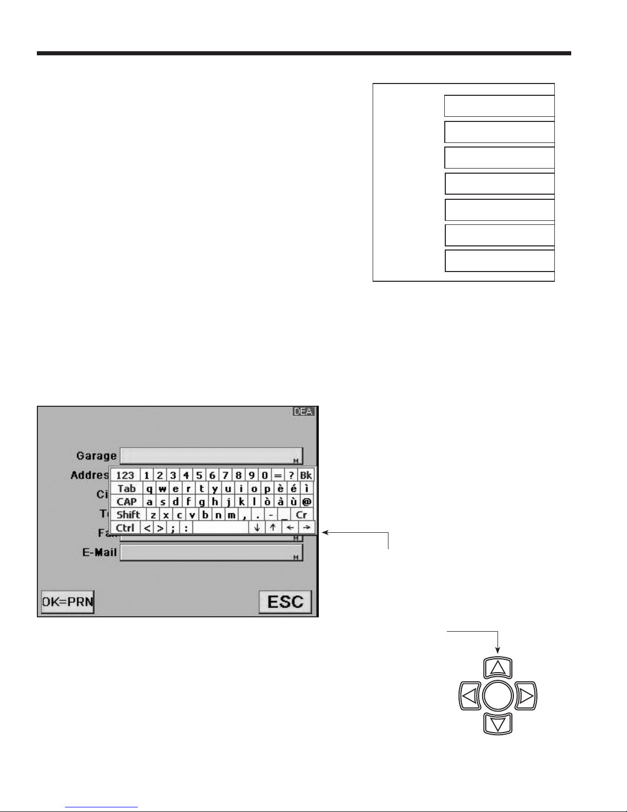
Dealer Info
This machine has the capability to print out recovery, vacuum,
charge, and ush information for each vehicle tested. A printout
may be obtained any time the display screen shows OK=PRN.
The information entered in the ll elds on the Dealer Info
screen will appear on each printout.
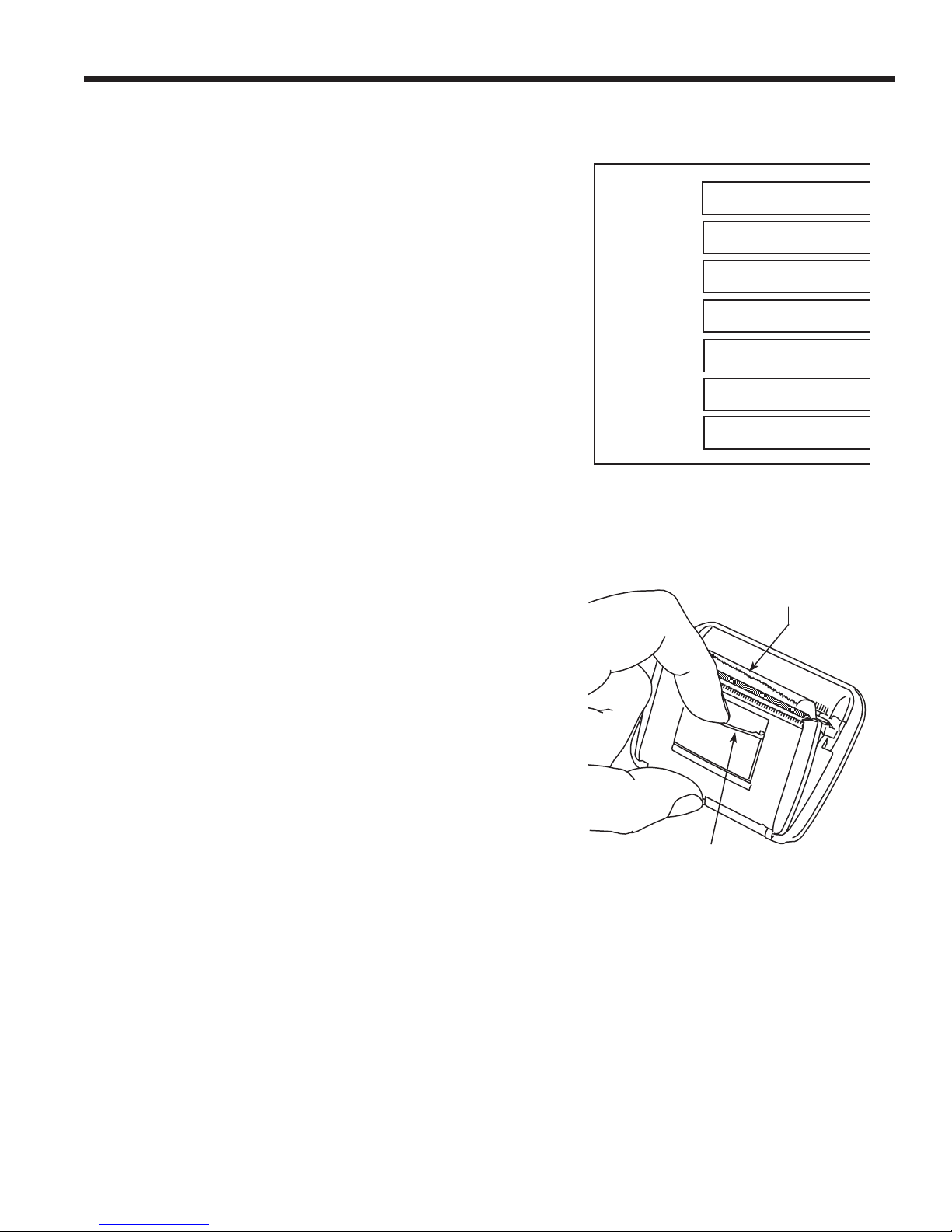
1. The cursor is blinking in the Dealer Code eld. Refer to
Figure 1.
2. Press the MENU key and a virtual keyboard appears as
shown in Figure 2. Note: A standard USB keyboard may be
connected to the machine and used to enter information.
3. Use the arrow keys on the machine’s keypad to move
around the keyboard. Press OK to enter a character. The
cursor will move to the next character.
4. Press the MENU key to exit the virtual keyboard. Use the
arrow keys to move to the next eld. Press OK to save
the data once all applicable elds are lled in. Press ESC
when done.
Dealer Code
Garage
Address
City
Tel
Fax
E-mail
Figure 1
Figure 2
12
Use the arrow
keys in the virtual
keyboard to move
the cursor within
the ll eld.
Use the arrow keys
on the machine’s
keypad to move
around the virtual
keyboard.
OK
Page 15

Initial Setup Procedure
Date and Time Setup
The machine is programmed at the factory for the local time
zone using a 24-hr. clock and date.
Note: The date changes only by scrolling through an entire day.
1. Use the LEFT and RIGHT arrow keys to modify the
minutes displayed.
2. Use the UP and DOWN arrow keys to modify the
hour displayed.
3. Press OK to accept the date and time.
Service Vacuum
Follow the prompts to connect the machine’s service hoses to
the storage ports and open the service couplers. The machine
performs a 5-minute vacuum to remove air from its internal
plumbing and the ISV (internal storage vessel).
When prompted, press OK to continue Initial Setup.
Tank Fill Adjustment
The operator can either accept the machine’s preset default
weight of 3.5 kg of refrigerant stored in the internal storage
vessel (ISV), or change the amount to accommodate the
application.
The maximum amount allowed for new refrigerant is 6.8 kg,
which leaves room for additional recovery. The minimum
amount is 1.8 kg.
1. Select TANK FILL ADJUSTMENT from the Unit Setup menu.
2. The machine displays the default amount of refrigerant:
TANK LEVEL
03.500 KG
3. Press OK to accept the default amount, or use the keypad
to enter an amount and press OK.
581371 REV A
13
Page 16
Initial Setup Procedure
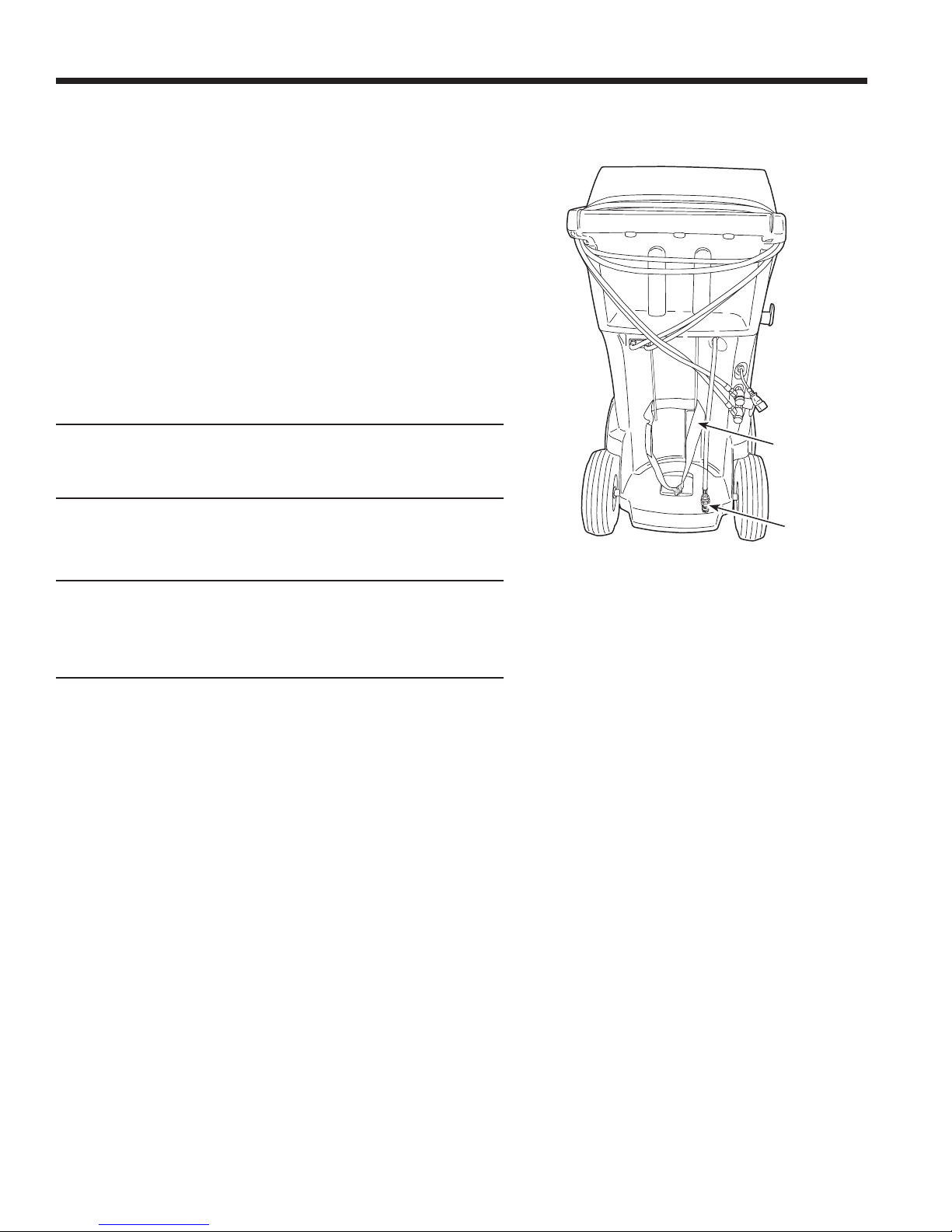
Tank Filling
1. Connect an R-1234yf source tank to the tank ll hose at
the rear of the machine. Hand tighten the tank ll hose.
See Figure 3.
Note: The tank ll hose and the tank access port have
left-hand threads.
2. Open the tank valve.
3. Mount the source tank on the shelf at the rear of the
machine, oriented to supply liquid refrigerant to the
connection. Tighten the holding strap around the source
tank. Verify the tank does not restrict air ow from the vent.
4. The machine displays
FILL AMOUNT
XX.XXX
CONNECT SOURCE TANK TO FILL HOSE
5. Press OK. The machine checks the refrigerant in the
source tank to verify it is R-1234yf and not contaminated,
and displays the following screens:
WARM UP
CALIBRATION IN PROGRESS
GAS IDENTIFY
REFRIGERANT PURITY ACCEPTABLE
After completing the above steps, the machine begins
lling the internal storage vessel (ISV).
6. The machine automatically stops when the preset tank
ll level is reached or the source tank is empty. To stop
tank ll before the preset level is reached, select ESC;
press OK to continue.
7. If using a non-rellable tank, the machine must display
SOURCE TANK EMPTY before the tank may be discarded.
Strap
Tank Fill
Hose
Figure 3
14
Page 17
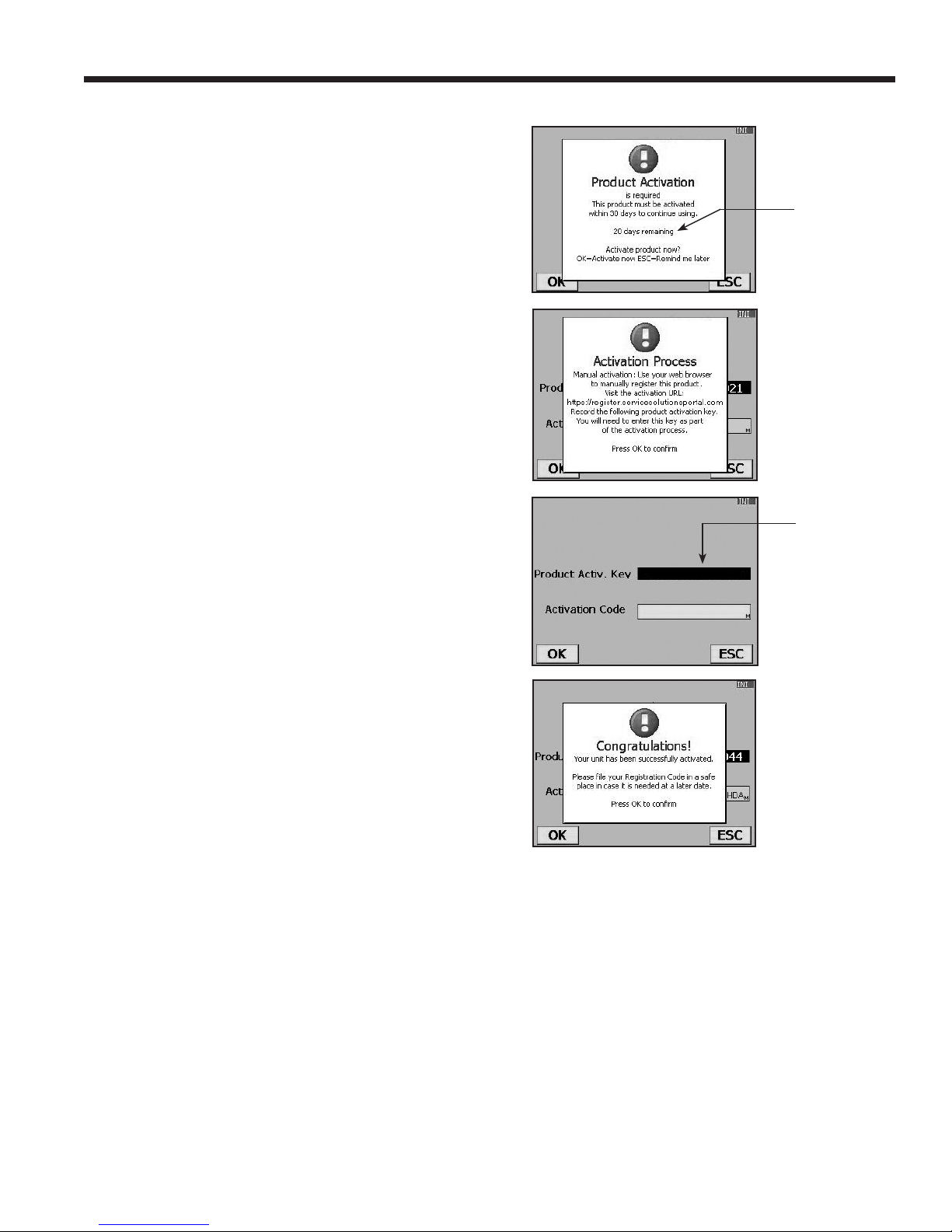
Register the Machine
When the Product Activation screen appears on the
display, follow on-screen prompts to register the machine.
1. Open a web browser on a personal computer. Enter
the web address shown in the Activation Process
screen on the machine.
Enter your user name and password, and log in to
the website.
First-time users, click the REGISTER button to create
a user name and password.
2. On the machine, press OK. The machine displays elds
for the product activation key and an activation code.
3. Enter the product activation key into the correct eld
on the web page. This generates an activation code.
4. Enter the activation code into the machine display
and press OK.
Note: Capitalization is required. A standard USB
keyboard can be connected to the machine to enter
information.
5. Record the product activation key and code and le
it in a secure place.
Initial Setup Procedure
Failure to
register and
activate the
machine
within 30
days of initial
startup will
cause the
machine to
lock out and
no longer
function.
The Product
Activation
Key will be
displayed in
this eld.
6. Press OK.
581371 REV A
15
Page 18
Setup Menu
Setup Menu Optional Items
Many of the functions included in the Initial Setup
Procedure can also be accessed through the
Setup Menu. Additional Setup Menu functions are
explained here.
1. Press the MENU key.
2. Select UNIT SETUP from the menu listings.
Beeper Setting
1. Select BEEPER SETTING from the Unit Setup
menu.
2. Press the OK button to toggle the audio “beep”
OFF and ON.
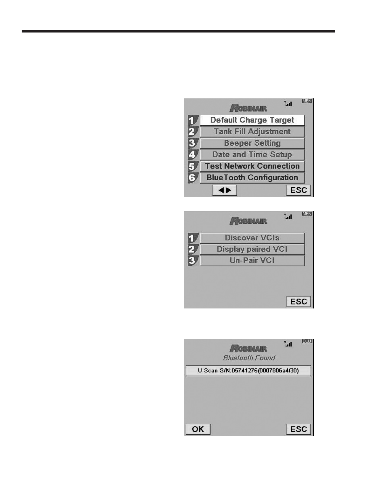
BlueTooth Conguration
This menu selection programs the machine to discover
and pair with a U-Scan™ VCI (Vehicle Communication
Interface).
• Discover and list BlueTooth devices.
Pairing a U-Scan to a Robinair AC Recover,
Recycle, and Recharge Machine
1. Plug the U-Scan into the vehicle OBDII connector.
2. Select the BLUETOOTH CONFIGURATION
option from the setup menu.
3. Select DISCOVER VCIS and press OK
• Screening eliminates all but U-Scan. There is a limit
of one pairing.
• Pairs U-Scan with the machine. Information will be
saved so future pairings are automatic.
• Option to see serial number and other information
from the paired VCI.
• Un-pair an existing paired VCI. Information will be
deleted for future pairings.
4. Follow the on-screen instructions. At the end of
the discovery process, the screen will display a
list of the VCIs that were discovered.
16
Page 19
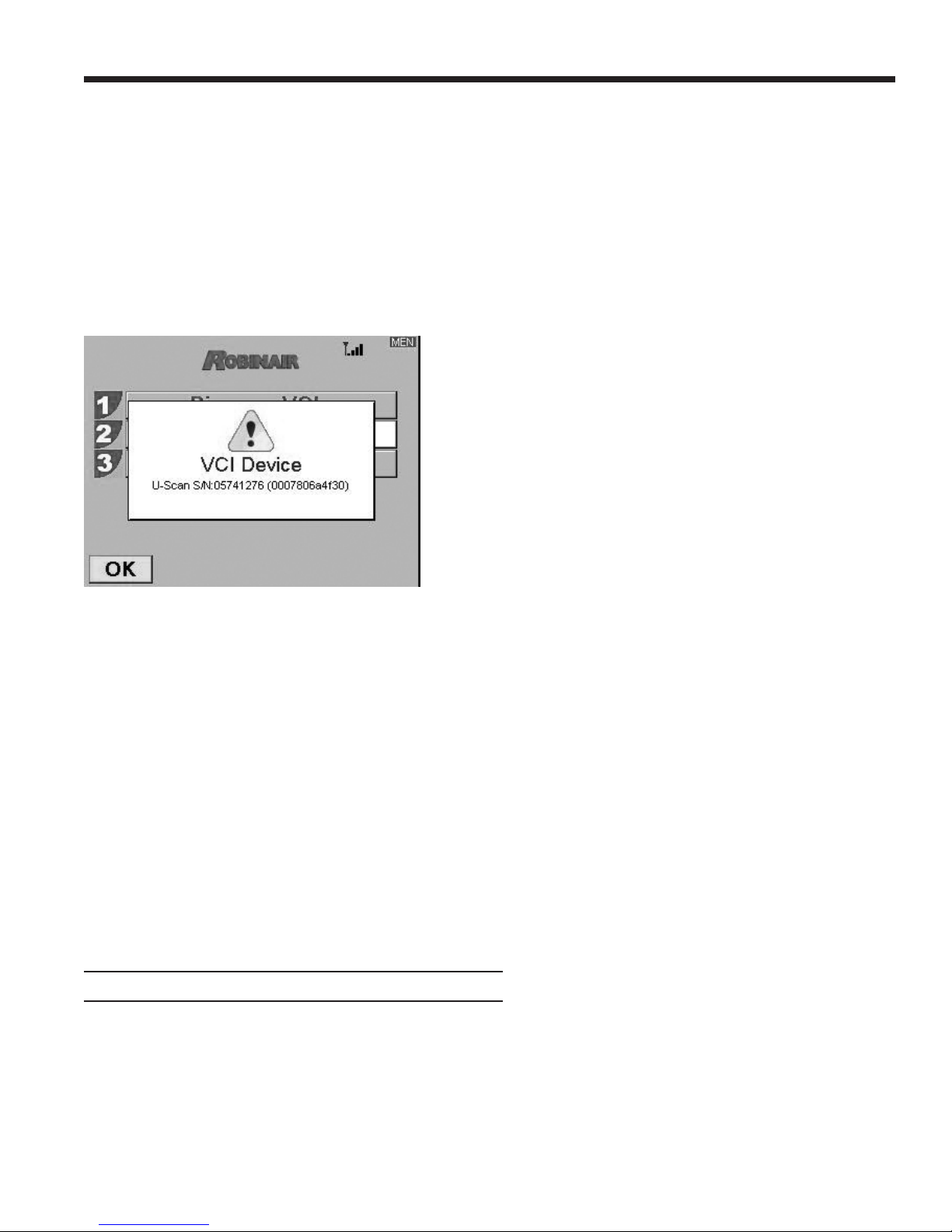
Setup Menu
5. Select the appropriate VCI from the list and press
OK. The pairing process will take several seconds.
Note: The serial number of the U-Scan VCI is located
on the U-Scan packaging.
Viewing Serial Number of Paired VCI
Select Display Paired VCI and press OK. The screen
will display the serial number of the VCI with which it is
currently paired.
Legal
This menu selection displays the end user
license agreement.
System Information
Selecting this menu item displays the revision
level, serial number, and other information about
the software and machine.
Test Network Connection
The information from this menu selection can be
used to troubleshoot network connections.
The MAC address of the WiFi card can be viewed
from this menu.
Date Format Selection
Select the display order for the basic components of
the calendar year - day, month, and year. Press OK.
Un-pairing a VCI
Select Un-Pair VCI and press OK. Follow the on-screen
instructions.
Ethernet Settings
Enable or disable DHCP for Ethernet port.
Default Charge Target
Use this menu item to change the default charge amount
that appears on the charge programming screen.
1. Select DEFAULT CHARGE TARGET from the Unit
Setup menu.
2. The machine displays the current default charge
amount:
0.000 KG
3. Press OK to accept the default amount, or use the
keypad and arrow keys to change the amount. Press
OK to continue or ESC to quit.
581371 REV A
17
Page 20

WiFi Conguration
Use this Setup Menu option to program the machine to discover
and connect to a wireless network. Software updates can be
received in this manner.
Note: The WiFi signal strength indicator is displayed at the standby screen when the machine is connected to a WiFi network.
1. Press the MENU key and select WiFi Conguration from
the Unit Setup menu.
2. Select Search Networks.
3. Use the UP or DOWN arrow to select a WiFi network.
Press OK.
4. A passcode prompt appears:
• for WPA / WPA2 – enter the passcode
• for WEP – the following extra characters are required:
-10 unit WEP key – 1+0x[10-digit key]
[index=1,40-bit(10-digit hexadecimal)]
-5 character WEP key – 4+[5-character key]
[index=4, 40-bit(5-char)
-26 digit WEP key – 3+0x[26-digit key]
[index=3, 104-bit(26-digit hexadecimal)
-13 character WEP key – 2+[13-character key]
[index=2, 104-bit(13-char)
For example, for a 104-bit WEP key, the format is
the following:
1+0x[26 hexadecimal character key]
Denition:
1 = key index
+ = key index delimiter
0x = hexadecimal entry indicator
Note: On the R-1234yf A/C Recover / Recycle / Recharge
Machine, the ‘+’ character is one of the multi-tap keys
under ‘1’.
18
Page 21
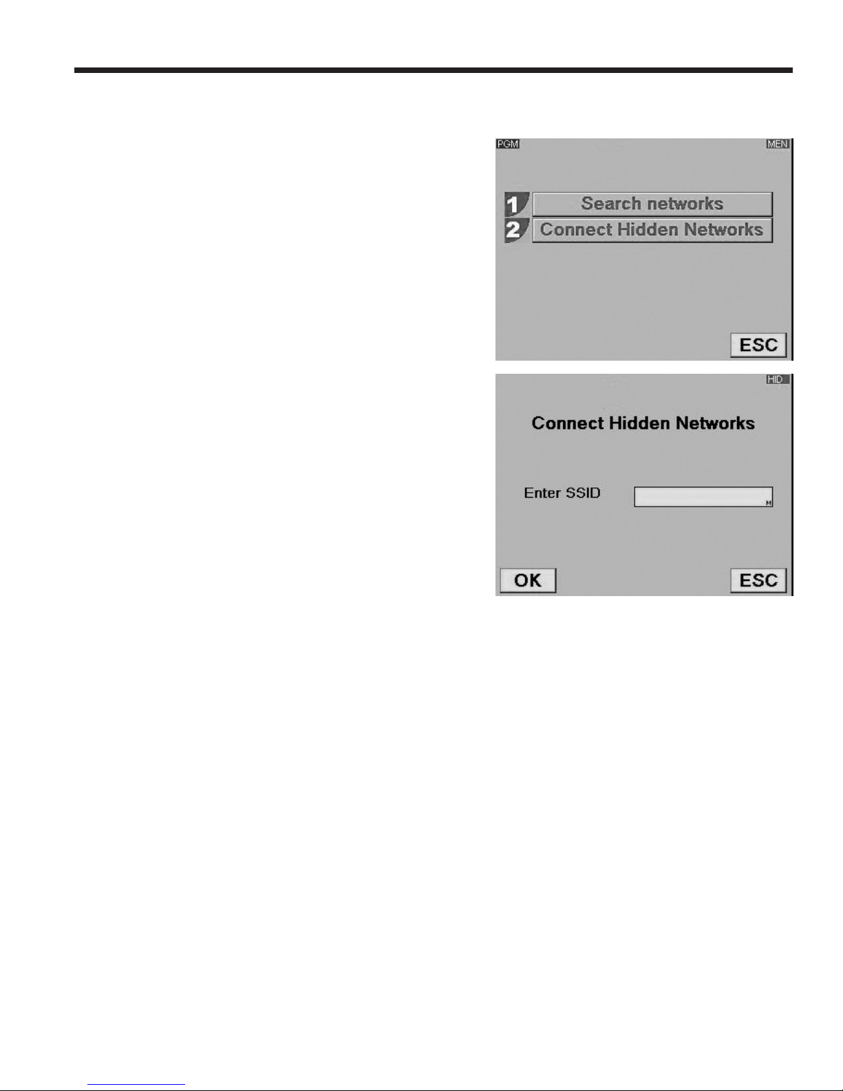
WiFi Conguration for Hidden Networks
1. Press the MENU key and select WiFi Conguration from
the Unit Setup menu.
2. Select Connect Hidden Networks.
3. Enter the SSID of the network and press OK.
581371 REV A
19
Page 22
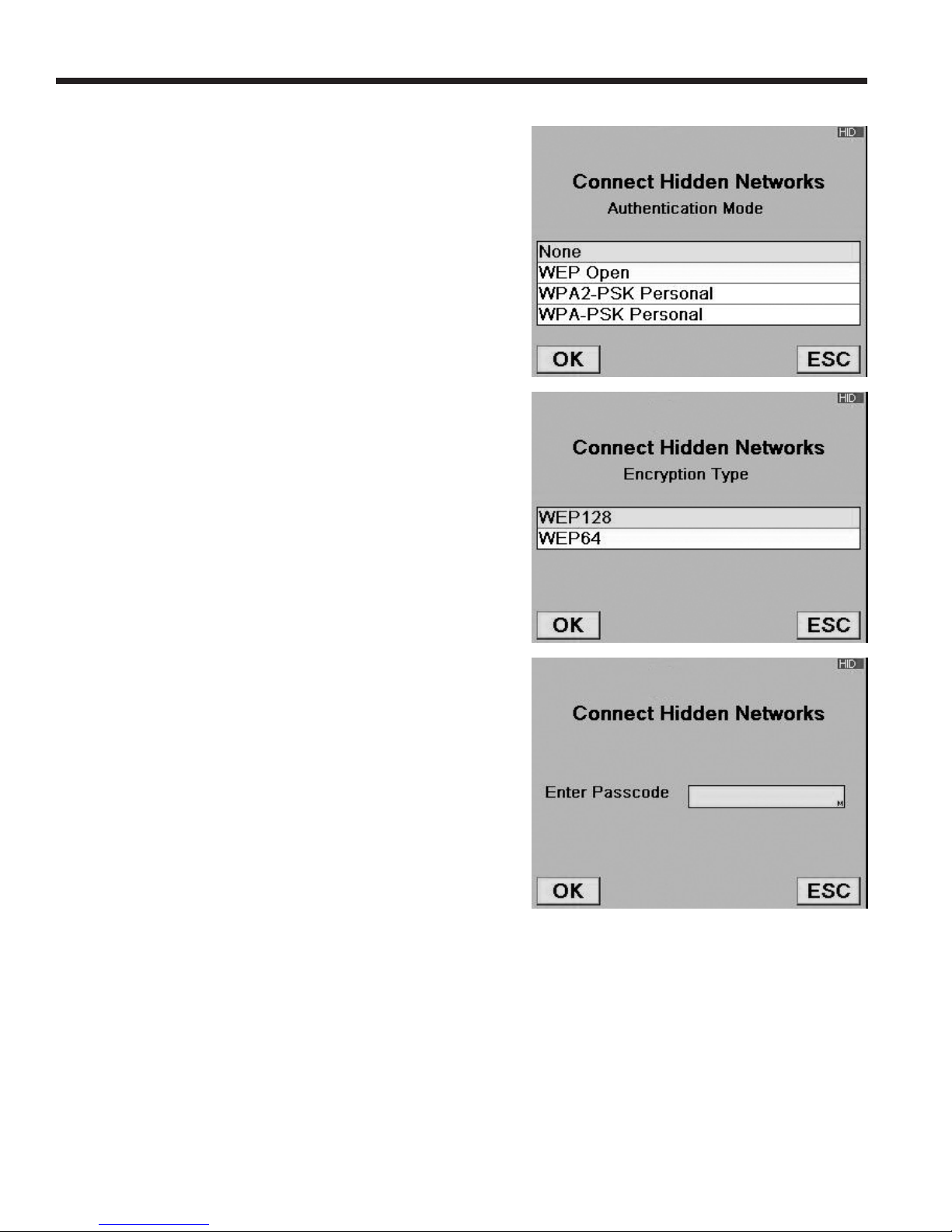
Setup Menu
4. Select the authentication mode of the network and press OK.
5. Select the encryption type for the network and press OK.
6. A passcode prompt appears:
• for WPA / WPA2 – enter the passcode
• for WEP – the following extra characters are required:
-10 unit WEP key – 1+0x[10-digit key]
[index=1,40-bit(10-digit hexadecimal)]
-5 character WEP key – 4+[5-character key]
[index=4, 40-bit(5-char)
-26 digit WEP key – 3+0x[26-digit key]
[index=3, 104-bit(26-digit hexadecimal)
-13 character WEP key – 2+[13-character key]
[index=2, 104-bit(13-char)
For example, for a 104-bit WEP key, the format is
the following:
1+0x[26 hexadecimal character key]
Denition:
1 = key index
+ = key index delimiter
0x = hexadecimal entry indicator
Note: On the R-1234yf A/C Recover / Recycle / Recharge
Machine, the ‘+’ character is one of the multi-tap keys
under ‘1’.
Database
Use this menu option to view refrigerant information by
vehicle.
1. From the Main Menu, select DATABASE.
2. Follow on-screen prompts to select vehicle information.
The screen will display the manufacturer-recommended
refrigerant specications for the vehicle selected.
20
Page 23

VIN Entry
After selecting any A/C Service function, information about
the vehicle and the vehicle identication number (VIN) must
be entered into the machine.
The machine offers various VIN entry methods:
• Wired VCI - connect to the vehicle OBDII port.
• BlueTooth VCI - connect a U-Scan to the vehicle
OBDII port.
Note: The BlueTooth VIN option will only appear if a
U-Scan has been paired to the A/C machine.
• Manual Entry - Use the arrow keys to select a eld, and
use the virtual keypad to enter information.
VIN entry will be used to determine vehicle and service
information using the database.
The information that is entered in this menu item is saved in
Service Job Data.
Setup Menu
A/C Pressure Snapshot
The A/C Pressure Snapshot function is used to capture
vehicle system operating pressures. The captured data
may be viewed, printed, or exported to SD card as part of a
service record.
The following values are captured:
• System high-side pressure
• System low-side pressure
• Ambient temperature
• Ambient humidity
At the start of the RECOVER and AUTOMATIC processes,
the option to perform an A/C Pressure Snapshot to capture
the pre-service operating conditions is given. Again, at the end
of the CHARGE and AUTOMATIC processes, the option is
given to perform the function to allow post-service operating
conditions to be captured.
While the data may be printed at the time of capture, it will also
be stored, printed, or exported with the service record created
for the AUTOMATIC, RECOVER, or CHARGE process.
After the A/C Pressure Snapshot function is completed, the
machine will perform a hose equalization and hose clear as part
of the CHARGE or AUTOMATIC function. This is necessary
to reduce charge loss due to the A/C Pressure Snapshot.
581371 REV A
21
Page 24

A/C Service Function
Printouts
At the End of Every Function
Data for the most recently completed function can be printed
from the results screen by pressing OK on the machine’s
control panel. See Figure 4.
After the Service is Completed and Exited
A summary of the complete service can be printed from
Service Job Data:
1. Press MENU on the machine’s control panel.
2. Select AC SERVICE FUNCTION and then SERVICE
JOB DATA.
3. The choices are:
• VIEW JOB RECORD — a list of VINs is displayed.
Use the UP or DOWN arrow to highlight the VIN for
which to print service data.
Press OK to print data for
the function just completed.
Figure 4
• MOVE JOB RECORD — follow the prompts for this
option to transfer all records to an SD card. The most
recent 100 records will also be retained in Service
Job Data.
• SEND JOB RECORD — follow the prompts for this
option to transfer all records to a server. The most
recent 100 records will also be retained in Service
Job Data.
• COPY JOB RECORD — see “Service Job Data” on
page 26.
Note: Job records must be transferred to a PC for permanent
storage. The SD card will be erased if left in the A/C machine
during a web update.
Note: Refer to “Service Job Data” on page 26.
22
Page 25

Hose Equalize
A/C Service Function
This A/C Service Function menu item directs the user through
clearing the service hoses after running the A/C system to
perform diagnostics. Use this function when the service
hoses were connected, but no refrigerant was charged into
the system.
Following hose equalization prompts prevents leaving part
of the vehicle’s refrigerant charge in the service hoses, a
situation which can cause a loss of A/C performance on
lower-capacity systems.
1. Place the vehicle gear selector in park or neutral, with the
emergency brake ON. Connect the low-side hose to the
A/C system; disconnect the high-side hose.
2. Start the vehicle. Set the A/C system at maximum delivery.
During this operation, the high side and low side are
connected internally, allowing the majority of refrigerant
to be pulled back into the A/C system’s low side.
3. When prompted, disconnect the low-side hose and turn
off the vehicle. Press OK.
4. The machine performs an internal clearing of its plumbing,
and sounds an alarm when complete. Press OK to exit.
1
2
3
4
5
6
Hose Equalize
System Flush
Service Job Data
Automatic
Recovery
Vacuum
È
ESC
Figure 5
Screen 1 of the A/C Service Function Menu
581371 REV A
23
Page 26
A/C Service Function
System Flush
This machine provides a method of removing oil by forcing
liquid refrigerant through an A/C system, or components of an
A/C system. A special ushing adapter (purchased separately)
accesses the A/C system at the compressor block. After
ushing, the refrigerant is recovered by the machine and
ltered by the recycling circuit, returning it to SAE purity levels.
A/C systems vary and may require the adapting and ushing
of individual components. Refer to service bulletins as needed
during this procedure.
WARNING: To prevent personal
injury while working with refrigerant,
read and follow the instructions
and warnings in this manual, and
wear protective equipment such as
goggles and gloves.
Setup
1. Verify the oil drain bottle on the front of the machine is
empty. See Figure 6. Recover refrigerant as outlined in
this manual.
2. Close service coupler valves and disconnect hoses from
vehicle access ports.
3. Close the valve on the external source tank.
Note: During this procedure, up to
refrigerant is charged into the vehicle A/C system. If the
ushing cycle is stopped before it is complete and the
external source valve is open, the machine automatically
adds refrigerant to the ISV, and there will be no room to
recover the refrigerant used for ushing.
4. Remove the A/C system expansion device, and reconnect
the ttings to create a bypass.
5. Disconnect the refrigerant lines from the vehicle
compressor.
6. Attach the compressor block adapter (from the ushing
kit) to the system side of the compressor block.
3.5 kg (7.7 lbs.)
of
Notes:
The machine must have at least 4.6 kg (10.1
•
lb.) of refrigerant available in the ISV (as
indicated on the display) for charging.
If the ush process is interrupted by an
•
accidental power-down or other fault, use
the recovery mode to remove the refrigerant
from the vehicle.
7. Congure the block connectors to provide forward- or
back-ushing of the refrigerant, which ows from the
machine through the red high-side connection hose. Open
the red service coupler.
8. Connect the lter housing to the desired return side of
the adapter block and to the blue low-side hose. Open
the blue service coupler.
9. Verify that a ushing lter is correctly installed in the ushing
lter housing. Open the isolation valve on the hose.
24
Oil Drain
Bottle
Figure 6
Page 27

Operating Instructions
A/C Service Function
1. Select SYSTEM FLUSH from the A/C Service Function
menu.
2. Perform the VIN entry function
3. Select START to accept the default ush time of 10
minutes, or enter the desired ush time using the keypad
and select START.
4. The following tests are automatic and performed as
required by SAE J2843:
• vacuum that runs 5 – 20 minutes to achieve the
correct level
• 5-minute vacuum rise test
• 15% charge
• manual leak test using a leak detector certied to
SAE J2913
Notes:
• J2843 leak testing is intended to nd a gross leak
before charge, for safety reasons. It is not intended to
take the place of other established leak test practices.
• The 15% charge is automatically recovered before
recharging the programmed amount.
• To avoid false failures, the temperatures of the vehicle
system and the recovery machine should be within ± 5°C.
.
WARNING: Do NOT disconnect service
couplers during the ushing process.
Refrigerant could spray out of the ttings,
and exposure may cause personal injury.
CAUTION: To prevent vehicle damage, use
an oil inject tool to replace the system oil.
Flushing removes all oil from the system
except what remains in the compressor.
Refer to the vehicle service manual for specic vehicle
instructions.
5. The machine ushes the system for the designated length
of time, and then enters a recovery mode.
6. Oil that has been collected drains into the graduated oil
drain bottle. Remove the bottle and measure oil.
Dispose of oil according to the laws in your jurisdiction. It
is the responsibility of the user to determine if a material
is a hazardous waste at the time of disposal.
7. When the machine displays
FLUSH COMPLETE
Close service couplers, remove hoses, and reassemble the
vehicle’s A/C system to its original state.
8. Open the valve on the source tank.
9. Evacuate and recharge the vehicle according to the
instructions in this manual.
Operating Tips
If the external flushing filter is plugged, the
unit displays
POSSIBLE CLOGGED FLUSHING
OR CLOSED CHARGE COUPLER
ESC TO RECOVER REFRIGERANT
After the filter is cleared or replaced,
restart System Flush from the A/C Service
Function menu.
SYSTEM FLUSH
FILTER
VALVE
PRESS OK TO RETRY
581371 REV A
25
Page 28
A/C Service Function
Service Job Data
The machine stores service data for VINs logged into the VIN
Entry screen. Complete service results can be printed at the
end of the vehicle’s entire service by selecting the VIN from
the SERVICE JOB DATA menu.
Service results include
• VIN
• vehicle information, if entered
• type of service
• ambient temperature and humidity
• refrigerant purity
• recovered amount
• vacuum type
• vacuum time
• vacuum successful
• charge mode
• charged amount
• ush time
• encrypt code
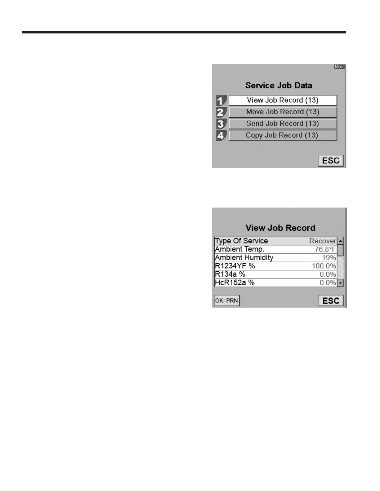
Figure 7
Screen shows the Service Job Data options.
1. Press MENU on the machine’s control panel.
2. Select A/C SERVICE FUNCTION.
3. Select SERVICE JOB DATA.
4. Refer to Figure 7. The choices are:
• VIEW JOB RECORD — a list of VINs is displayed.
Use the UP or DOWN arrow to highlight the VIN for
which to print service data.
• MOVE JOB RECORD — follow the prompts for this
option to transfer all records to an SD card. The most
recent 100 records will also be retained in Service
Job Data.
• SEND JOB RECORD — follow the prompts for this
option to transfer all records to a server. The most
recent 100 records will also be retained in Service
Job Data.
• COPY JOB RECORD — follow the prompts for this
option to select the service job to copy to the SD
memory card.
Note: Job records must be transferred to a PC for permanent
storage. The SD card will be erased if left in the A/C machine
during a web update.
Figure 8
Screen shows some of the information
available under View Job Record.
26
Page 29
Procedure to Move Job Records
1. Lift the rubber ap on the upper right hand side of the
machine, and install an unlocked SD card into the SD
card slot.
2. Select MOVE JOB RECORD from the A/C Service
Function Menu.
3. After the les have been successfully moved to the
SD card, the machine displays
FILE TRANSFERRED
PRESS OK TO CONTINUE
A/C Service Function
4. Press OK and remove the SD card.
5. Upload the les from the SD card to a personal
computer for storage.
Note: Job records should be transferred to a PC for
permanent storage. An SD card will be erased if left
in the A/C machine and a web update is performed.
6. The MOVE JOB RECORD and SEND JOB RECORD
screens will now show there are no les available
to move.
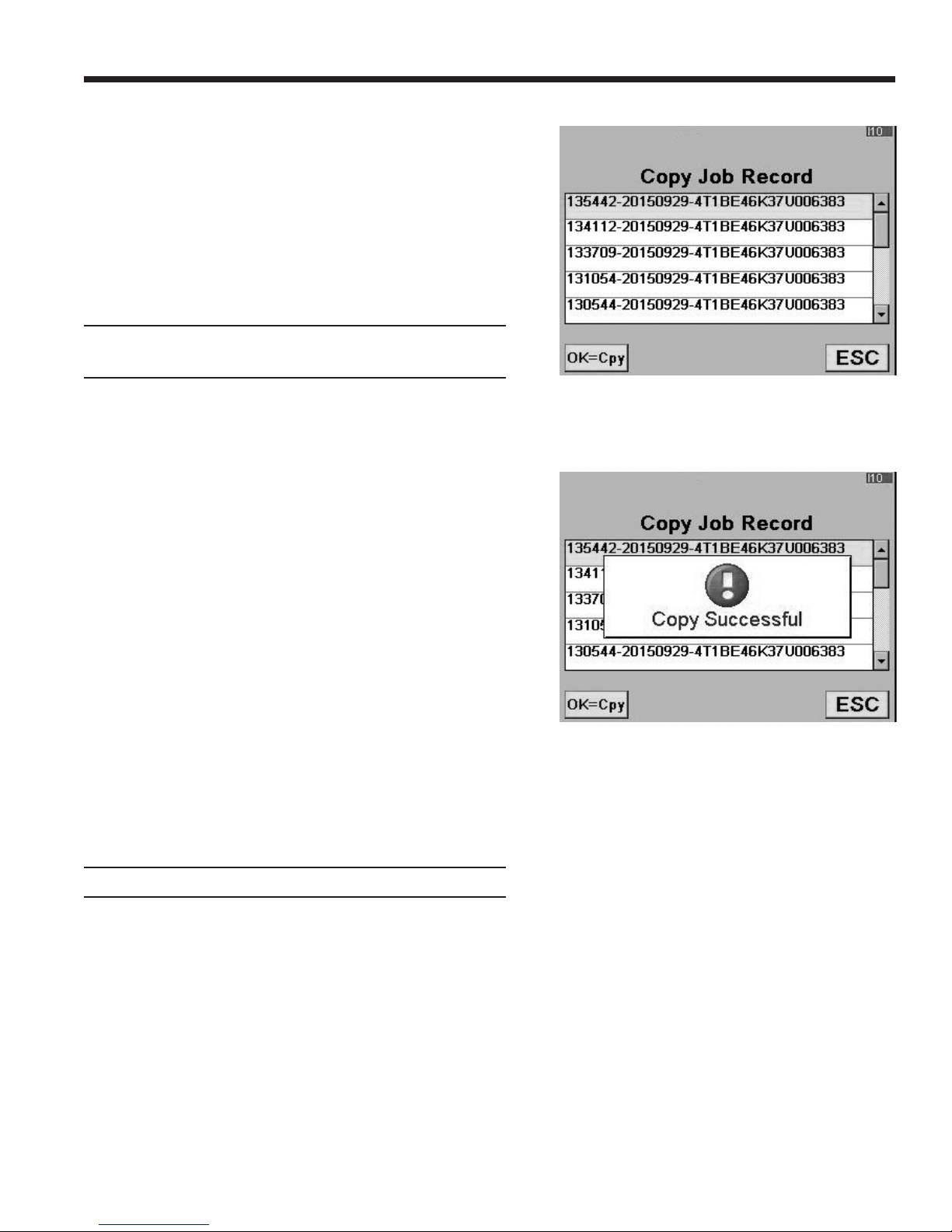
Procedure to Copy Job Record
1. Lift the rubber ap on the upper right hand side of the
machine, and install an unlocked SD card into the SD
card slot.
2. Select COPY JOB RECORD from the A/C Service
Function Menu.
3. Select the job record to copy and press OK. See
Figure 9.
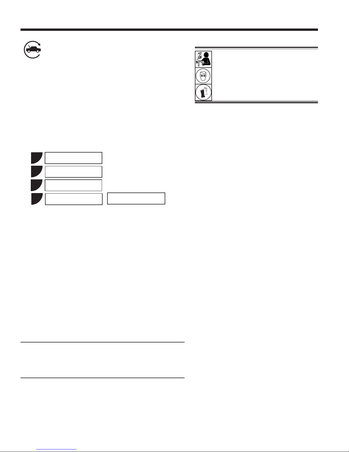
4. After the le has been successfully copied to the SD
card, the machine displays
Figure 9
Screen shows job records available to copy.
Figure 10
Screen shows job record was copied to SD card.
COPY SUCCESSFUL
See Figure 10. Press OK and remove the SD card.
5. Upload the les from the SD card to a personal
computer for storage.
Note: Job records should be transferred to a PC for
permanent storage. An SD card will be erased if left
in the A/C machine and a web update is performed.
581371 REV A
27
Page 30
A/C Service Function
Automatic
The automatic function allows a user to program an automatic
recovery, vacuum, leak test, and/or charge sequence. A total
automatic sequence can take up to an hour.
1. Connect service hoses to the vehicle’s service ports and
open the couplers.
2. Select AUTOMATIC.
3. Perform the VIN entry function. If a matching database
entry is found, the recommended charge amount will be
populated automatically.
4. The machine displays
1
2
3
HP
LP
HP + LP
WARNING: To prevent personal
injury while working with refrigerant,
read and follow the instructions
and warnings in this manual, and
wear protective equipment such as
goggles and gloves.
Note: If problems are encountered during the
automatic sequence, the machine will “beep”
three times, the red lights on the front of the
machine will blink, and the control panel
readout will pinpoint the problem encountered.
The sequence remains paused until the user
enters a decision regarding how to proceed.
5
Use the number keys on the keypad to make selections 1–3
for the vehicle A/C system.
For selection 5, accept the default value or enter a value
and press OK.
Note: If the default value is 0.000 kg, a value must be
entered to continue.
5. Select a vacuum time:
• Press OK to accept the default evacuation time, or
• The machine pulls a vacuum on the A/C system for
6. The machine displays
Refrigerant
enter the desired vacuum time using the number keys,
and press OK.
the programmed amount of time. During the vacuum
process, the machine will perform an air purge if
needed.
0.000 kg
HAS THIS MACHINE BEEN USED TO SERVICE A
SYSTEM UTILIZING PAG OIL?
IF YES, SELECT OK TO PERFORM A HOSE FLUSH
OR IF NO, ESC TO CONTINUE CHARGE.
• If OK is selected, the machine prompts for a Hose
Flush procedure. Connect high-side (red) and low-side
(blue) service hoses to the storage ports, and open
the coupler valves. Press OK. Move the service hoses
to the vehicle’s service ports and open the couplers.
Press OK.
28
Page 31

• If ESC is selected, the machine continues on to
RECOVERY (or VACUUM if there is no pressure for
a recovery).
7. If pressure is detected
• The machine checks the refrigerant in the vehicle
to verify it is R-1234yf and not contaminated, which
is required by SAE J2843. If the purity reading is
acceptable, the machine will give the option to run
diagnostic pressures before recovery.
• Press OK to run diagnostic pressures; press ESC to
continue with RECOVERY.
• If OK was selected, follow prompts to start the vehicle
and set the A/C system according to service manual
A/C performance test requirements. Press OK after
pressure stabilizes. Press OK again to print data;
press ESC to continue with RECOVERY.
8. The machine performs the VACUUM process as previously
selected in Step 5.
A/C Service Function
Service
Hoses
Connected
to Storage
Ports
Figure 11
9. The machine performs the CHARGE process:
• 10–20 minute vacuum leak test (applies vacuum,
checks for vacuum decay.
• Pre-charge leak test (charges 15% of overall charge,
prompts user to perform manual leak test using a leak
detector certied to SAE J2913.)
• Charges the A/C system.
10. After the machine charges the system, the machine again
gives the option to run a Diagnostic Pressures test.
• Press OK to run diagnostic pressures; press ESC to
continue.
11. Follow prompts to equalize liquid refrigerant into the vehicle
A/C system for maximum charge accuracy.
12. When the sequence is complete, close the high-side (red)
and low-side (blue) coupler valves.
13. When prompted, remove service hoses from the A/C
system and install them on the machine’s storage ports.
Select OK to begin clearing hoses. This prepares the
machine for the next service.
CAUTION: If the low-side (blue) or high-side
(red) coupler valve is left open during the
hose clearing process, the system will pull
refrigerant back out of the vehicle.
14. The machine displays a summary of actions performed
during the automatic sequence.
581371 REV A
29
Page 32

A/C Service Function
Recovery
1. Empty the oil drain bottle before starting a recovery.
Remove the oil drain bottle from the machine by pulling
the bottle straight down — do not use a twisting or rocking
motion. Refer to Figure 12.
2. Connect the high-side (red) and low-side (blue) hoses to
the vehicle A/C system.
3. Open the coupler valves on the hoses by turning the
collars clockwise.
4. Select the recovery function by pressing the RECOVER button
on the control panel, or by selecting Recovery from the A/C
Service Function menu.
5. Perform the VIN entry function.
6. The machine checks the refrigerant in the vehicle to verify
it is R-1234yf and not contaminated. If the refrigerant
purity is acceptable, the machine begins the recovery
process. A clicking noise indicates a solenoid is opening
and closing — this is normal.
WARNING: To prevent personal
injury while working with refrigerant,
read and follow the instructions
and warnings in this manual, and
wear protective equipment such as
goggles and gloves.
7. The machine displays
RUN DIAGNOSTIC PRESSURES?
To store and/or print diagnostic pressures at this point,
follow the prompts to start the vehicle and set the A/C
system according to service manual A/C performance
test requirements. Press OK.
The machine displays when to capture the values and
when they may be printed.
8. The machine runs a self-clearing cycle to clear refrigerant
from its internal plumbing.
9. When the system has recovered to 0 psi, the vacuum pump
starts and runs until recovery is complete.
10. After oil drain is complete, the machine displays a summary
of gas recovered. At this point you may print out recovery
information and pre-recovery diagnostics by selecting OK.
The displayed recovered weight can vary depending on
ambient conditions and should not be used as an indicator
of scale accuracy.
11. The amount of oil that was removed from the A/C system is the
amount of new oil that should be charged into the A/C system
after evacuation is complete.
Oil Drain
Bottle
Figure 12
• Use only new oil to replace the oil removed during
the recycling process.
• Dispose of used oil according to government regulations.
Recovery is complete.
30
Page 33

A/C Service Function
Vacuum
1. Connect service hoses to the vehicle’s service ports.
2. Open the coupler valves by turning the collars clockwise.
3. Press VACUUM.
4. Perform the VIN entry function.
5. Press OK to accept the default evacuation time, or enter
the desired vacuum time using the number keys, and
press OK.
• The machine pulls a vacuum on the A/C system for
the programmed amount of time. During the vacuum
process, the machine will perform an air purge if
needed.
• The machine stops when the specied amount of
time has elapsed. At this point vacuum information
can be printed by selecting OK. Press ESC to return
to the main menu.
IMPORTANT: The unit pulls a deep vacuum
on the vehicle A/C system to remove air
and boil off moisture that might be present
in the system.
Achievement of a sufcient deep vacuum
depends greatly on vacuum pump oil
condition. Change vacuum pump oil after 10
hours of pump operation; change vacuum
pump oil more frequently if the equipment is
used on A/C systems that have been open
for extended periods of time.
Note: When the vacuum pump has operated for
10 hours, the machine prompts for an oil change.
Select OK to proceed with an oil change; select
ESC
to continue with the vacuum process. Refer
to “Maintain Vacuum Pump Oil” on page 36.
581371 REV A
31
Page 34

A/C Service Function
Charge
The following tests are automatic and performed as required
by SAE J2843:
• vacuum that runs 5–20 minutes to achieve the correct
level
• 5-minute vacuum rise test
• 15% charge
• manual leak test using a leak detector certied to SAE
J2913
Notes:
• J2843 leak testing is intended to nd a gross leak before
charge, for safety reasons. It is not intended to take the
place of other established leak test practices.
• To avoid false failures, the temperatures of the vehicle
system and the recovery machine should be within ±5°C.
WARNING: To prevent personal
injury while working with refrigerant,
read and follow the instructions
and warnings in this manual, and
wear protective equipment such as
goggles and gloves.
Refer to the vehicle service manual for specic vehicle
instructions.
1. Connect service hoses to the vehicle’s service ports and
open the couplers.
2. Press CHARGE.
3. Perform the VIN entry function. If a matching database
entry is found, the recommended charge amount will be
populated automatically.
4. The machine displays
1
2
3
7
Use the number keys on the keypad to select a HP, LP,
or HP / LP charge mode for the vehicle A/C system.
For selection 7, accept the default or enter a value and
press OK twice.
HP
LP
HP + LP
Refrigerant
0.000 kg
Note: If the default value is 0.000 kg, a value must be
entered to continue.
32
Page 35

5. The machine displays
HAS THIS MACHINE BEEN USED
TO SERVICE A SYSTEM UTILIZING
PAG OIL?
IF YES, SELECT OK TO PERFORM A HOSE FLUSH
OR IF NO, ESC TO CONTINUE CHARGE.
If OK is selected, the machine prompts for a Hose Flush
procedure. Connect high-side (red) and low-side (blue)
service hoses to the storage ports, and open the coupler
valves. Press OK. If ESC is selected, the machine
continues with CHARGE.
6. Move the service hoses to the vehicle’s service ports and
open the couplers. Press OK. The machine performs
automatic tests on the system as required by SAE J2843.
7. When prompted, perform a manual leak test using a leak
detector certied to SAE J2913. Once the leak test has
been completed, CHARGE continues.
A/C Service Function
Note: The charge process includes an
automatic vacuum leak test, after which the
system is pressurized with a small amount of
refrigerant for a manual leak test.
Moving or bumping the machine at this point can result in
an inaccurate charge. When the charge cycle gets close
to the desired weight value, the machine slows down. It
will charge, settle, charge again, settle, etc.
8. At the end of CHARGE, the machine prompts through a
Diagnostic Pressures test. This process is required to
provide vehicle system pressures for the stored and
printed warranty service data.
9. Follow prompts to equalize liquid refrigerant into the vehicle
A/C system for maximum charge accuracy.
10. When prompted, close the coupler valves and remove
the service hoses from the A/C system. Install the hoses
on machine’s storage ports.
11. Press OK to begin clearing hoses to prepare the machine
for the next service.
12. When the hoses are clear, the display shows a summary
of charge results, which can be printed by pressing OK.
Note: Complete service results can be printed at the end of
the vehicle’s entire service by selecting the vehicle VIN from
the SERVICE JOB DATA menu.
CAUTION: If the low-side (blue) or high-side
(red) coupler valve is left open during the
hose clearing process, the system will pull
refrigerant back out of the vehicle.
The SERVICE JOB DATA menu is found by pressing MENU
and choosing A/C SERVICE FUNCTIONS.
The vehicle A/C system is now ready for use.
581371 REV A
33
Page 36

A/C Service Function
Hose Flush
Selecting this menu item will cause the machine to ush its
internal plumbing.
1. When prompted, connect the service hoses from the
machine to their storage ports and open coupler valves
as shown in Figure 13.
2. Check the vacuum pump oil level sight glass and verify
the oil level is correct.
3. Open the service couplers by turning the couplers clockwise.
4. The machine performs an internal clearing of its plumbing,
and sounds an alarm when complete. Press OK to exit.
WARNING: To prevent personal
injury,
Only qualied personnel may
•
perform inspections and
repairs to this machine.
Read and follow the
•
instructions and warnings
in this manual, and wear
protective equipment such as
goggles and gloves.
Do not operate the machine
•
when the shroud has been
removed.
Figure 13
Service
Hoses
Connected
to Storage
Ports
34
Page 37

Tank Filling
This menu item is used to transfer refrigerant from a source
tank to the ISV. This procedure works only if the ISV contains
less than the maximum amount of refrigerant programmed
under Tank Fill Adjustment.
Note: If a source tank is connected to the tank ll hose while
the machine is sitting idle, the machine automatically adds
refrigerant up to the level set during Tank Fill Adjustment.
1. Connect an R-1234yf source tank to the tank ll hose at
the rear of the machine. See Figure 14.
Note: The tank ll hose and the tank access port have
left-hand threads.
2. Hand tighten the tank ll hose.
3. Open the tank valve.
4. Mount the source tank on the shelf at the rear of the
machine, oriented to supply liquid refrigerant to the
connection. Tighten the holding strap around the source
tank. Verify the tank does not restrict air ow from the vent.
Unit Maintenance
WARNING: To prevent personal
injury while working with refrigerant,
read and follow the instructions
and warnings in this manual, and
wear protective equipment such as
goggles and gloves.
5. Select TANK FILLING from the Unit Maintenance menu.
The machine displays
FILL AMOUNT
XX.XXX
CONNECT SOURCE TANK TO FILL HOSE
6. Press OK. The machine checks the refrigerant in the
source tank to verify it is R-1234yf and not contaminated.
The machine displays the following screens:
WARM UP
CALIBRATION IN PROGRESS
GAS IDENTIFY
REFRIGERANT PURITY ACCEPTABLE
and after ve seconds begins lling the internal storage
vessel (ISV).
7. The machine automatically stops when the preset tank
ll level is reached. To stop the tank ll before the preset
level is reached, select ESC.
8. If using a non-rellable tank, the machine must display
SOURCE TANK EMPTY
Strap
Tank Fill
Hose
Figure 14
Note: After the tank ll process is complete,
the display will not show the same amount as
the programmed ll level.
The display shows the amount of refrigerant
that is available for charging, which is
approximately 0.91 kg less than the total
amount of refrigerant in the tank.
before the tank can be discarded.
581371 REV A
35
Page 38
Unit Maintenance
Maintain Vacuum Pump Oil
1. Select MAINTAIN VACUUM PUMP OIL from the Unit
Maintenance menu or when prompted. The display
shows how long the vacuum pump has operated since
the last oil change.
X HOURS X MINUTES
CHANGE OIL?
2. Press OK. The machine will display
WARMING OIL FOR BETTER DRAINING
PLEASE WAIT
X:XX
The vacuum pump will run 30 seconds to warm the
oil. The display shows
OIL CHANGE
UNIT CLEARING
WAIT
while the compressor runs to eliminate any pressure
in the vacuum pump.
3. After the compressor stops, slowly open the oil ll
cap to verify there is no pressure in the machine. Then
carefully remove the cap. See Figure 15.
CAUTION: To prevent personal injury,
do NOT operate the machine at any other
time without the oil ll port cap installed,
because the vacuum pump is pressurized
during normal operation.
Oil Fill Cap
and Port
Sight
Glass
Oil Drain
Fitting
4. The display shows
DRAIN THE OLD OIL
ADD 150 ML OF NEW OIL
PRESS OK TO CONFIRM
PRESS ESC TO EXIT
Remove the oil drain tting cap, and drain the oil into
a suitable container for disposal. Replace the cap and
close tightly.
5. S
lowly add approximately
to the pump through the oil ll port. Press OK to start
the vacuum pump.
6. The display shows
150 ml of vacuum pump
FILL PUMP TO CENTER OF SIGHT GLASS
PRESS OK WHEN COMPLETE
S
lowly add
port until the oil level rises to the center of the sight glass.
7. Install the cap on the oil ll port and close tightly
OK to return to the Unit Maintenance menu.
vacuum pump
oil to the pump through the oil ll
Figure 15
oil
Caution: It is the responsibility of the user to
monitor vacuum pump oil level and clarity.
If contaminated oil is not removed from the
vacuum pump and replaced, the vacuum
pump will be permanently damaged.
. Press
36
Page 39

Unit Maintenance
Maintain Filter
The lter is designed to trap acid and particulates and to
remove moisture from refrigerant. To meet the mandate for
adequate moisture and contaminant removal, the lter must be
replaced after 150 kg (331 lb.) of refrigerant has been ltered.
The machine gives a warning when 100 kg (220 lb.) of the
lter capacity has been used; the machine locks down when
the 150 kg (331 lb.) lter capacity has been reached and will
no longer function.
WARNING: Components in the machine are under
high pressure. To prevent personal injury, change
lter only when the machine prompts.
Check Remaining Filter Capacity
1. Select MAINTAIN FILTER from the Unit Maintenance
menu or when the machine prompts. The machine displays
the amount of lter capacity remaining until the machine
locks down.
2. When prompted, select OK to change the lter; select
ESC to resume using the machine.
the
WARNING: To prevent personal
injury while working with refrigerant,
read and follow the instructions
and warnings in this manual, and
wear protective equipment such as
goggles and gloves.
Caution: To prevent equipment damage,
use only authentic Robinair No. 34724
lters in this machine. All performance
tests and claims are based on using this
specic lter.
Replace the Filter and Sample Hose Assembly
1. If OK was selected to change the lter, the machine clears
the lter, then prompts for the new lter code to be entered.
Use the keypad to enter the serial number that appears
on the new lter and select OK. If
SERIAL NUMBER IS NOT VALID
is displayed, the serial number has been incorrectly
entered, or the lter has already been used in this machine.
2. The machine displays
TURN UNIT OFF
REMOVE SHROUD AND REPLACE FILTER,
IDENTIFIER FILTER, AND
IDENTIFIER SAMPLE HOSE ASSEMBLY
Shut off the machine. Remove the oil bottle. Remove the
four screws holding the shroud. See Figure 16.
Remove the four screws
holding the shroud.
581371 REV A
Figure 16
37
Page 40

Unit Maintenance
3. Hang the shroud on the back of the machine as shown
in Figure 17.
4. Remove the lter by turning it counterclockwise (as viewed
from the bottom of the lter).
5. Look at the new lter—verify both o-rings are lubricated
and correctly located in the grooves as shown in Figure 18.
6. Install the new lter by threading it clockwise into place.
Verify the lter is positioned correctly as shown in Figure
19. Tighten the lter to 20 N•m.
Figure 17
Filter
O-rings
H
E
L
9
P ME
O
K
N
U
S
T
OP
E
S
C
Hang
Shroud
Here
Assembled
Correctly
Figure 19
Figure 18
Assembled
Incorrectly
38
Page 41

Refrigerant Identier
Unit Maintenance
The refrigerant identier samples refrigerant going into the
ISV to verify it is R-1234yf and not contaminated. Replace the
sample hose assembly during every lter change and also if
prompted by an error message saying the hose is clogged.
See Figure 20.
1. Disconnect the existing sample hose assembly between
the solenoid and the refrigerant identier, and install a
new sample hose assembly.
Note: If the lter is any color but white, the lter needs to
be replaced also.
2. Pull the lter out of the brackets while removing the barbs
from the rubber connectors.
3. Install a new lter with the arrow pointing upward as
shown. Push the lter barbs into the rubber connectors.
4. Install the shroud on the machine and switch the power ON.
Calibration Check
This function is used to ensure the machine’s internal scale
is always calibrated. During this test, use only the calibration
weight that is provided with the machine.
Barb
Refrigerant Identier
Sample Hose
Assembly
Install new lter with
arrow ↑ positioned as
shown.
Figure 20
Replace the sample hose assembly during
every lter change.
1. Select CALIBRATION CHECK in the Unit Maintenance
menu. The machine displays
ATTACH WEIGHT TO BOTTOM OF MACHINE
PRESS OK TO CONFIRM PRESS ESC TO QUIT
2. Refer to Figure 21, and verify the magnet on the bottom
of the machine is clean.
3. Attach the calibration weight to the magnet on the bottom
of the machine. Select OK.
• If the display shows
PROCEDURE COMPLETED
the scale is in calibration. Select OK.
• If the display shows
CALIBRATION REJECTED
the scale is out of calibration. Contact an authorized
Robinair service center for assistance.
4. Remove the calibration weight from the scale.
Magnet
Figure 21
581371 REV A
39
Page 42

Unit Maintenance
Refrigerant Management
This Unit Maintenance menu item displays the amount of
refrigerant recovered, charged, and replenished (for the life
of the machine), and ltered since the last lter change.
Air Purge Info
This Unit Maintenance menu item displays the internal storage
vessel (ISV) pressure and temperature. Use this information
to check the ISV for excessive pressure.
Backlight
Select this Unit Maintenance menu item and use the left and
right arrow keys to adjust the contrast on the display screen.
Replace Service Hoses and/or
Service Couplers
Ensure pressure has been removed from service hoses before
disconnecting a hose or coupler from the machine. Pressure
gauges must read at or below 0 psig.
If pressure exists, recover the refrigerant from the hoses
before disconnecting a hose or coupler.
1. The machine performs a 30 second vacuum to ensure
hoses are empty.
2. The machine displays
DISCONNECT OLD HOSES AND
REPLACE WITH NEW HOSES
PRESS OK TO CONTINUE
PRESS ESC TO EXIT
Remove and replace old service hoses. Press OK.
3. The unit directs the user to connect hoses to the storage
ports and press OK to begin unit conditioning.
4. A vacuum is performed on the unit until the vacuum level
reaches 525 micron.
5. The machine is now ready to use.
40
Page 43

General Maintenance
Wipe off the machine often using a clean cloth to remove
grease and dirt.
Periodically check hoses and connections for leakage. Use
a J2913 electronic leak detector to check ttings when the
unit has been disconnected from its power source and the
shroud has been removed. If a leak is detected and cannot
be repaired, contact a Robinair authorized service center.
Unit Maintenance
581371 REV A
41
Page 44

Maintenance Procedures
Replace the Oxygen Sensor in the
Refrigerant Identier
The refrigerant identier in the machine contains a replaceable
oxygen sensor that can affect the way the machine works if
the sensor is not functioning correctly.
• If the machine displays the following message, immediately
replace the oxygen sensor:
OPERATING TIME OF THE IDENTIFIER AND UNIT
ARE LIMITED
REPLACE ID O2 SENSOR SOON
UNIT WILL BECOME NONFUNCTIONAL
• If the machine displays the following message, the oxygen
sensor has expired. Neither the identier nor the machine
is able to recover or add refrigerant to the internal tank.
ANALYZER ERROR 6
O2 SENSOR FAILURE
SENSOR MUST BE REPLACED
UNIT WILL NOT RECOVER OR ALLOW TANK FILL
SEE MANUAL
1. Disconnect the machine from its power source.
Remove four screws
holding shroud.
2. Remove the oil bottle, and remove the four screws holding
the shroud. See Figure 22. Hang the shroud on the back
of the machine.
3. Disconnect the wire harness, USB connector, and sample
hose from the identier. See Figure 23.
4. Remove the two screws holding the identier to the
machine, and remove the identier.
5. Carefully pry the oxygen sensor cap from the housing.
Gently pull on the cap and wires until the connector exits
the housing.
CAUTION: The wire connected to the cap is connected
internally to the identier. To prevent equipment damage,
do NOT pull on this wire.
Figure 22
Disconnect wire harness,
USB connector,
and sample hose.
Oxygen
Sensor
Cap
Figure 23
42
Page 45

Maintenance Procedures
6. Disconnect the wire harness at the connector by pressing
on the center tab. Pull the connectors apart. See Figure 24.
7. Move the cap and harness aside. Hold the lead from the
sensor, and use a at-blade screwdriver to unthread and
remove the oxygen sensor. See Figure 25.
8. Remove the pink protective lm from the threaded end
of the new oxygen sensor.
9. Install the new oxygen sensor, using the screwdriver to
thread it into place. Tighten the sensor to 4 in. lb.
10. Reconnect the lead at the connector, and tuck the wires
into the opening.
11. Replace the cap and push until it “clicks” into place. Install
the identier onto the machine, and reconnect the wire
harness, USB connector, and sample hose.
12. Verify the wiring is not binding, and replace the shroud.
Press to
disconnect
wire harness.
Figure 24
Use at-blade
screwdriver to
remove sensor.
581371 REV A
Figure 25
43
Page 46

Maintenance Procedures
Tank Fill Hose Filter Service
The tank ll hose at the rear of the machine (see Figure 26)
contains a lter that can be cleaned when it appears that
refrigerant ow is restricted.
When the machine senses low ow, it can display one of the
following messages:
• SOURCE TANK EMPTY, but the source tank is known
to contain refrigerant, connections are secure, and the
source tank valve is open.
• REPLACE IDENTIFIER FILTER, but the refrigerant
identier lter is known to be unrestricted, the source
tank contains refrigerant, connections are secure, and
the source tank valve is open.
The tank ll hose lter might be plugged.
Cleaning the Tank Fill Hose Filter
1. First ensure that pressure does not exist in the
line. Disconnect the external source tank, and perform
a manual tank ll to capture any refrigerant in the line.
2. Disassemble the tank ll hose at the lter housing as
shown in Figure 27.
3. Remove the lter. The recommended method to remove
debris from the lter is by using air pressure.
Note: If a solvent is used, allow adequate drying time
before reassembly.
4. After the lter has been installed back into the lter housing,
torque the housing assembly to 8.5 N•m (6 ft. lb.).
Tank Fill
Hose
Figure 26
Disassemble the
Filter Housing
Figure 27
44
Page 47
Maintenance Procedures
Edit Print Header
To make changes to the text that appears in the header on
each printout:
1. Select DEALER INFO from the Unit Setup menu.
2. Use the arrow key to move to the eld that needs to
be changed.
3. Press the Menu key to display a virtual keyboard.
4. Use the arrow keys to move around the keyboard. Press
OK to enter a character.
5. Press the Menu key to exit the keyboard and move to
the next ll eld.
6. Press OK to save the data and press ESC to exit
the keyboard.
Dealer Code
Garage
Address
City
Tel
Fax
E-mail
7. This procedure is explained in more detail in “Dealer Info”
on page 12.
Replace Printer Paper
To install a new paper roll in the printer:
1. Remove the cover on the printer by pulling out on the tab
as shown in Figure 29.
2. Remove the paper core.
3. Install the new roll of paper with the end of the paper at
the top of the roll.
4. Assemble the cover onto the printer with the leading edge
of the paper over the roller.
Figure 28
Leading Edge of
Paper Over Roller
Tab
Figure 29
581371 REV A
45
Page 48

Replacement Parts and Glossary
Replacement Parts
Component Replacement Part No.
Calibration Weight 16214
Contaminated Refrigerant Tank (optional) 17990
Filter 34724
Filter Maintenance Kit 13172
(includes lter and vacuum pump oil)
Identier Filter 16913
Identier Oxygen Sensor 16916
Identier Sample Hose Assembly 16106
Oil Drain Bottle 19100
PAG Oil Injector 18465
POE Oil Injector 18470
Printer Paper (3 rolls) 34214
Service Coupler, High-Side (red) 18123
Service Coupler, Low-Side (blue) 18122
Service Coupler Set 18124
(high-side [red] and low-side [blue)] couplers)
Service Hose (low-side, blue) 70123
Service Hose (high-side, red) 70124
Service Hose Set 71234
(high-side [red] and low-side [blue)] hoses)
Tank Fill Hose Filter 10233
Vacuum Pump Oil (quart) 13203
Vacuum Pump Oil (gallon) 13204
Vinyl Dust Cover (optional) 17499
CAUTION: To prevent
personal injury, use only those
repair parts called out in this
parts list. Items found in this
parts list have been carefully
tested and selected by Robinair.
Contact Robinair Customer
Service (1-800-533-6127) for
more information regarding the
replacement parts listed here.
Glossary
A/C System : The vehicle air conditioning system being serviced.
Evacuation : Moisture and other non-condensables are removed from an A/C system by a vacuum pump
capable of pulling the system to 0.5 mbar absolute.
Internal Storage Vessel (ISV) : The rellable refrigerant storage tank designed specically for this machine;
9.50 kg (20.94 lb.) capacity.
Leak Test (Vacuum) : Components containing refrigerant are evacuated and monitored for pressure rise,
which could indicate a leak.
Machine : Model No. J-52405
PAG : Polyalkylene Glycol
POE : Polyolester Oil
Recovery / Recycling : Refrigerant is recovered from an A/C system, ltered, and stored in the ISV.
Refrigerant : R-1234yf
VCI : Vehicle Communication Interface
46
Page 49

Troubleshooting Messages
Display Cause Solution
AIR CALIBRATION LOW
AIR FLOW ERROR
CHARGE IN PROGRESS
AIR PURGE
HIGH OUTPUT
IDENTIFIER FILTER AND
SAMPLE TUBE MAY
NEED REPLACEMENT
IDENTIFIER OUT OF
TEMPERATURE RANGE
Possible refrigerant in external
calibration air.
Fan is not working. Air ow is
blocked.
Non-condensable gas is present
in ISV that could contaminate A/C
system.
Possible electromagnetic or RF
(radio frequency) interference.
1. Insufcient refrigerant ow to
identier.
2. Sample hose or lter inside
refrigerant identier is plugged
or contaminated with oil.
Identifier temperature outside
operating range.
Check air ventilation and air ow.
Exit current test. Contact Robinair authorized
service center.
Before it charges, the machine purges air
out of the ISV.
Move unit away from EMF or RFI sources.
1. Check source tank for pressure and
secure valve connections.
2. Refer to “Maintain Filter” on page 37
change identier lter and sample hose.
Check unit ventilation and ambient
conditions.
to
INSUFFICIENT
PRESSURE
INSUFFICIENT
REFRIGERANT
ISV CONDITION
OIL OUT OF LIMIT
PRESSURE TOO HIGH
If pressure is less than 0.7 bar,
refrigerant cannot be identied.
After selecting CHARGE and
entering a desired weight, if the
weight entered will leave less than
.91 kg (2 lb.) of refrigerant in ISV
after charge, charge function will
not start.
Machine is circulating refrigerant
to build ISV pressure for a charge
cycle.
Vacuum pump has run for 10
hours; vacuum pump oil should
be replaced.
Excessive pressure has been
detected.
Refer to “ Vacuum” on page
31 and follow instructions to evacuate
system.
Refer to “Tank Filling” on page 35.
Charge process is automatically interrupted
and machine operates in a mode to build
tank pressure. Once tank pressure
is sufficient, machine automatically
completes charge.
Refer to “Maintain Vacuum Pump Oil” on
page 36 for instructions.
Press ESC. Refer to “Recovery” on page 30
and recover refrigerant before proceeding.
581371 REV A
47
Page 50

Troubleshooting Messages
Display Cause Solution
PURITY TEST FAILED
Refrigerant in vehicle is either not
R-1234yf or it is contaminated.
Refer to “Setup, Tank Fill, and
Background Tank Fill Functions”
on page 49. Use 25700 external
recovery machine to recover refrigerant.
PURITY TEST FAILED
XX% AIR
SOURCE TANK EMPTY
SYSTEM PRESSURE TOO
LOW TO CONTINUE
UNSTABLE OUTPUT
VACUUM DECAY TEST
FAILED
1. Insufcient refrigerant ow to
identier.
2. Excessive air in source tank.
1. Machine senses low pressure.
2. Filter in tank ll hose is plugged.
If pressure is less than 0.7 bar, the
refrigerant cannot be identied.
1. Insufcient refrigerant ow to
identier.
2. Possible electromagnetic or RF
(radio frequency) interference.
A leak in the vehicle A/C system.
1. Check source tank for pressure and
secure valve connections.
2. Replace source tank with good
refrigerant.
1. Check the source tank for pressure and
secure valve connections.
2. Refer to “Tank Fill Hose Filter Service”
on page 44.
If vehicle is very cold, allow vehicle to warm
up and retest. Otherwise enter Vacuum
mode and evacuate system.
1. Check source tank for pressure and
secure valve connections.
2. Move unit away from EMF or RFI
sources.
Exit current test and perform repairs on
the vehicle A/C system.
48
Page 51

Troubleshooting Procedures
Setup, Tank Fill, and Background Tank Fill Functions
Display Message: Purity Test Failed
During SETUP, TANK FILL, or BACKGROUND TANK FILL,
if the machine displays
PURITY TEST FAILED
RECOVER CONTAMINATED
REFRIGERANT FROM SYSTEM
AND HOSES.
OK TO RETRY ESC TO QUIT
the refrigerant in the source tank is either not R-1234yf or it
is contaminated. In either case, it should not be added to the
internal storage vessel (ISV) in the machine. The contaminated
refrigerant sampled by the refrigerant identier in the machine
must be removed.
A refrigerant recovery machine (No. 25700)
dedicated to contaminated refrigerant is
required for the following steps. Refer to
Figure 30.
1. Connect the tank ll hose adapter (provided
in the Accessory Kit) to the low-side coupler
of the 25700 refrigerant recovery machine.
2. Connect the other end of the adapter to
the tank ll hose tting on the machine.
3. Connect the discharge hose from the
25700 to a tank specied to receive
contaminated refrigerant.
4. Start the 25700 and open the coupler
valve. Run a recovery until the gauge on
the 25700 indicates vacuum.
5. Shut off the 25700.
6. Slowly and carefully disconnect the adapter
from the tank ll hose and the 25700. There
might still be a small amount of pressure
in the line.
Tank Fill Hose
Adapter
581371 REV A
Refrigerant Recovery Machine
No. 17990
Contaminated
Refrigerant Tank
Figure 30
49
Page 52

Troubleshooting Procedures
Recovery Function or Automatic Function
Display Message: Purity Test Failed
During the RECOVERY function or AUTOMATIC RECOVERY
function, if the machine displays
PURITY TEST FAILED
RECOVER CONTAMINATED
REFRIGERANT FROM SYSTEM
AND HOSES.
OK TO RETRY ESC TO QUIT
the refrigerant in the source tank or in the vehicle A/C system
is either contaminated or it is not R-1234yf. In either case,
it should not be added to the internal storage vessel in the
machine.
Connect No. 25700
contaminated refrigerant
recovery machine here.
The contaminated refrigerant sampled by the refrigerant
identier in the machine must be removed.
A refrigerant recovery machine (No. 25700) dedicated to
contaminated refrigerant is required for the following steps:
1. With the machine still connected to the vehicle and the
couplers open, connect the low-side (blue) coupler from
the 25700 to the contaminant recovery port on the back
of the machine. See Figure 31. Open the coupler valves.
2. Connect the discharge hose from the 25700 to a tank
designed to receive contaminated refrigerant.
3. Start the 25700 and run a recovery according to instructions
supplied with the machine.
4. Upon achieving a vacuum in the vehicle (or per recovery
machine instructions), disconnect the 25700 from the
machine.
5. Clear the vehicle of residual contamination according to the
vehicle manufacturer’s instructions before continuing service.
Figure 31
50
Page 53

Troubleshooting Procedures
Recovery Function
Display Message: System Pressure
If system pressure is below 0 bar gauge, until pressure
increases, the display reads
SYSTEM PRESSURE
PRESS OK TO RETRY
PRESS ESC TO EXIT
Verify high-side (red) and low-side (blue) hoses are connected
and coupler valves open. Press OK to try again, or press ESC
to exit and perform a vacuum.
Display Message: Filter Weight XXX LB
If 100 kg (220 lb.) or more of refrigerant has been recovered
since last lter change, display reads
FILTER WEIGHT XXX LB
To meet requirements, it is mandatory to replace the lter
after 150 kg (331 lb.) of refrigerant has been ltered. The
machine gives a warning to replace the lter when lter weight
reaches 100 kg (220 lb.); when lter weight reaches 150 kg
(331 lb.), the machine locks out and ceases to operate. Refer
to “Maintain Filter” on page 37.
Display Message: Identier Filter and Sample
Tube May Need Replacement
If the machine displays
IDENTIFIER FILTER AND SAMPLE TUBE MAY
NEED REPLACEMENT
the lter inside the refrigerant identier needs to be replaced.
Press OK to conrm, and refer to “Maintain Filter” on page 37.
581371 REV A
51
Page 54

Troubleshooting Procedures
Vacuum Function
Display Message: Pressure Too High
Before the machine begins evacuating the A/C system, it
checks for pressure in the system that might damage the
vacuum pump. If pressure greater than 0.7 bar is detected,
the machine displays
PRESSURE TOO HIGH
CHECK CONNECTIONS
Select OK, and recover refrigerant before proceeding.
To ensure an accurate leak test, it is imperative that a thorough
recovery and evacuation of the system be performed. During
the recovery process, cold spots can develop in the A/C system.
Pockets of refrigerant in desiccant and in system oil will continue
to vaporize as the A/C system temperature equalizes toward
ambient. As this occurs, A/C system pressure will increase,
which can be interpreted by the machine as a leak. This will
vary somewhat with ambient temperature conditions.
52
Page 55

Troubleshooting Procedures
Automatic Function, System Flush, or
Charge Function
Display Message: Insufcient Refrigerant
If the weight entered is more than the refrigerant available in
the ISV, the charge function will not start. The display reads
INSUFFICIENT REFRIGERANT
Refer to “Tank Filling” on page 35.
Display Message: Pressure Too High
Before the machine begins evacuating the A/C system during
the automatic sequence, it checks for any pressure in the
system that can damage the vacuum pump. If pressure is
detected, the machine displays
PRESSURE TOO HIGH
Press ESC. Recover refrigerant before proceeding.
Display Message: Vacuum Time X:XX min
If a leak is was programmed, and a leak is detected, the
machine displays
VACUUM TIME X:XX MIN
LEAK TEST FAILED
Press ESC to exit the sequence and perform needed repairs.
Press OK to continue the sequence despite the failed leak test.
Display Message: PURITY TEST FAILED
Refer to “Recovery Function or Automatic Function” on page 50.
581371 REV A
53
Page 56

Storage and Transportation of Equipment
Storage
Never leave the machine live if an immediate use is not
scheduled.
1. Disconnect the machine from its power supply.
2. Loop the service hoses around the handle twice and
attach them to the storage ports. See Figure 32.
3. Store the machine in a dry, stable area, away from
ames and hot surfaces. The temperature of the
storage area should range between -18°C and 66°C
(0°F and 150°F).
4. Lock the front wheels.
Transportation of Equipment
WARNING: To prevent personal injury, should the
machine require transport to a local Robinair service
center, follow local government regulations regarding
transportation of equipment containing R-1234yf.
Figure 32
Hose
couplers
connected
to storage
ports.
54
Page 57

Disposal of Equipment
At the end of its useful life, dispose of the R-1234yf machine according to current
government regulations.
• Public administration and producers of electrical / electronic equipment (EEE) are involved
in facilitating the processes of the re-use and recovery of waste electrical / electronic
equipment through the organization of collection activities and the use of appropriate
planning arrangements.
• Do not dispose of this equipment as miscellaneous solid municipal waste. Arrange to have
it collected separately. Unauthorized disposal of waste electrical / electronic equipment is
punishable by law with appropriate penalties.
• The reuse and correct recycling of electrical / electronic equipment (EEE) is required for
the protection of the environment and the well-being of humans.
Disposal of Recycled Materials
It is the responsibility of the user to determine if a material is a hazardous waste at the time of disposal. The
user must ensure compliance with all applicable laws and regulations.
1. Deliver the refrigerant recovered from A/C systems to gas suppliers for recycling or disposal.
2. Deliver the lubricants extracted from A/C systems to used oil collection centers.
3. Review the laws in your jurisdiction to determine correct disposal procedures for pump oil.
Disposal of the Machine
1. Detach and vent the gas from the machine circuit. Completely discharge the refrigerant tank in compliance
with current government regulations.
2. Deliver the machine to an appropriate disposal center.
Disposal of Batteries
At the end of their useful life, dispose of batteries according to current government regulations.
Batteries must be recycled or disposed of correctly. Do not throw away batteries as part of
normal refuse disposal.
WARNING: To prevent personal injury, do not throw batteries into open ame.
581371 REV A
55
Page 58

Notes
56
Page 59

Instrucciones originales
Modelo: J-52405
Máquina de recuperación, reciclado y recarga
para sistemas de A/C R-1234yf
Page 60

Descripción: Máquina de recuperación, reciclado y recarga para utilizar
con los sistemas de aire acondicionado equipados R-1234yf.
INFORMACIÓN SOBRE EL PRODUCTO
Registre el número de serie y el año de fabricación de esta unidad para consultas futuras. Consulte la
etiqueta de identicación del producto en la unidad para obtener información.
Número de serie: _____________________________Año de fabricación: _____________
DESCARGO DE RESPONSABILIDAD: La información, ilustraciones y especicaciones que se incluyen en este manual se basan en la
información más reciente disponible al momento de la publicación. Nos reservamos el derecho de hacer cambios en cualquier momento, sin
estar obligados a noticar a ninguna persona u organización sobre dichas revisiones o cambios. Además, ROBINAIR no será responsable
por los errores incluidos aquí, por daños circunstanciales o daños y perjuicios (incluso pérdidas de benecios) relacionadas con el suministro,
rendimiento o uso de este material. Si fuera necesario, obtenga información adicional sobre salud y seguridad de las agencias del gobierno
adecuadas, y de los fabricantes del vehículo, refrigerante y lubricante.
Page 61

Índice
Precauciones de seguridad .......................2
Explicación de las palabras de señalización de seguridad
que se utilizan en este manual ......................2
Explicación de las calcomanías de seguridad que se utilizan
en la máquina ...................................2
Dispositivos de protección ..........................4
Requisito de J2843 respecto al lubricante. . . . . . . . . . . . . .4
Introducción ....................................5
Especicaciones técnicas ..........................5
Funciones ......................................6
Funciones del panel de control ......................8
Procedimiento de conguración inicial ............10
Desempaque del kit de accesorios ..................10
Kit de accesorios ..............................10
Instalación de la botella de drenaje de aceite ..........10
Encendido de la máquina .........................11
Selección del idioma .............................11
Acuerdo de licencia del usuario nal .................11
Unidad de medida ...............................11
Información del concesionario ......................12
Conguración de fecha y hora. . . . . . . . . . . . . . . . . . . . . .13
Vacío de servicio ................................13
Ajuste del llenado del tanque ......................13
Llenado del tanque ..............................14
Registro de la máquina ...........................15
Menú de conguración ..........................16
Elementos opcionales del menú de Conguración ......16
Conguración de alarma ........................16
Conguración de BlueTooth ......................16
Conexión de un U-Scan a máquina de recuperación,
reciclado y recarga de AC Robinair . . . . . . . . . . . . . . . .16
Vista del número de serie del VCI conectado ........17
Desconexión de una VCI ........................17
Valores de Ethernet ............................17
Objetivo de carga predenido ....................17
Legal .......................................17
Información del sistema .........................17
Prueba de conexión a red .......................17
Selección de formato de fecha. . . . . . . . . . . . . . . . . . . .17
Conguración de WiFi ..........................18
Conguración de WiFi para redes ocultas ...........19
Base de datos ..................................20
Entrada VIN ....................................21
Captura de pantalla de la presión del A/C .............21
Función del servicio de A/C ......................22
Impresiones ....................................22
Una vez nalizada cada función ..................22
Después de que se haya completado y salido
del servicio ...................................22
Ecualización de manguera ........................23
Limpieza del sistema .............................24
Conguración .................................24
Instrucciones de funcionamiento ..................25
Datos de trabajo de servicio .......................26
Procedimiento para Mover registros de trabajo .......27
Procedimiento para Copiar registros de trabajo. . . . . . .27
Automático. . . . . . . . . . . . . . . . . . . . . . . . . . . . . . . . . . . . .28
Recuperación ..................................30
Vacío .........................................31
Carga .........................................32
Purga mang ....................................34
Mantenimiento de la unidad ......................35
Llen tanque ....................................35
Mantenimiento del aceite de la bomba de vacío ........36
Mantenimiento del ltro ...........................37
Revisión de la capacidad restante del ltro ..........37
Reemplazo de los ltros y ensamble de la manguera
de muestra ...................................37
Identicador de refrigerante ......................39
Vericación de la calibración .......................39
Manejo de refrigerante ...........................40
Información sobre la purga de aire ..................40
Iluminación de fondo .............................40
Reemplazo de las mangueras de servicio y/o los
acopladores de servicio ...........................40
Mantenimiento general ...........................41
Procedimientos de mantenimiento ................42
Reemplazo del sensor de oxígeno en el identicador
del refrigerante .................................42
Servicio del ltro de la manguera de llenado del tanque . . 44
Limpieza del ltro de la manguera de llenado
del tanque ...................................44
Edición del encabezado de la impresión ..............45
Reemplazo del papel de la impresora ................45
Piezas de recambio y glosario ....................46
Piezas de recambio ..............................46
Glosario .......................................46
Mensajes para la solución de problemas ...........47
Procedimientos para la solución de problemas ......49
Funciones Conguración, Llenado del tanque y Llenado del
tanque de reserva ...............................49
Mensaje de la pantalla: FALLÓ PRBA PUREZA ......49
Función de recuperación o función automático .........50
Mensaje de la pantalla: FALLÓ PRBA PUREZA ......50
Función de recuperación ..........................51
Mensaje de la pantalla: PRESIÓN DEL SISTEMA ....51
Mensaje de la pantalla: Peso ltro XXX LB ..........51
Mensaje de la pantalla: Filtro de ident y tubo de muestra
pueden neces cambio ..........................51
Función de vacío ................................52
Mensaje de la pantalla: PRESIÓN MUY ALTA ........52
Función automático, limpieza del sistema o función
de carga. . . . . . . . . . . . . . . . . . . . . . . . . . . . . . . . . . . . . . .53
Mensaje de la pantalla: REFRIGERANTE
NO SUFICIENTE ..............................53
Mensaje de la pantalla: PRESIÓN MUY ALTA ........53
Mensaje de la pantalla: Tiempo de vacío X:XX min ....53
Almacenamiento y transporte del equipo ...........54
Almacenamiento ................................54
Transporte del equipo ............................54
Desecho del equipo. . . . . . . . . . . . . . . . . . . . . . . . . . . . .55
Desecho de materiales reciclados. . . . . . . . . . . . . . . . . . .55
Desecho de la máquina ...........................55
Desecho de las baterías ..........................55
581371 REV A
1
Page 62

Precauciones de seguridad
Explicación de las palabras de señalización de seguridad que se utilizan en
este manual
Las palabras de señalización de seguridad designan el grado, o nivel, de la gravedad del peligro.
PELIGRO: indica una situación peligrosa inminente que, si no se evita, resultará en la muerte o en
lesiones graves.
ADVERTENCIA: indica una situación potencialmente peligrosa que, si no se evita, puede resultar en la
muerte o en lesiones graves.
PRECAUCIÓN: indica una situación potencialmente peligrosa que, si no se evita, podría resultar en una
lesión menor o moderada.
PRECAUCIÓN: utilizada sin el símbolo de alerta de seguridad indica una situación potencialmente peligrosa que,
si no se evita, podría causar daño a la propiedad.
Estos mensajes de seguridad abarcan situaciones que Robinair conoce. Robinair no puede conocer, evaluar ni
advertirle sobre todos los posibles peligros. El usuario debe vericar que las condiciones y procedimientos no
pongan en peligro su seguridad personal.
Explicación de las calcomanías de seguridad que se utilizan en la máquina
Lea detenidamente las instrucciones.
No la utilice al aire libre en caso de lluvia o mucha humedad.
Utilice guantes.
Utilice gafas de protección.
Voltaje alterno.
Protección de toma de tierra.
Peligro de descarga eléctrica.
2
Page 63

Precauciones de seguridad
ADVERTENCIA: Para prevenir lesiones personales:
SOLO PERMITA A PERSONAL DEBIDAMENTE PREPARADO OPERAR LA MÁQUINA. Antes de poner a
funcionar la máquina, lea y siga las instrucciones y advertencias de este manual. El operador debe estar familiarizado
con los sistemas de aire acondicionado y refrigeración, refrigerantes y los peligros de los componentes presurizados.
Si el operador no puede leer este manual, las instrucciones de funcionamiento y las precauciones de seguridad se
deben leer y discutir en el idioma materno del operador.
UTILICE LA MÁQUINA SEGÚN SE DESCRIBE EN ESTE MANUAL. Si se utiliza la máquina de alguna manera
para la cual no fue diseñada se compromete a la máquina y se anulan las protecciones proporcionadas.
EL TANQUE PRESURIZADO CONTIENE REFRIGERANTE LÍQUIDO. No llene excesivamente el depósito de
almacenamiento interno (ISV), si lo hace puede provocar una explosión que ocasione lesiones personales o la
muerte. No recupere los refrigerantes en recipientes que no se pueden volver a llenar; utilice únicamente recipientes
recargables que hayan sido aprobados y que tengan válvulas de liberación de presión.
LAS MANGUERAS PUEDEN CONTENER REFRIGERANTE LÍQUIDO A PRESIÓN. El contacto con el
refrigerante puede ocasionar lesiones personales, incluyendo ceguera y congelación de la piel. Utilice
equipo de protección, incluyendo gafas y guantes. Desconecte las mangueras con extremo cuidado.
Asegúrese de que la fase se haya completado antes de desconectar la máquina para evitar la liberación
de refrigeración en la atmósfera.
EVITE INHALAR EL VAPOR O ROCÍO DEL REFRIGERANTE Y LUBRICANTE DEL ACONDICIONADOR DE
AIRE. La exposición podría irritar los ojos, la nariz y la garganta. Para eliminar el refrigerante del sistema de A/C,
use solamente equipo certicado para el tipo de refrigerante que eliminó. Utilice la unidad en lugares con ventilación
mecánica que renueve el aire por lo menos 4 veces por hora. Si ocurre una descarga accidental del sistema, ventile
el área de trabajo antes de reanudar el servicio.
NO DISPERSE REFRIGERANTE EN EL AMBIENTE. Evite la posible presencia de refrigerante en el entorno
de trabajo.
PARA REDUCIR EL RIESGO DE INCENDIO, no utilice la unidad cerca de recipientes que se hayan derramado o
estén abiertos y que contengan gasolina u otras sustancias inamables.
PARA REDUCIR EL RIESGO DE INCENDIO, no utilice una extensión. Una extensión se puede sobrecalentar y
provocar un incendio. Si debe utilizar una extensión, utilice la extensión más corta posible con un calibre mínimo
de 14 AWG.
PARA REDUCIR EL RIESGO DE INCENDIO, no utilice la máquina cerca de llamas ni supercies calientes. El
refrigerante se puede descomponer a temperaturas altas y puede liberar sustancias tóxicas al ambiente que pueden
ser nocivas para el usuario.
PARA REDUCIR EL RIESGO DE INCENDIO, no utilice la máquina en entornos que contengan vapores o gases
explosivos.
PARA REDUCIR EL RIESGO DE INCENDIO, no exponga la máquina a condiciones que puedan causar fallas
eléctricas u otros peligros relacionados con la interacción con el ambiente.
PRECAUCIÓN — NO REALICE PRUEBAS DE PRESIÓN O PRUEBAS DE FUGAS EN EL EQUIPO Y/O LOS
SISTEMAS DE AIRE ACONDICIONADO DEL VEHÍCULO CON AIRE COMPRIMIDO. Se ha demostrado que
algunas mezclas de aire y refrigerante son combustibles a presiones elevadas. Estas mezclas, si se encienden,
pueden provocar lesiones y daños a la propiedad.
LA ELECTRICIDAD DE ALTO VOLTAJE DENTRO DE LA MÁQUINA PRESENTA UN RIESGO DE DESCARGA
ELÉCTRICA. La exposición puede ocasionar lesiones personales. Desconecte la energía antes de dar servicio a
la máquina.
NUNCA DEJE LA MÁQUINA ENCENDIDA SI NO LA VA A UTILIZAR DE INMEDIATO. Desconecte el suministro
eléctrico antes de un período de inactividad prolongado o antes de realizar el mantenimiento interno.
NO MODIFIQUE LA VÁLVULA DE LIBERACIÓN DE PRESIÓN NI CAMBIE LAS CONFIGURACIONES DEL
SISTEMA DE CONTROL. Si se utiliza la máquina de alguna manera para la cual no fue diseñada se compromete
a la máquina y se anulan las protecciones proporcionadas.
Se puede obtener información adicional sobre salud y seguridad
de los fabricantes del refrigerante y lubricante.
581371 REV A
3
Page 64

Precauciones de seguridad
PRECAUCIÓN : para evitar daños en el equipo,
PARA EVITAR LA CONTAMINACIÓN CRUZADA, UTILICE ESTA MÁQUINA CON REFRIGERANTE
R1234YF ÚNICAMENTE. La máquina está equipada con conectores especiales para recuperar, reciclar y recargar
el refrigerante R-1234yf únicamente. No intente adaptar la máquina para otro refrigerante. No mezcle tipos de
refrigerante en el sistema ni en el mismo recipiente, ya que ocasionaría daños graves a la máquina y al sistema
de aire acondicionado del vehículo.
NO UTILICE ESTA MÁQUINA BAJO LA LUZ DIRECTA DEL SOL. Ubique la máquina lejos de fuentes de calor,
como la luz directa del sol, que puede causar temperaturas excesivas. El uso de esta máquina en condiciones
ambientales normales (de 10°C a 50°C) mantiene las presiones bajo límites razonables.
NO UTILICE ESTA MÁQUINA EN EL EXTERIOR SI LLUEVE O HAY MUCHA HUMEDAD. Proteja la máquina
contra condiciones que puedan causar fallas eléctricas u otros peligros relacionados con la interacción con el ambiente.
NO UTILICE ESTA MÁQUINA EN ÁREAS DONDE HAYA RIESGO DE EXPLOSIONES.
CONFIGURE LA MÁQUINA EN UNA SUPERFICIE PLANA Y QUE TENGA SUFICIENTE LUZ. BLOQUEE
LAS RUEDAS DELANTERAS Y NO EXPONGA LA MÁQUINA A VIBRACIÓN.
Se puede obtener información adicional sobre salud y seguridad
de los fabricantes del refrigerante y lubricante.
Dispositivos de protección
La máquina está equipada con los siguientes dispositivos de protección:
• Válvulas de sobrepresión.
• Un interruptor de presión máxima detiene el compresor cuando se detecta presión excesiva.
ADVERTENCIA: la alteración de estos dispositivos de protección podría provocar lesiones graves.
Requisito de J2843 respecto al lubricante
En el sistema MAC (Mobile Air Conditioning) sólo debe instalarse lubricante nuevo, según lo especicado por el
fabricante del sistema. El lubricante que se retire del sistema y/o equipo debe desecharse en conformidad con los
procedimientos y regulaciones federales, estatales y locales aplicables.
4
Page 65

Esta máquina está diseñada y certicada en conformidad con
SAE J2843 HFO-1234yf Equipo de recuperación/reciclado/
recarga para refrigerantes inamables para los sistemas móviles
de aire acondicionado.
La máquina está diseñada para recuperar y reciclar refrigerante
R-1234yf, evacuar el aire después de que el sistema se haya
abierto y recargar refrigerante.
Otras funciones incluyen la limpieza del sistema, presiones de
diagnóstico y retención de los datos de servicio por número de
identicación del vehículo para recuperación e impresión.
La máquina es un sistema de paso único (es decir, el refrigerante
uye una sola vez a través del ltro) que cumple con las
especicaciones SAE J2099 para refrigerante reciclado. La
máquina también cumple con los requisitos de contaminación
cruzada de aceite para la carga del sistema de alto voltaje. Siga
los procedimientos de servicio recomendados para depositar
el R-1234yf.
Nota: los sistemas R-1234yf requieren aceites especiales.
Consulte el manual de servicio del fabricante del sistema de
A/C para obtener las especicaciones del aceite.
Introducción
Especicaciones técnicas
Compresor .................................1/3 HP
Dimensiones ..................107 cm × 56 cm × 80 cm
Capacidad del ltro ...........................150 kg
Humedad .......32,2 °C (90 °F), 86% de humedad relativa
............................... sin condensación
Manómetros .............................Ø 100 mm
Presión máxima ........................... 30 bares
Ruido ...................................<70 dB(A)
Voltaje nominal ................de 103 V a 127 V, 60 Hz
Botella de drenaje de aceite ...................355 ml
Temperatura de funcionamiento ........de 10 °C a 50 °C
..............................(de 50 °F a 122 °F)
Consumo de energía ........................1150 VA
Desplazamiento de aire libre en la bomba 1,5 CFM (42 l/m)
Mangueras de servicio ..........275 cm (9 ft)/SAE J2888
Capacidad del tanque ...............9,50 kg (20.94 lb)
Peso ................................ 107 kg (235 lb)
581371 REV A
5
Page 66

Introducción
Funciones
3
2
4
OK
9
HELP MENU
DATABASE
STOP ESC
5
7
1
8
6
10
9
11
6
13
12
Page 67

Introducción
Artículo
n.º
1 Botella de drenaje de aceite
2 Impresora
3 Manómetros de lado bajo (azul) y lado alto (rojo)
4 Pantalla gráca y teclado
5 Interruptor de encendido y apagado
6 Conexiones de audio, Ethernet, USB, mini-USB y tarjeta SD
7 Visor del aceite de la bomba de vacío
8 Conector de drenaje de aceite de la bomba de vacío
9 Seguro de rueda
10 Alerta visual
Descripción
11 Puerto y tapa de llenado de aceite de la bomba de vacío
12 Puerto de recuperación de contaminantes
13 Puertos de almacenamiento de la manguera de servicio
581371 REV A
7
Page 68
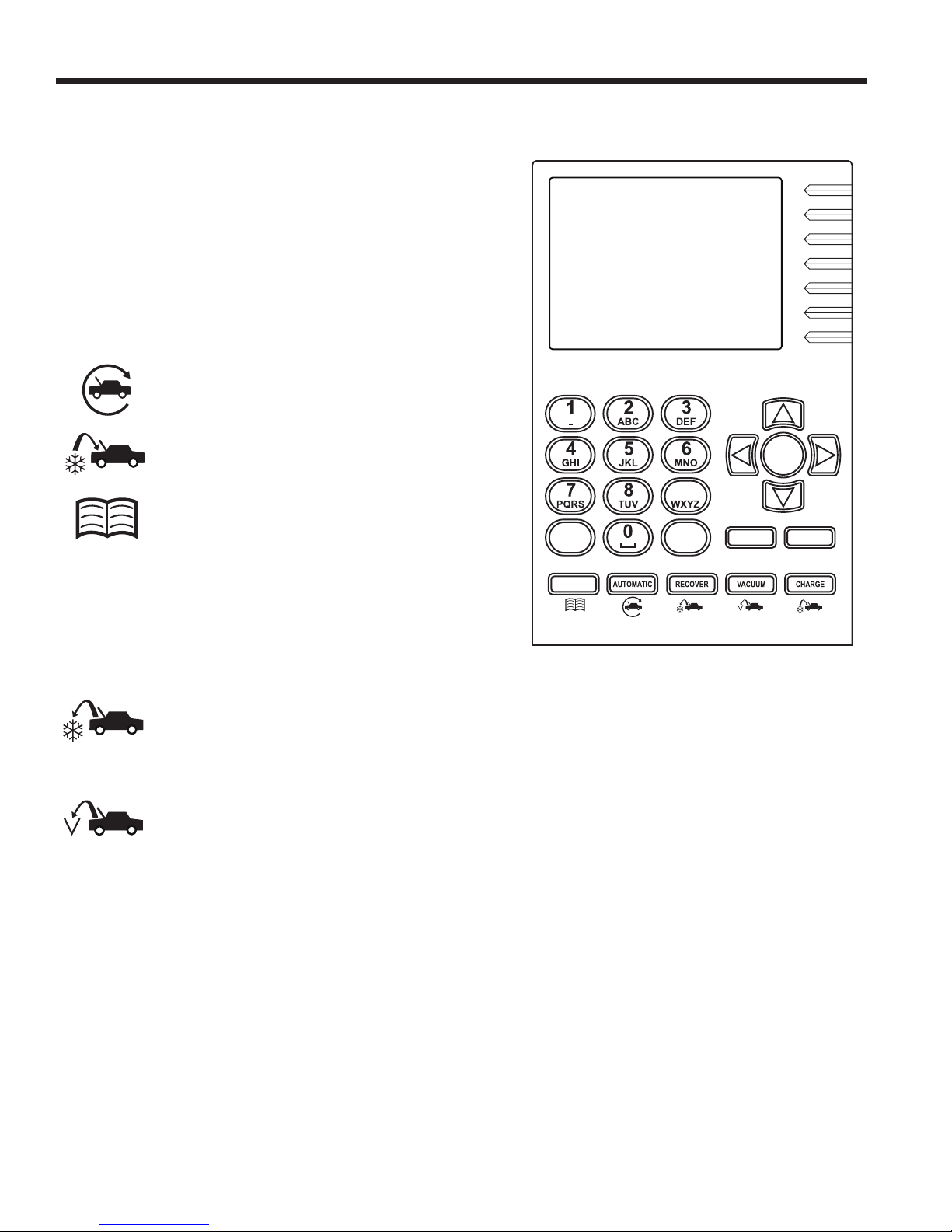
Introducción
Funciones del panel de control
FLECHA HACIA ARRIBA mueve la selección de un elemento
del menú al elemento anterior; sube el volumen del audio.
FLECHA HACIA ABAJO: mueve la selección de un elemento
del menú al elemento siguiente; baja el volumen del audio.
FLECHA HACIA LA DERECHA: va a la siguiente pantalla;
adelanta el video.
FLECHA HACIA LA IZQUIERDA: va a la pantalla anterior;
atrasa el video.
AUTOMATIC activa un menú para congurar
una secuencia automática de recuperación/
vacío/prueba de fugas/carga.
CHARGE activa una secuencia para cargar el
sistema de A/C de un vehículo con una cantidad
de refrigerante programada.
DATABASE
con la capacidad de carga según el modelo
del vehículo.
ESC regresa la secuencia de la prueba a la pantalla anterior;
o responde una consulta.
HELP muestra información relacionada a la pantalla actual.
MENU accede a funciones adicionales y congura parámetros.
OK resalta el elemento del menú; responde una consulta; o
inicia el video.
RECOVER activa una secuencia para recuperar
refrigerante del sistema de A/C del vehículo.
proporciona información relacionada
9
HELP MENU
DATABASE
Teclado del panel de control
OK
STOP ESC
STOP interrumpe la función activa. Presione una vez para
pausar, dos veces para nalizar.
VACUUM activa una secuencia para crear un
vacío en el sistema de A/C del vehículo para
sacar el aire y la humedad.
8
Page 69

Introducción
Presione el número
en el teclado que
coincida con
el número de
la función que
desea acceder.
1
2
3
4
5
6
Confg unid
Manten de unidad
Función serv de AC
Bas dato
Actulz
Menú servcio
9
HELP MENU
DATABASE
ESC
STOP ESC
OK
1
2
3
4
5
6
Ecual mang
Limp sistema
Datos trab serv
Automátic
Recuper
Vacío
ESC
En este ejemplo, otra
forma de seleccionar
Recuperación es
presionando el botón
RECOVER en el
panel de control.
Notas sobre elementos del menú principal no descritas en este manual:
• Actulz - use este elemento del menú para actualizar aplicación, base de datos o URL por WiFi.
Para usar las funciones Wi-Fi, el rewall de red debe permitir el acceso a:
http://connectedservicesvc-equip3.bosch-automotive.com/api/RepairResults/upload y
http://9e864a0ddceb616e594a-77285b2f7a214aa453b5113bdf793358.r48.cf1.rackcdn.com
• Menú serv - para uso de centros de mantenimiento solamente
• Menú prod - para uso de fabricantes solamente.
• Administrador - para uso de fabricantes solamente.
581371 REV A
9
Page 70

Procedimiento de conguración inicial
Desempaque del kit de accesorios
Saque el kit de accesorios de la caja y retire el empaque de plástico.
Kit de accesorios
Adaptador de la
Peso de calibración
Tapón y tubo de llenado
manguera de llenado
del tanque
Aceite para bomba
de vacío
16 oz
Botella de drenaje
de aceite
Cable DLC externo
Instalación de la botella de drenaje
de aceite
Mantenga la botella de drenaje de aceite derecha e inserte el
conector en el hueco detrás de la cubierta hasta que encaje
en su lugar.
Tarjeta SD
Bolsa que contiene SDS, información de EPA,
información de MACS y una lista de centros
de servicio.
10
Botella de
drenaje de
aceite
Page 71

Procedimiento de conguración inicial
Importante:
•
Este procedimiento puede llevar varias horas. Realice
este procedimiento de conguración inicial ANTES
de que se necesite la máquina para realizar el primer
servicio de A/C del vehículo.
•
Durante la conguración inicial, la máquina pasa por
los siguientes pasos. Cualquier cambio a estos valores
después de la conguración inicial puede realizarse
mediante el menú Conguración de la unidad.
Encendido de la máquina
1.
Desenrolle el cable de energía de la manija y conéctelo a
una toma de corriente de voltaje adecuado y conectado
a tierra.
2.
Ubique la máquina de manera que el operador pueda
acceder fácilmente al tapón y al interruptor de energía
principal. Verique que las ranuras del ventilador en la
parte posterior de la máquina no estén obstruidas.
3. Bloquee las ruedas delanteras.
4. Encienda el interruptor de energía principal.
PRECAUCIÓN: la máquina está
programada para ejecutar el procedimiento
de conguración según se describe aquí.
Para prevenir lesiones personales, NO
ponga a funcionar la máquina sin el tapón
del puerto de llenado de aceite instalado,
pues la bomba de vacío se presuriza durante
el funcionamiento normal.
Selección del idioma
El operador selecciona el idioma para los avisos de la pantalla.
1. Use las echas ARRIBA o ABAJO para desplazarse por
los idiomas disponibles.
2. Presione OK para congurar el idioma seleccionado.
Acuerdo de licencia del usuario nal
Acepte el acuerdo de licencia del usuario nal para continuar
con la conguración inicial.
Unidad de medida
Programe la máquina para que exhiba las unidades de medida
en kilogramos o libras. La pantalla predeterminada está
en inglés.
Nota: si se selecciona inglés, el peso será mostrado en
unidades métricas (por estándar SAE J2843); las presiones
y temperaturas serán mostradas en unidades inglesas.
1. Utilice las teclas de echa ARRIBA o ABAJO para des-
plazarse por unidades métricas o inglesas.
2.
Presione OK para elegir la unidad de medida mostrada.
581371 REV A
11
Page 72

Procedimiento de conguración inicial
Información del concesionario
Esta máquina tiene la capacidad de imprimir información de
recuperación, vacío, carga y limpieza para cada vehículo
examinado. Se puede obtener una impresión cada vez que
la pantalla de visualización muestre OK=PRN La información
ingresada en los campos a completar en la pantalla Info conces
aparecerá en cada impresión.
1. El cursor está destellando en el campo Cód conces. Consulte
la Figura 1.
2. Presione la tecla MENU y aparecerá un teclado virtual como
se muestra en la Figura 2. Nota: se puede conectar un teclado
USB estándar a la máquina para introducir información.
3. Utilice las echas en el teclado de la máquina para despla-
zarse en el teclado virtual. Presione OK para ingresar un
carácter. El cursor se moverá al siguiente carácter.
4. Presione la tecla MENU para salir del teclado virtual. Utilice las
teclas de echa para moverse al siguiente campo. Presione
OK para guardar los datos cuando se hayan llenado los
campos aplicables. Presione ESC cuando termine.
Cód conces
Garaje
Direcc
Cdad
Tel
Fax
E-Mail
Figura 1
Figura 2
12
Utilice las teclas de
echa en el teclado
virtual para mover
el cursor dentro del
campo a completar.
Utilice las teclas de
echa en el teclado
de la máquina
para cambiar el
teclado virtual.
OK
Page 73

Procedimiento de conguración inicial
Conguración de fecha y hora
La máquina se programa en la fábrica según la fecha y zona
horaria locales, en base al reloj de 24 horas.
Nota: la fecha cambia únicamente desplazándose por un
día completo.
1. Utilice las teclas de echa hacia la IZQUIERDA y hacia la
DERECHA para modicar los minutos mostrados.
2. Utilice las teclas de echa hacia ARRIBA y ABAJO para
modicar la hora mostrada.
3. Presione OK para aceptar la fecha y hora.
Vacío de servicio
Siga las instrucciones para conectar las mangueras de servicio
de la máquina a los puertos de almacenamiento y abra los
acoples de servicio. La máquina realiza un vacío de 5 minutos
para eliminar el aire de la tubería interna y el ISV (depósito de
almacenamiento interno).
Cuando se le indique, presione OK para continuar con la
Conguración inicial.
Ajuste del llenado del tanque
El operador puede aceptar el peso predeterminado de la
máquina de 3,5 kg de refrigerante almacenado en el depósito de
almacenamiento interno (ISV), o bien puede ajustar la cantidad.
La cantidad máxima permitida de refrigerante nuevo es de
6,8 kg, lo que deja espacio para una recuperación adicional.
La cantidad mínima es de 1,8 kg.
1.
Seleccione AJUSTE LLENADO TANQ del menú Cong Unid.
2.
La máquina muestra la cantidad predeterminada
de refrigerante:
TANK LEVEL (NIVEL DEL TANQUE)
03,500 KG
3.
Presione OK para aceptar la cantidad predeterminada o
utilice el teclado para ingresar una cantidad y presione OK.
581371 REV A
13
Page 74

Procedimiento de conguración inicial
Llenado del tanque
1.
Conecte un tanque fuente R-1234yf a la manguera de
llenado del tanque en la parte posterior de la máquina.
Apriete con la mano la manguera de llenado del tanque.
Consulte la Figura 3.
Nota: la manguera de llenado del tanque y el puerto de
acceso del tanque tienen roscas de giro hacia la izquierda.
2. Abra la válvula del tanque.
3.
Coloque el tanque fuente en el estante en la parte posterior
de la máquina, orientado para suministrar refrigerante líquido
a la conexión. Ajuste la correa de sujeción alrededor del
tanque fuente. Verique que el tanque no restrinja el ujo
de aire de la ventilación.
4. La máquina muestra:
CANT DE LLENAD
XX,XXX
CONECT TANQ ABAST A MANG LLENADO
5.
Presione OK. La máquina controla el refrigerante en el
tanque fuente para vericar que sea R-1234yf y que no esté
contaminado, y muestra las siguientes pantallas:
CALENTAR
CALIBRACIÓN EN PROGRESO
IDENTIFICACIÓN DE GAS
PUREZA DE REFRIGERANTE ACEPTABLE
Después de terminar los pasos anteriores, la máquina
comienza a llenar el depósito de almacenamiento interno (ISV).
6. La máquina se detiene automáticamente cuando alcanza
el nivel predeterminado de llenado del tanque, o cuando el
tanque fuente está vacío. Para detener el llenado del tanque
antes de que alcance el nivel predeterminado, seleccione
ESC; presione OK para continuar.
7.
Si se utiliza un tanque no rellenable, la máquina debe mostrar
TANQ FUENTE VACÍO antes de que se deseche el tanque.
Figura 3
Correa
Manguera
de llenado
del tanque
14
Page 75

Procedimiento de conguración inicial
Registro de la máquina
Cuando aparece la pantalla de Activación del producto,
siga las instrucciones en pantalla para registrar la máquina.
1.
Abra un navegador web en una computadora personal.
Ingrese la dirección web mostrada en la pantalla Proceso
activación en la máquina.
Introduzca su nombre de usuario y contraseña para
conectarse al sitio de Internet.
Si es la primera vez que visita el sitio, haga clic en el
botón REGISTER (Registro) para crear un nombre de
usuario y una contraseña.
2.
En la máquina, presione OK. La máquina muestra
campos para la clave de activación del producto y el
código de activación.
3.
Ingrese la clave de activación del producto en el campo
correspondiente en la página web. Esto genera un
código de activación.
4.
Ingrese el código de activación en la pantalla de la
máquina y presione OK.
Nota: se requiere el uso de mayúsculas. Se puede
conectar un teclado USB estándar a la máquina para
introducir información.
5. Anote el código y la clave de activación del producto y
guárdelos en un lugar seguro.
El no registrar
y activar la
máquina durante
los 30 días
siguientes del
encendido
inicial hará que
la máquina se
bloquee y deje
de funcionar.
La clave de
activación
del producto
se mostrará
en este
campo.
6. Presione OK.
581371 REV A
15
Page 76

Menú de conguración
Elementos opcionales del menú
de Conguración
Muchas de las funciones incluidas en el procedimiento
de Conguración inicial también se pueden acceder
mediante el menú de Conguración. Aquí se explican
las funciones adicionales del menú de Conguración.
1. Presione la tecla MENU.
2.
Seleccione MENÚ CONFIG de las opciones
de menú.
Conguración de alarma
1.
Seleccione CONFIG ALARMA del menú Cong Unid.
2.
Presione el botón OK para ENCENDER y APAGAR
el "bip" del audio.
Conguración de BlueTooth
Esta opción de menú programa la máquina para
detectar y conectar con el U-Scan™ VCI (interfaz de
comunicaciones del vehículo).
Conexión de un U-Scan a máquina de
recuperación, reciclado y recarga de
AC Robinair
1.
Conecte el U-Scan en el conector OBDII del vehículo.
2.
Seleccione la opción CONFIG DE BLUETOOTH
en el menú de conguración.
3. Seleccione DESCUBRIR VCIS y presione OK
• Descubre y enumera dispositivos BlueTooth.
•
La detección elimina todo excepto U-Scan. Hay un
límite de una conexión.
•
Conecta U-Scan con la máquina. La información
será guardada para que las conexiones futuras
sean automáticas.
• Opción para ver número de serie y otra información
de la VCI conectada.
• Desconecta una VCI existente. La información será
borrada para las conexiones futuras.
4.
Siga las instrucciones de la pantalla. Al nal del
proceso de identicación, la pantalla mostrará una
lista de los VCI que fueron identicados.
5. Seleccione la VCI adecuada de la lista y presione
OK. El proceso de emparejamiento tardará
varios segundos.
Nota: El número de serie del VCI U-Scan se encuentra
en el empaque del U-Scan.
16
Page 77

Menú de conguración
Vista del número de serie del VCI conectado
Seleccione Mostrar VCI conectado, y presione OK. La
pantalla mostrará el número de serie de la VCI con el que
está emparejado actualmente.
Desconexión de una VCI
Seleccione Desconectar VCI, y presione OK. Siga las
instrucciones de la pantalla.
Información del sistema
Al seleccionar este elemento del menú se mostrará el
nivel de revisión, el número de serie y otra información
acerca del software y la máquina.
Prueba de conexión a red
La información de esta opción del menú puede ser
usada para resolver problemas de conexión a red.
La dirección MAC de la tarjeta WiFi se puede ver
en este menú.
Selección de formato de fecha
Seleccione el orden de visualización para los
componentes básicos del año calendario - día,
mes y año. Presione OK.
Valores de Ethernet
Active o desactive DHCP para el puerto Ethernet.
Objetivo de carga predenido
Use este elemento del menú para cambiar la cantidad
de carga predeterminada que aparece en la pantalla de
programación de carga.
1.
Seleccione OBJ CARGA PREDEFINIDO del menú
Congur Unid.
2.
La máquina muestra la cantidad actual predeterminada
de carga:
0,000 KG
3.
Presione OK para aceptar la cantidad predeterminada o
utilice el teclado y las echas para cambiar la cantidad.
Presione OK para continuar o ESC para salir.
Legal
Esta opción del menú muestra el acuerdo de licencia del
usuario nal.
581371 REV A
17
Page 78

Conguración de WiFi
Use esta opción del menú de Conguración para programar la
máquina para descubrir y conectarse a una red inalámbrica. Las
actualizaciones de software se pueden obtener de esta manera.
Nota: se visualiza el indicador de intensidad de la señal WiFi
en la pantalla de espera cuando la máquina está conectada a
una red WiFi.
1. Presione la tecla MENU y seleccione Conguración WiFi
en el menú Cong Unid.
2. Seleccione Buscar redes.
3. Utilice las echas ARRIBA o ABAJO para seleccionar una
red WiFi. Presione OK.
4. Aparece una solicitud de contraseña:
• para WPA/WPA2 – introduzca la contraseña
• para WEP – se requieren los siguientes caracteres:
- contraseña WEP de 10 unidades –
1 + 0 × [contraseña de 10 dígitos]
[índice = 1, 40 bits (hexadecimal de 10 dígitos)]
- contraseña WEP de 5 caracteres –
4 + [contraseña de 5 dígitos]
[índice = 4, 40 bits (5 caracteres)]
- contraseña WEP de 26 dígitos –
3 + 0 × [contraseña de 26 dígitos]
[índice = 3, 104 bits (hexadecimal de 26 dígitos)]
- contraseña WEP de 13 caracteres –
2 + [contraseña de 13 dígitos]
[índice = 2, 104 bits (13 caracteres)]
Por ejemplo, para una contraseña WEP de 104 bits, se
usa el formato siguiente:
1 + 0 × [contraseña de 26 caracteres hexadecimales]
Denición:
1 = índice de teclas
+ = delimitador de índice de teclas
0× = indicador de entradas hexadecimales
Nota: en la máquina de recuperación, reciclado y recarga
para sistemas de A/C R-1234yf, el carácter “+” es una de
las teclas con varios caracteres bajo el “1”.
18
Page 79

Conguración de WiFi para redes ocultas
1. Presione la tecla MENU y seleccione Conguración WiFi
en el menú Cong Unid.
2. Seleccione Conectar a redes ocultas.
3. Introduzca el SSID de la red y presione OK.
581371 REV A
19
Page 80

Menú de conguración
4.
Seleccione el modo de autenticación de la red y presione OK.
5. Seleccione el tipo de cifrado de la red y presione OK.
6. Aparece una solicitud de contraseña:
• para WPA/WPA2 – introduzca la contraseña
• para WEP – se requieren los siguientes caracteres:
- contraseña WEP de 10 unidades –
1 + 0 × [contraseña de 10 dígitos]
[índice = 1, 40 bits (hexadecimal de 10 dígitos)]
- contraseña WEP de 5 caracteres –
4 + [contraseña de 5 dígitos]
[índice = 4, 40 bits (5 caracteres)]
- contraseña WEP de 26 dígitos –
3 + 0 × [contraseña de 26 dígitos]
[índice = 3, 104 bits (hexadecimal de 26 dígitos)]
- contraseña WEP de 13 caracteres –
2 + [contraseña de 13 dígitos]
[índice = 2, 104 bits (13 caracteres)]
Por ejemplo, para una contraseña WEP de 104 bits, se
usa el formato siguiente:
1 + 0× [contraseña de 26 caracteres hexadecimales]
Denición:
1 = índice de teclas
+ = delimitador de índice de teclas
0× = indicador de entradas hexadecimales
Nota: en la máquina de recuperación, reciclado y recarga
para sistemas de A/C R-1234yf, el carácter “+” es una de
las teclas con varios caracteres bajo el “1”.
Base de datos
Utilice esta opción de menú para ver la información de
refrigerante en el vehículo.
1.
Desde el menú principal, seleccione DATABASE DE DATOS.
2.
Siga las indicaciones en pantalla para seleccionar la
información del vehículo.
La pantalla mostrará las especificaciones de refrigerante
recomendadas por el fabricante para el vehículo seleccionado.
20
Page 81

Menú de conguración
Entrada VIN
Después de seleccionar cualquier función de servicio de A/C,
se debe ingresar información del vehículo y el número de
identicación del vehículo (VIN) en la máquina.
La máquina ofrece varias formas de introducir el VIN:
•
VCI con conexión de cable - conecta al puerto OBDII
del vehículo.
•
VCI BlueTooth - conecta un U-Scan al puerto OBDII
del vehículo.
Nota: la opción para obtener el VIN mediante BlueTooth
solo aparecerá si U-Scan se ha conectado con la máquina
para A/C.
•
Entrada manual - Utilice las teclas de echa para seleccionar
un campo y el teclado virtual para introducir información.
La entrada de VIN se usará para determinar la información del
vehículo y el servicio utilizando la base de datos.
La información que se introduce en este punto del menú se
guarda en Datos de trabajo de servicio.
Captura de pantalla de la presión del A/C
La función de Captura de pantalla de la presión del sistema
A/C se usa para registrar las presiones de funcionamiento del
sistema del vehículo. Los datos captados se pueden ver, imprimir
o exportar a una tarjeta SD como parte del registro de servicio.
Se captan los siguientes valores:
• Presión del lado alto del sistema
• Presión del lado bajo del sistema
• Temperatura del ambiente
• Humedad en el ambiente
Al inicio de los procesos de RECUPERACIÓN y AUTOMÁTICO,
se ofrece la opción para hacer una Captura de pantalla de la
presión del sistema de A/C para registrar la condiciones de
funcionamiento antes del servicio. Al nal de los procesos de
CARGA y AUTOMÁTICO, se vuelve a ofrecer la opción para
registrar las condiciones de funcionamiento después del servicio.
Aunque los datos se pueden imprimir en el momento de la
captura, también se pueden almacenar, imprimir o exportar con
el registro de servicio creado en los procesos AUTOMÁTICO,
RECUPERACIÓN o CARGA.
Después de completar la función de Captura de pantalla de la
presión del A/C, la máquina realizará la compensación de las
mangueras y la limpieza de las mangueras como parte de las
funciones CARGA o AUTOMÁTICO. Esto es necesario para
reducir la pérdida de carga debido a la captura de pantalla de
la presión del A/C.
581371 REV A
21
Page 82

Función del servicio de A/C
Impresiones
Una vez nalizada cada función
Los datos de la última función que acaba de completarse pueden
imprimirse desde la pantalla de resultados al presionar OK en
el panel de control de la máquina. Consulte Figura 4.
Después de que se haya completado y salido
del servicio
Se puede imprimir un resumen del servicio completo desde
Datos de trabajo de servicio:
1. Presione MENU en el panel de control de la máquina.
2.
Seleccione FUNC SERV DE A/C y luego DATOS
TRAB SERV.
3. Las opciones son:
• VER REG TRABAJO — se muestra una lista de VIN.
Utilice la echa ARRIBA o ABAJO para resaltar el VIN
sobre el cual desea imprimir los datos de servicio.
Presione OK para imprimir los datos de
la función que acaba de completarse.
Figura 4
• MOVER REG TRAB — siga las instrucciones de esta
opción para transferir todos los archivos a una tarjeta
SD. Los 100 registros más recientes también serán
guardados en Datos de trabajo de servicio.
• ENVIAR REG TRAB — siga las instrucciones de esta
opción para transferir todos los archivos a un servidor.
Los 100 registros más recientes también serán guardados
en Datos de trabajo de servicio.
•
COPIAR REG TRAB — ver "Datos de trabajo de servicio"
en la página 26.
Nota: los registros de trabajo se deben transferir a una PC para
el almacenamiento permanente. La tarjeta SD se borrará si se
deja en la máquina de A/C durante una actualización de red.
Nota: Consulte "Datos de trabajo de servicio" en la página 26.
22
Page 83

Ecualización de manguera
Función del servicio de A/C
Este elemento del menú de función de servicio de A/C dirige al
usuario a través de la limpieza de las mangueras de servicio
después de ejecutar el sistema de A/C para realizar diagnósticos.
Utilice esta función cuando las mangueras de servicio estén
conectadas, pero no haya refrigerante en el sistema.
Seguir las indicaciones de la ecualización de mangueras evita
que quede parte de la carga de refrigerante del vehículo en las
mangueras de servicio, una situación que puede causar una
pérdida de rendimiento de A/C en sistemas de baja capacidad.
1. Coloque la palanca de velocidades del vehículo en park (estacionamiento) o neutral (neutro) con el freno de emergencia
activado. Conecte la manguera del lado bajo al sistema de
A/C; desconecte la manguera de lado alto.
2. Arranque el vehículo. Coloque el sistema de A/C al máximo.
Durante esta operación, el lado alto y el lado bajo se conectan
internamente, permitiendo que la mayoría de refrigerante
pueda ser regresado al lado bajo del sistema de A/C.
3. Al indicarse, desconecte la manguera del lado bajo y apague
el vehículo. Presione OK.
4. La máquina realiza una limpieza interior de su tubería, y luego
hace sonar una alarma cuando ha terminado. Presione OK
para salir.
1
2
3
4
5
6
Pantalla 1 del menú de Función del servicio
de A/C
Ecual mang
Limp sistema
Datos trab serv
Automático
Recuper
Vacío
ESC
Figura 5
È
581371 REV A
23
Page 84
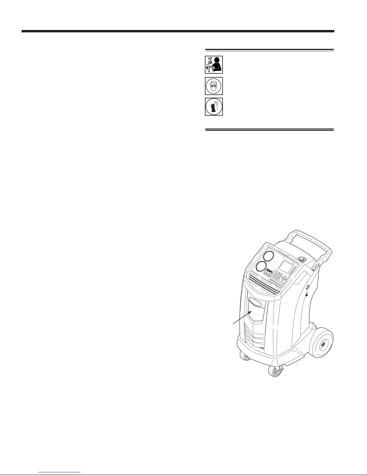
Función del servicio de A/C
Limpieza del sistema
Esta máquina proporciona un método para eliminar el aceite
al forzar el refrigerante líquido a través del sistema de A/C o a
través de los componentes del sistema de A/C. Un adaptador
especial de descarga (que se compra por separado) accede
al sistema de A/C en el bloque del compresor. Después de
la limpieza, la máquina recupera el refrigerante y lo ltra por
medio del circuito de reciclaje, regresándolo a los niveles de
pureza de SAE.
Los sistemas de A/C varían y pueden requerir la adaptación y el
lavado de los componentes individuales. Consulte los boletines
de servicio según sea necesario durante este procedimiento.
Conguración
1.
Verique que la botella de drenaje de aceite en la parte frontal
de la máquina esté vacía. Consulte la Figura 6. Recupere
el refrigerante según se describe en este manual.
2.
Cierre las válvulas del acoplador de mantenimiento
y desconecte las mangueras de los puertos de acceso
del vehículo.
3. Cierre la válvula en el tanque fuente externo.
Nota: durante este procedimiento, se cargan hasta
(7.7 lb.)
el ciclo de limpieza se detiene antes de que se complete y la
válvula fuente externa se abre, la unidad automáticamente
agrega refrigerante al ISV y no habrá espacio para recuperar
el refrigerante usado para la limpieza.
de refrigerante en el sistema de A/C del vehículo. Si
3,5 kg
ADVERTENCIA: para prevenir
lesiones personales mientras
trabaja con el refrigerante,
lea y siga las instrucciones y
advertencias de este manual,
y utilice equipos de protección
como gafas y guantes.
Notas:
La máquina debe tener por lo menos 4,6 kg
•
(10.1 lb.) de refrigerante disponible en el ISV
(como se indica en la pantalla) para la carga.
Si un corte de corriente accidental u otra
•
falla interrumpe el proceso de purga, utilice el
modo Recuperar para eliminar el refrigerante
del vehículo.
4.
Retire el dispositivo de expansión del sistema de A/C y
vuelva a conectar los conectores para crear una desviación.
5.
Desconecte las líneas de refrigerante del compresor
del vehículo.
6. Conecte el adaptador del bloque del compresor (del kit de
limpieza) al lado del sistema del bloque del compresor.
7.
Congure los conectores del bloque para brindar una limpieza
de curso inverso y hacia adelante del refrigerante, que uye
desde la máquina a través de la manguera roja de conexión
de descarga alta. Abra el acoplador rojo de servicio.
8.
Conecte la caja del ltro al lado de retorno deseado del
bloque del adaptador y a la manguera azul de descarga
baja. Abra el acoplador azul de servicio.
9.
Verique que un ltro de limpieza esté correctamente instalado
en la caja del ltro de limpieza. Abra la válvula de aislamiento
de la manguera.
24
Botella
de
drenaje
de aceite
Figura 6
Page 85

Función del servicio de A/C
Instrucciones de funcionamiento
1.
Seleccione LIMP SISTEMA del menú de Función de servicio
de A/C.
2. Lleve a cabo la función de ingreso de VIN
3.
Seleccione INICIO para aceptar el tiempo de limpieza
predeterminado de 10 minutos o ingrese el tiempo de limpieza
deseado con el teclado y seleccione INICIO.
4.
Las siguientes pruebas son automáticas y se realizan según
lo requerido por SAE J2843:
• vacío que funcione entre 5 y 20 minutos para alcanzar
el nivel correcto
• prueba de aumento de vacío de 5 minutos
• 15% de carga
•
prueba de fugas manual utilizando un detector de fugas
certicado en conformidad con \SAE J2913
Notas:
.
ADVERTENCIA: NO desconecte los
acopladores de servicio durante el proceso
de limpieza. El refrigerante se saldría por
los conectores y exponerse a esto puede
ocasionar lesiones personales.
•
La prueba de fugas J2843 tiene la nalidad de encontrar
una fuga considerable antes de la carga, por razones
de seguridad. No tiene la nalidad de reemplazar otras
prácticas de pruebas de fugas establecidas.
• La carga de 15 % se recupera automáticamente antes
de recargar la cantidad programada.
• Para evitar fallas falsas, las temperaturas del sistema
del vehículo y la máquina de recuperación deben estar
dentro de los ± 5 °C.
Consulte el manual de servicio del vehículo para obtener
instrucciones especícas sobre el vehículo.
5. La máquina limpia el sistema durante el tiempo designado
y luego ingresa al modo de recuperación.
6.
El aceite que se ha recolectado, se drena dentro de la botella
de drenaje de aceite graduada. Retire la botella y mida el aceite.
Deseche el aceite según lo establecen las leyes de su
jurisdicción. Es responsabilidad del usuario determinar si un
material es desecho peligroso al momento de desecharlo.
7. Cuando la máquina muestre
LIMPIEZA COMPLETA
cierre los acopladores de servicio, retire las mangueras y
vuelva a ensamblar el sistema de A/C del vehículo según su
estado original.
8. Abra la válvula del tanque fuente.
9. Vacíe y vuelva a recargar el sistema del vehículo según las
instrucciones de este manual.
PRECAUCIÓN: para evitar daños al vehículo,
use una herramienta para la inyección de
aceite para reemplazar el aceite del sistema.
La limpieza elimina todo el aceite del sistema,
excepto lo que queda en el compresor.
Sugerencias
de funcionamiento
Si el ltro de limpieza externo está tapado, la
unidad mostrará:
POSIBLE OBSTRUCCIÓN
FILTRO PURGA O VÁLVULA DE
ACOPLADOR CERRADA
ESC PARA RECUPERAR
REFRIGERANTE PRES OK
Después de que se limpió o reemplazó el ltro,
reinicie la limpieza del sistema desde el menú
de Función del servicio de A/C.
LIMPIEZ SISTEMA
P REINTEN
581371 REV A
25
Page 86

Función del servicio de A/C
Datos de trabajo de servicio
La máquina almacena los datos de servicio para los VIN que
se registraron en la pantalla de Entrada de VIN. Los resultados
completos del servicio pueden imprimirse al nalizar el servicio
completo del vehículo al seleccionar el VIN del menú DATOS
TRAB SERV.
Los resultados del servicio incluyen:
• VIN
• datos del vehículo, si se ingresaron
• tipo de servicio
• temperatura ambiente y humedad
• pureza de refrigerante
• cantidad recuperada
• tipo de vaciado
• tiempo de vaciado
• vaciado completado
• modo de carga
• cantidad cargada
• tiempo de purga
• código cifrado
Figura 7
La pantalla muestra las opciones de Datos de
trabajo de servicio.
1. Presione MENU en el panel de control de la máquina.
2. Seleccione FUNCIÓN SERV DE AC.
3. Seleccione DATOS TRAB SERV.
4. Consulte Figura 7. Las opciones son:
•
VER REG TRAB — se muestra una lista de VIN. Utilice
la echa ARRIBA o ABAJO para resaltar el VIN sobre
el cual desea imprimir los datos de servicio.
• MOVER REG TRAB — siga las instrucciones de esta
opción para transferir todos los archivos a una tarjeta
SD. Los 100 registros más recientes también serán
guardados en Datos de trabajo de servicio.
• ENVIAR REG TRAB — siga las instrucciones de esta
opción para transferir todos los archivos a un servidor.
Los 100 registros más recientes también serán guardados
en Datos de trabajo de servicio.
• COPIAR REG TRAB — siga las instrucciones de esta
opción para seleccionar el trabajo de servicio y copiar
todos los archivos a una tarjeta SD.
Nota: los registros de trabajo se debe transferir a una PC para
el almacenamiento permanente. La tarjeta SD se borrará si se
deja en la máquina de A/C durante una actualización de red.
Figura 8
La pantalla muestra algunos datos disponibles
en Ver registro de trabajo.
26
Page 87

Función del servicio de A/C
Procedimiento para Mover registros de trabajo
1.
Levante la pestaña de caucho en el lado superior derecho
de la máquina e instale una tarjeta SD desbloqueada
en la ranura para tarjetas SD.
2.
Seleccione MOVER REG TRABAJO del menú de Función
del servicio del sistema de A/C.
3.
Después de que los archivos se hayan movido a la tarjeta
SD con éxito, la máquina muestra:
ARCHIVO TRANSFERIDO
PRESIONE OK PARA CONTINUAR
4. Presione OK y retire la tarjeta SD.
5.
Transfiera los archivos de una tarjeta SD a una
computadora personal para el almacenamiento.
Nota: el registro de trabajos se debería transferir a una
PC para el almacenamiento permanente. Una tarjeta SD
se borrará si se deja en la máquina de A/C y se realiza
una actualización de red.
6.
Las pantallas MOVER REG TRAB y ENVIAR REG
TRAB ahora mostrarán que no hay archivos disponibles
para mover.
Procedimiento para Copiar registros de trabajo
1.
Levante la pestaña de caucho en el lado superior derecho
de la máquina e instale una tarjeta SD desbloqueada
en la ranura para tarjetas SD.
2. Seleccione COPIAR REG TRAB del menú de Función
del servicio del sistema de A/C.
3.
Seleccione el registro de trabajo que desea copiar y
presione OK. Consulte Figura 9.
4. Después de que el archivo se haya copiado a la tarjeta
SD con éxito, la máquina muestra:
Figura 9
La pantalla muestra los registros de trabajo
disponibles para copiar.
Figura 10
La pantalla muestra que se copió el registro de
trabajo a la tarjeta SD.
COPIA EXITOSA
Consulte Figura 10. Presione OK y retire la tarjeta SD.
5.
Transfiera los archivos de una tarjeta SD a una
computadora personal para el almacenamiento.
Nota: el registro de trabajos se debería transferir a una
PC para el almacenamiento permanente. Una tarjeta SD
se borrará si se deja en la máquina de A/C y se realiza
una actualización de red.
581371 REV A
27
Page 88

Función del servicio de A/C
Automático
La función automática permite al usuario programar una
recuperación automática, un vacío, una prueba de fugas y / o
una secuencia de carga. Una secuencia automática total puede
tardar hasta una hora.
1.
Conecte las mangueras de servicio a los puertos de servicio
del vehículo y abra los acopladores.
2. Seleccione AUTOMÁTICO.
3.
Realizar la función de entrada VIN. Si se encuentra una
entrada de base de datos coincidente, el monto de la carga
recomendada se rellenará automáticamente.
4. La máquina muestra
1
2
HP
LP
ADVERTENCIA: para prevenir
lesiones personales mientras trabaja
con el refrigerante, lea y siga las
instrucciones y advertencias de
este manual, y utilice equipos de
protección como gafas y guantes.
Nota: si se encuentran problemas durante la
secuencia automática, la máquina “sonará” tres
veces, las luces rojas en la parte delantera de la
máquina parpadearán y la lectura del panel de
control identicará detalladamente el problema
que encontró. La secuencia permanece en pausa
hasta que el usuario decida cómo continuar.
3
5
Utilice las teclas numéricas del teclado para seleccionar 1-3
para el sistema de A / A del vehículo.
Para la selección 5, acepte el valor predeterminado o
introduzca un valor y pulse OK.
Nota: Si el valor predeterminado es 0.000 kg, debe introducirse
un valor para continuar.
5. Seleccione un tiempo de vacío:
•
Pulse OK para aceptar el tiempo de evacuación
predeterminado o introduzca el tiempo de vacío deseado
con las teclas numéricas y pulse OK.
• La máquina tira de un vacío en el sistema de A / C por
el tiempo programado. Durante el proceso de vacío, la
máquina realizará una purga de aire si es necesario.
6. La máquina muestra
HP + LP
Refrigerant
0.000 kg
¿SE HA UTILIZADO ESTA MÁQUINA
PARA SERVIR UN SISTEMA QUE UTILIZA
ACEITE PAG?
EN CASO AFIRMATIVO, SELECCIONE OK PARA
REALIZAR UN LAVADO DE MANGUERA O SI NO,
ESC PARA CONTINUAR CARGANDO.
•
Si se selecciona OK, la máquina solicita un procedimiento
de lavado de la manguera. Conecte las mangueras de
servicio de lado alto (rojo) y bajo (azul) a los puertos de
almacenamiento y abra las válvulas de acoplamiento.
Presiona OK. Mueva las mangueras de servicio a los
28
Page 89

Función del servicio de A/C
puertos de servicio del vehículo y abra los acopladores.
Presiona OK.
•
Si se selecciona ESC, la máquina continúa a RECOVER
(o VACUUM si no hay presión para una recuperación).
7. Si se detecta presión
• La máquina comprueba el refrigerante en el vehículo
para vericar que es R-1234yf y no contaminado, lo cual
es requerido por SAE J2843. Si la lectura de pureza
es aceptable, la máquina dará la opción de ejecutar
presiones de diagnóstico antes de la recuperación.
•
Pulse OK para ejecutar presiones de diagnóstico;
Presione ESC para continuar con RECOVER.
• Si seleccionó OK, siga las indicaciones para encender
el vehículo y congurar el sistema de A / C de acuerdo
con los requisitos de prueba de funcionamiento del A / A
del manual de servicio. Presione OK después de que la
presión se estabilice. Vuelva a pulsar OK para imprimir
datos; Presione ESC para continuar con RECOVER.
Mangueras de
servicio conectadas
a los puertos de
almacenamiento
Figura 11
8.
La máquina realiza el proceso VACUUM
como se seleccionó previamente en el paso 5.
9. La máquina realiza el proceso CARGA:
• Prueba de fugas de vacío de 10-20 minutos (aplica el
vacío, comprueba si el vacío está decaído.
•
Prueba de fugas de pre-carga (carga el 15% de la carga
total, solicita al usuario que realice una prueba de fugas
manual usando un detector de fugas certicado por
SAE J2913).
• Carga el sistema de A / C.
10. Después de que la máquina cargue el sistema, la máquina
de nuevo da la opción de ejecutar una prueba de presiones
de diagnóstico.
•
Pulse OK para ejecutar presiones de diagnóstico;
Presione ESC para continuar.
11. Siga las indicaciones para igualar el refrigerante líquido en
el sistema de A / C del vehículo para obtener la máxima
exactitud de carga.
12.
Cuando finalice la secuencia, cierre las válvulas de
acoplamiento de lado alto (rojo) y de lado bajo (azul).
PRECAUCIÓN: si deja abierta la válvula del
acoplador del lado bajo (azul) o del lado alto
(rojo) durante el proceso de limpieza de las
mangueras, el sistema volverá a sacar el
refrigerante del vehículo.
13. Cuando se le solicite, retire las mangueras de servicio del
sistema de A / C e instálelas en los puertos de almacenamiento
de la máquina. Seleccione ok para comenzar a limpiar las
mangueras. Esto prepara la máquina para el próximo servicio.
14.
La máquina muestra un resumen de las acciones realizadas
durante la secuencia automática.
581371 REV A
29
Page 90

Función del servicio de A/C
Recuperación
1.
Vacíe la botella de drenaje de aceite antes de comenzar una
recuperación. Desinstale la botella de drenaje de aceite de
la máquina tirando de la botella verticalmente; no haga un
movimiento de giro o balanceo. Consulte la Figura 12.
2.
Conecte las mangueras de lado alto (rojo) y de lado bajo
(azul) al sistema de A/C del vehículo.
3. Abra las válvulas del acoplador en las mangueras al rotar
los collarines hacia la derecha.
4.
Seleccione la función de recuperación presionando el
botón RECOVER en el panel de control o seleccionando
Recuperación en el menú de Función del servicio de A/C.
5. Lleve a cabo la función de ingreso de VIN.
6.
La máquina revisa el refrigerante en el vehículo para vericar
que sea R-1234yf y que no esté contaminado. Si la pureza del
refrigerante es aceptable, la máquina comenzará el proceso
de recuperación. El sonido de clic indica que el solenoide
se está abriendo y cerrando, esto es normal.
ADVERTENCIA: para prevenir
lesiones personales mientras trabaja
con el refrigerante, lea y siga las
instrucciones y advertencias de
este manual, y utilice equipos de
protección como gafas y guantes.
7. La máquina muestra:
¿EJECUTAR PRESIONES DE DIAGNÓSTICO?
Para almacenar y/o imprimir las presiones de diagnóstico
en este punto, siga las indicaciones para encender el
vehículo y congure el sistema de A/C según los requisitos
de rendimiento del sistema de A/C que se encuentran en el
manual de servicio. Presione OK.
La máquina muestra cuándo capturar los valores y cuándo
se pueden imprimir.
8.
La máquina ejecuta un ciclo de limpieza automática para limpiar
refrigerante interno que haya quedado en su tubería interna.
9. Cuando el sistema se haya recuperado a 0 psi, la bomba
de vacío arranca y funciona hasta que la recuperación
esté completa.
10.
Después de que se complete el drenaje de aceite, la máquina
mostrará un resumen del gas recuperado. En este punto,
usted puede imprimir la información de recuperación y
diagnósticos de prerrecuperación al seleccionar OK. El
peso recuperado que se muestra puede variar dependiendo
de las condiciones de ambiente y no se debe utilizar como
indicador de exactitud de la balanza.
Botella
de
drenaje
de aceite
Figura 12
11. La cantidad de aceite que se quitó del sistema de A/C es la
cantidad de aceite nuevo que se debe cargar en el sistema
de A/C después de que se completa el vaciado.
• Sólo use aceite nuevo para reemplazar el aceite que se
eliminó durante el proceso de reciclado.
•
Deseche el aceite utilizado conforme a las
regulaciones gubernamentales.
La recuperación está completa.
30
Page 91
Vacío
Función del servicio de A/C
1.
Conecte las mangueras de servicio a los puertos de servicio
del vehículo.
2.
Abra las válvulas del acoplador rotando los collarines hacia
la derecha.
3. Presione VACÍO.
4. Lleve a cabo la función de ingreso de VIN.
5. Presione OK para aceptar el tiempo de vaciado
predeterminado, o introduzca el tiempo de vaciado
deseado con las teclas numéricas y presione OK.
• La máquina genera un vacío en el sistema de A/C
durante la cantidad de tiempo programada. Durante
el proceso de vacío, la máquina realizará una purga
de aire, si se necesita.
•
La máquina se detiene cuando ha transcurrido la
cantidad de tiempo especicada. En este momento
usted puede imprimir información de vacío al seleccionar
OK. Presione ESC para volver al menú principal.
ADVERTENCIA: para prevenir
lesiones personales mientras trabaja
con el refrigerante, lea y siga las
instrucciones y advertencias de
este manual, y utilice equipos de
protección como gafas y guantes.
IMPORTANTE: la unidad extrae el vacío
profundo del sistema de A/C del vehículo para
eliminar el aire y la humedad de ebullición
que se puede encontrar en el sistema.
Lograr un vacío profundo suciente depende
en gran medida de la condición del aceite
de la bomba de vacío. Cambie el aceite de
la bomba de vacío después de 10 horas de
funcionamiento de la bomba; cambie el aceite
de la bomba de vacío con más frecuencia
si el equipo se usa en sistemas de A/C
que han estado abiertos por períodos de
tiempo prolongados.
581371 REV A
Nota: cuando la bomba de vacío tiene 10 horas
de uso, la máquina pide un cambio de aceite.
Seleccione OK para proceder con el cambio de
aceite, seleccione
proceso de vacío. Consulte "Mantenimiento del
aceite de la bomba de vacío" en la página 36.
ESC
para continuar con el
31
Page 92
Función del servicio de A/C
Carga
Las siguientes pruebas son automáticas y se realizan según lo
requerido por SAE J2843:
• vacío que funcione entre 5 y 20 minutos para alcanzar el
nivel correcto
• prueba de aumento de vacío de 5 minutos
• 15% de carga
•
prueba de fugas manual utilizando un detector de fugas
certicado en conformidad con \SAE J2913
Notas:
• La prueba de fugas J2843 tiene la nalidad de encontrar
una fuga considerable antes de la carga, por razones de
seguridad. No tiene la nalidad de reemplazar otras prácticas
de pruebas de fugas establecidas.
• Para evitar fallas falsas, las temperaturas del sistema del
vehículo y la máquina de recuperación deben estar dentro
de los ± 5 °C.
Consulte el manual de servicio del vehículo para obtener
instrucciones especícas sobre el vehículo.
1.
Conecte las mangueras de servicio a los puertos de servicio
del vehículo y abra los acopladores.
ADVERTENCIA: para prevenir
lesiones personales mientras trabaja
con el refrigerante, lea y siga las
instrucciones y advertencias de
este manual, y utilice equipos de
protección como gafas y guantes.
2. Presione CHARGE.
3. Lleve a cabo la función de ingreso de VIN. Si se encuentra
una entrada de base de datos coincidente, el monto de la
carga recomendada se rellenará automáticamente.
4. La máquina muestra:
1
2
3
7
Utilice las teclas numéricas del teclado para seleccionar
un modo de carga HP, LP o HP/LP para el sistema de A/C
del vehículo.
Para la selección 7, acepte los valores predeterminados o
ingrese un valor y presione OK dos veces.
Nota: si el valor predeterminado es de 0,000 kg, se debe
ingresar un valor para continuar.
HP
LP
HP + LP
Refrigerante
0,000 kg
32
Page 93

Función del servicio de A/C
5. La máquina muestra:
ESTA MÁQ HA SIDO USADA PARA
DAR SERV A SIST USANDO ACTE PAG?
SI SÍ, SELEC OK PARA PURGA MANG O SI NO,
ESC PARA CONT CARGA.
Si se selecciona OK la máquina solicita un procedimiento de
limpieza de la manguera. Conecte las mangueras de servicio
del lado alto (rojo) y del lado bajo (azul) a los puertos de
almacenamiento y abra las válvulas del acoplador. Presione
OK. Si selecciona ESC, la máquina continúa con CHARGE.
6.
Conecte las mangueras de servicio a los puertos de servicio
del vehículo y abra los acopladores. Presione OK. La máquina
realiza pruebas automáticas en el sistema según lo requerido
por SAE J2843.
7.
Al ser indicado, realice una prueba de fugas manual
utilizando un detector de fugas certicado en conformidad
con SAE J2913. Una vez que se haya completado la prueba
de fugas, CHARGE continúa.
Nota: el proceso de carga incluye una prueba
de fugas de vaciado automático, después de la
cual el sistema se presuriza con una pequeña
cantidad de refrigerante para una prueba de
fugas manual.
Si mueve o golpea la máquina en este punto puede
provocar una carga incorrecta. Cuando el ciclo de carga se
aproxima al valor del peso deseado, la máquina disminuye
su velocidad. Cargará, se establecerá, cargará de nuevo,
se establecerá, etc.
8.
Una vez nalizada la CHARGE, la máquina lo guía a través
de una prueba de presiones de diagnóstico. Este proceso
se requiere para proporcionar las presiones del sistema
del vehículo para los datos de servicio de garantía
guardados e impresos.
9.
Siga las indicaciones para compensar el refrigerante líquido
en el sistema de A/C del vehículo para una precisión de
carga máxima.
10.
Cuando se le indique, cierre las válvulas del acoplador y retire
las mangueras de servicio del sistema de A/C. Instale las
mangueras en los puertos de almacenamiento de la máquina.
11. Presione OK para iniciar la limpieza de las mangueras y
preparar la máquina para el servicio siguiente.
12. Cuando las mangueras están limpias, la pantalla muestra
un resumen de los resultados de la carga, que se puede
imprimir presionando OK.
PRECAUCIÓN: si deja abierta la válvula del
acoplador del lado bajo (azul) o del lado alto
(rojo) durante el proceso de limpieza de las
mangueras, el sistema volverá a sacar el
refrigerante del vehículo.
Nota: los resultados completos del servicio pueden imprimirse
al nalizar el servicio completo del vehículo seleccionando el
VIN del vehículo del menú DATOS TRAB SERV.
El menú DATOS TRAB SERV se encuentra pulsando MENU y
seleccionando FUNC SERV DE A/C.
Ahora ya puede utilizar el sistema de A/C del vehículo.
581371 REV A
33
Page 94

Función del servicio de A/C
Purga mang
La selección de este elemento de menú hará que la máquina
limpie sus tuberías internas.
1. Cuando se le indique, conecte las mangueras de servicio
de la máquina a sus puertos de almacenamiento y abra las
válvulas del acoplador como se muestra en la Figura 13.
2. Controle el visor del nivel de aceite de la bomba de vacío y
verique que el nivel de aceite sea correcto.
3. Abra los acopladores de servicio girando los acopladores
hacia la derecha.
4.
La máquina realiza una limpieza interior de su tubería, y
luego hace sonar una alarma cuando ha terminado. Presione
OK para salir.
ADVERTENCIA: Para prevenir
lesiones personales:
Solo personal debidamente
•
preparado debe realizar las
inspecciones y reparaciones de
esta máquina.
Lea y siga las instrucciones y
•
advertencias de este manual,
y utilice equipos de protección
como gafas y guantes.
No ponga en funcionamiento
•
la máquina si se ha quitado la
cubierta.
Figura 13
34
Mangueras
de servicio
conectadas a
los puertos de
almacenamiento
Page 95
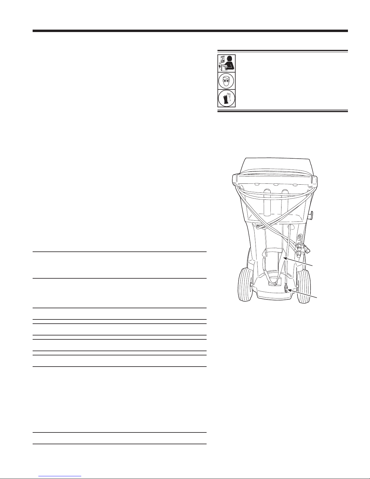
Mantenimiento de la unidad
Llen tanque
Este elemento del menú se utiliza para transferir refrigerante de
un tanque fuente al ISV. Este procedimiento funciona solamente
si el ISV contiene menos de la cantidad máxima de refrigerante
programada en Ajuste del llenado del tanque.
Nota: si un tanque fuente está conectado a la manguera de
llenado del tanque mientras que la máquina permanece inactiva,
la máquina automáticamente agrega refrigerante hasta el nivel
establecido durante el Ajuste del llenado del tanque.
1.
Conecte un tanque fuente R-1234yf a la manguera de
llenado del tanque en la parte posterior de la máquina.
Consulte Figura 14.
Nota: la manguera de llenado del tanque y el puerto de
acceso del tanque tienen roscas de giro hacia la izquierda.
2. Apriete con la mano la manguera de llenado del tanque.
3. Abra la válvula del tanque.
4.
Coloque el tanque fuente en el estante en la parte posterior
de la máquina, orientado para suministrar refrigerante líquido
a la conexión. Ajuste la correa de sujeción alrededor del
tanque fuente. Verique que el tanque no restrinja el ujo
de aire de la ventilación.
ADVERTENCIA: para prevenir
lesiones personales mientras trabaja
con el refrigerante, lea y siga las
instrucciones y advertencias de
este manual, y utilice equipos de
protección como gafas y guantes.
5.
Seleccione LLEN TANQUE del menú de mantenimiento
de la unidad. La máquina muestra:
CANT DE LLENAD
XX,XXX
CONECT TANQ ABAST A MANG LLENADO
6.
Presione OK. La máquina controla el refrigerante en el
tanque fuente para vericar que sea R-1234yf y que no esté
contaminado. La máquina muestra las siguientes pantallas:
CALENTAR
CALIBRACIÓN EN PROGRESO
IDENTIF GAS
PUREZA DEL REFRIGERANTE ACEPTABLE
y después de cinco segundos comienza a llenar el depósito
de almacenamiento interno (ISV).
7.
La máquina se detiene automáticamente cuando alcanza el
nivel predeterminado de llenado del tanque. Para detener
el llenado del tanque antes de que se alcance el nivel
predeterminado, seleccione ESC.
8.
Si utiliza un tanque no rellenable, la máquina debe mostrar:
Correa
Manguera
de llenado
Figura 14
Nota: una vez que el proceso de llenado del tanque
haya terminado, la pantalla no mostrará la misma
cantidad que el nivel de llenado programado.
La pantalla muestra la cantidad de refrigerante
que está disponible para la carga, que es
aproximadamente 0,91 kg menos que la cantidad
total de refrigerante en el tanque.
del tanque
TANQ FUENTE VACÍO
antes de que se descarte el tanque.
581371 REV A
35
Page 96

Mantenimiento de la unidad
Mantenimiento del aceite de la bomba
de vacío
1.
Seleccione MANTEN ACEITE BOMBA VAC del menú
de mantenimiento de la unidad o cuando se indique. La
pantalla muestra cuánto tiempo ha funcionado la bomba
de vacío desde el último cambio de aceite.
X HORAS X MINUTOS
¿CAMB ACEIT?
2. Presione OK. La máquina mostrará
PRECAUCIÓN: para prevenir lesiones
personales NUNCA ponga a funcionar la
máquina en ningún otro momento sin la tapa
del puerto de llenado de aceite instalada,
pues la bomba de vacío se presuriza durante
el funcionamiento normal.
CALENTANDO EL ACEITE PARA UN MEJOR
DRENAJE ESPERE
X:XX
La bomba de vacío funcionará durante 30 segundos para
calentar el aceite. La pantalla muestra
CAMB ACEIT
LIMPIE UNIDAD
ESP
mientras que el compresor funciona para eliminar cualquier
presión en la bomba de vacío.
3. Luego de que el compresor se detenga, abra lentamente
la tapa de llenado de aceite para vericar que no haya
presión en la máquina. Luego quite cuidadosamente la
tapa. Consulte Figura 15.
4. La pantalla muestra
DRENE ACEITE USADO
AÑADA 150 ML ACEITE NUEVO
PRESIONE OK PARA CONFIRMAR
PRESIONE ESC PARA SALIR
Retire la tapa del conector de drenaje de aceite y drene el
aceite a un recipiente adecuado para su desecho. Reemplace
la tapa y cierre bien.
Puerto y tapa de
llenado de aceite
Visor
Conector
de drenaje
de aceite
Figura 15
5.
Lentamente agregue unos 150 ml de aceite para bomba de
vaciado a la bomba través del puerto de llenado de aceite.
Presione OK para activar la bomba de vaciado.
6. La pantalla muestra
LLENE LA BOMBA HASTA EL CENTRO
DEL VISOR
PRESIONE OK PARA TERMINAR
Lentamente agregue aceite de vaciado de bomba a la
bomba de a través del puerto de llenado de aceite hasta
que el aceite llegue al centro del visor.
7. Instale la tapa en el puerto de llenado de aceite y cierre
bien. Presione OK para regresar al menú de mantenimiento
de la unidad.
36
Precaución: es responsabilidad del usuario
controlar el nivel y la pureza del aceite de
la bomba de vacío. Si el aceite contaminado
no se quita y se reemplaza de la bomba de
vacío, esta se dañará permanentemente.
Page 97

Mantenimiento de la unidad
Mantenimiento del ltro
El ltro está diseñado para atrapar el ácido y las partículas y
eliminar la humedad del refrigerante. Para cumplir con la exigencia
adecuada de eliminación de humedad y contaminantes, debe
reemplazar el ltro después de haber ltrado 150 kg (331 lb)
de refrigerante.
La máquina emite una advertencia cuando se han utilizado
100 kg (220 lb) de su capacidad de ltrado; la máquina se
bloquea y no funcionará cuando alcance la capacidad del ltro
de 150 kg (331 lb).
ADVERTENCIA: los componentes en la máquina están
bajo presión alta. Para prevenir lesiones personales,
el ltro únicamente cuando la máquina lo indique.
Revisión de la capacidad restante del ltro
1.
Seleccione MANTEN DEL FILTRO del menú de
mantenimiento de la unida o cuando la máquina lo indique.
La máquina muestra la cantidad de capacidad restante del
ltro hasta que la máquina se bloquee.
cambie
ADVERTENCIA: para prevenir
lesiones personales mientras trabaja
con el refrigerante, lea y siga las
instrucciones y advertencias de
este manual, y utilice equipos de
protección como gafas y guantes.
Precaución: para evitar daños al equipo,
utilice únicamente ltros Robinair nº 34724
auténticos en esta máquina. Todas las
pruebas de funcionamiento y reclamos se
basan en el uso de este ltro especíco.
2. Cuando se le indique, seleccione OK para cambiar el ltro;
seleccione ESC para continuar usando la máquina.
Reemplazo de los ltros y ensamble de la
manguera de muestra
1.
Si se seleccionó OK para cambiar el ltro, la máquina limpia
el ltro, luego indica que se ingrese el código del ltro nuevo.
Utilice el teclado para ingresar el número de serie que
aparece en el nuevo ltro y presione OK. Si
NÚMERO SERIE NO VÁLIDO
se muestra, signica que se ha introducido incorrectamente
el número de serie o que el ltro ya ha sido usado en
esta máquina.
2. La máquina muestra:
APAGAR UNIDAD
QUITAR TAPA Y REEMPL FILTR, IDENTIFIC
FILTRO, E
IDENTIFIC MUESTRA ENSAMBLE MANG
Apague la máquina. Retire la botella de aceite. Retire los
cuatro tornillos que sujetan la cubierta. Consulte Figura 16.
Retire los cuatro tornillos
que sujetan la cubierta.
581371 REV A
Figura 16
37
Page 98

Mantenimiento de la unidad
3.
Sostenga la cubierta en la parte posterior de la máquina
como se muestra en la Figura 17.
4.
Quite el ltro girándolo hacia la izquierda (tal como se
visualiza desde la parte inferior del ltro).
5.
Vea el ltro nuevo, verique que ambos empaques de anillo
estén lubricados y colocados correctamente en las ranuras
según se muestra en la Figura 18.
6.
Instale el nuevo ltro enroscándolo hacia la derecha. Verique
que el ltro esté colocado correctamente, como se muestra
en la Figura 19. Apriete el ltro a 20 N•m.
Figura 17
Filtro
H
E
L
9
P ME
O
K
N
U
S
T
OP
E
S
C
Sostenga
la cubierta
aquí
Empaque
de anillo
Figura 18
38
Ensamble
correcto
Figura 19
Ensamble
incorrecto
Page 99

Identicador de refrigerante
Mantenimiento de la unidad
El identicador de refrigerante prueba el refrigerante que pasa al
ISV para vericar que sea R-1234yf y que no esté contaminado.
Reemplace el ensamble de la manguera de muestra durante cada
cambio de ltro y también si así lo indica un mensaje de error
que diga que la manguera está obstruida. Consulte Figura 20.
1.
Desconecte el ensamble de la manguera de muestra existente
entre el solenoide y el identicador de refrigerante e instale
un nuevo ensamble de la manguera de muestra.
Nota: si el ltro toma un color que no sea blanco, quiere
decir que debe reemplazarse.
2. Quite el ltro de los soportes, mientras quita las lengüetas
de los conectores de goma.
3. Instale un nuevo ltro con la echa apuntando hacia arriba
como se muestra. Presione las lengüetas del ltro en los
conectores de goma.
4. Instale la cubierta de la máquina y encienda el interruptor
de energía.
Vericación de la calibración
Esta función se utiliza para garantizar que la balanza interna
de la máquina siempre esté calibrada. Durante esta prueba,
utilice únicamente la pesa de calibración que se proporciona
con la máquina.
Lengüeta
Identicador de
refrigerante
Ensamble de
la manguera
de muestra
Instale el nuevo
ltro con la echa
colocada como
↑
se muestra.
Figura 20
Reemplace el ensamble de la manguera de
muestra durante cada cambio de ltro.
1.
Seleccione VERIF CALIBRACIÓN del menú de
mantenimiento de la unidad. La máquina muestra:
SUJETE PESO A BASE DE MÁQUINA
PRESIONE OK PARA CONFIRMAR
PRESIONE ESC PARA SALIR
2. Consulte la Figura 21, y verique que el imán en la parte
inferior de la máquina esté limpio.
3. Fije el peso de calibración al imán que se encuentra en la
base de la máquina. Seleccione OK.
• Si la pantalla muestra:
PROCEDIM COMPLETO
la balanza está calibrada. Seleccione OK.
• Si la pantalla muestra:
CALIBRACIÓN RECHAZAD
la balanza no está calibrada. Comuníquese con un centro
de servicio de Robinair para recibir ayuda.
4. Retire el peso de calibración de la balanza.
Imán
Figura 21
581371 REV A
39
Page 100

Mantenimiento de la unidad
Manejo de refrigerante
Este elemento del menú de mantenimiento de la unidad muestra
la cantidad de refrigerante recuperado, cargado y reabastecido
(para la vida útil de la máquina), y ltrado desde el último cambio
de ltro.
Información sobre la purga de aire
Este elemento del menú de mantenimiento de la unidad muestra
la presión y la temperatura del depósito de almacenamiento
interno (ISV). Use esta información para revisar el ISV en cuanto
a presión excesiva.
Iluminación de fondo
Seleccione este elemento del menú de mantenimiento de la
unidad y utilice las echas izquierda y derecha para ajustar el
contraste en la pantalla de visualización.
Reemplazo de las mangueras de servicio
y/o los acopladores de servicio
Asegúrese de que se haya eliminado la presión de las mangueras
de servicio antes de desconectar una manguera o acoplador
de la máquina. Los manómetros deben indicar 0 psig o menos.
Si hay presión, recupere el refrigerante de las mangueras antes
de desconectar una manguera o acoplador.
1. La máquina realiza una segunda prueba de vacío durante
30 segundos para asegurar que las mangueras están vacías.
2. La máquina muestra:
DESCONECTE LAS MANGUERAS VIEJAS Y
REEMPLÁCELAS CON MANGUERAS NUEVAS
PRES OK PARA CONTINUAR
PRES ESC PARA SALIR
Retire y reemplace las mangueras de servicio viejas.
Presione OK.
3.
La unidad dirige al usuario para que conecte las
mangueras a los puertos de almacenamiento y presione
OK para iniciar el condicionamiento de la unidad.
4. Se realiza un vaciado de la unidad hasta que el nivel de
vacío llegue a 525 micrones.
5. La máquina está lista para el uso.
40
 Loading...