

Page 1
Page 2
ROBIN AME
ROBIN
TO
WISCONSZN
ROBIN
ENGINE MODEL CROSS REFERENCE
LIST
ROBXN
EY 08
EY15
EY 15V
EY20
EY20V
EY23
EY28
EY3
5
EY40
EY45V
EY2
1
EY44
EY 18-3
EY25
EY 27
EHll
EH12
EH15
EH17
EH2
1
EH25
EH30
EH3OV
EH34
EH34V
EH43V
EC13V
DY23
DY27
DY30
DY3 5
DY4
1
WISCONSIN
ROBIN
SIDE
VALVE
w
1-080
W1-145
w1-145v
W1-185
Wl-185V
W
1-230
W
1-280
W1-340
W
1-390
w
1
-450v
EY2 1
W
EY44W
EY25W
EY27W
EY
18-3
W
-
WO1-115
wo1-120
WQ1-150
WO1-170
wo1-210
WO 1-250
WO1-300
WO
1
-300v
WO
1-340
WO1-340V
WO1-43OV
TWO
CYCLE
WT1-125V
DZESEL
WRD1-230
WRD
1-270
WRD1-300
WRD1-350
WRD1-410
Page 3
Section
Title
ONTENTS
Page
1
.SPECIFICATIONS
......................................................................................
2JERFORMANCE
........................................................................................
2-
1
Maximum Output
...............................................................................
2-2
Maximum Torque At Maximum Output
..............................................
2-3
performance
curves
...........................................................................
3.
FEATURES
................................................................................................
4.GENERAL DESCRIPTION OF ENGINE COMPONENTS.....
....................
4-
1
Cylinder And Crankcase
.....................................................................
4-2
~~i~ ~~~~i~~
cover
...........................................................................
4-3
Crankshaft
.........................................................................................
4-4
Connecting Rod And Piston
.............................................................
4-5
Camshaft
...........................................................................................
4- 6
Valve Arrangement
.............................................................................
4-7
Cylinder Head
....................................................................................
4-8
Governor System
...............................................................................
4-9
Cooling System
..................................................................................
4- 10
Lubrication
.........................................................................................
4-
1 1 Ignition System
..................................................................................
4- 12
Carburetor
..........................................................................................
4- 13
Air Cleaner
.........................................................................................
4- 14
Balancers
............................................................................................
4- 15
Decompression System
......................................................................
1
2
2
2
2
4
4
4
4
5
5
5
6
6
6
7
7
8
8
8
9
9
4-
16
Sectional View Of Engine
..................................................................
10
12
12
12
13
28
42
42
42
43
5.DISASSEMBLY AND REASSEMBLY
......................................................
5-
1
Preparations And Suggestions
...........................................................
5-2
Special Tools
.....................................................................................
5-3
Disassembly Procedures
.....................................................................
5-4
Reassembly Procedures
......................................................................
6.MAGNETO
.................................................................................................
6-
1
Flywheel Magneto
..............................................................................
6-2
Basic Theory
......................................................................................
6-3
Wiring Diagram
..................................................................................
7.AUTOMATIC DECQMPRESSlON SYSTEM
.............................................
44
8.CARBURETQR
...........................................................................................
45
45
46
48
48
52
8-
1
Operation And Construction
..............................................................
8-2
Disassembly And Reassembly
....................
-
.......................................
g.STARTING SYSTEM
................................................................................
9-
1
Recoil Starter
.....................................................................................
9-
2
Electric Starting Motor (Option)
........................................................
Page 4
Page 5
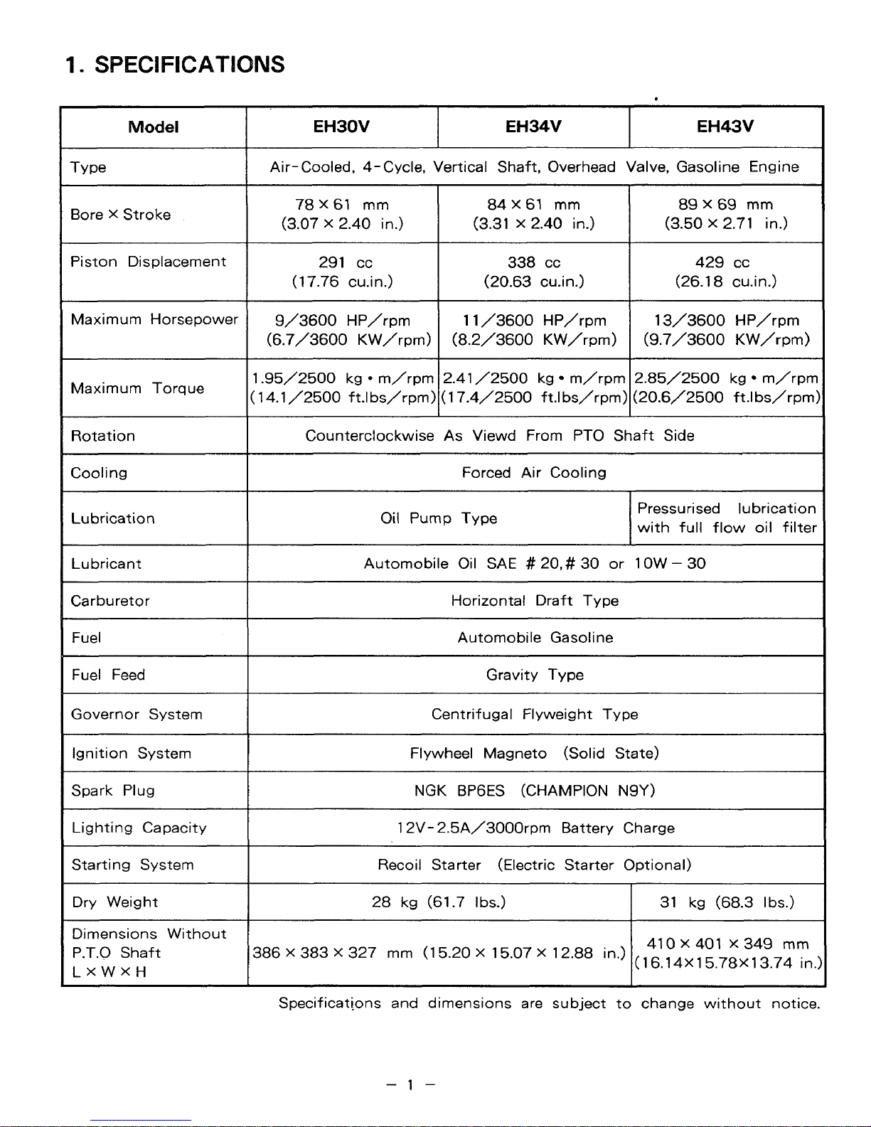
ECIFICATIONS
Model
Type
Bore
X
Stroke
Piston Displacement
Maximum Horsepower
Maximum Torque
Rotation
Cooling
Lubrication
Lubricant
Carburetor
Fuel
Fuel Feed
Governor System
Ignition System
Spark Plug
Lighting Capacity
Starting System
Dry Weight
Dimensions Without
P.T.0 Shaft
LXWXH
I
I
EH30V
EH34V
EH43V
1
I
Air-Cooled, 4- Cycle, Vertical Shaft, Overhead Valve, Gasoline Engine
78x61 mm
(3.07
X
2.40
in.)
291 cc
(1
7.76
cuin.)
9/3600
HP/rpm
(6.7/3600
KW/rpm)
1.95/2500
kg * m/rpm
14.1/2500 ft.lbs/rpm)
84
X
61
mm
(3.31
X
2.40
in.)
338
cc
(20.63
cu.in.1
1 1
/3600
HP/rpm
(8.2/3600
KW/rpm)
2.41
/2500
kg m/rpm
17-4/2500
ft.lbs/rpm>
89x69
mm
(3.50
X
2.71
in.)
429
cc
(26.1
8
cu.in.1
13/3600
HP/rpm
(9.7/3600
KW/rpm)
2.85/2500
kg
m/rpn.
(20.6/2500
ft.Ibs/rpm
Counterclockwise
As
Viewd From PTO Shaft Side
Forced Air Cooling
Oil
Pump Type
Pressurised lubrication
with full flow oil filtel
Automobile Oil SAE
#
20,#
30
or
1
OW
-
30
Horizontal Draft Type
Automobile Gasoline
Gravity Type
Centrifugal Flyweight Type
Flywheel Magneto (Solid State)
NGK BP6ES (CHAMPION N9Y)
12V- 2.5A/3000rpm Battery Charge
Recoil Starter (Electric Starter Optional)
28
kg (61.7 I bs.)
31
kg
(68.3
I
bs.)
386
X
383
X
327
mm
(1
5.20
X
15.07 X 12.88
in.)
410 X 401
X
349
mm
(1
6.1
4X
15.78X
13.74
in
Specificat[ons and dimensions are subject
to
change without notice.
-1-
Page 6
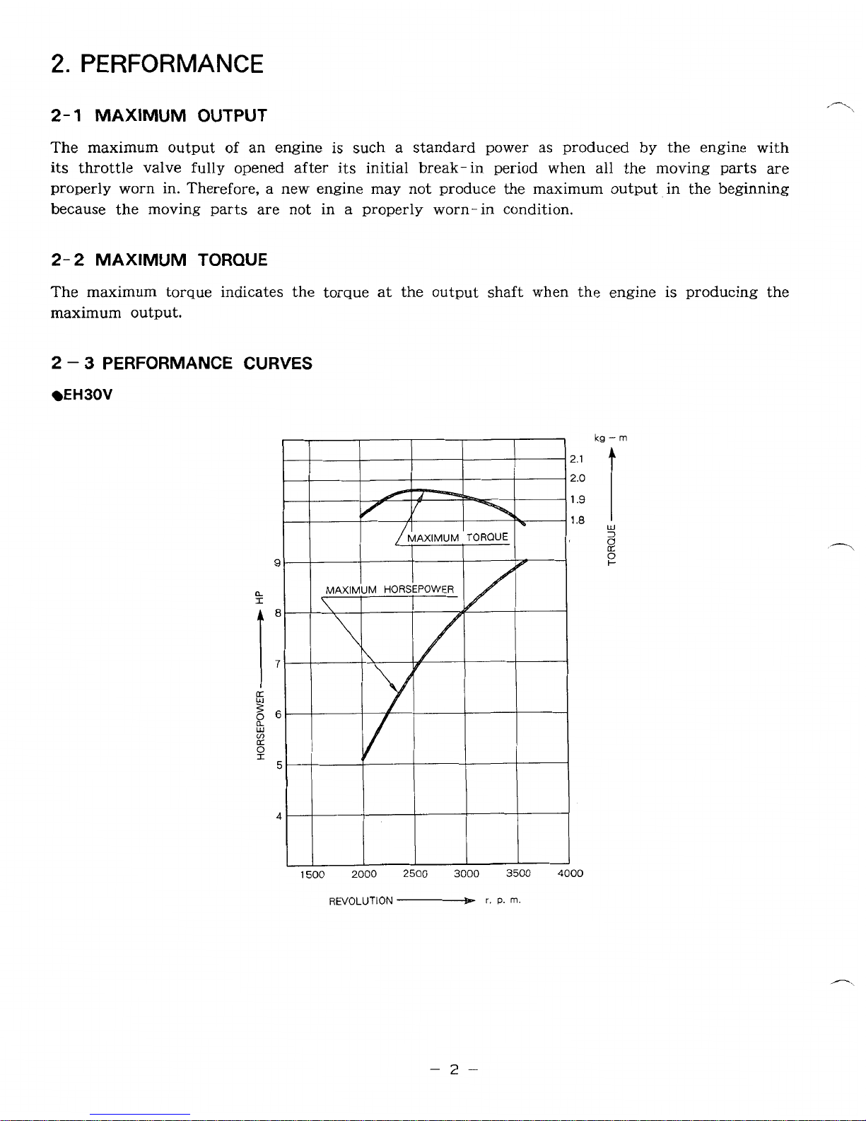
2.
PERFORMANCE
2-1
MAXIMUM OUTPUT
The maximum output of an engine
is
such a standard power as produced by the engine with
its
throttle valve fully opened after
its
initial break-in period when all the moving
parts
are
properly worn in. Therefore, a new engine may not produce the maximum output in the beginning
because the moving parts are not in
a
properly worn-in condition.
2-2
MAXIMUM TORQUE
The
maximum torque indicates the torque
at
the output shaft when the engine is producing the
maximum output.
2
-
3
PERFORMANCE CURVES
EH30V
a
1
kg
-
m
REVOLUTION
r.
P.
m
-2-
Page 7
0
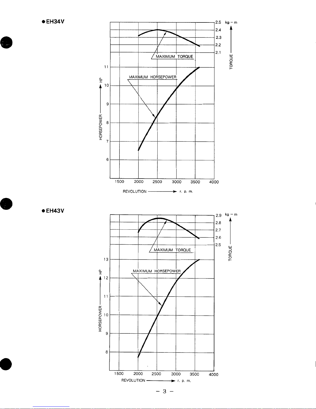
EH34V
I
11
10
9
a:
g8
a
W
cn
a:
0
I
7
6
0
EH43V
13
a
I
It
l2
11
10
9
8
n
I
MAXIMUM
TORQUE
I
10
2000
2500
3000
3500
4000
L
REVOLUTION
-
I.
P.
m.
2.5
kg-
m
2.4
2.2
2.1
w
3
8
P
L
1500
2(
=
MAXIMUM
TORQUE
0
2500
3000
3500
REVOLUTION
-+
r.
P.
m.
-3-
Page 8
3.
FEATURES
1.
The overhead valve design offers compactness, light weight and ideal combustion charastristics
resulting in more power from less fuel and prolonged engine life.
2.
The vibration free design with the twin balancer system and lighter reciprocating parts.
3.
The
parts
with extra long teeth and a blower housing and muffler cover made of resin laminated
"DAMPING
4.
The automatic decompression system offers easy, dependable starting.
5.
The muffler and carburator are located on opposite sides, making the arrangements for cooling
air flow much easier in the design
4.
GENERAL DESCRIPTION
such as a large capacity muffler, dual element air cleaner, helical type balancer gear
SHEET"
reduce noise to a minimum level.
of
power equipment.
OF
ENGINE COMPONENTS
,"-,
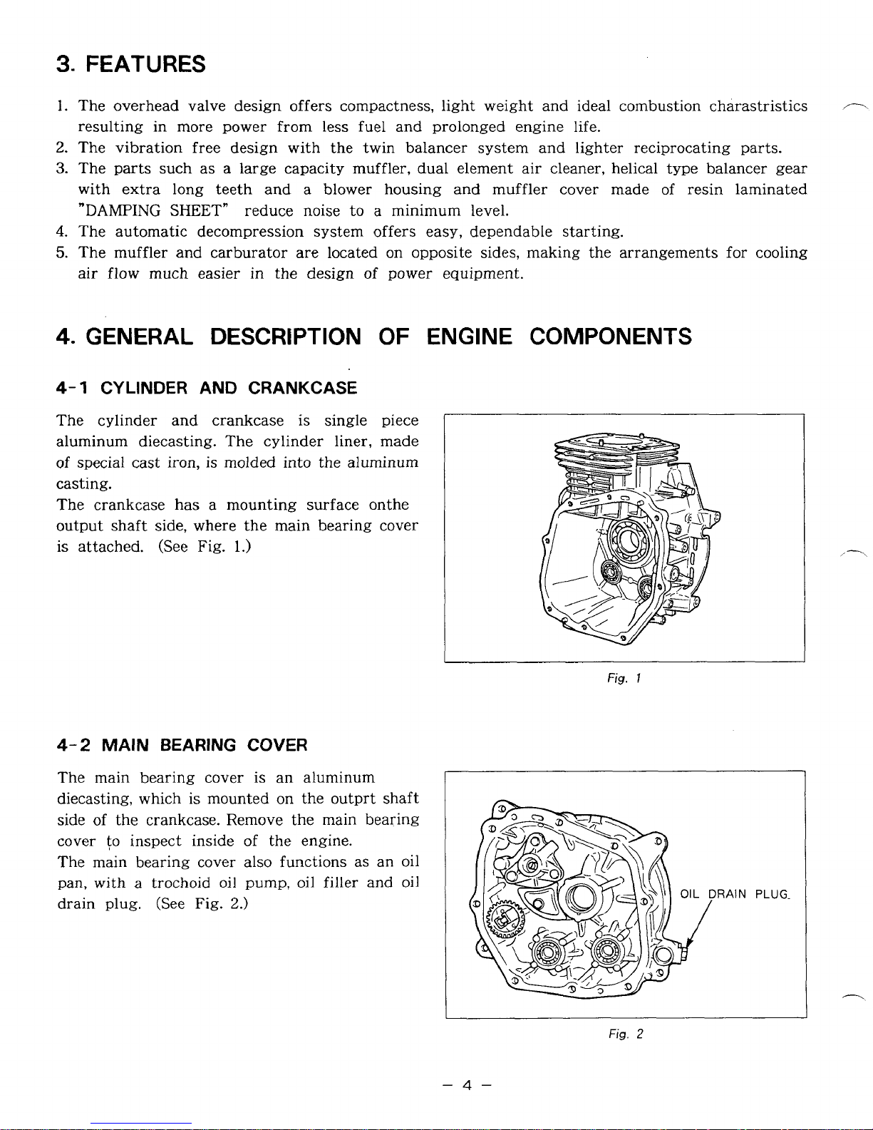
4-1
The cylinder and crankcase
aluminum diecasting. The cylinder liner, made
of
casting.
The crankcase has a mounting surface onthe
output shaft side, where the main bearing cover
is
4-2
The main bearing cover
diecasting, which
side of the crankcase. Remove the main bearing
cover
The main bearing cover also functions as an oil
pan, with
drain plug. (See Fig.
CYLINDER AND CRANKCASE
is
single piece
special cast iron, is molded into the aluminum
attached. (See Fig.
MAIN
to
BEARING
is
inspect inside
a
trochoid oil pump,
1.)
COVER
is
an aluminum
mounted on the outprt shaft
of
the engine.
oil
filler and
oil
2.)
Fig.
I
-4-
Fig.
2
Page 9
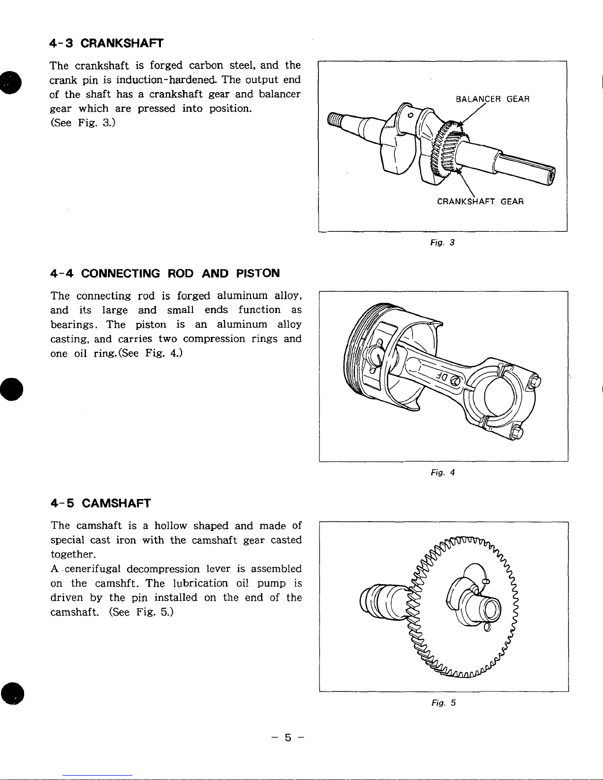
4-
3
CRANKSHAFT
The crankshaft
is
forged carbon steel, and the
e
crank pin is induction-hardened. The output end
of the shaft has a crankshaft gear and balancer
gear which are pressed into position.
(See Fig.
3.)
BALANCER GEAR
\
CRANKSHAFT
GEAR
Fig.
3
4-4
CONNECTING
ROD
AND
PISTON
The connecting rod is forged aluminum alloy,
and its large and small ends function as
bearings. The piston
is
an
aluminum -alloy
casting, and carries two compression rings and
one oil ring.(See
Fig.
4.)
Fig.
4
4-
5
CAMSHAFT
The camshaft
is
a hollow shaped and made
of
special cast iron with the camshaft gear casted
together.
A .
cenerifugal decompression lever
is
assembled
on the camshft. The lubrication
oil
pump
is
driven
by
the pin installed on the end
of
the
camshaft. (See
Fig.
5.)
Fig.
5
-5-
Page 10
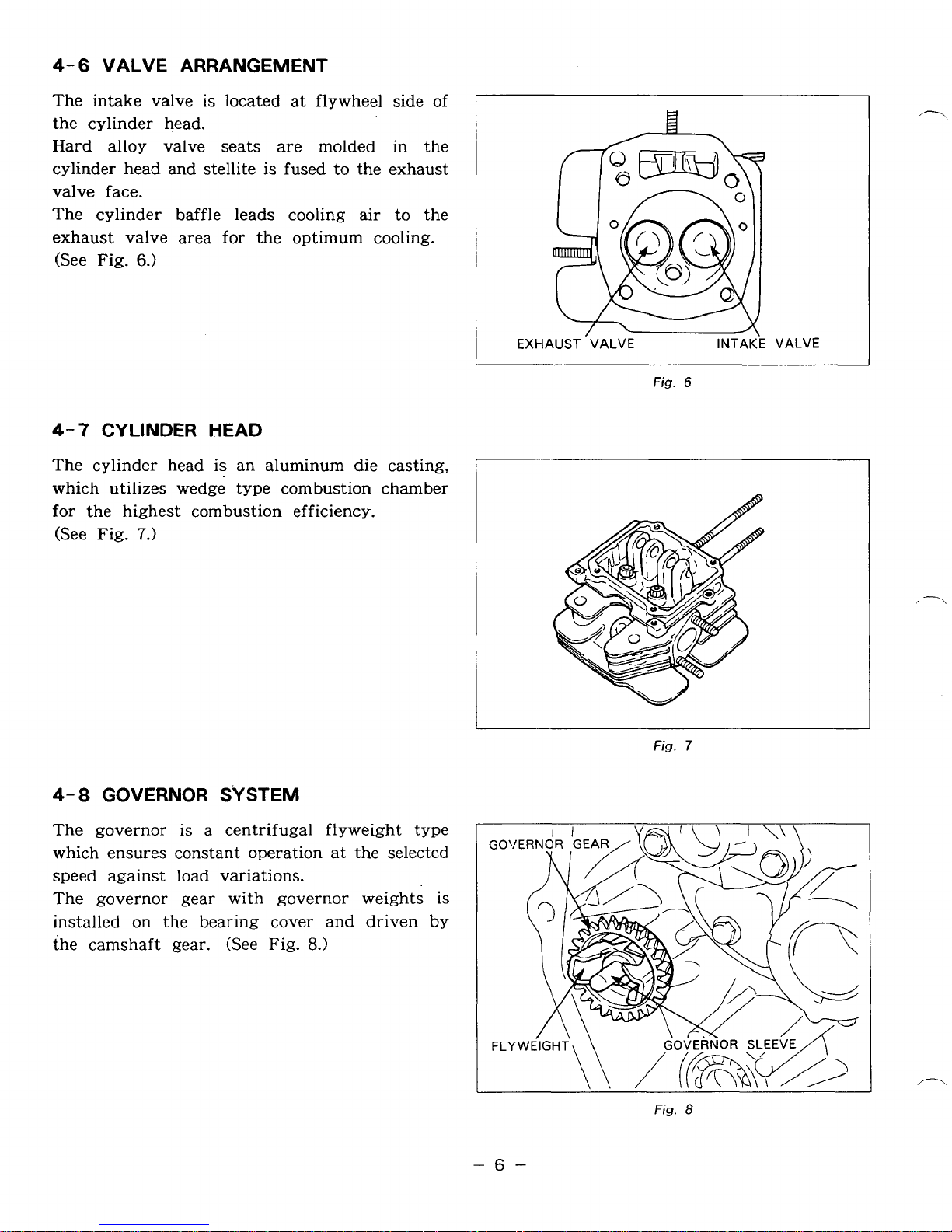
4-
6
VALVE ARRANGEMENT
The intake valve
is
located at flywheel side of
the cylinder head.
Hard alloy valve seats are molded in the
cylinder head and stellite is fused to the exhaust
valve face.
to
The cylinder baffle leads cooling air
the
exhaust valve area for the optimum cooling.
(See Fig.
4-7
The cylinder head
6.)
CYLINDER HEAD
is
an aluminum die casting,
which utilizes wedge type combustion chamber
for the highest combustion efficiency.
(See Fig.
7.)
EXHAUST 'VALVE
Fig.
6
INTAKE
VALVE
4-
8
GOVERNOR SYSTEM
The governor
which ensures constant operation
is
a centrifugal flyweight type
at
the selected
speed against load variations.
The governor gear with governor weights
installed on the bearing cover and driven by
the camshaft gear. (See Fig.
8.)
is
-6-
Fig.
Fig.
7
8
Page 11
4-9
COOLING
SYSTEM
The large fins on the flywheel provide sufficient cooling air capacity for the inlet and exhaust
area and cylinder.
a
The cylinder baffle helps the cooling air flow efficiently.
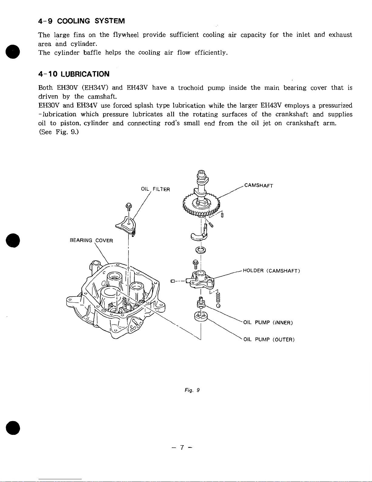
4-
10
LUBRICATION
Both EH30V (EH34V) and EH43V have a trochoid pump inside the main bearing cover that is
driven by the camshaft.
EH3OV and EH34V use forced splash
type
lubrication while the larger EH43V employs a pressurized
-lubrication which pressure lubricates all the rotating surfaces of the crankshaft and supplies
oil to piston, cylinder and connecting rod’s small end from the oil jet on crankshaft arm.
(See
Fig.
9.)
OIL FILTER
/
BEARING ,COVER
I
CAMSHAFT
Fig.
9
-7-
Page 12

4-
1
1
IGNITION
SYSTEM
The ignition system is a transistor controlled
magneto ignition system which cosists of a
flywheel and an ignition coil with a built in
transistor mounted on the crankcase.
This system has
an
ignition timing advance
for
the easy starting. (See
Fig.
10.)
Fig.
10
4-
12
CARBURETOR
The engines are equipped with a horizontal
draft carburetor that has
a
float controlled fuel
system and a fixed main
jet.
The carburetors are calibrated carefully
for
the
sure starting,
good
acceleration,
low
fuel
consumption and sufficient output.
For
the datails, refer
to
page
45,
section
"8
CARBURETOR".
(See Fig.
11.1
Fig.
1 1
4-
13
AIR
CLEANER
The air- cleaner is a heavy- duty type with a
dual element system. (See
Fig.
12.1
I
A
CLEANER BASE
I
ELEMENT
I
CAP
hUT
I
Fig.
12
-8-
Page 13
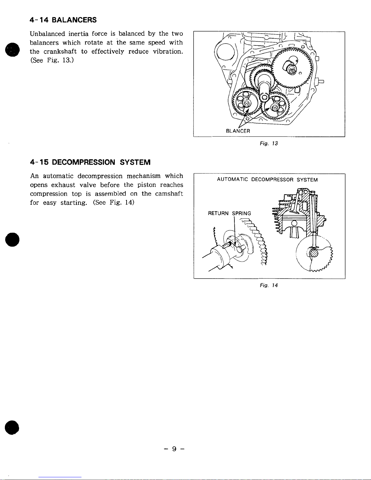
4-
14
BALANCERS
Unbalanced inertia force is balanced
by
the two
balancers which rotate at the same speed with
the crankshaft to effectively reduce vibration.
(See
Fig.
13.)
I
BLANCER
4-
15
DECOMPRESSION
SYSTEM
An
automatic decompression mechanism which
opens exhaust valve before the piston reaches
compression top is assembled on the camshaft
for easy starting. (See
Fig.
14)
Fig.
13
I
AUTOMATIC DECOMPRESSOR SYSTEM
*$
RETURN
SPRING
Fig.
14
-9-
Page 14
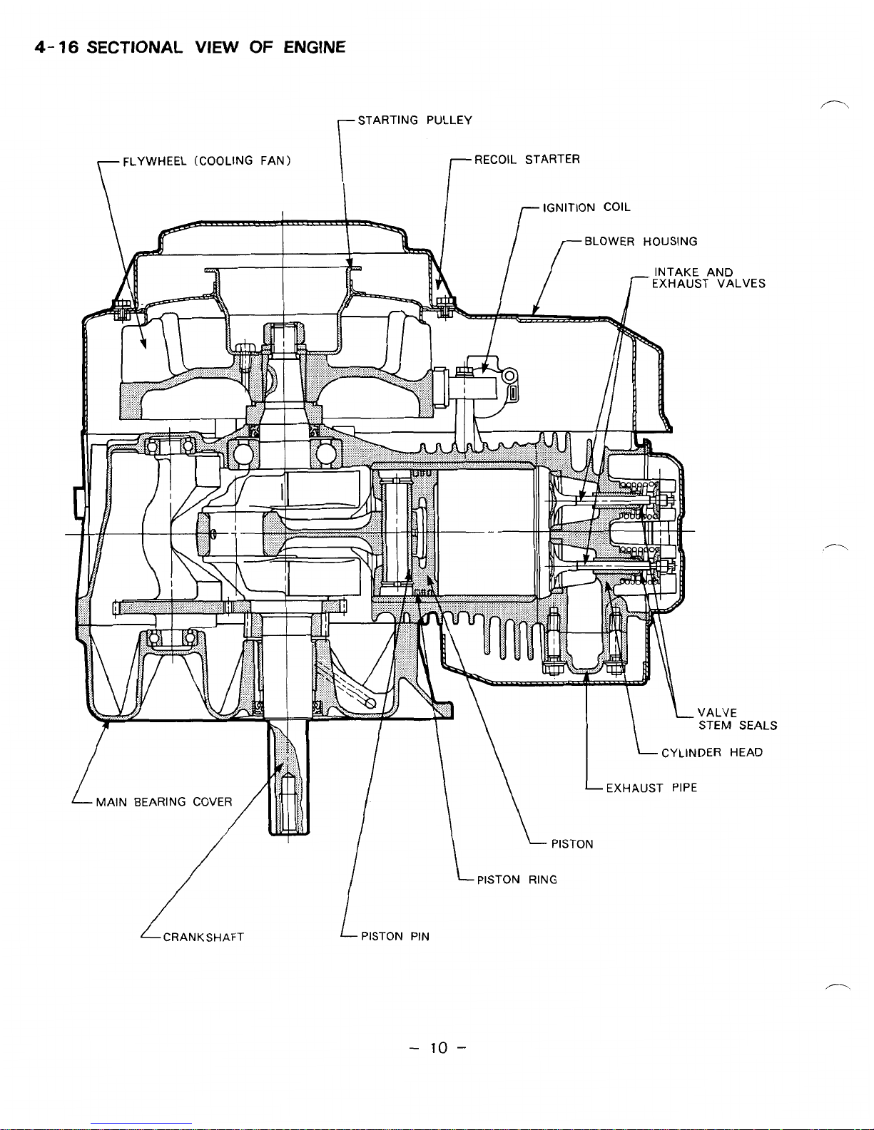
4-
16
SECTIONAL
VIEW
OF
ENGINE
r
FLYWHEEL (COOLING FAN)
r
STARTING PULLEY
I-
RECOIL STARTER
-
lo
-
Page 15
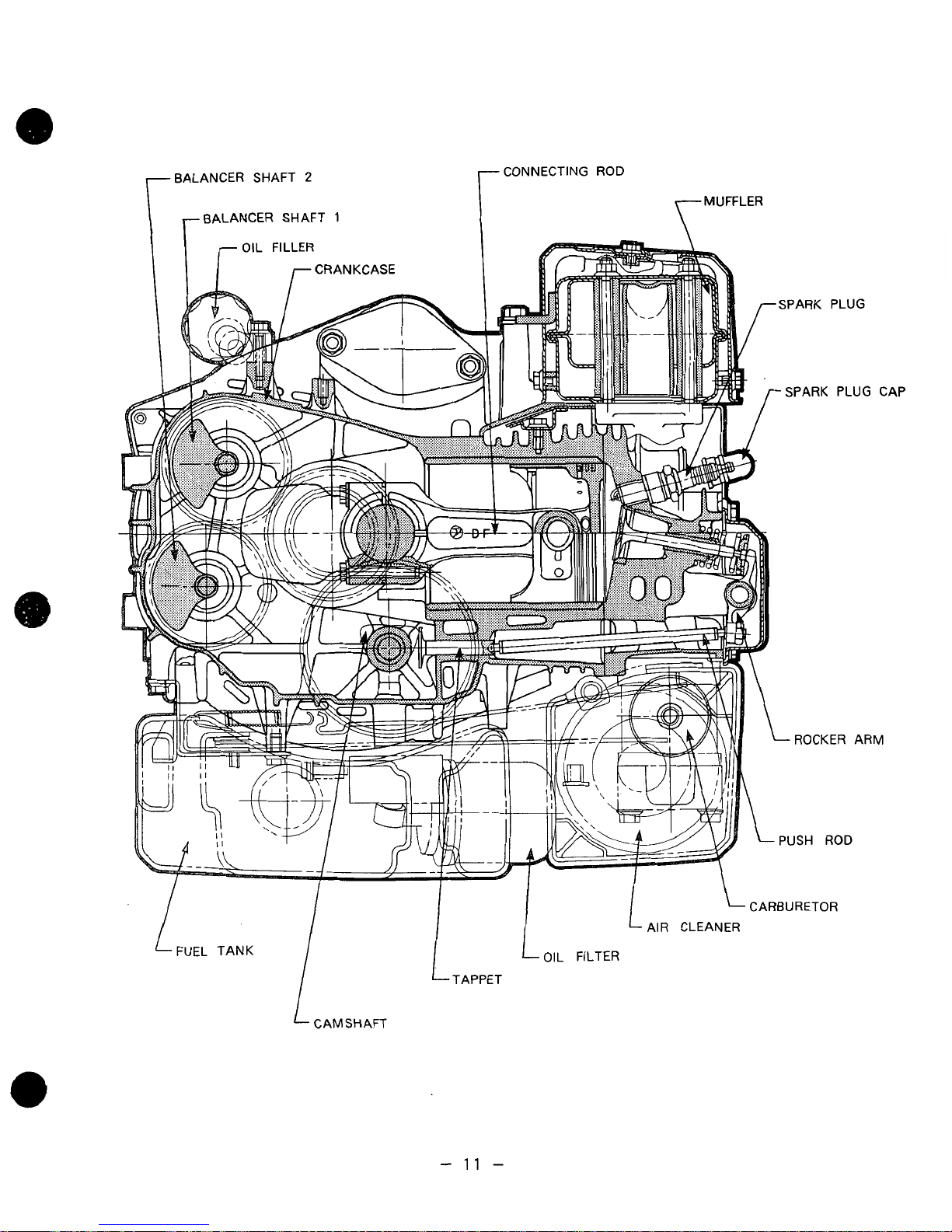
BALANCER SHAFT
2
BALANCER SHAFT
1
CONNECTING
ROD
TMUFFLER
CAP
M
CARBURETOR
AIR CLEANER
OIL
FILTER
CAMSHAFT
-
11
-
Page 16
5.
DISASSEMBLY
5-
1
PREPARATIONS AND SUGGESTIONS
1)
When disassembling the engine, memorize well the locations of individual parts
can be reassembed correctly.
be
that tags
2)
Have boxes ready to keep disassembed parts by group.
3)
To
prevent missing and misplacing, temporarily assemble each group of disassembed parts.
4)
Carefully handle disassembed parts, and clean them with washing oil
5)
Use the correct tools in the correct way.
attached to them.
AND
If
REASSEMBLY
yor are uncertain
of
identifying
some
parts,
if
so
it
is suggested
necessary.
that they
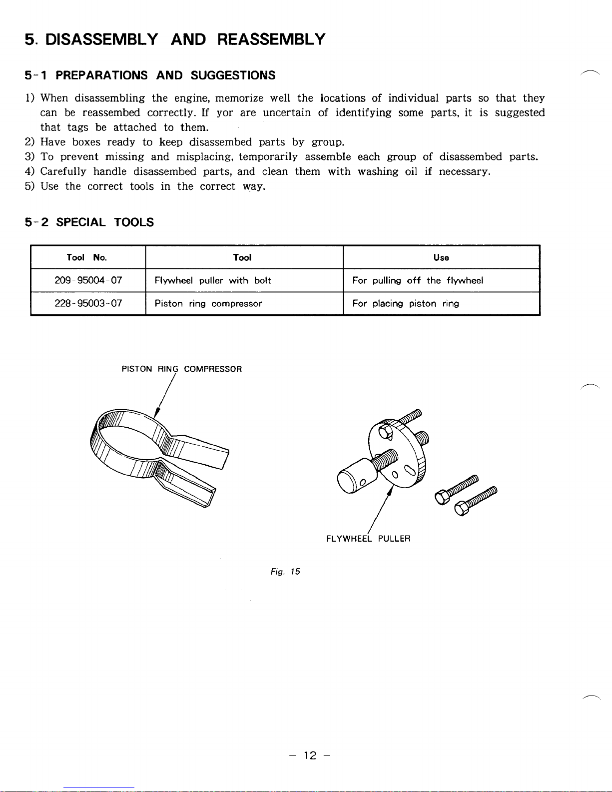
5-2
SPECIAL TOOLS
Tool
No.
209
-
95004
-
07
228 - 95003
-
07
PISTON
Tool
Flywheel puller with
Piston ring compressor
RING
COMPRESSOR
bolt
/
Use
For
pulling off the flywheel
For placing piston ring
Fig.
15
-
FLYWHEEL
12
-
PULLER
Page 17
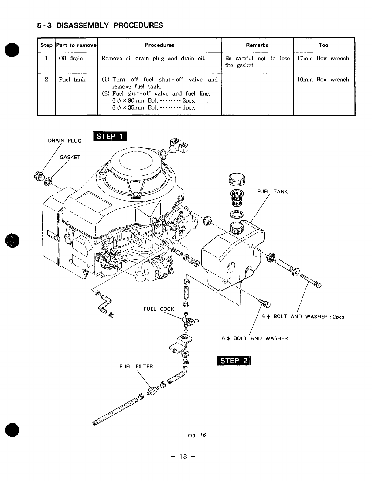
5-
3
DISASSEMBLY PROCEDURES
Part
to remove
Oil
drain
Fuel tank
Procedures
Remove
(1)
(2)
oil
drain plug and drain oil. 17mm
Turn
remove fuel
Fuel shut-off valve and fuel line.
6
6
off fuel shut - off valve
tank.
d
X
~OITUII
4
X
35m
Bolt
*.**--**
Bolt
*-.-..*.
2pcs.
1
pce.
and
Remarks
Be
careful not to
the gasket.
lose
lOmm
Tool
Box
Box
wrench
wrench
BOLT
I
AND
WASHER
6
+
Fig.
I6
-
13
-
Page 18

Step
3
Part
to
remova Procedures
Air cleaner
(1)
Remove air cleaner cover and element.
6
d
Plastic nut
6
d
Wing
nut
(2)
Remove
6
d
6
d
(3)
Remove breather hose from cleaner
base
(4)
Remove cleaner
cleaner) from stud
6
air
X
2Omm
x
lOmm
and
Nut
--**
cleaner bracket
Bolt
.--.
Bolt
*.-e
crankcase.
base
bolts.
2pcs.
lpce.
lpce.
and gasket
(Air
Remarks Tool
lOmm
lOmm
Box
Box
wrench
wrench
6
Q
FLANGE NUT:
2pcs.
6
Q
CLEANER
FLANGE
COVER
BOLT
Fig.
17
-
14
-
Page 19
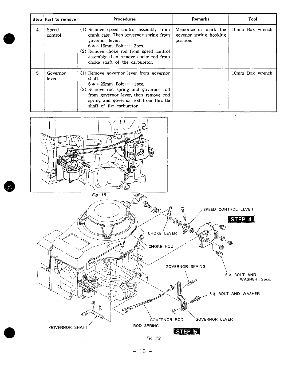
tep
Procedures
Remarks
Tool
4
control
Governor (1) Remove governor lever from governor
lever shaft.
(1) Remove speed control assembly from
case.
crank
governor lever.
q5
X
6
(2) Remove choke rod from speed
assembly, then remove choke rod from
choke shaft of the carburetor.
6
q5
x
(2)
Remove rod spring and governor rod
from governor lever, then remove rod
spring and governor rod from throttle
shaft
Then governor spring from
16mm Bolt
25mm Bolt
of
the carburetor.
-...
*-a.
2pcs.
lpce.
1
control
Memorize
govenor spring hooking
position.
or
mark the
10mm
10mm
Box
Box
wrench
wrench
GOVERNOR
SHAFT
/
ROD
-
SPRING
Fig.
15
Ppcs.
19
-
Page 20
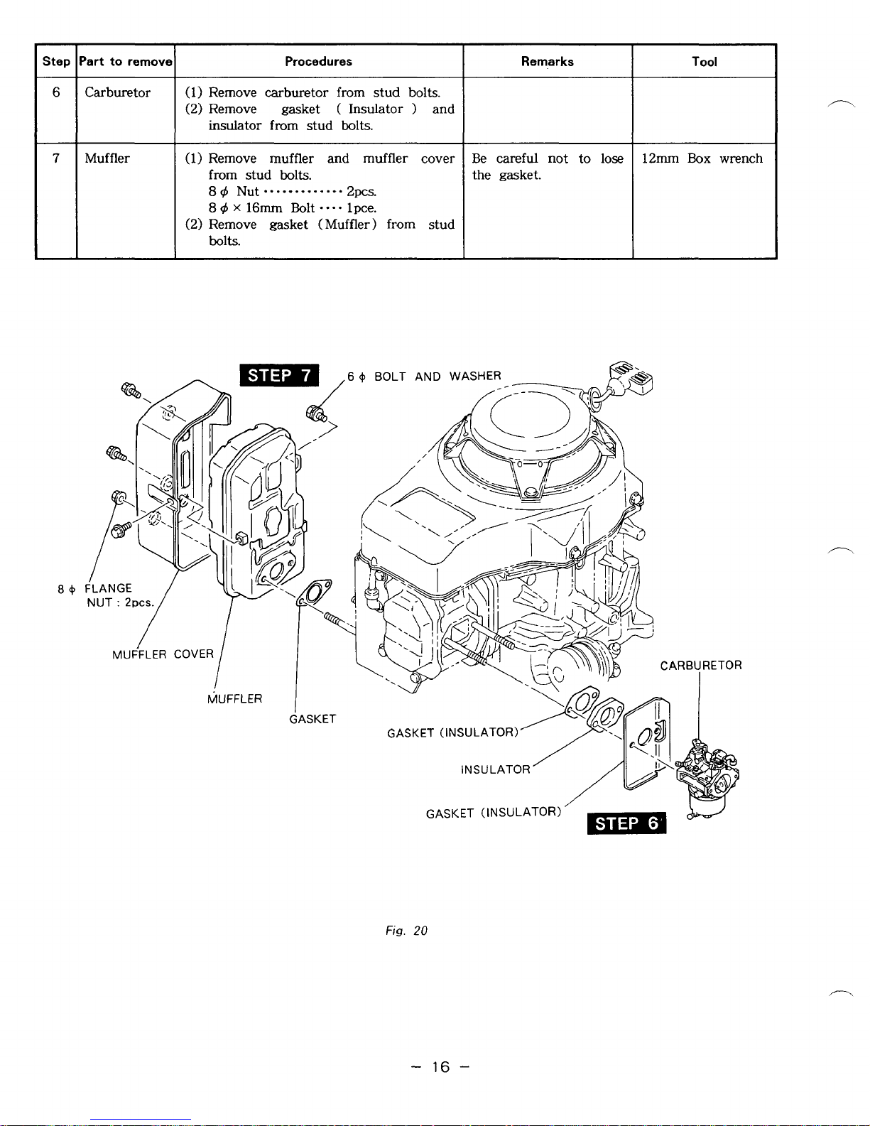
Part to remove
Step
Procedures
Remarks
Tool
6
Carburetor
Muffler
(1)
Remove carburetor from stud bolts.
(2)
Remove gasket
insulator from stud bolts.
(1) Remove muffler and muffler cover
from stud
84
8
4
x
(2)
Remove gasket (Muffler) from stud
bolts.
Nut........
16mm
bolts.
Bolt
(
Insulator ) and
.....
2pcs.
....
lpce.
Be careful not to
the gasket.
lose
12mm Box wrench
Fig.
20
-
16
-
Page 21

Step
'art to remove
-
8
9
-
Electric
starter
(Option)
Diode
rectifler
Procedures
(1)
Remove Black Wire From
Starter.
6
q5
Nut
***.*
1
pce.
(2)
Remove electric starter from crank-
case.
8
9
x
30mm Bolt
(1)
Disconnect wires.
GreedWhite
White
(2) Remove diode rectifier and bracket
from crank case.(See Fig. 22.)
6
q5
x
.
. . .
15mm Bolt
*
-
-
. . . . . .
-.--
2pcs.
2
*
1
....
2pcs.
Electric
Remarks
~~
Reattach The terminal
nut to the motor to
keep it from missing.
lOmm
12mm
lOmm
Tool
Box
Box
Box
wrench
wrench
wrench
Fig.
21
-
17
-
Page 22
Step
l~art
to
remove1
Procedures
Remarks
Tool
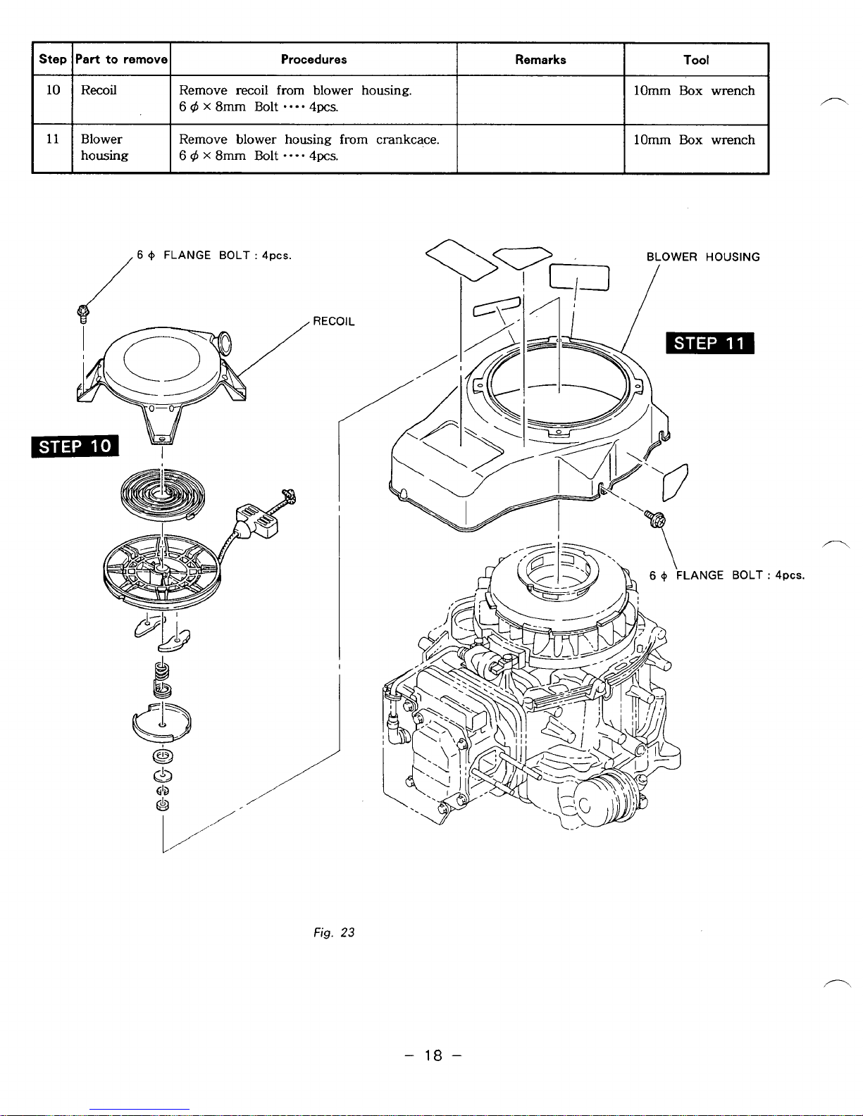
lo
11
I
Blower
housing
/
6
+
FLANGE BOLT
Remove
6
x
8mm
6
d
X
8rn
recoil
from blower housing.
Bolt
*.e-
4pcs.
Bolt
.--.
4pcs.
:
4pcs.
from
crankcace.
lorn
Box wrench
I
l0mm
/
Box wrench Remove blower housing
BLOWER
/
HOUSING
Fig.
23
.ANGE
BOLT
:
4pcs.
-
18
-
Page 23
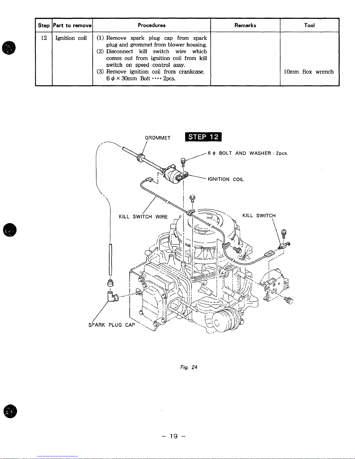
Step
Part
to
remove
Ignition coil
(1)
Remove spark plug
plug
and
(2)
Disconnect kill switch
comes out from ignition coil from kill
switch on speed control
(3)
Remove ignition coil from
6
0
x
Procedures
grommet from blower housing.
30mm
Bolt
I
cap
**-*
2pcs.
GROMMET
from spark
wire
which
assy.
crankcase.
Remarks Tool
6
+
BOLT AND WASHER
IGNITION COIL
:
2pcs.
I
KILL
SWITCH
&$
I
WIRE
Fig.
24
-
19
-
Page 24
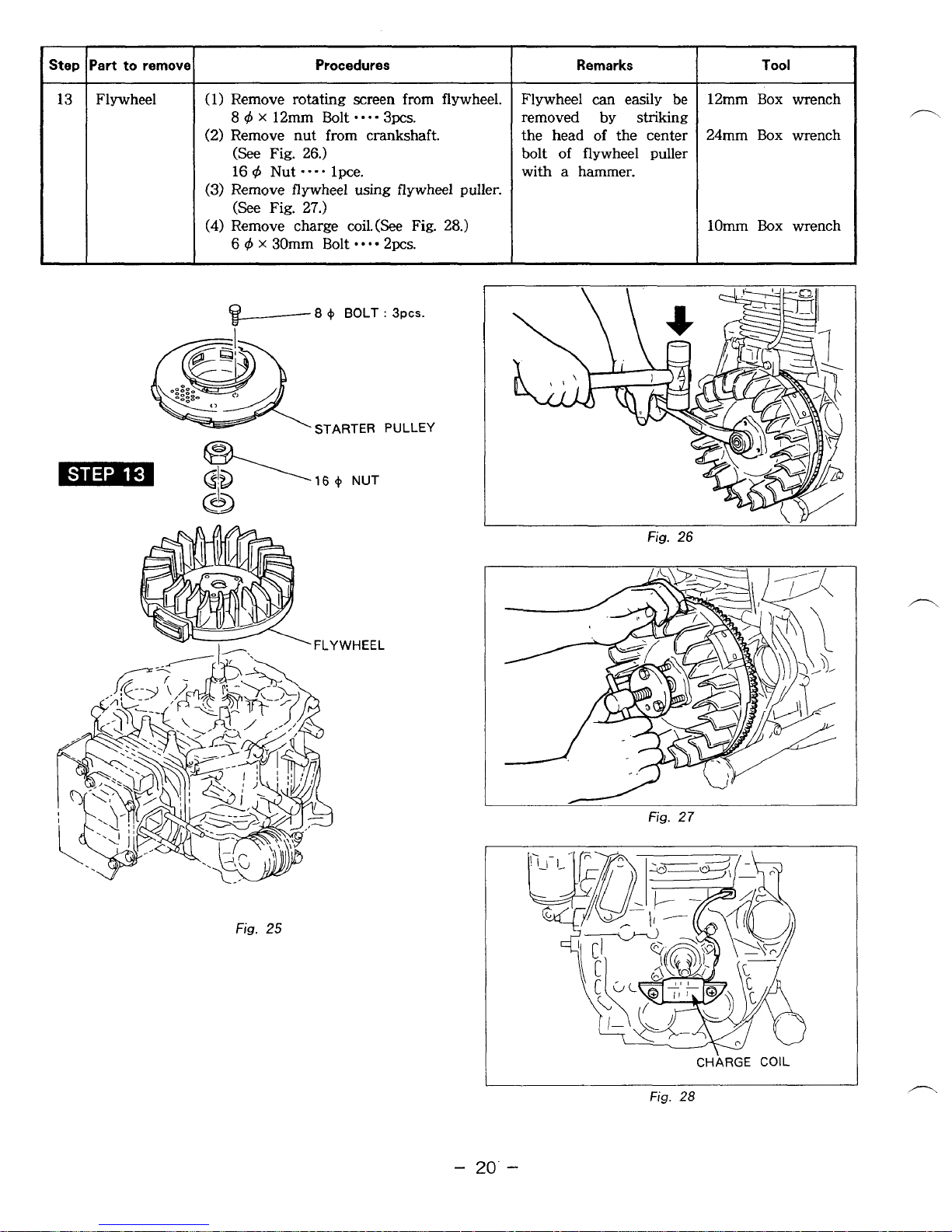
Step
lPart
to
13
I
Flywheel
rem0
(1) Remove
8
X
(2)
Remove nut
(See Fig.
16 4 Nut
(3)
Remove flywheel using flywheel puller.
(See
(4)
Remove charge coil.(See Fig.
6
d
X
Procedures
rotating
12mm Bolt
26.)
---a
Fig. 27.)
30mm Bolt
from
lpce.
screen
.-.-
3pcs.
crankshaft.
*-*=
2pcs.
1
from flywheel.
28.)
Remarks
Flywheel can easily be
removed by striking
of
the head
bolt
of
a
with
the center
flywheel puller
hammer.
12mm
24mm
lOmm
Tool
Box
Box
Box
wrench
wrench
wrench
$-
"
8
+
BOLT
STARTER
'FLYWHEEL
:
BPCS.
PULLEY
1
Fig.
26
Fig.
25
-
I
I
20.
-
fig.
Fig.
27
CHARGE
28
COIL
Page 25

Step
to
remove
Remarks Procedures Part
Tool
14
Cylinder
baffle etc.
(1)
Remove Cylinder Baffle.
6
4
x
8mm Bolt
(2) Remove exhaust manifold and gasket.
8
4
Nut
****
(3)
Remove spark plug.
..-.
2pcs.
4pcs.
lOmm Box wrench
BOX
12mm
19mm Plug wrench
wrench
GASKET
EXHAUST MANIFOLD
T
%
Fig.
29
-
21
-
8
+
FLANGE
NUT
:
PPCS.
Page 26

Part to remov
Procedures
Remarks
Tool
Cylinder
head
(1)
Remove rocker cover and gasket.
6
4
x
12mm Bolt
(2) Loosen lock nut for rocker arm
adjusting screw.
8
cJ5
Nut
---a
(3)
Slide off rocker arm shaft
holder to the flywheel side, remove
rocker arms.
(4) Remove
(5)
Remove cylinder head and gasket.
10
cJ5
X
push
75mm Bolt
e.-
-
4pcs.
2~~s.
rods.(See
-
-
Fig.
4pcs.
from
31.)
the
Mark rocker arms and
push
rods
so
they be
reinstalled in their
original positions.
lOmm ' Box
12mm
14mm
Box
Box
wrench
wrench
wrench
6
+
FLANGE
BOLT
:
Fig.
30
I\
I'
ADJUSTING
8
4
ROCKER ARM
NUT
:
2pcs.
SCREW
Fig.
31
-
22
-
Page 27

Step
16
17
-
Part to remov
Intake and
exhaust
valve
Breather
Procedures Remarks
(1)
Press -down spring retainer and slide Clean carbon and gum
it to release
from
the groove
of
valve deposits from the valves,
stem, then remove spring retainer and
valve
seats,
ports and
valve spring.(See Fig.
32.)
guides. Inspect valves,
(2)
Remove intake and exhaust valves valve seats and guides.
from
cylinder head.
(1)
Remove breather cover.
6
4
x
12mm Bolt
.-e-
2pcs.
Remove gasket
(
breather cover
)
,
breather plate and gasket (breather
plate).
Tool
lOmm
Box
wrench
6
+
FLANGE BOLT
:
2pcs.
9
BREATHER COVER
e
GASKET (BREATHER COVER)
BREATHER PLATE
GASKET (BREATHER PLATE)
Fig.
32
INTAKE VALVE
VALVE SPRING
EXHAUST VALVE
SPRING RETAINER
VALVE GUIDE
OIL SEAL
Fig.
33
-
23
-
Page 28

18
Oil filler
Oil filter
Procedures
(1)
Remove
and pull
bearing
(2)
Remove oil filter from oil filter
bracket using oil filter tool.
(3)
Remove oil filter bracket from main
bearing cover.
8
6
cover.
X
45mm Bolt
4
X
30mm
out
bolt
oil filler from main
--e-
2pcs.
on
oil filler
I
Be
careful
O-ring
of oil filler.
Remarks
not
on
the bottom
to loose
~~
I
lOmm
~
I
12mm
Tool
Box
Box
wrench
wrench
OIL
FILTER
Fig.
-
’
34
24
BOLT
:
2pcs.
-
Page 29

Step
19
20
-
I
'art to remove1 Procedures
I
Remarks
I
Tool
Main
bearing
cover
(1) Remove keys from crankshaft prior to
removal of main bearing cover.
(See
Fig.
36.)
(2)
Remove main bearing cover.
(See
Fig. 37.)
8
q5 X 45mm Bolt
.-.-
7pcs.
Use
a soft hammer and
evenly tap around outer
surface of cover.
Avoid damage to
oil
seal from crankshaft
key
way.
Do
not loose crankshaft
and camshaft spacer.
12mm
Box
wrench
Oil pump
(1) Remove oil filter (Screen) from main
bearing cover.
6
4
x
12mm Bolt
---e
lpce.
6
q5
x
25mm
Bolt
-*-.
3pcs.
(Outer).
(2)
Remove holder (Camshaft).
(3)
Remove
oil
pump (Inner) and
oil
pump
10mm Box wrench
1Omm
Box wrench
6
+
FLANGE BOL
6
+
FLANGE BOLT : 3pcs.
HOLDER (CAMSHAFT)
OIL
PUMP
(INNER) MAIN BEARING
COVER
v
h8
+
FLANGE
BOLT
:
7pcs.
fig.
35
Fig.
36
Fig.
37
-
25
-
Page 30

Step
Part to remove
-
21
Balancer
-
Camshaft
22
and tappets
Procedures
(1
1
Position piston at top dead center and
1
remove balancer
(1)
Remove camshaft
(See
Fig.
(2)
Remove tappets
40.)
and balancer
from
crankcase.,
from
crankcase.
2.
Remarks
To
prevent the
from getting
tappets
damages,
put the crankcase
cylinder side down.
(See
Fig.
40.)
Tappet
in their
must
be
original
installed
position.
Mark tappets prior to
removal
to
prevent error.
Tool
fig.
39
Fig.
38
-
26
CAMSHAFT
Fig.
40
-
Page 31

-
Part to remove Procedures
Step
-
23
24
Connecting
and
piston
Crankshaft
(1)
Remove connecting rod bolts and con
-necting rod cap. rod
8
q5
x
46mm
(2)
Turn crankshaft until piston
dead center, push out connecting rod
and piston assembly through top
cylinder.
(3)
Remove clips and piston pin to
remove connecting rod from piston.
(4)
Remove piston rings from piston.
(1)
Tap lightly on flywheel end
crankshaft to rmove from crankcase.
(See Fig.
-
42.)
Bolt
2pcs.
is
at top
Remarks
Scrape
deposits that might
interfere with removal
of
end of cylinder.
of
of
off
all
piston from upper
carbon
12mm
Ring
Tool
Box wrench
expander
Fig.
42
PISTON RING
CRANKSHAFT^'
1
U
SPACER
”---@
Fig.
\
I
I
CONNECTING
41
\
8
+
BOLT
ROD
:
2pcs
CAP
-
27
-
Page 32

5-
4
REASSEMBLY
0
PRECAUTIONS FOR REASSEMBLY
1)
Clean parts throughly before reassembly.
PROCEDURES
Pay most attention to cleanliness of piston, cylinder, crankshaft, connecting rod and bearings.
2) Scrape off all carbon deposits from cylinder head, piston top and piston ring
3)
Check lip of
oil
seals. Replace oil seal if the lip is damaged.
grooves.
Apply oil to the lip before reassembly.
4)
Replace all the gaskets with new ones.
5)
Replace keys, pins, bolts, nuts, etc.,
6)
Torque bolts and nuts to specification refering to the
7)
Apply
8)
Check and adjust clearances and end
oil to rotating and sliding portions.
if
necessary.
plays
“Table
of.
tightening
where specified in this manual.
torque”.
5-4-1
(1)
CRANKSHAFT
Install crankshaft on crankcase using an oil
seal guide to avoid damage to crankshaft
oil seal. (See
(2)
Install woodruff key for the flywheel on
Fig.
43.)
crankshaft.
-
28
-
Page 33

5-4-2
PISTON AND
PISTON
RINGS
(1)
Install oil ring first, then second ring and top ring. Spread ring only
far
enough to
slip
over
piston and into correct groove. Use care not to distort
ring.(See
Fig.
45.)
Install all the rings with punched mark beside the gap
on
the top side.(See
Fig,.
46.)
e
TOP
RING
SECOND RING
OIL
RING
OPEN ENDS OF PISTON RING
I
Fig.
44
Fig.
45
5-4-3
PISTON
AND
CNNECTING
ROD
When installing piston
on
connection rod, match
the mark
"DF"
on
the
piston with the mark
''@DF"
on connecting rod.(See Fig.
47.)
Oil the small end of connection
rod
before
installing piston and piston pin.
Use
clips
on
both
side of the piston pin to
secure piston pin
in
position.
"N"
MARK
Fig.
46
Fig.
47
-
29
-
Page 34

5-4-4
CONNECTING
ROD
(1)
Before installing the piston and connecting
rod in the cylinder, oil the piston, piston
rings and cylinder
wall.
(2)
Stagger the piston ring gaps
90
’
apart
around the piston.
(See
Fig.
48.)
Use a piston ring compressor when
installing piston.
Install piston and rod
with
the
*
@DF”
marks on flywheel side
of
the crankcase.
(See
Fig.
49.)
(3)
Turn crankshaft to bottom dead center, then
tap
lightly top of the piston until large end
of the
rod
meet crankpin.
(4)
Install connecting rod cap with the match
mark
on
the main bearing cover side.
(Match this mark with the
one
on the left
side
of
connecting rod’s large end viewed
from main bearing cover side.)
(See Fig.
50)
-[NOTES]
(1)
Torque connecting
rod
bolts
to specifi
-
cation.
Tightening Torque
:
225-275kg - cm
by
turning crankshaft
slowly.
(2)
Check
for
free rnovemont
of
connecting
rod
I
-SECOND
RING
RING
.‘
*
TOP
RING
I
Fig.
48
I
PISTON
RING COMPRESSOR
~~ ~~
CONNECTING
I
Fig.
49
I
Fig.
50
-
30
-
Page 35

5-4-5
BALANCER SHAFT
Position piston at top dead center and install
balancer
1
and balancer
2..
Align timing marks on the each gear.
First align timing marks on crankgear and
balancer
1.
Then align timing marks
on
balancer
1
and
balancer 2. (See Fig.
51.)
Incorrect timing
of
the gears will cause
engine’s malfunction and breakage due to
interference
of
the parts.
Fig.
51
5-4-6
TAPPET
AND
CAMSHAFT
(1)
Oil tappets and install in their original
position.
Push in
fully
to avoid damage during
camshaft installation.
(2)
Lubricate bearing surfaces
of
camshaft.
Align timing mark
on
crankshaft gear with
timing mark on camshaft and install
camshaft in the crankcase. (See
Fig.
52.)
Incorrect valve timing will cause engine’s
malfunction.
Fig.
52
-
31
-
Page 36

5-4-7
ADJUST CRANKSHAFT AND CAMSHAFT END
PLAY
Measure end play with the engine cold.(See
Fig.
53.)
End play
is
regulated
by
a selected thickness of adjusting shim located on the crankshaft and
camshaft.
Replacement
is
seldom needed unless the crankshaft, camshaft or main bearing cover have been
replaced.
n
@-ti"
MAIN BEARING
COVER
BALANCER
GEAR
Fig.
53
-
32
-
Page 37

e
(1) Tap end of crankshaft slightly to shoulder shaft against main bearing at flywheel end.
(2)
Use a depth gauge and straight edge to measure the distance between the machined surface
(A)
of the crankcase
(3) Measure the distance between the machined face of the main bearing cover
surface of the main bearing’s inner race
of boss for the plane metal bearing. Record this
(4) The compressed thickness
dimension
(5)
Subtract dimension 1 from dimension
final dimension. Choose an adjusting shim that is 0-0.2mm (0-0.008in.) less than the final
dimension.
(6)
Tap end of camshaft slightly to shoulder shaft against bearing in crankcase.
(7)
Use a depth gauge and straight edge to measure the distance between the machined surface
of the crankcase
(8)
Measure the distance between the machined face of the main bearing cover
surface of the cam bearing thrust
(9)
Use the crankcase cover gasket dimension recorded earlier as dimension
(10) Subtract dimension 4 from dimension
dimension. Choose an adjusting shim that is 0.13-0.29mm (0.005-0.011in.) less than the finafl
dimension for
Choose an adjusting shim that
for EH43V.
3.
EH30V
and the crankshaft gear surface
of
the crankcase cover gasket
(A)
and the camshaft thrust surface
(F).
and EH34V.
is
0.13-0.39mm (0.005-0.015in.l less than the final dimension
(D)
(EH30V
2
and then add dimension
Record this as dimension
5.
Add dimension
(B).
Record this as measurement 1.
and EH34V).
as
dimension 2.
is
0.26mm (0.Olin.). Record this
(E).
Record this
3.
(C)
and the outer
For
EH43V, use outer surface
3.
The result will be the
as
measurement 4.
(C)
and the outer
5.
3.
The result will be the final
as
Crankshaft and camshaft end play
I
I
Crankshaft
Camshaft
Thickness
Crankshaft Shim
Camshaft Shim
of
I
EH30V, EH34V
1
adjusting
EH30V, EH34V EH43V
0.6,
0-0.2
0.1
3-0.29
shims
0.6,
0.8,
0.8
1.0
(rnm)
(mm)
I
EH43V
0.1
1.6.
0.6,
3-0.39
1.8,
0.8
I
2.0
-
33
-
Page 38

5-4-8
(1)
MAIN BEARING
COVER
Install oil pump, holder (Camshaft) and oil
filter (Screen) on main bearing cover.
6
X
Holder (Camshaft)
Tightening Torque
(2)
Lubricate oil seal and bearing surfaces. add
25mm Bolt 3pcs.
:
80-100kg- cm
a light film of oil on main bearing cover
face to hold gasket in place.
Place spacers chosen
crankshaft
and
at
procedure
camshaft.
5-4-7
Use an oil seal guide when installing main
bearing cover to avoid damaging seal.
Align slot in oil pump rotor shaft with oil
pump drive pin in end of camshaft.
(See
Fig.
55.)
Tap cover into place with a soft hammar.
Main bearing cover
8
4
X
45mm Bolt 7pcs.
Tightening Torque
:
170- 190kg- cm
on
1
OIL
PUMP
HOLDER
.
OIL
\
Fig.
54
FILTER
/
I
Fig.
55
5-4-9
OIL
FILLER AND
OIL
FILTER
Install oil filler and gauge, oil filter and oil filter bracket on main bearing cover.
Oil filter bracket
Tightening Torque
5-4-10
BREATHER
8
@
X
45mm Bolt 2pcs.
:
170- 190kg- cm
Install gasket (Breather plate, Brown), breather plate, gasket (Breather cover, Green) and breather
cover.
6
@
X
Breather cover
12mm Bolt
a-
2pcs.
-
34
-
Page 39

5-4-11
(1)
(2)
(3)
(4)
INTAKE AND EXHAUST VALVE
Clean carbon and gum deposits from the valves, seats, ports and guides. Inspect valves, valve
seats and valve guides..
Replace valves that are badly burned, pitted or warped.
When installing valves in cylinder head. Oil valve stems and insert them into valve guide.
Then place cylinder head on flat table, install washer, valve spring and spring retainer.
Valve guides should be replaced when valve
1"
"
for
stem clearance exceeds specifications (See
SERVICE
press
clearance specifications and proper assembly.
After replacing valves and valve guides, lap
valves in place until a uniform ring shows
around the face
and wash cylinder head thoroughly.
DATA").
new
guides in. Refer to "Table
Draw valve guides out and
of
the valve. Clean valves,
VALVE
A-Valve Face Angle
B-Seat Angle
C-Guide Inside Dia.
D-Valve Stem Outside Dia.
Clearance Between
AND
VALVE
C
And D
GUIDE
CLEARANCE
Intake
Exhuast
I
Intake
I
Exhuast
Table
t
45
45
6.600 - 6.622
6.535
-
6.522
-
0.050
-
0.056
-
7
mm
6.550
mm
6.544 mm
0.087
mrn
0.100mrn
-
35
-
Page 40

5-4-12
(1)
CYLINDER HEAD
Clean carbon from combustion chamber and dirt from between the cooling fins. Check the
cylinder head mounting face for distortion.
SERVISE DATA”
1,
replace head.
If
distortion is greater than specification (See
(2) In reassembly use new cylinder head gasket.
(NOTES]
”
not install spark plug at this time. This will ease in
Do
assembly. When installing spark
Cylinder Head 10
4
X
Tightening Torque
Spark Plug Tightening Torque
75mm
plug,
torque to specification (See
Bolt
-0.
4pcs.
:
340--42089- cm
:
New Spark Pulg 120-150kg- cm
Retightening 230-270kg- cm
5-4-
13
ROCKER ARMS AND
(1)
Install push rods in cylinder, make sure that
is
each rod
secured
in
PUSH
RODS
the depression on the
tappet.
(2) Install rocker arm shaft on the cylinder
head from flywheel side.
Install rocker arms and spacer.
(3)
Position piston at top dead center and
adjust tappet clearance.
-[NOTES]
Tappet clearance must be measured with
engine cold.
:
Tappet clearance
Tighten adjusting nuts firmly.
Check operation of values
shaft.
Remeasure tappet clearance.
0.085-0.1
15mm
by
turning crank-
turning
engine over for remainder
“SPECIFICATIONS”).
Fig.
56
of
(4) Install rocker cover and gasket.
6
4
X
Rocker cover
12mm Bolt 4pcs.
Fig.
5
7
-
36
-
Page 41

5-4-14
(1)
L
I
(2)
(3)
CYLINDER
BAFFLE
Install spark plug
Install exhaust manifold and gasket.
Exhaust manifold
Install cylinder baffle
Cylinder baffle
6
8
4
4
X
8mm Bolt
etc.
Nut
****
2pcs.
*-*
4pcs.
5-4-15
(1)
(2)
5-
4-
(1)
CHARGE
COIL
Install charge coil on crankcase.
Charge coil
Clamp wires
Clamp
I6
6
FLYWHEEL
on
4
X
lOmm Bolt
20mm Bolt
crankcase.
*--
*
0-
1 pce.
2pcs.
6.4
X
Clean dust and oil from tapered portion of crankshaft and flywheel.
Install flywheel on crankshaft and torque nut to specifications.
Flywheel
(2)
Install rotating screen on flywheel.
Rotating screen
5-
4-
17
IGNITION COIL
(1)
Install ignition coil
Adjust flywheel magnet
16 4 Nut
-
lpce.
Tightening Torque
8
4
X
12mm Bolt
on
crankcase.
to
ignition coil air
:
850-950kg- cm
-*-
3pcs.
gap to specification, then tighten mounting
bolts.
Coil clearance
Ignition Coil
(2)
Connect spark plug cable
(See
Fig.
:
6
58.)
0.3-0.5
q5
X
30mmBolt
mm
*
to
spark plug.
2pcs.
5-4-
18
6
q5
5-
4-
4
6
4
5-4-20
BLOWER
x
8mm Bolt
9
RECOIL STARTER
x
8mm Bolt 4pcs.
DIODE
HOUSING
*
4pcs.
RECTIFIER
Install diode rectifier and bracket
Bracket, diode rectifier
6
@
X
Connect wires as shown on the wiring diagram.
(See Section
6 - 3.)
on
crankcase.
12mm Bolt
Fig.
58
*
2pcs.
-
37
-
Page 42

5-4-21 ELECTRIC STARTER
8
4
X
30mm Bolt
*-e*
2 pcs.
Connect wires as shown on the wiring diagram. (See Section
6
-
3.)
5-4-22 MUFFLER
Replace gasket and install muffler on cylinder head.
Maffler
8
Nut
*--*
2pcs.
Tightening Torgue
:
180--220kg- cm
8
q5
X
16mm Bolt
****
1
pce.
5-4-23 CARBURATOR,
LINKS
AND
AIR
CLEANER
(1)
Install insulator and heat deflector on studs.
Connect governor rod and rod spring to
throttle shaft of carburetor, choke rod to
choke shaft
of
carburetor. Then install
carburetor on studs. (See
Fig.
59.)
Fig.
59
(2)
Install gasket, air cleaner on studs.
EH30V, 34V
:
Install gasket with lips for air vent groove toward air cleaner.
CARBURETOR
SIDE
EH43V
:
Install as shown below.
Fig.
60
AIR CLEANER
SIDE
”-.
CARBURETOR
SIDE
AIR
CLEANER
SIDE
Fig.
61
-
38
-
Page 43

5-4-24
AIR
CLEANER
Install cleaner base on studs, install bracket, cleaner.
Tighten the clamp for stop switch wire together with cleaner bracket
on
crankcase side.
Tightening Torque
:
EH30V,
34V
70-90kg- cm
Cleaner Base
6
4
Nut
*-*-
2pcs.
EH43V
Bracket Cleaner
6
q5
X
20mm Bolt
0-
lpce.
6
q5
X
lOmm Bolt
***-
lpce.
5-4-25
GOVERNOR
ADSUSTMENT
For
correct carburetor throttle opening and
governor regulation, the govenor lever must be
properly adjusted.
(1)
Install throttle lever control linkage on
governor lever and choke shaft control rod
in choke lever.
(2)
Hook spring
from
control bracket hole
(A)
to the hole (1,
2,
3)
in governor lever as
shown in Fig.
62.
Install bracket assembly
on
crankcase.
(3)
Install governor lever on governor shaft but
do
not tighten clamp screw.
(4)
Turn governor lever clockwise until throttle
valve in carburetor is opened fully. Hold
lever in this position.
IMPORTANT
:
Check
that
governor lever
damp
screw
is
loose
so
governor shaft can
be
turned independently
of
lever.
(5)
Insert a screwdriver in slot at end of
governor shaft. Turn clockwise
as
far as
shaft can be turned. Tighten governor lever
clamp screw.
1
10- 130kg- cm
EH43V
(3)
-
(A)
Fig.
62
I
Fig.
63
-
39
-
Page 44

5-4-26
FUEL
TANK
Install fuel tank, connect fuel lines and clamp them.
Fuel Tank
6
@
X
90mm Bolt 2pcs.
6
@
X
35mm Bolt
*--*
lpce.
5-4-27
ENGINE
OIL
After complete reassembly, turn the engine over using recoil starter to check
for
any abnomal
conditions or loose fitting parts.
Review and check wiring.
Fill crankcase with correct grade
of
oil.
Crankcase oil capacity
EH30V,
EH34V
:
1
lOOcc
EH43V
:
1300cc
5-4-28
CHOKE AND SPEED ADJUSTMNT
Operate the engine without load. Without moving the choke lever, turn speed contrc
choke lever until it just contacts the choke lever adjusting screw.
Use a tachometer
or
revolution counter to regulate the choke start position and high speed operating
revolution. Turn the adjusting screw in or out against the speed control lever until the desired
no
load
operating speed is obtained. This same position will be the start
of
the choke operation.
(See Fig.
64.)
GOVERNOR LEVER
CHOKE LEVER
GOVERNOR SPRING
ADJUSTING
SCREW
)1
lever toward
SPEED CONTROL LEVER
fig.
64
-
40
-
Page 45

5-4-29
An engine that
TEST
REBUILT
has
ENGINE
been completely overhauled
by having the cylinder rebored and fitted with
a new piston, rings, valves and connecting rod
should be thoroughly
RUN-IN
before being put
back into service. Good bearing surfaces and
running clearances between the various parts
can only be established by operating the
engine under reduced speed and loads for
short period
While the engine
of
time.
is
being tested check
for
leaks.
Make final carburetor adjustment and regulate
the
engine
I
operating speed. (See
Step
3
Step
4
Step
5
3.5
7.0
ps
ps
Fig.
65.)
No
4.0
8.0
load
ps
ps
a
oil
Table
Fig.
65
10
30
60
min.
min.
min.
I
3,600
5.0
ps
10.0
ps
2
3,600
3,600
-
41
-
Page 46

6.
MAGNETO
6-
1
Flywheel
Magneto
The ignition system
of
the
EH30/EH34.
and
EH43
is pointless flywheel magneto with automatic
advancing characteristic.
Being different from the breaker point
type
ignition system, this system
is
completely free from
such troubles as starting-up failure owing to dirty, burnt
or
corroded point surface. The electronic
automatic advancing ensures extremely easy starts and stable high performance at operating speed
by
advancing the ignition timing to the most suitable point.
6-2
BASIC THEORY
(1)
Revolution of the flywheel generates electricity on the primary side of the ignition coil, and
the base current
I1
flows to the power transistor.
Current
I1
turns the power transistor
"ON"
and the electric current
Iz
flows.
Resister
Ignition Coil
Fig.
66
(2)
At lower engine revolution, when the flywheel reached the ignition point the low speed ignition
timing controll circuit operates to run the base current
I3
to turn the signal transistor
A
"ON"
allowing the current
I1
to bypass as current
14.
At this moment the power trausistor turns
"OFF"
and the current
I2
is
abruptoy shut resulting
in the high voltage generated in the secondary coil which produces sparks
at
the spark plug.
(3)
At higher engine revolution, the advancing controll circuit operates
at
the ignition timing to
run the base current
15
to turn the signal transistor
B
"ON
allowing the current
I1
to bypass
as current
Is.
At
this moment the power transistor turns
"OFF"
and the current
Iz
is
abruptly shut resulting
in the high voltage generated in the secondary coil which produces sparks at the spark plug.
The operating timing
of
the advancing controll circuit advances in accordance with the increase
of
engine speed resulting in the advancing
of
ignition timing as shown in
Fig.
66.
-
42
-
Page 47

KEY
SWITCH TYPE
12VOLT
BATTERY
MINIMUM
24AMP.HR.
I
I
-
DIODE
RECTIFIER
I
""""""""_
I
STARTER
SWITCH
AND
STOP SWITCH TYPE
~ ~~ ~~ ~ ~~
E
0
DIODE
RECTIFIER
U
I
I
-
!"_"""""""I
L
12VOLT
BATTERY
MINIMUM
24AMP.HR.
Fig.
67
r
[NOTE]
The parts and wiring outside
of
the dotted line are to be prepared
by
the original equipment
manufacturer.
-
43
-
Page 48

7.
AUTOMATIC
DECOMPRESSION
SYSTEM
The decompression system operates to release compression
by
lifting up the exhaust valve
at
n
starting.
The release lever mounted on the camshaft has a flyweight at one end and
a
crescent cam at
the other end. When starting the engine, the crescent cam juts out from the exhaust cam.
The exhaust tappet rides over the crescent cam opening the exhaust valve to release compression.
LEVER
CRESCENT
EXHAUST
Fig.
68
When the crank speed reaches
a
certain revolution, the flyweight
of
the release lever moves outward
by
the centrifugal force turning the release lever to retract the crescent cam.
Thus
the exhaust
valve closes allowing
a
sufficient compression for the engine to start up.
/1
CRESCENT
CAM
EXHAUST
CAM
Fig.
69
LEVER
-
44
-
Page 49

8-4
8-
The float chamber is located just below the carburetor body and, with
maintains
OPERAUUON
4
-
I
FLOAT
a
AND
SYSTEM
CONSTRUCTION
(See
Fig.
constant fuel level during engine operation.
69.
and
40.)
a
float and
a
needle valve,
The fuel flows from the fuel tank into the float chamber through needle valve. When the fuel
rises to
a
specific level, the float rises
;
and when its buoyancy and fuel pressure are balanced,
the needle valve closes to shut off the fuel, thereby keeping the fuel at the predetermined level.
I
BYPASS
JET
PILOT
THROTTLE VALVE
PILOT OUTLET
VALVE
I
r*
I
\L-
"i"""-
PILOT
c
AIR
JET
Fig.
"_
JI
WELL
-"IF
BODY
4
70
FLOAT
NEEDLE
Fig.
71
-
45
-
VALVE
Page 50

8-1-2
PlLOT SYSTEM
The pilot system feeds the fuel to the engine during idling and low- speed operation.
The fuel
is
fed through the main jet to the pilot jet, where it
is
metered, and mixed with the
air metered by the pilot air jet.
is
The fuel-air mixture
At
idling speed, the fuel
8-
1-3
MAIN
SYSTEM
fed to the engine through the pilot outlet and the bypass.
is
mainly fed from the pilot outlet.
The main system feeds the fuel to the engine at,’medium-and high-speed operation.
is
The fuel
air
jet is mixed with the fuel through the bleed holes
atomized out of the main bore. It
an optimum fuel-air mixture, which
8-
1
-4
The choke is used for easy start when engine
metered by the main jet and fed to the main nozzle. The air metered by the main
in
the main nozzle, and the mixture
is
CHOKE
mixed again with the
is
supplied to the engine.
is
cold. When the starter is operated with a closed
air
taken through the air cleaner into
choke, the negative pressure applied to the main nozzle increases and draws much fuel accordingly
thus easily start up the engine.
8-
2
DISASSEMBLY AND REASSEMBLY
Apart from mechanical failures, most of carburetor troubles
ratio, which may arise mainly due to a clogged up air
variations. In order to assure proper flow of
air
and fuel, the carburetor must be kept clean
all times. The carburetor disassembly and reassembly procedures are
are
caused by ‘an incorrect mixing
or
fuel passage in jets, or fuel level
as
follows : (See Fig.
71.)
/”.
is
;
at
8-2-1
(1)
(2)
THROTTLE SYSTEM
Remove the philips screw
11,
valve (1
The spring
and pull out the throttle shaft
(17)
can be taken out by removing
the throttle stop screw
(16).
(
10)
and throttle
*Exercise care not to damage throttle valve
ends.
8-2-2
(I)
(2)
CHOKE SYSTEM
Remove the
(131, and pull out the choke shaft
philips
screw
(14)
and choke valve
(31).
When reassembling the choke shaft, make
that the cutout in the choke valve faces. the
main air jet.
Meantime, when reassembling set the rings
(34)
(32) and
8-2-3
PILOT SYSTEM
Remove the pilot jet
to avoid damage to
at the right position.
(181,
it.
using correct tool
Reassembly
Tighten the pilot jet securely. Otherwise, the
fuel
may
leak, causing engine malfunction.
(30).
sure
Fig.
28
29
72
-
46
Page 51

8-2-4
(1)
(2)
(3)
MAIN
Remove the
SYSTEM
bolt
From the body
main nozzle
(19).
Reassembly
(29)
and take out float chamber body
(1)
remove the main nozzle
(26).
(19),
and then remove the main jet
(20)
a) Fasten the main jet securely to the body. Otherwise, the fuel may become too rich and
cause engine malfunction.
b) The bolt tightening torque
is
7Okg-cm.
from the
8-2-5
(1)
When cleaning the jets, use neither
orifice which will adversely affect fuel flow).
clean.
(2)
FLOAT
Pull out the float pin
SYSTEM
(36)
and remove the float (27) and needle valve
a
drill nor a wire (because of possible damage of the
Be
sure
to
use compressed air to blow them
When removing the needle valve and floats, gently tap the reverse side using the rod more
slender than the float pin and remove, since the float
pin-is
calked to the carburetor body.
(35).
-
47
-
Page 52

9.
STARTING
SYSTEM
9-
1
RECOIL
STARTER
When repairing recoil starter, disassemble and reassemble in the following procedures.
Tools
:
Socket wrench, Needle nose pliers, Screw driver
9-
1
-
1
DISASSEMBLYH
(1)
Remove recoil starter from engine.
(2)
Pull starter knob and pull out starter rope
for 30-40cm to line up notch on reel with
outlet hole for starter rope.
Hold reel with thumb and pull starter rope
inside starter case with screw driver.
(See Fig.
73.)
Rewind reel clockwise until the rotation
stops.
When rewinding the reel, control the
rotation
by
holding starter rope using the
notch on the reel and pressing the reel with
thumb.
(3)
Remove parts in the following order.
1.
Nut
2.
Spring washer
3.
Thrust washer
4.
Thrust washer
B
5.
Friction plate
6.
Return spring
7.
Friction spring
8.
Ratchet.
Fig.
73
Fig.
74
-
48
-
Page 53

(4)
Remove reel from starter case as shown in
Fig.
75.
Take out reel slowly turning it lightly
toward left and right to remove spring from
the hook.
Do
not remove the reel quickly
or the spring may escape from the starter
If
case.
starter case as instructed
the spring escapes, put it in the
in
9-
1
Untie starter rope from the knob and
remove.
9-
1
-2
REASSEMBLY
(1)
Put
starter rope through starter knob and
tie
it
as shown in
Fig.
76.
(Tie the rope
tightly for the safety sake,)
Put
the opposite side
starter case and reel. Tie
of
the rope through
it
in the same way
as starter knob end and put the knot
reel
complely.
(2)
Check that spring is securely set in the
starter case.
Adjust the position of inner end
spring
so
it hooks
on
hook
on
securely.
The shape of starter spring inner end canbe
adjusted with plier if necessary.
-
3.
in
of
the reel
the
the
I
REEL
INNER
END
OF
Fig.
Fig.
76
SPRING
75
REEL
/
HOOK
STAR
OUTER
Fig.
-
49
-
77
END
OF
SPRING
Page 54

(3)
Prior
starter rope in reel for
arrowhead direction as shown in
Then let the rope out of reel
on reel. Line up reel
of spring as shown in Fig.
to
installing reel in starter case, wind
1.5
turns in the
Fig.
from
the notch
hook
with inner end
77
and install
reel in starter case.
Hold starter rope as shown in
6
turn reel
Firmly press
pull starting
times in the arrowhead direction,
not
to
allow reverse turn and
knob
to let starter rope out
Fig.78
of starter case.
Return knob slowly to let starter rope
rewind in reel.
(4)
Reassemble parts in reverse order
disassembly.
When installing friction plate, put return
spring into the slit
of
friction plate and
rotate the plate in the arrowhead direction
79
as shown in Fig.
until notch of the plate
lines up with ratchet.
Press friction plate firmly toward reel,
install thrust washers, spring washer and
nut.
78.
and
of
L
Fig.
78
(5)
Test operation of recoil starter to
see
if rope recoils satisfactorily and ratchets project and
retract properly. Mount recoil starter to the engine.
Fig.
79
3TCH
.
-.
-
50
-
Page 55

(6)
If spring escapes from starter case when
disassembling recoil, recoil and assemble in
the following manner.
a) Make
thin wire
the one
a
spring
of
holder
of
which diameter
for
the spring with
is
smaller than
spring housing in starter case
and twist the end together.
Wind the power spring inside the wire ring
of
starting with the outer loop
(See Fig.
b)
Place the spring assembly over the recess
in the housing,
outer loop
in the housing (See
80.)
of
so
that the hook in the
the spring
Fig.
77.)
the spring
is
over the tab
Fig.
80
Carefully press the spring out the wire ring and into the recess in the housing.
(7)
Lubricate the rotating parts, sliding parts and spring with heat resistant grease or mobile
oil
when reassembling recoil and prior to long term storage.
-
51
-
Page 56

9-2
9-
(1)
(2)
(3)
ELECTRIC STARTING
2
-
1
DISASSEMBLY
The 6mm terminal nuts
Remove the
"M"
terminal bush
6mm
The 5mm through bolts
Remove the
"M"
The rear cover
the
5mm
through bolts.
terminal nuts.
No,l
terminal bush
is
disassembled
MOTOR
(2pcs.)
(2pcs.)
(2pcs.)
(2pcs.)
No,
by
removing
(OPTION)
1.
Fig.
81
(4)
The rear cover
Remove the rear cover.
Fig.
82
I
Fig.
-
52
-
83
4
/
3
Page 57

(5)
The 4mm screws (2pcs.I
(6)
The brush holder.
(7)
"M"
terminal bush
No,
2.
The
brush
holde
is
disassembled by
re-
moving the
4
mm screws. (2pcs.I
Remove the
"M"
terminal
bush
No,
2.
(8)
Yoke assembly.
Remove the yoke assembly.
(9)
The pinion stopper clip.
The pinion stopper clip is removed with
a
standard screwdriver while the pinion
stopper
is
pushed toward the
pinion.
6
7
Fig.
84
Fig.
85
Fig.
86
-
53
-
Page 58

(lo)
Pinion stopper.
(1
1)
Pinion return spring.
(
12)
Pinion assembly.
The pinion stopper, pinion return spring
and
the pinion assembly can be dis
assembled once the pinion stopper clip has
been removed.
(13)
Armature.
(14)
Thrust washers
(15)
Front
cover.
The armature, thrust washers
cover and the
(4pcs.)
yoke
(~Pcs.),
assembly can be
disassenbled once the rear cover.
front
12
11
-
Fig.
87
15
\
Fig.
88
-
54
-
Page 59

9
11
\L
8
1
2
7
>
5
01111111)
6
i
3
4
1.
The 6mm terminal nuts (2pcs.)
2.
"M"
terminal bush
3.
The
5mm
4.
The Rear cover
5.
The 4mm screws
6.
The brush holder
7.
"M"
Terminal bush
8.
Yoke assembly
through bolts (2pcs.)
No,l
(2pcs.)
No,
2
Fig.
89
9.
The
pinion
10.
Pinion stopper
1 1.
Pinion return spring
12.
Pinion assembly
13.
Armature
14.
Thrust washers
15.
Front cover
-
55
-
stopper clip
(4pcs.)
Page 60

9-
2-2
INSPECTION
(1
)
ARMATURE
AND
REPAIR
a) Check the diameter of the commutator.
of
If the out side diamaeter
is
tator
replace
I
Standard
below
it.
the minimum limit then
(New)
I
the commu-
Unit
Limit (Used)
:
rnrn
I
30
b)
Continuity test for the armature coil.
a
Use
tester to check for continuity
29
between parallel points on the commutator.
If
There
is
continuity, the armature is still
good.
No
continuity : (Disconnected coil)
Replace the armature.
I
I__
TESTER
Fig.
Fig.
90
91
c) Insulation
Use
test
for the armature coil.
21
tester to check for continuity
between a point on the commutator and
the shaft or the core.
If There is no continuity, the armature
still
good.
Continuity exists : (Short circuited coil)
Replace the armature.
is
-
I
TESTER
r
I
1-1
Fig.
92
56
-
Page 61

d)
Check for Surface Distortion
on
the Armature and the Commutator.
Use
a
dial gauge to measure the distortion
of
the out side surfaces of the armature
core and the commutator.
If it
is
above
the
limit, then repair
or
replace
it.
Unit
:
mm
I
I
Standard
(New)
I
Limit
(Used)
I
I
Armature
I
0.05
(Max.)
I
0.1
(Max.)
I
8
Q
COMMUTATOR
I
Commutator
I
0.05
(Max.)
I
0.1
(Max.)
I
Fig.
93
e) Check the Surface of
the
Commutator.
If
the commutator surface
is
rough, then
please use
No,
500-600
sandpaper to make
it
smooth.
f)
Check the Depth
of
the Insulating Material
from the Commutator Surface.
If
the
depth
of
the insulating material from
the commutator segments
is
less than the
limit, then please repair
it
by
filing it
down.
Unit : mm
I
Standard
(New)
Limit
(Used)
I
I
0.5-0.8
I
0.2
(Min.)
I
fig.
94
INSULATOR
w
0.5-0.8
mm
COMMUTATOR
SEGMENTS
CORRECT
INCORRECT
I
Fig.
95
-
57
-
Page 62

(2)
BRUSH
Measure the length of the brushes and
if
they are under the limit, replace them.
Unit
:
mm
I
Brush
I
Standard
(New) I Limit (Used)
I
1
Positive side
brush
I
1
2.5
191
I
Negative
side
brush
I
1
2.5
191
(3)
BRUSH
HOLDER
a)
Insulation Test for the Brush Holder.
Check for continuity between the brush
holder's top (Positive side) and its base
(Negative side). If there is no continuity
then it is still good.
Continuity Exists
:
(Unsatisfactory
Insulation)
Replace the brush holder.
b)
Inspection of the Brush Springs.
Check the weight of the brush springs.
I
Standard weight (kg)
I
I
1.4-1.8
I
Fig.
96
Fig.
97
I
I
Fig.
98
-
58
-
Page 63

(4)
PINION
CLUTCH
Inspection
of
the pinion clutch.
Rotate the pinion manually. While rotating
it
in
the direction of normal operation,
smoothly reverse the direction
of
rotation
to confirm that
it
locks.
In the event
of
any irregular
'ity, replace it.
Fig.
99
9-
2
-
3
REASSEMBLY
Reassembly
is
in the revrse order
of
disassembly, however please note the following points.
(1)
The Places
to
Apply Grease
:
The sliding surfaces of the pinion and the shaft's spline.
The metals holding the shaft at the
front
and rear covers.
-
59
-
Page 64

10.
TROUBLESHOOTING
The following three conditionts must be fulfilled
1.
The cylinder filled with a proper fuel-air mixture,
2.
Good compression in the cylinder.
3.
Good
spark,
properly timed, to ignite the mixture.
for
satisfactory engine start.
The engine cannot be started unless these three conditions are met. There are also other factors
g.,
which make engine start difficult, e.
at
low
speed, and
a
high back pressure due to
a heavy load on the engine when
a
long exhaust pipe.
The most common causes of engine troubles are given below
1
0-
1
STARTING
10-1
-
1
FUEL
(1)
No
gasoline in the fuel tank
(2)
The carburetor
(3)
Water, dust
(4)
Inferior grade gasoline or poor quality gasoline
fuel-
air
mixture.
(5)
The carburetor needle valve
DIFFICULTIES
SYSTEM
is
not choked sufficiently, especially when the engine
or
gum
;
or the fuel cock closed.
in the gasoline interfering the fuel flow to the carburetor.
is
not vaporized enough to produce the correct
is
heldopen by
dirt
or gum. This trouble can be detected
:
is
it
cold.
is
about to start
the fuel flows out of the carburetor when the engine is idling.(Overflow)
This trouble may
be
remedied, depending on cases, by lightly tapping the float chamber with
the grip of a screwdriver or the like.
(6)
If the carburetor overflows, excessive fuel runs into the cylinder when starting the engine,
to
making the fuel- air mixture too rich
turn the starting pulley
a
few
turns
in
pulg hole into the atmosphere. Keep the carburetor choke open during this operation.
it
spark plug well, screw
into place, and
burn. If this happens, remove the spark plug, and
order to let the rich fuel-air mixture out of the spark
Dry
try
to start again.
/”-
as
Y
the
10-
1-2
COMPRESSION
If
starting difficulties and
SYSTEM
loss
of
power are not due to the fuel system
followings must be checked for possible lack of compression.
(1)
Engine inside is completely dried
(2)
Loose or broken spark plug. This causes
of
cylinder in compression stroke during cranking.
(3)
Damaged head gasket or loose cylinder head.
up
because
a
hissing noise made by mixture gas running out
of
a
long period
A
similar hissing noise is produced during
compression stroke.
(4)
Incorrect valve clearance
If the correct compression
engine and check further
a)
Valve stuck open due to carbon
b)
If
the piston rings are stuck on the piston, remove the piston and connecting rod from
is
not obtained even after remedying the above, disassemble the
as
follows
or
:
gum
on
the valve stem.
the engine. Clean or replace the parts.
of
or
ignition system, the
storage.
-
60
-
Page 65

0)
10-
1
-
3
lGNlTlON
Check the followings for lack
(1) Leads
(2)
Ignition coil damaged and shorted.
(3)
Spark plug cable wet or soaked with oil.
(4)
Spark plug dirty or wet.
(5)
Spark plug electrode gap incorrect.
(6)
Spark plug electrodes are connected
(7)
Incorrect spark timing.
(1)
Incorrect spark plug electrodge gap. Adjust it to anywhere between
(2)
Ignition cable worn and leaking.
(3)
Sparks weak.
(4)
Ignition wire connections loose.
(5)
Water in gasoline.
(6)
Insufficient compression.
of
SYSTEM
of
sparks.
the ignition coil, spark plug or contact breaker disconnected.
or
bridged.
0.7
and
0.8mm.
10-3
ENGINE
STOPS
(1) Fuel tank empty. Water, dirt, gum, etc. in gasoline.
(2)
Vapor lock,
(3)
VaDor lock in the fuel lines or carburetor due to the use of
i.
e., gasoline evaporating in the fuel lines due to overheat around the engine.
too
volatile winter
hot season.
(4)
Air vent hole in the fuel tank cap plugged.
(5)
Bearing parts seized due to lack of oil.
(6)
Magneto or ignition coil faulty.
10-
4
ENGONE
(1)
Crankcase oil level low. Add
(2)
Spark timing incorrect.
(3)
Low grade gasoline
(4)
Cooling
(5)
Cooling air path misdirected causes loss of cooling efficiency.
(6)
Cylinder head cooling fins clogged up with dirt.
(7)
Engine operated in an enclosed space without sufficient cooling air.
(8)
Exhaust gas discharge restricted,
(9)
Engine running on low-octane gaoline detonates due to heavy load at low speed.
OVERHEATS
is
air
circulation restricted.
oil
immediately.
used, or engine
or
carbon deposits in the combustion chamber.
is
overloaded.
gas
in the
-
61
-
Page 66

10-5
ENGINE KNOCKS
(1)
Poor quality gasoline.
(2)
Engine operating under heavy load at
low
speed.
(3)
Carbon
or
lead deposits in the cylinder head.
(4)
Spark timing incorrect.
(5)
Loose connecting
rod
bearing due
to
wear.
(6)
Loose
piston pin due to wear.
(7)
Cuases
of
engine overheat.
10-
6
ENGINE BACKFIRES THROUGH CARBURETOR
(1)
Water
or
dirt in gasoline,
or
low-grade gasoline.
(2) Intake valve stuck.
(3)
Valves overheated,
or
hot carbon particles in the combustion chamber.
(4)
Engine cold.
-
62
-
Page 67

11.
INSTALLATION
Engine life, ease of maintenance and inspection, frequency of checks and repairs, and operating
cost all depend on the way in which the engine
is
installed. Carefully observe the following
instructions for installing the engine.
11 - 1
INSTALLING
When mounting the engine, carefully examine
its
position, the method of connecting it to a machine,
the foundation, and the mehtod of supporting the engine.
When determining
its
mounting position, in particular, make sure that gasoline and oil can easily
be supplied and checked, the spark plug can easily
be
checked, the air cleaner can easily be serviced,
and that the oil can easily be discharged.
11
-
2
VENTJLATION
Fresh air
is
necessary for cooling the engine and burning the fuel.
In
the. case the engine is operated under
a
hood
or
in a small room, temperature rise in the engine
room can cause vapor lock, oil deterioration, increased oil consumption, loss of power, piston seizure,
shorter engine life, etc., making it impossible to operate the engine properly. It
is
necessary,
therefore, to provide
a
duct or baffle
to
guide cooling air to the engine to prevent recirculation
of the hot air used for engine cooling, and temperature rise of the machine.
Keep the engine room temperature below
50°C
even in the hottest period of the year.
11
-3
EXHAUST GAS DISCHARGE
Exhaust
gas
is
noxious. When operating the engine indoors, be sure to discharge the exhaust gas
outdoors. If a long exhaust pipe
is
used in such a case, the internal resistance increases causing
loss
of engine power. Thus pipe inside diameter must be increased in proportion to exhaust pipe
length.
Exhaust
pipe
:
Less than 3m long, pipe inside diameter 30mm,
Less than 5m long, pipe inside diameter 33mm.
11
-4
POWER TRANSMISSION
TO
DRIVEN MACHINES
11
-4-
1
BELT
DRIVE
Take the following notes into consideration.
*
V-belts are preferable to flat belts.
*.The driving shaft of the engine must be parallel to the driven shaft of the machine.
*
The driving pulley of the engine must be in line with the driven pulley of the machine.
*
Install the engine pulley as close to the engine as possible.
*
If possible,
span
the belt horizontally.
*
Disengage the load when starting the engine.
If
no clutch is used, use a belt tension pulley or the like.
11
-4-
2 FLEXIBLE
COUPLING
When using a flexible coupling, runout and misalignment between the driven shaft and engine
shaft must be minimized. Runout and misalignment tolerance are specified by the coupling
manufacturer.
-
63
-
Page 68

12.
SERVICE
DATA
12-1
I
I
CLEARANCE
CYLINDER HEAD
.Valve seat
Valve guide inside dia.
contact
DATA
width
ITEM
AND
LIMITS
IN.
~
EX.
~~~~ ~~~~~
T
EH30V/EH34V/EH43V
0.05
(0.002)
Unit
0.1
(0.004)
2.0
(0.079)
:
mm
(in)
6.600-6.622
(0.260-0.261)
6.75
(0.266)
-
64
-
Page 69

Unit : mm
(in)
ZYLINDER
B
Inside
dia.
ITEM
EH30V
EH34V
~
STD
1
st
reboring
2nd
reboring
STD
1
st
reboring
STD
78.000-78.01
(3.07 1 -3.072)
78.250-78.269
(3.081
-3.082)
78.500-78.51 9
(3.091 -3.092)
84.000-84.022
(3.307-3.308)
84.250-84.272
(3.31 7-3.31 8)
9
Limit
To
be rebred
lifference between max.
3nd
rnin
.
of diameter
,cached
to
0.1
Ditto
Ditto
Ditto
Ditto
when
(0.004).
the
Out
of
rowdiness after
reboring.
Cylindricity after reboring.
EH43V
EH30V
EH34V
EH43V
2nd
reboring
STD
1
st
reboring
2nd
reboring
84.500-84.522
(3.327-3.328)
89.000-89.022
(3.504-3.505)
89.250-89.272
(3.51 4-3.51
89.500-89.522
(3.524-3.525)
0.01 (0.004)
0.0 1 5
(0.0006)
5)
Ditto
Ditto
Ditto
Ditto
Ditto
Ditto
-
65
-
Page 70

Unit
:
rnm
(in)
PISTON
Piston
thrust
size
(At
direction)
I
Ring groove side clearance
I
skirt.
ITEM
in
#
EH30V
EH34V
EH43V
1st
2nd
1st
2nd
1st
2nd
STD
o/s
o/s
STD
o/s
o/s
STD
o/s
o/s
Tor,
STD
77.96-77.98
(3.069-3.070)
78.2
1
-78.23
(3.079-3.080)
78.46-78.48
(3.089-3.390)
83.98-83.98
(3.305-3.006)
84.2
1
-84.23
(3.31 5-3.31 6)
84.46-84.48
(3.325-3.326)
88.96-88.98
(3.502-3.503)
89.21 -89.23
(3.51 2-3.51 3)
89.46-89.48
(3.522-3.523)
0.05-0.09
(0.002-0.0035)
Limit
77.87 (3.066)
78.1 2 (3.076)
78.37 (3.085)
83.87 (3.302)
84.1 2 (3.3
84.37 (3.322)
88.87 (3.499)
89.1 2 (3.509)
89.37 (3.51
1
2)
9)
0
Piston
pin
hole
.m
0
Piston
Clearance between piston and cylinder
at
skirt
pin
outside dia.
area.
2nd
Oil
EH30V
ring
0.03-0.07
(0.001
2-0.0028)
0.01 -0.065
(0.0004-0.0026)
20.995-21.008
(0.8266-0.8271
20.991 -21
(0.8264-0.8268)
0.025-0.064
(0.001
.OOO
0-0.0025)
0.1
5
(0.006)
)
21.035 (0.828
20.960 (0.8251
1
)
)
EH34V
EH43V
-
0.025-0.067
(0.001
66
-
0.25 (0.0098)
0-0.0025)
Page 71

Unit
:
mm
(in)
ITEM
STD
Limit
*.Clearance between piston and piston
pin.
-
0.005-0.01 7
(-
0.0002-0.0007)
0.06
(0.0023)
Piston ring end gap
TOP
2nd
0.2-0.4
(0.0079-0.01 57)
1.5
(0.059
1
)
0.1
-0.3
(0.0004-0.01
18)
Oil
ring
CONNECTING
ROD
Big
end inside dia.
(Metal is fitted)
0"
38.000-38.01 6
(1.496
1
-
1.4967)
38.1
(1.5000)
Clearance between big end
and- crankpin
0.030-0.060
(0.001
2-0.0024)
0.2
(0.0079)
@
Small end inside dia.
21.01 0-21.023
(0.8272-0.8277)
2 1.080
(0.8299)
Clearance between small
end
and piston
pin
0.01
0-0.032
(0.0004-0.001
3)
0.1 2 (0.0047)
Big
end side clearance
"CCIC
0.1
-0.3
(0.0039-0.01 18)
1
.O
(0.0394)
-
67
-
Page 72

Unit
:
mm
(in)
I
CRANKSHAFT
Crankpin outside dia.
Journal dia.
I
RI
Clealance between
journal and main bearing
I
ITEM
R2
I
Flywheel
side
R1
P.T.0
side
R2
Flywheel
side
STD
37.956-37.970
(1.4943-
34.986-34.997
(1.3774-
34.986-34.997
(
1.3774- 1 -3778)
-
1
-4949)
1
-3778)
0.009-0.01
(-
0.00035
-
0.00055)
37.85 (1.4902)
4
Limit
EH43V
STD
37.956-37.970
(1.4943- 1.494)
34.986-34.997
(1.3774- 1.3778)
34.984-35.000
(1.3773- 1.3780)
-
0.009-0.01 4
(
-
0.00035
-
0.00055)
Limit
37.85 (1.4902)
CAMSHAFT
Cam
height
Journal outside dia.
ITEM
P.T.0
side
-
0.009-0.01 4
(
-
0.00035
-
0.00055)
IN
.
EX
.
cams
T
36.
(1.421
STD
1-36.3
3- 1.4291
0.01
4-0.096
(0.00055-0.0038:
)
Unit
Limit
35.95 (1.41 54)
~
:
mm
(in)
Flywheel
side
1
9.967- 1 9.980
(0.7861 -0.7866)
-
68
-
19.950 (0.7854)
Page 73

Unit
:
mm
(in)
ITEM
STD
Limit
VALVE
e
Valve stem outside dia.
6.535-6.550
(0.2573-0.2579)
6.450 (0.2539)
IN.
6.522-6.544
(0.2568-0.2576)
6.450 (0.2539)
EX.
Clearance between valve stem dia. and
valve guide
0.30
(0.01 18)
0.050-0.087
(0.0022-0.0034)
~ . . . . ..
..
..
..
'3
:
.:
. ..
IN.
0.056-0.1
00
(0.0022-0.0039)
EX.
0.30
(0.01
18)
e
Valve clearance
IN./EX.
(cold)
Adjustable
0.085-0.1 15
(0.0034-0.0045)
TAPPET
8.960-8.975
(0.3528-0.3533)
8.93 (0.351
6)
Guide inside dia.
9.00-9.01
5
(0.3543-0.3549)
9.08 (0.3575)
e-
*
Tappet guide clearance
0.025-0.055
(0.001
0-0.0022)
0.1 5 (0.0059)
-
69
-
Page 74

Unit
:
mm
(in)
ITEM
ROCKER
ARM
Rocker shaft outside dia.
Rocker arm hole
dia.
Rocker arm shaft
C+&
..
.
:.:.
..
.....
..:
.
VALVE
SPRING
FREE
-LENGTH
~~ ~~
VALVE SEAT ANGLE
(IN.
EX.)
Valve cutter angle
(a)
Valve contact width
(b)
v
a
STD
1
1.986- 1 1.994
(0.471 9-0.4722)
1
2.006-
1
2.024
(0.4727-0.4734)
0.01
2-0.038
(0.0005-0.001
5)
39.5
(1.5551)
a
:
90"
b
:
0.7-1.0
(0.028-0.039)
Limit
1
1.92
(0.4693)
12.07
(0.4752)
0.1
5
(0.0059)
2.0
(0.079)
-
70
-
Page 75

1
2
-
2
TORQUE SPECIFICATIONS
DESCRIPTION
TIGHTENING TORQUE
Cylinder head bolts
850-950kg- cm (61.5-68.7
ft
Ib)
Flywheel nut
225--275kg- cm (16.3-
19.9
ft
Ib)
Connecting
rod
cap bolts
340-420kg-cm (24.6-30.4
ft
Ib)
I
Main bearing cover bolts
1
170-190kg-cm (12.3-13.7
ft
Ib)
Spark plug
I
New spark plug
I
120-150kg- cm
(8.7-10.8
ft
Ib)
I
Retightening
1
230-270kg- cm (16.6- 19.5f
ft
Ib)
12-3
OIL
GRADE CHART
Single
Specified grade
Lubricant
Quality
Comparison between
oil
viscosity
and
temparature
L
1
I
#
40
I
I
Multi-
grade
1OW-30
-
20
-
10
0
-4
14
32
10
50
20
68
30
86
40
"C
104°F
Use oil classified as SC or higher.
Multi-grade oil tends to increase its consumption at high ambient temperature.
-
71
-
Page 76

13.
MAINTENANCE AND STORAGE
The following maintenance jobs apply when the engine
is
operated correctly under normal
conditions. The indicated maintenance intervals are by no means guarantees for maintenance free
operations during these intervals.
For
example,
if
the engine
is
operated in extremely dusty conditions, the air cleaner should be
cleaned every day instead of every
50
hours.
13- 1 DAILY*MAlNTENANCE
MAINTENANCE
1) Clean away dust and chaff from
engine.
2)
Check fuel leakage from fuel
system.
Lf
any, retighten fasteners
or
replace necessary
parts.
3)
Inspect for loose hardwares and
retighten
if
necessary.
4)
Check oil level and add to full
mark.
REMARKS
Governor linkage is especially sensitive
to
dust.
Loose bolts and nuts may come off and result in
breakage
of
other
parts.
13-2 INITIAL
20
HRS. MAINTENANCE
I
MAINTENANCE
REMARKS
1)
Change crankcase oil.
To
remove sludge from run-in operation.
13-3 EVERY
50
HRS. (10 DAYS) MAINTENANCE
MAINTENANCE
I
1) Change crankcase oil.
REMARKS
Contaminated oil quickens wear.
I
3)
Check and clean spark plug.
I
If
dirty, wash in gasoline
or
polish with emery paper.
-
72
-
Page 77

13-4
EVERY
400"200
HRS.
(
AINTENANCE
MAINTENANCE REMARKS
1)
Clean fuel filter and fuel tank.
2)
Inspect cooling system and remove Remove blower housing and clean up between fins and
dirt and chaff.
13- 5 EVERY
I
1)
Remove carbon from cylinder Carbon deposits in combustion chamber causes lack
head.
I
2)
Disassemble and clean carburetor.
500"600
MAINTENANCE
HRS.
MAINTENANCE
housing.
I
power.
REMARKS
I
I
I
of
MAINTENANCE
1)
Overhaul engine. Clean and correct parts.
Replace piston rings and other necessary parts.
I
2)
Replace fuel lines once a year.
I
13-
7
ENGINE
(1)
Perform the above
(2)
Drain fuel from the fuel tank and carburetor float chamber.
(3)
To
prevent rust in the cylinder bore, apply oil through the spark plug hole and turn the
crankshaft several turns by hand. Reinstall the plug.
(4)
Turn the starting pulley
(5)
Clean outside
(6)
Put a plastic cover or the like over the engine and store the engine
STORAGE
13- 1 and
by
hand and leave
of
the engine with oiled cloth.
13-
I
Avoid hazards caused by fuel leakage.
I
2
maintenance jobs.
it
REMARKS
where the resistance is the heaviest.
in
dry place.
I
I
-
73
-
Page 78

Page 79

Page 80

Page 81

Page 82

Page 83

Industrial
Engines
 Loading...