

Robin EH11/W01-115, EH15/W01-150, EH21/W01-210 Repair Manual
GENERAL
INFORMATION
Wisconsin Robin
WO1-115,
150
and
210
engines
are of the four cycle type, in which each ofathe four
operations of suction, compression, expansion and
exhaust constitutes a complete stroke. This produces one power stroke for each
two
revolutions of
the crankshaft.
These engines provide dependable service with
quality and strength where they are needed.
A
heavy
cast iron cylinder liner, forged steel crankshaft and
camshaft, forged alloy bearings and an aluminum
alloy connecting rod, all add up to improved
durability.
MECHANICAL DECOMPRESSOR
For easy engine starting, a mechanical decompressor is mounted on the camshaft to decrease the
recoil pulley force. The decompressor opens the
exhaust valve before compression reaches the max-
imum to reduce the compression pressure, which in
turn decreases the recoil pulley force.
IGNITION SYSTEM
A
pointless magneto ignition system is standard on
these engines. This system, referred to as T.I.C.
(Transistor Ignition Circuit), is completely free of
problems associated with breaker point type ignition
systems such as start-up failure due to dirty, burnt or
oxidized point surfaces, low ignition efficiency
because
of
moisture, rough breaker point surface
and incorrect timing resulting from worn mechanical parts.
A
Solid State Ignition System is an available op-
tion.
LUBRICATION
An oil scraper
on
the connecting rod cap splashes oil
in the crankcase on the rotating and sliding parts.
COOLING
Cooling is accomplished by a flow of air circulated
past the cylinder walls and head fins from a combination fan-flywheel encased in a sheet metal shroud.
Air is divided and directed by ducts and baffle plates
to insure uniform cooling of all parts.
CARBURETOR
The engines are equipped with a horizontal draft car-
buretor that has a float controlled fuel system. The
carburetor has been carefully set to assure satisfac-
tory start-up, acceleration, fuel consumption and out-
put performance.
A
fuel pump is standard on
WO1-115
and
WOl-150
carburetors only. The fuel pump improves engine
operation at a tilted angle.
GOVERNOR
A
centrifugal flyweight governor controls the engine
speed by varying the throttle opening
to
suit the load
imposed upon the engine.
REDUCTION GEAR
A
l/2
reduction gear is an ava,ilable option on the
engines.
ROTATION
Rotation of the crankshaft is clockwise when viewing
from the flywheel side of the engine. This gives counterclockwise rotation at the power take-off end of the
crankshaft.
AIR
CLEANER
The engines are equipped with an oval air cleaner
with a sponge element.
A
cyclone type air cleaner
with semi-wet double elements are an available
option for the engines.
OIL
GRADE
CHART
Crankcase Capacity
E:;::
1.27
pts.
(0.60L)
WOl-2
10
I
1.37
OtS.
(0.65U
f
"Use
oilsclassified as Service
I
SE
or
SF
I
I
Seasons
or
Temperature
I
Gradeof
Oil
I
I
(+49'C
to
+4"a
I
Spring,
Summer
or
Autumn
+120"F
to
+40°F
1
SAE30
I
Winter
+40"F
to
+15"F
1
SAE2O
I
(+ST
to
-9X)
Below
+15"F
(-9°C)
SAEl
OW-30
1-1
IGNlTlC
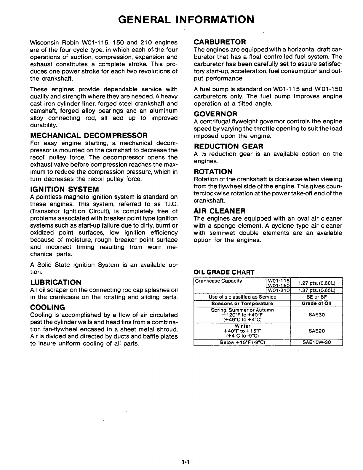
Figure
1-1.
Sectional Views
of
Engine Models
WO1-115
and
WO1-150
,-
1-2
VALVE
ROCKER
ARM
I
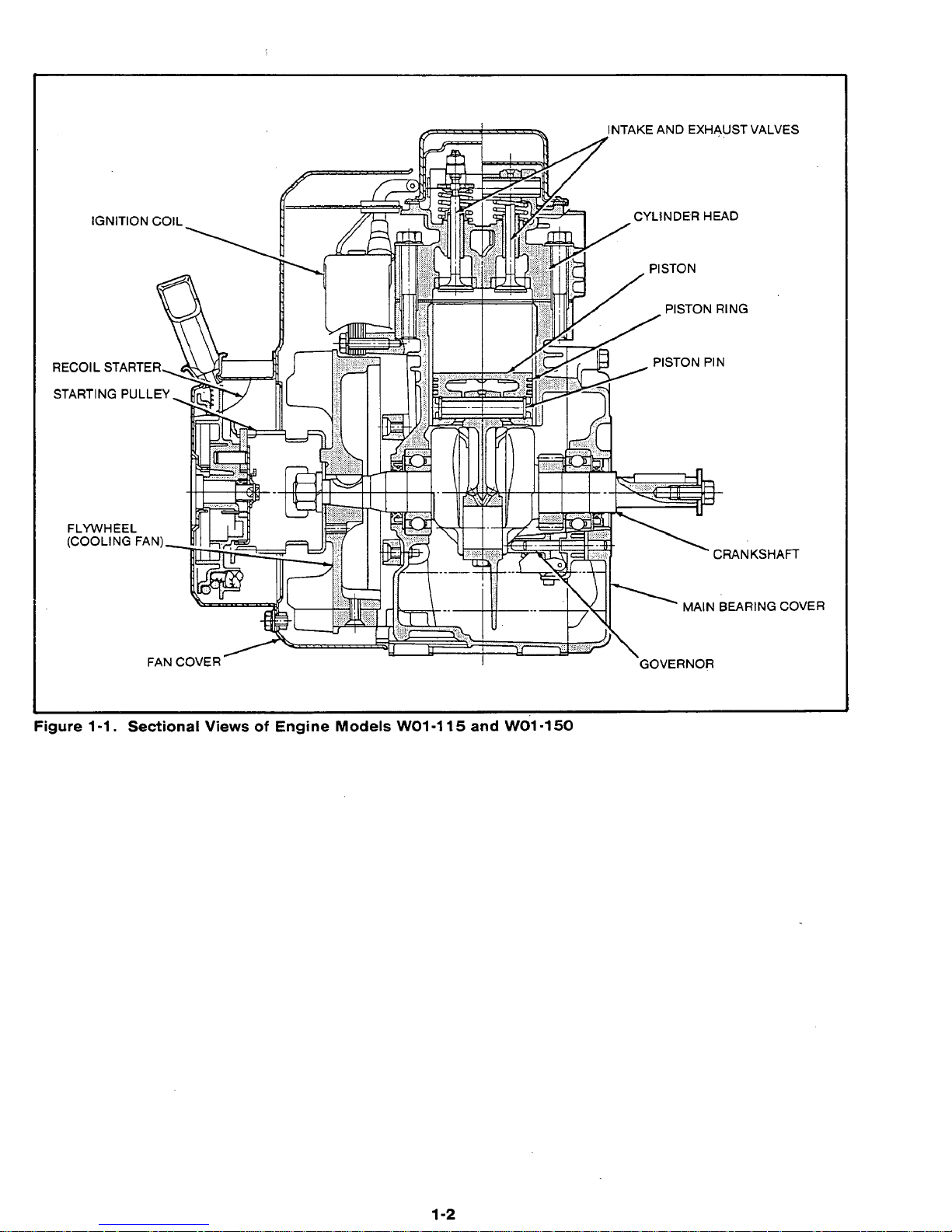
Figure 1-2. Sectional
View
of
Engine
Models
WO1-115 and WO1-150
1-3

Figure
1-3.
Sectional View
of
Engine Model
21
0
I
14
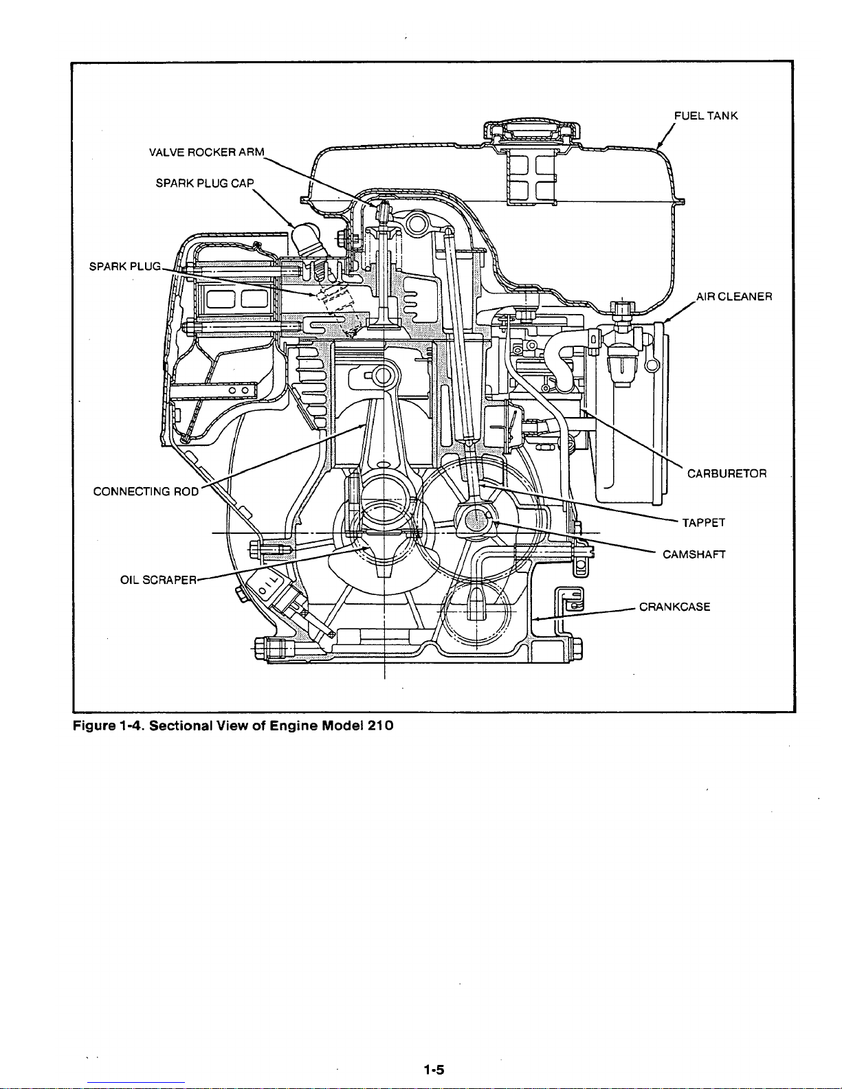
Figure
1-4.
Sectional
View
of
Engine Model
21
0
r
CAR3URETOR
1-5
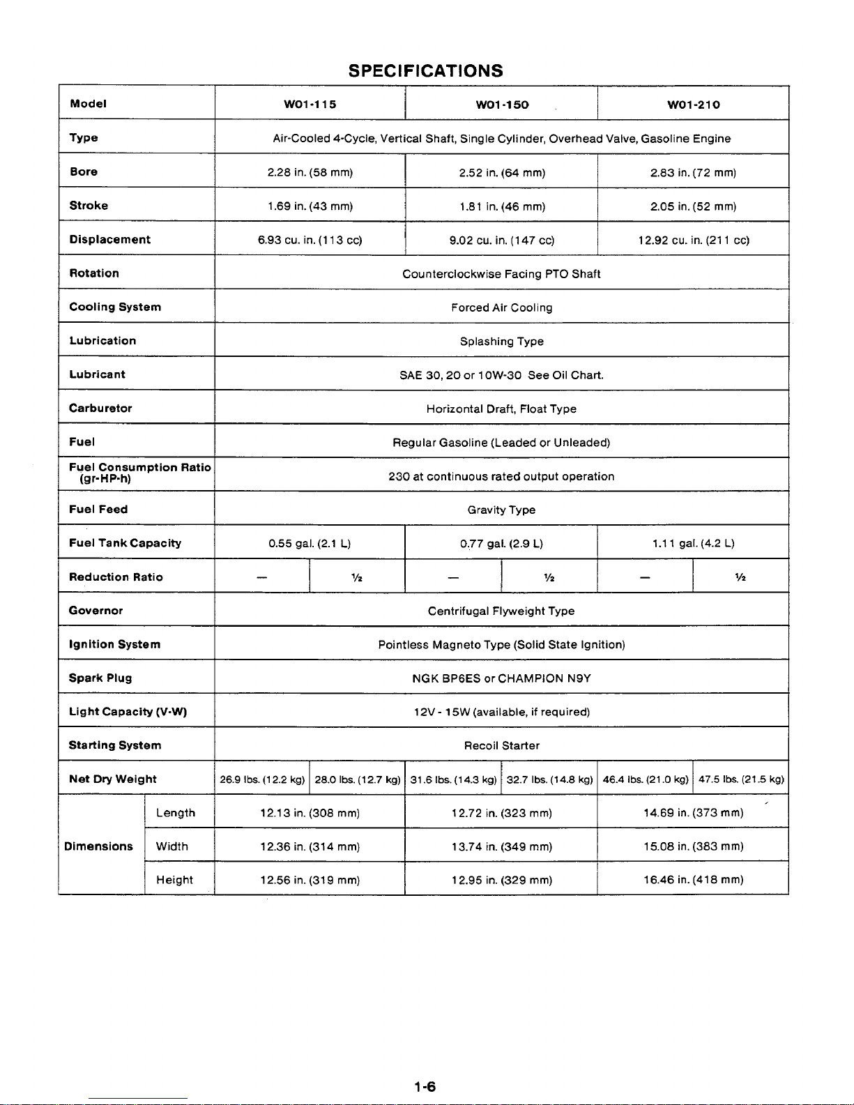
SPECIFICATIONS
Model
wo1-210 WO1-150
WO1-115
Type
2.28 in.
(58
rnm)
Bore
Air-Cooled 4-Cycle, Vertical Shaft, Single Cylinder, Overhead Valve, Gasoline Engine
2.05 in. (52
mm)
1.81 in. (46
mm)
1.69 in. (43
rnrn)
Stroke
2.83 in. (72
mrn)
2.52 in. (64
mrn)
Displacement
Forced
Air
Cooling
Cooling System
Counterclockwise Facing PTO Shaft
Rotation
12.92 cu. in. (21
1
cc) 9.02 cu. in. (1 47 cc)
6.93 cu. in. (1 13 cc)
Lubrication
SAE
30,20
or
1
OW-30
See Oil Chart.
Lubricant
Splashing Type
Carburetor
Regular Gasoline (Leaded or Unleaded)
Fuel
Horizontal Draft, Float Type
Fuel Consumption Ratio
(gr-HP-h)
230 at continuous rated output operation
Fuel Feed
Gravity Type
Fuel Tankcapacity
1.1
1 gal.
(4.2
L)
0..77 gal. (2.9
L)
0.55
gal. (2.1
L)
Reduction Ratio
'/2
-
'/2
-
'/2
-
Governor
Centrifugal Flyweight Type
Ignition System
NGK
BPGES
or
CHAMPION
N9Y
Spark Plug
Pointless Magneto Type (Solid State Ignition)
Light Capacity (V-W)
I
12V
-
15W (available,
if
required)
Starting System Recoil Starter
Net
Dry
Weight
47.5
Ibs.
(21.5 kg)
46.4 lbs(21.0 kg)
32.7 Ibs(l4.8 kg) 31.6 Ibs.(14.3
kg)
28.0 lbs.(12.7
kg)
26.9 Ibs(12.2 kg)
Starting System Recoil Starter
Net
Dry
Weight
47.5
Ibs.
(21.5 kg)
46.4 lbs(21.0 kg)
32.7 Ibs(l4.8 kg) 31.6 Ibs.(14.3
kg)
28.0 lbs.(12.7
kg)
26.9 Ibs(12.2 kg)
Length
15.08 in. (383
rnm)
13.74 in. (349 mm) 12.36 in. (31 4
mrn)
Width Dimensions
14.69 in. (373
rnm)
12.72
in.
(323
mm)
12.1 3 in. (308
rnrn)
Length
15.08 in. (383
rnm)
13.74 in. (349 mm) 12.36 in. (31 4
mrn)
Width Dimensions
14.69 in. (373
rnm)
12.72
in.
(323
mm)
12.1 3 in. (308
rnrn)
Height
16.46 in. (41
8
mm)
12.95 in. (329
rnrn)
12.56 in. (31
9
mm)
1
-6

MAINTENANCE AND STORAGE
ENGINE MAINTENANCE SCHEDULE
ACAUTION: Failure to follow this schedule will seriously damage the engine.
Daily
1
'
MAINTENANCE
Every
I
or 8 hrs.
I
20
hrs.
Add fuel
to
tank.
Check oil level. Add to
full mark.
Do
not overfill.
Clean air intake screen.
Clean cooling fins
if
needed.
0
Inspect unit for
loose hardware, lines,
or hoses.
Change crankcase oil.
Inspect cooling system.
Remove blower housing
and scrape between
fins, around cylinder
head and from housing.
0
a
I
Clean air cleaner.
I
I
Check and clean
Clean fuel filter and fuel
tank.
Clean contact and
breaker points.
Disassemble and clean
carburetor.
Remove carbon
from cylinder head.
Weekly
I
Monthly or I Semi-annual See Note
or
50
hrs.
100-200
hrs.
500-600
hrs. Below
*.
*
*
a
*
0
-*
I*
/.I
I*
1.
*Under severe environmental conditions these items may need to be maintained more frequently.
Cleaning
Air
Cleaner
Remove air cleaner cover. Remove element from base.
Wash element in detergent and hot water, then dry
thorou-ghly. Wipe all other components clean. Saturate
element with light oil. Squeeze firmly to evenly distribute oil and remove any excess.
Service daily
if
engine is operated in very dusty and dry
grass conditions.
A
clogged air cleaner will result in
high fuel consumption,
loss
of
power and excessive
carbon build-up in the combustion chamber.
ENGINE STORAGE
If not properly protected, temperature and humidity
changes can cause corrosion of piston rings, cylinder
walls and bearing surfaces in a stored engine. For maximum protection, prepare the engine for storage as
follows:
1.
Run the engine until it reaches operating temperature. Stop the engine and drain the oil from
crankcase while engine is still warm.
2-1
2.
Drain fuel lines, carburetor, fuel tank and fuel
pump
(if
equipped), to prevent lead and gum
sediment from. interfering with future operation.
Gasoline fumes from gradual evaporation are a
dangerous fire hazard.
3.
To
protect the internal components and keep
them from rusting and sticking, a half and half
mixture of kerosene and good engine oil (same
grade as used in the engine crankcase) should
be injected into the carburetor air intake.
Do
this
while the engine
is
warm and running at mod-
erate speed. Use enough of the mixture (about
l/4
pint)
so
that a heavy, bluish smoke appears at
the exhaust. This “fogging” operation will leave a
coating of oil on the parts, protecting them from
the atmosphere.
4.
Turn the starting pulley by hand and leave it
where the resistance is the heaviest.
5.
Tape
or
seal
off
air cleaner and exhaust
openings for the duration
of
the storage
period.
6.
Remove all dirt and chaff from the cooling
fins.
7.
Clean the engine outside with an oiled cloth.
8.
It
is highly recommended that machines be
stored inside a building through the winter.
If
this
is not possible, the engine should be protected
from snow and ice by a suitable covering.
NOTE: Before adding new crankcase oil the next
season, drain engine
of
condensation which
may have accumulated in the crankcase during the storage period. Fill crankcase with
good quality oil before starting engine
(see ‘SPECIFICATIONS).
2-2
The three prime requirements necessary for starting and maintaining satisfactory operation
of
gasoline engines
are:
1.
A
proper fuel mixture in the cylinder
2.
Good compression in the cylinder.
3.
Good spark at the correct time, to ignite the mixture.
There are other factors which contribute to hard starting; such as too heavy a load for the engine to turn over at
low starting speed, long exhaust pipe with high back pressure, etc. These conditions may affect starting, but do
not necessarily mean the engine is improperly adjusted.
The most common symptoms of engine problems are given here, followed by the probable causes.
ENGINE
WILL
NOT
START, OR HARD
TO
START
Electrical System Problems Caused By:
Weak or dead battery.
Poor ground connection.
Defective starter.
Fuel System Problems Caused By:
Fuel tank empty. Improper or contaminated
fuel.
Carburetor not choked enough (cold engine).
Low
cranking
speed.
Restricted cooling air circulation.
Loose fittings or defective fuel lines.
Carburetor needle valve held open by dirt or
gum.
Defective speed control or governor.
Fuel or oil leaks.
Ignition System Problems Caused By:
Loose
or
corroded electrical connections.
Ignition wires disconnected or broken.
Damaged or loose ignition module.
Faulty ignition coil.
Spark plug cable wet or broken.
Spark plug wet or dirty.
Spark ptug point gap incorrect.
Compression System Problems Caused By:
Lack of lubrication on moving parts due to
long storage.
Incorrect oil grade or
low
oil
level.
Loose or broken spark plug.
Damaged head gasket or loose cylinder
head.
Incorrect tappet clearance.
Valve stuck open due to carbon or gum on
valve stem.
Defective or incorrectly adjusted valve com-
ponents.
Worn valve guides, piston or rings.
Scored or worn cylinder walls.
3-1
ENGINE
MISFIRES
Incorrect spark plug gap.
Ignition cable leaking.
Weak spark
Ignition wires loose.
Water or dirt in gasoline.
Insufficient compression.
ENGINE
STOPS
Fuel tank empty.
Water, dirt, gum, etc. in gasoline.
Vapor lock (gasoline evaporating in fuel lines
due to excessive heat around engine).
Vapor lock in fuel lines or carburetor
due to incorrect fuel.
Engine scored
or
stuck due to lack of oil.
Air vent hole in the fuel tank cap plugged.
Magneto or ignition coil faulty.
ENGINE OVERHEATS
Crankcase oil level
low.
Spark timing incorrect.
Low
grade gasoline used.
Engine overloaded.
Cooling air restricted from dirt
or
debris.
Engine operated in confined space where cooling air is continually recirculated.
Restricted exhaust.
Heavy load
at
low engine speed.
0
ENGINE KNOCKS
Low quality gasoline.
Engine operating under heavy load at
low
speed.
Carbon or lead deposits in cylinder head
or
on piston.
Spark timing incorrect.
Worn
or
damaged connecting rod bearing.
Worn or damaged piston pin.
ENGINE BACKFIRES THROUGH
CARBURETOR
Water or dirt in gasoline, or poor grade
gasoline.
Intake valve stuck
Valves overheated,
or
particles in combustion
chamber.
Engine cold.
ENGINE SURGES
OR
GALLOPS
Carburetor flooded.
Governor rod installed wrong, or governor out
of adjustment.
High speed jet
in
carburetor partially
restricted.
/?
3-2
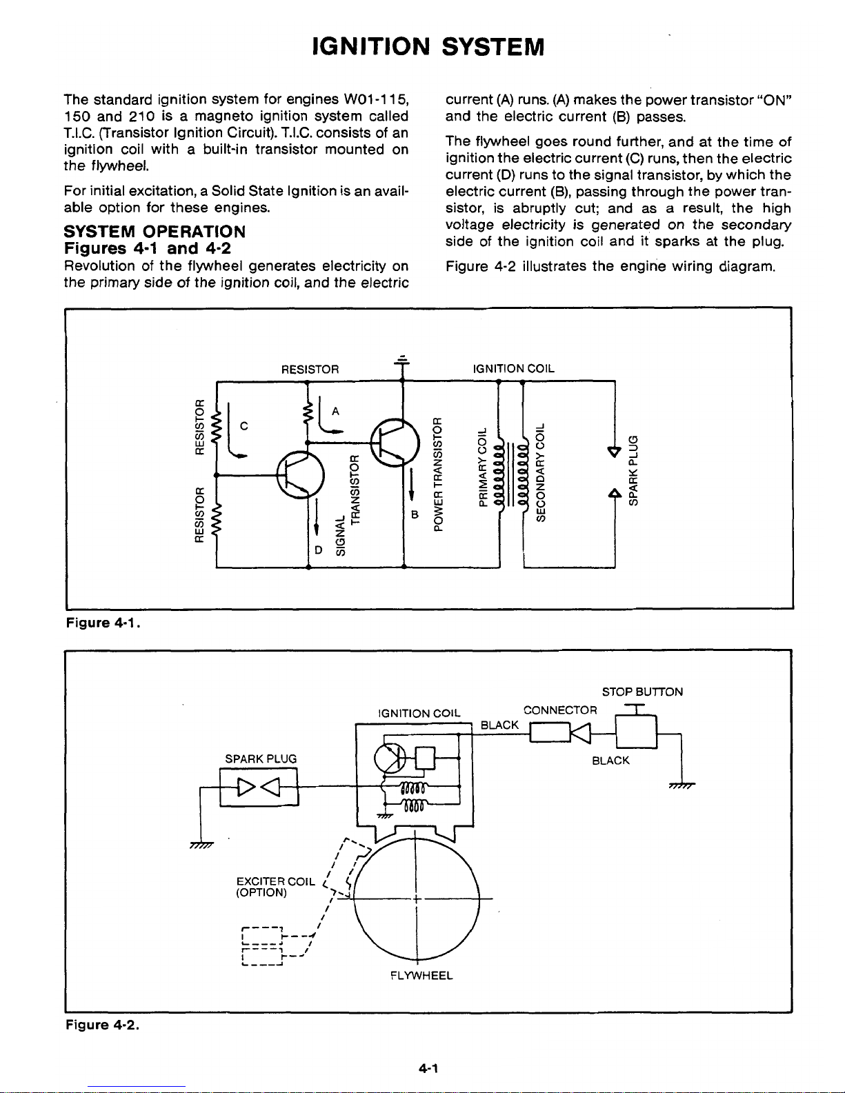
IGNITION
The standard ignition system for engines
WO1-115,
150
and
210
is a magneto ignition system called
T.I.C. (Transistor Ignition Circuit). T.I.C. consists
of
an
ignition coil with a built-in transistor mounted on
the flywheel.
For initial excitation, a Solid State Ignition is an available option for these engines.
SYSTEM
OPERATION
Figures
4-1
and
4-2
Revolution
of
the flywheel generates electricity on
the primary side
of
the ignition coil, and the electric
SYSTEM
current
(A)
runs.
(A)
makes the power transistor
"ON"
and the electric current
(B)
passes.
The flywheel goes round further, and at the time
of
ignition the electric current (C) runs, then the electric
current
(D)
runs
to
the signal transistor, by which the
electric current
(B),
passing through the power transistor, is abruptly cut; and as a result, the high
voltage electricity
is
generated on the secondary
side
of
the ignition coil and it sparks at the plug.
Figure
4-2
illustrates the engine wiring diagram.
-
RESISTOR
f
IGNITION
COIL
Figure
4-1.
STOP
BUlTON
IGNITION COIL CONNECTOR
-r
SPARK
PLUG BLACK
mrr
(OPTION)
EXCITER
COIL
(
I
I
l""1
I
i
FLYWHEEL
Figure
4-2.
4-
1
 Loading...