

Page 1
SERVICE
MANUAL
IVIodel
EH18V OHV
396S322
Page 2
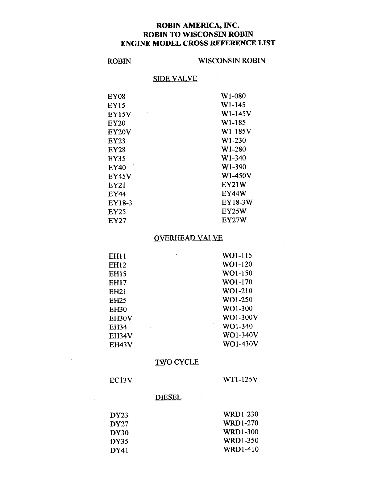
ROBIN
AMERICA, INC.
ROBIN
TO
WISCONSIN
ROBIN
ENGINE
MODEL
CROSS REFERENCE
LIST
ROBIN
EY08
EY15
EY 15V
EY20
EY2OV
EY23
EY28
EY3
5
EY40
-
EY45V
EY2
1
EY44
EY 18-3
EY25
EY27
EH11
EH12
EH15
EH17
EH21
EH25
EH30
EH30V
EH34
EH34V
EH43V
EC13V
DY23
DY27
DY30
DY3
5
DY4 1
WISCONSIN
ROBIN
SIDE
VALVE
W
1-080
W1-145
W1-145V
W1-185
W1-185V
W1-230
W 1-280
W
1-340
W 1-390
Wl-45OV
EY21W
EY44W
EY18-3W
EY25W
EY27W
OVERHEAD
VALVE
WO1-115
wo1-120
WO1-150
WO1-170
wo1-210
WOl-250
WO 1-300
WO1-300V
WO1-340
WO
1
-340V
WO 1-43 OV
TWO CYCLE
WT1-125V
DIESEL
WRD
1-230
WRD
1-270
-1-300
WRD1-350
WRD1-410
0
0
0
Page 3
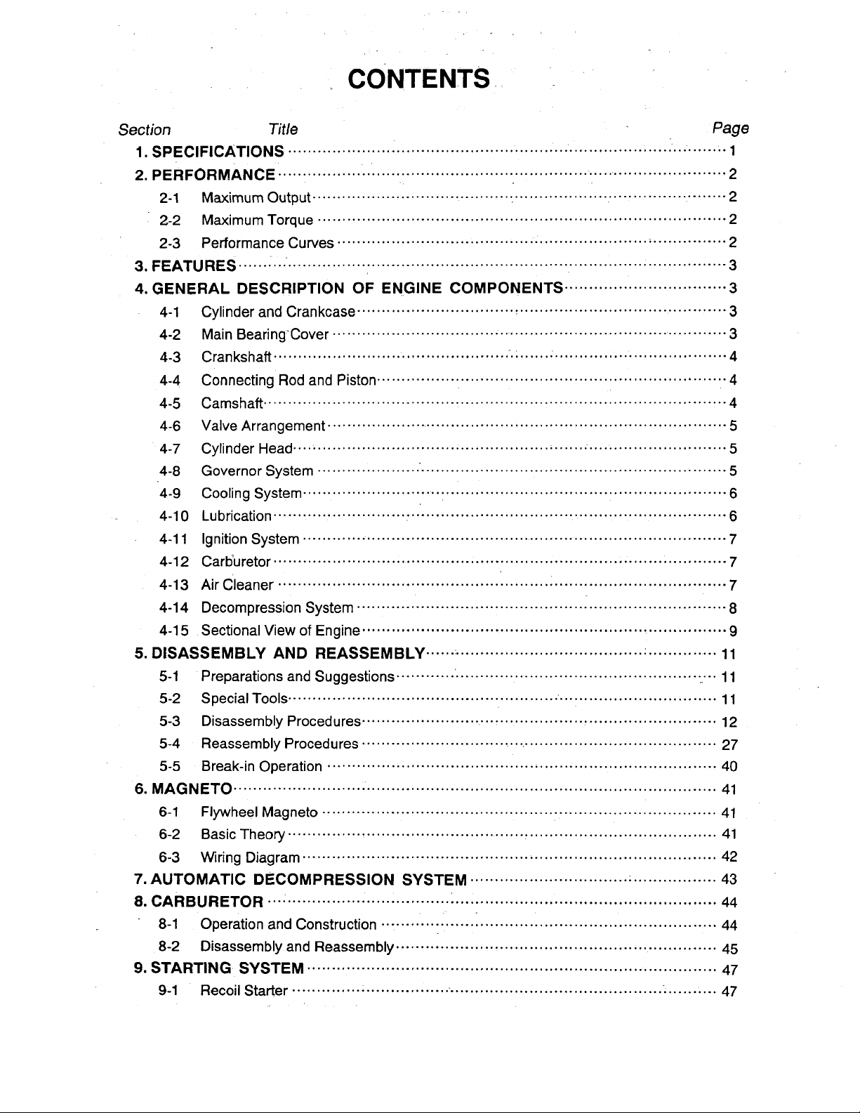
CONTENTS
.
Section
Title
Page
1
. SpEClF[CATlONS
.........................................................................................
1
2.
PERFORMANCE ............................................................................................
2
2-1 Maximum Output
....................................................................................
2-2
Maximum Torque
...................................................................................
2
2
2-3 Performance Curves
...............................................................................
2
3
4.GENERAL DESCRIPTION OF ENGINE COMPONENTS .................................
3
3
. FEATURES
...................................................................................................
4-1
4-2
4-3
4-4
4-5
4-6
4-7
4-8
4-9
4-1
0
4-1 1
4-1 2
4-1 3
4-1
4
4-1
5
5
. DISASSEMBLY AND REASSEMBLY
............................................................
11
.
11
11
12
27
5-5
Break-in Operation
...............................................................................
40
41
6-1 Flywheel Magneto
................................................................................
41
41
5-1 Preparations and Suggestions
..................................................................
5-2 Special
Tools
.......................................................................................
5-3
Disassembly Procedures
........................................................................
5-4 Reassembly Procedures
.........................................................................
6 . MAGNETO
..................................................................................................
6-2 Basic The0
ry
.......................................................................................
6-3
Wiring Diagram
....................................................................................
42
7.AUTOMATlC DECOMPRESSlON SYSTEM
..................................................
43
8.CARBURETOR
...........................................................................................
44
.
8-1 Operation and Construction
....................................................................
44
45
47
47
8-2
Disassembly and Reassembly
.................................................................
9 . STARTING SYSTEM
...................................................................................
9-1 Recoil Starter
........................................................................................
Page 4
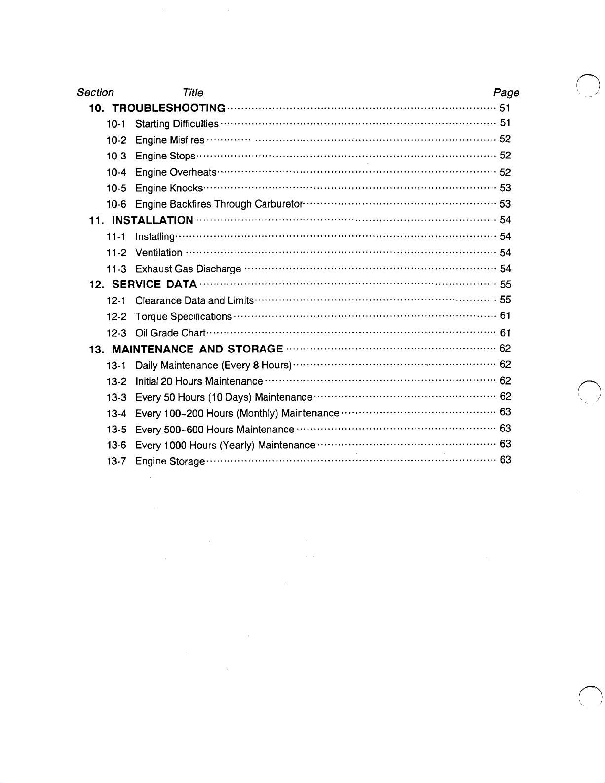
Section
10.
TROUBLESHOOTlNG
10-1 Starting Difficulties
10-2 Engine Misfires
10-3 Engine Stops
10-4 Engine Overheats
10-5 Engine Knocks
10-6
Engine BacMires Through Carburetor
11
.
lNSTALMTlON
11-1 Installing
11-2 Ventilation
11-3 Exhaust Gas Discharge
12
. SERVICE DATA
12-1 Clearance Data and Limits
12-2 Torque Specifications
12-3 Oil Grade Chart
13.
MAINTENANCE AND
13-1 Daily Maintenance (Every
13-2 Initial
13-3
Every
13-4 Every 100-200 Hours (Monthly) Maintenance
13-5 Every
13-6 Every
13-7 Engine Storage
Title
..............................................................................
................................................................................
....................................................................................
.......................................................................................
.................................................................................
.....................................................................................
.......................................................................................
.............................................................................................
..........................................................................................
.........................................................................
......................................................................................
......................................................................
............................................................................
....................................................................................
STORAGE
8
Hours)
20
Hours Maintenance
50
Hours (10 Days) Maintenance
500-600
1
000
Hours Maintenance
Hours (Yearly) Maintenance
....................................................................................
...................................................................
Page
51
51
52
52
52
53
........................................................
.............................................................
............................................................
53
54
54
54
54
55
55
61
61
62
62
62
.....................................................
.............................................
..........................................................
....................................................
62
63
63
63
63
..
Page 5
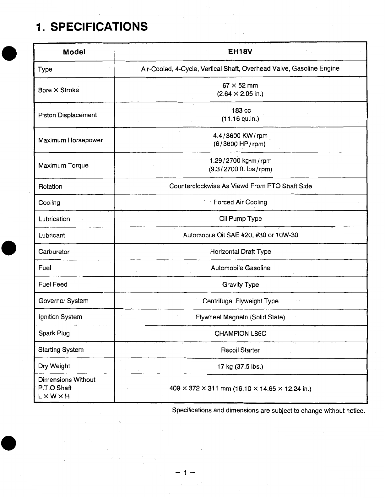
1.
SPECIFICATIONS
Model
TY
Pe
Bore
X
Stroke
Piston Displacement
Maximum Horsepower
Maximum Torque
~ ~ ~~~~
Rotation
Cooling
~
Lubrication
EH18V
Air-Cooled, 4-Cycle, Vertical Shaft, Overhead Valve, Gasoline Engine
(2.64
4.4 /3600
(6/3600
1.29 / 2700
(9.3/2700
Counterclockwise
'
'
Forced Air Cooling
67 X 52
(1 1.1 6
As
Oil Pump Type
mm
X
2.05
in.)
183
cc
c,u.in.)
KW/
rpm
HP/rpm)
kg-m / rpm
ft. Ibs/rpm)
Viewd From PTO Shaft Side
Lubricant
Carburetor
Fuel
Fuel Feed
~ ~~ ~ ~~
Governor System
Ignition System
Spark Plug
Starting System
Dry Weight
Dimensions Without
P.T.0
Shaft
LXWXH
I
Oil
SAE
Automobile
Horizontal Draft Type
Automobile Gasoline
Gravity Type
Centrifugal Flyweight Type
Flywheel Magneto (Solid State)
CHAMPION
Recoil
17
409 X 372
Specifications and dimensions are subject to change without notice.
x
31 1 mm
#20, #30 or 1OW-30
L86C
Starter
kg
(37.5
Ibs.)
(16.10 X 14.65 x 12.24
in.)
-1-
Page 6
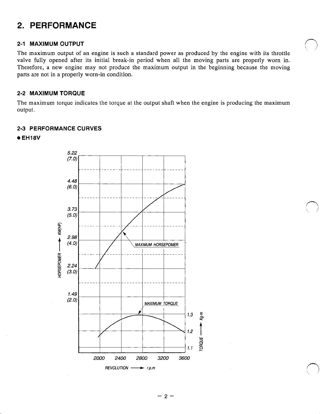
2.
PERFORMANCE
2-1
MAXIMUM OUTPUT
The maximum output
valve fully opened after its initial break-in period when all the moving parts are properly worn in.
Therefore, a new engine may not produce the maximum output in the beginning because the moving
parts are not in a properly worn-in condition.
2-2
MAXIMUM TORQUE
The maximum torque indicates the torque at the output shaft when the engine is producing the maximum
output.
2-3
PERFORMANCE CURVES
EH18V
of
an engine
5.2;
(7.
0
Tn"--r
4.41
(6.0
is
such a standard power
""_~_
as
produced by the engine with
"""
"""_
"""
its
throttle
7.4!
(2.
0
2000 2400 2800 3200
REVOLUTlON
-
3600
r.p.m
"i
-2-
Page 7
3.
FEATURES
1.
The overhead valve design offers compactness, light weight and ideal combustion characteristics
resulting in more power
2.
The parts
3.
The automatic decompression system offers easy and sure starting.
4.
The muffler and carburetor are located
flow
5.
The oil pump and oil filter provide excellent lubrication regardless of engine posture during
operation.
6.
This engine
7.
The Pro-Poly version engine is covered with a stylishly designed
fuel tank incoroprated into it.
'8.
The Classic Steel version does not have the shroud or combined fuel tank.
4.
GENERAL DESCRIPTION
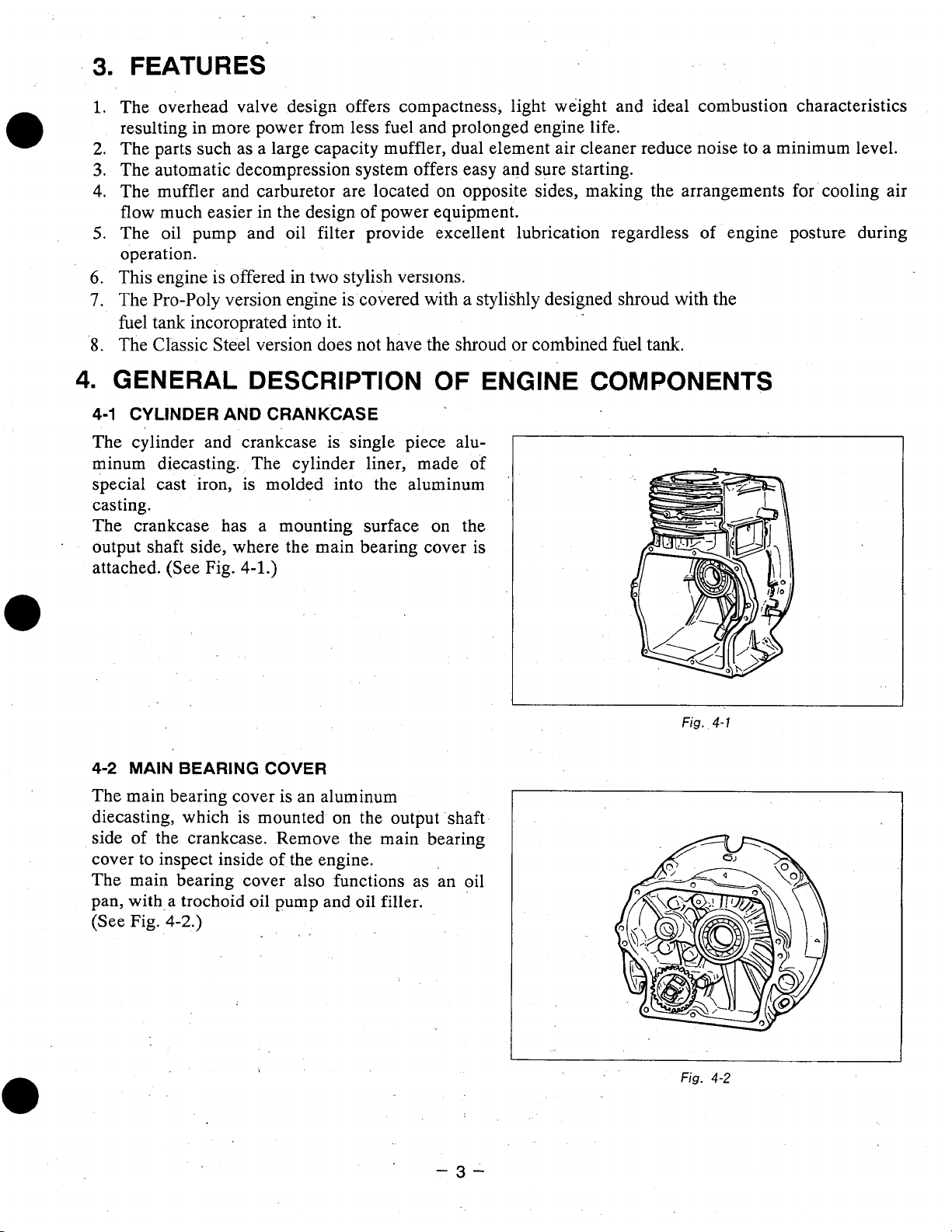
4-1
CYLINDER AND CRANKCASE
The cylinder and crankcase is single piece aluminum diecasting. The cylinder liner, made of
special cast iron, is molded into the aluminum
casting.
The crankcase has a mounting surface
output shaft side, where the main bearing cover is
attached. (See Fig.
such
as a large capacity muffler, dual element air cleaner reduce noise
much easier in the design of power equipment.
is
offered in two stylish versions.
4-1.)
from
less fuel and prolonged engine life.
on
opposite sides, making the arrangements
OF
on
ENGINE COMPONENTS
the
shroud
with the
to
a minimum level.
for
cooling air
4-2
MAIN BEARING
The main bearing cover is an aluminum
diecasting, which is mounted
side of the crankcase. Remove the main bearing
cover
to
inspect inside
The main bearing cover also functions as an oil
pan, with,a trochoid
(See Fig.
4-2.)
COVER
of
the engine.
oil
pump and
..
on
the output shaft
oil
filler.
-3-
Fig.
Fig.
4-1
4-2
Page 8
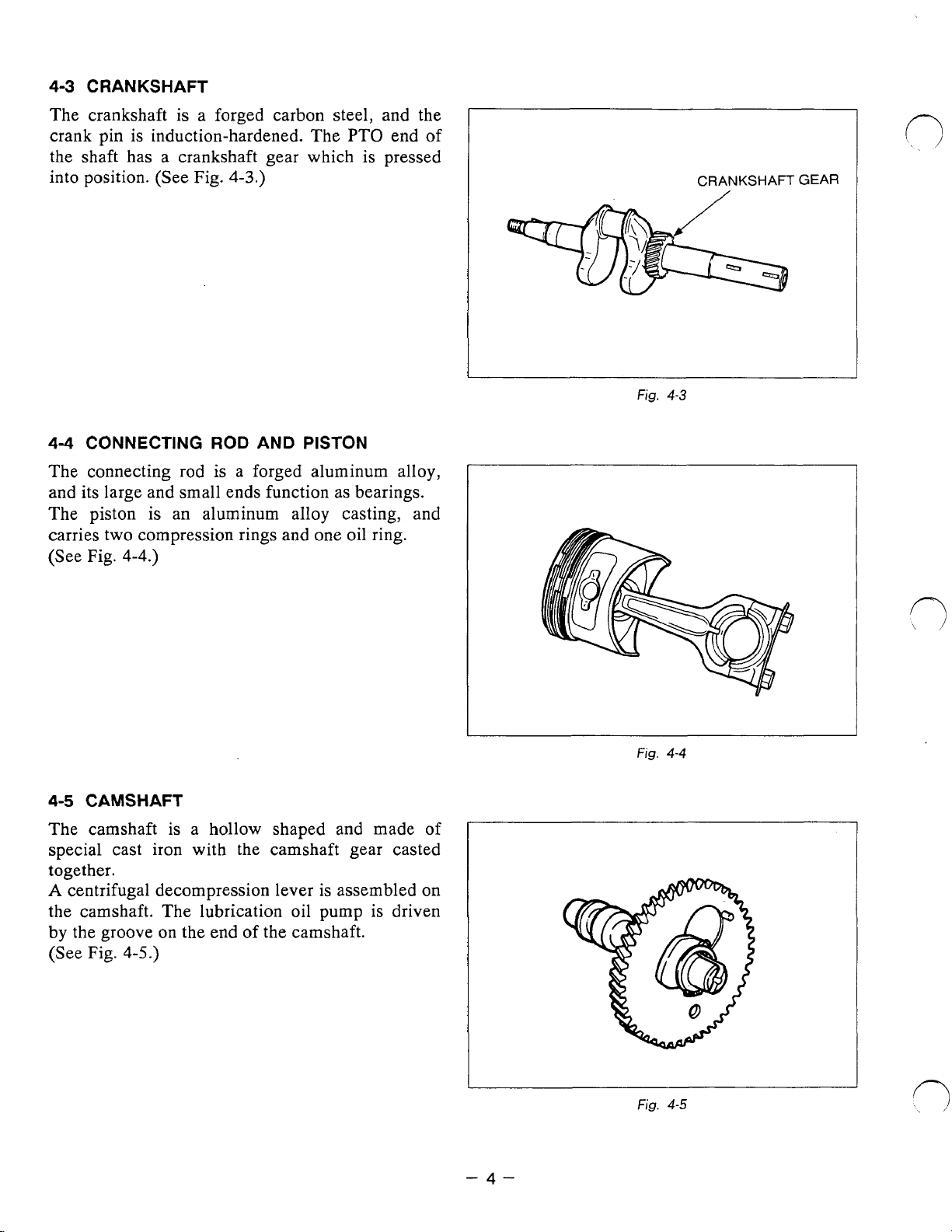
4-3
CRANKSHAFT
The crankshaft is a forged carbon steel, and the
crank pin
is
induction-hardened. The PTO end
the shaft has a crankshaft gear which is pressed
into position. (See
44
CONNECTING
Fig.
ROD
4-3.)
AND PISTON
of
Fig.
CRANKSHAFT
4-3
r,
GEAR
The connecting rod
is
a forged aluminum alloy,
and its large and small ends function as bearings.
The piston
4-5
CAMSHAFT
The camshaft is a hollow shaped
is
an aluminum alloy casting, and
and
made of
special cast iron with the camshaft gear casted
together.
A
centrifugal decompression lever is assembled
the camshaft. The lubrication oil
by the groove
(See Fig.
4-5.)
on
the end of the camshaft.
pump
is driven
on
Fig.
4-4
-4-
Fig.
4-5
Page 9
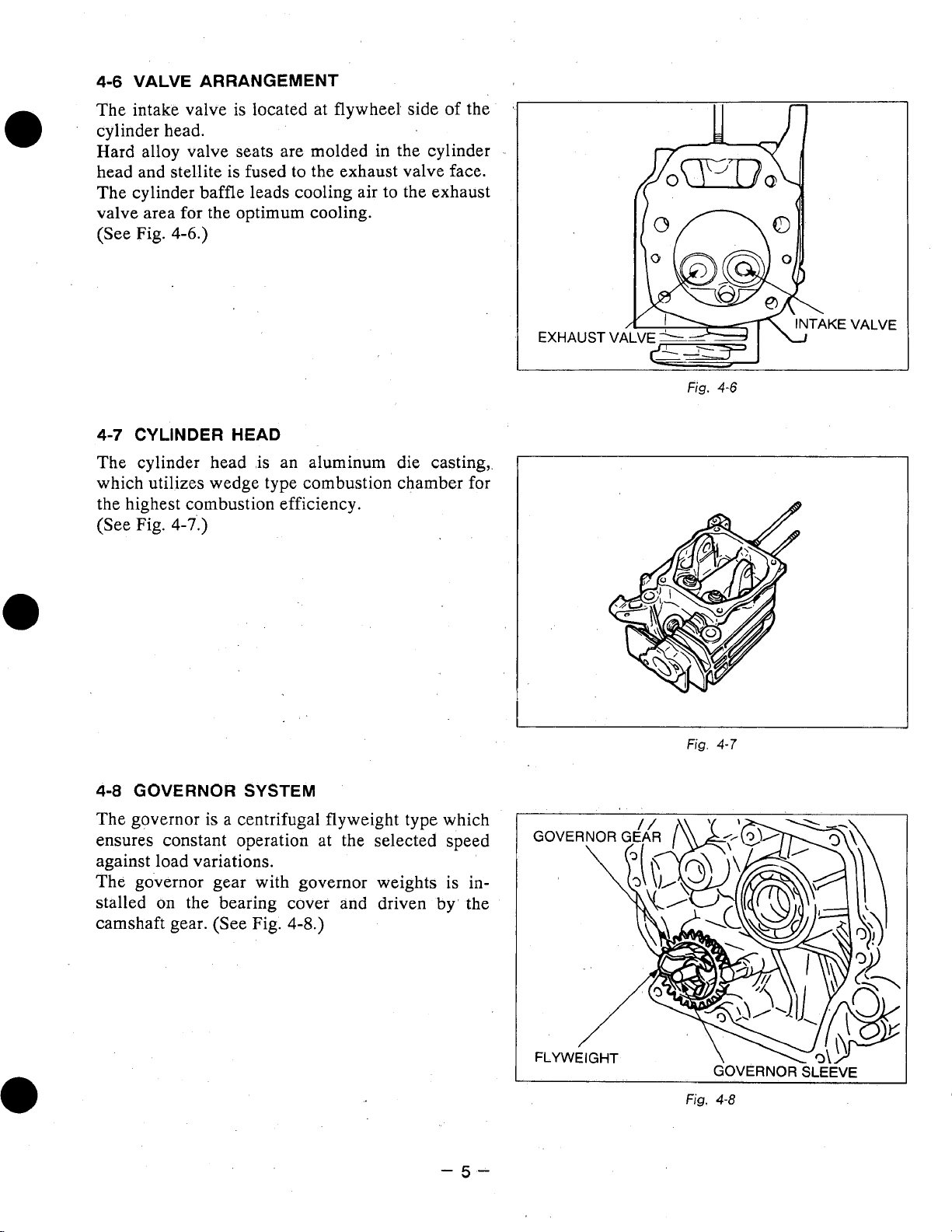
4-6
VALVE ARRANGEMENT
The intake valve is located at flywheel side
'
cylinder head.
of
the
Hard alloy valve seats are molded in the cylinder
head and stellite is fused to the exhaust valve face.
The cylinder baffle leads cooling air to the exhaust
valve area for the optimum cooling.
(See
Fig.
4-6.)
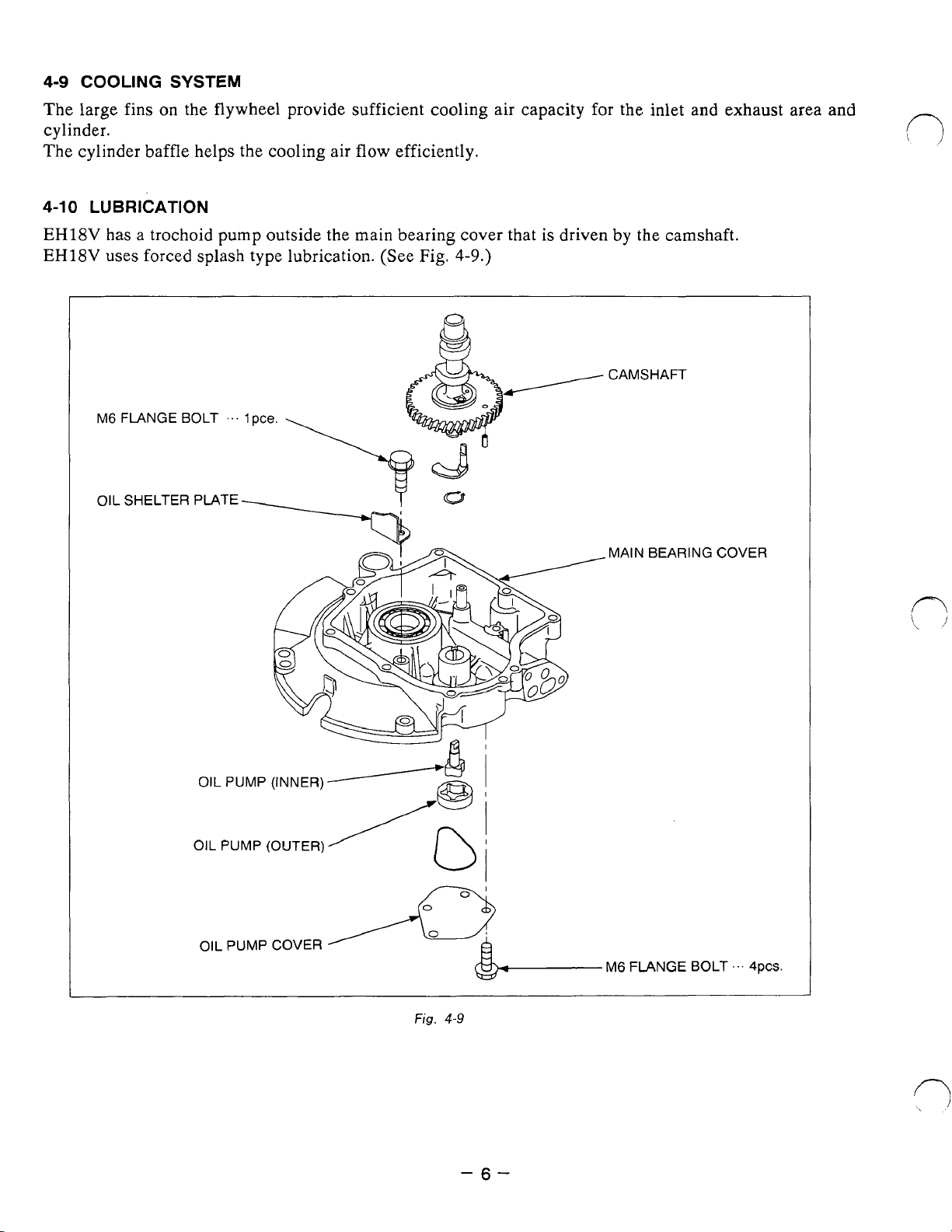
4-7
CYLINDER HEAD
The cylinder head ,is an aluminum die casting,.
which utilizes wedge type combustion chamber for
the highest combustion efficiency.
(See Fig.
4-7.)
EXHAUST
Vi
Fig.
II
4-6
n
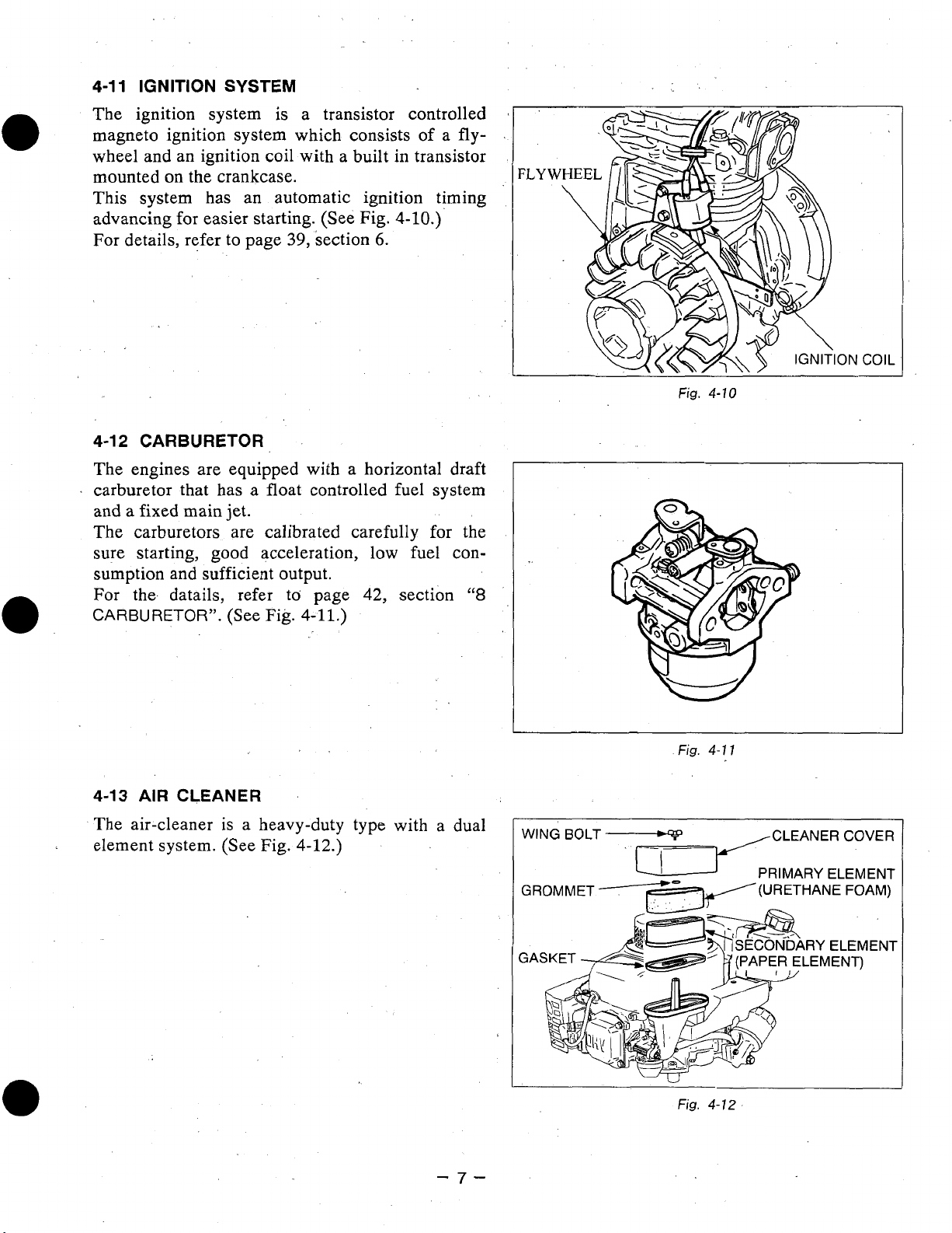
4-8
GOVERNOR SYSTEM
The governor is a centrifugal flyweight type which
ensures constant operation at the selected speed
against load variations.
The governor gear with governor weights is installed on the bearing cover and driven
camshaft gear. (See Fig.
4-8.)
by'
the
-5-
Fig.
Fig.
4-7
4-8
Page 10
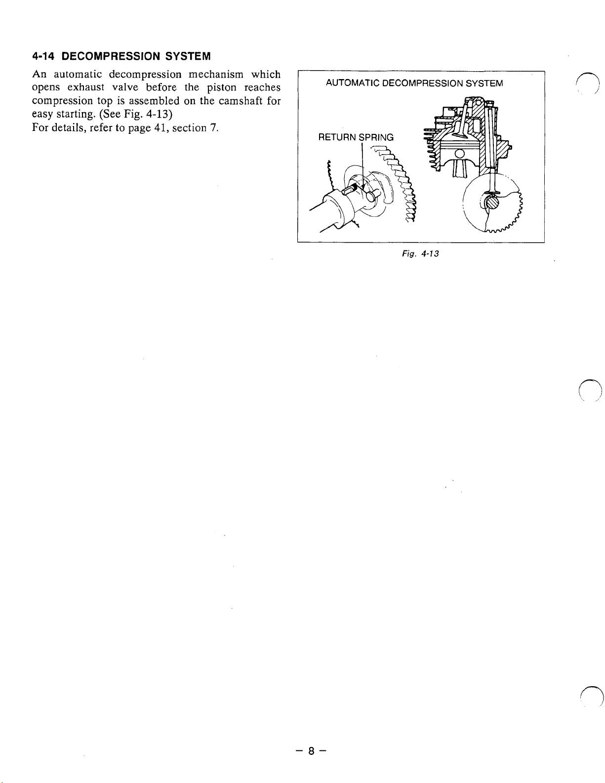
4-9
COOLING SYSTEM
The large fins
on
the flywheel provide sufficient cooling air capacity for the inlet and exhaust area and
cylinder.
The cylinder baffle helps the cooling air flow efficiently.
4-1
0
LUBRICATION
EH18V
EH18V
has a trochoid pump outside the main bearing cover that is driven by the camshaft.
uses
forced
splash
type lubrication.
(See
Fig.
4-9.)
/
M6
FLANGE BOLT
OIL
SHELTER
...
PLATE
1
pce.
CAMSHAFT
M,
AIN BEARING
COVER
OIL PUMP
COVER
Fig.
4-9
-6-
&-
M6
FLANGE
BOLT
...
4pcs.
Page 11
4-1
1
IGNITION
The
ignition system
magneto ignition system which consists of a
SYSTEM
is
a transistor controlled
fly-
wheel and an ignition coil with a built in transistor
mounted on the crankcase.
This system has an automatic ignition timing
advancing for easier starting. (See Fig.
For details, refer to page
39,
section
4-10.)
6.
4-12
CARBURETOR
The engines are equipped with a horizontal draft
carburetor
that
has a float controlled
and a fixed main jet.
The carburetors are calibrated carefully for the
sure starting,
good
acceleration, low fuel consumption and sufficient output.
For the- datails, refer
CARBURETOR”.
4-13
AIR
The air-cleaner
.
element system. (See
(See
CLEANER
is
to
page 42, section
Fig.
4-11.)
a heavy-duty type with a dual
Fig.
4-12.)
fuel
system
“8
WING
BOLT
GROMMET
I;’
eo
.
Fig.
4-1
1
<
#(URETHANE FOAM)
:’
.
.’
J
CLEANER COVER
PRIMARY ELEMENT
-7-
Fig.
SECONDARY ELEMENT
SECONDARY ELEMENT
PAPER ELEMENT)
(PAPER ELEMENT)
4-12
Page 12
4-14
DECOMPRESSION
An
automatic decompression mechanism which
opens exhaust valve
compression top is assembled
easy starting. (See
For details, refer
to
Fig.
page
SYSTEM
before
4-13)
41,
the piston reaches
on
section
the camshaft for
7.
[
AUTOMATIC DECOMPRESSION
RETURN SPRING
&$
SYSTEM
n
-a-
Page 13
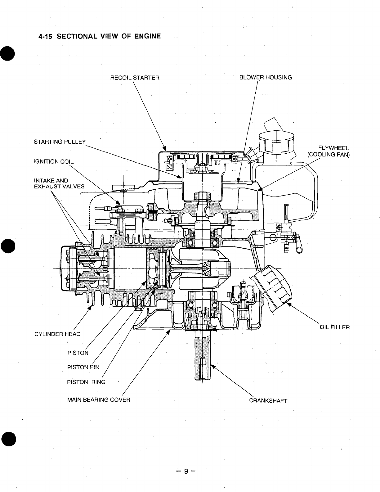
4-15
SECTIONAL
VIEW
OF
ENGINE
RECOIL
STARTER
\
BLOWER
I
HOUSING
MAIN
BEARING COVER
-9-
CRANKSHAFT
Page 14
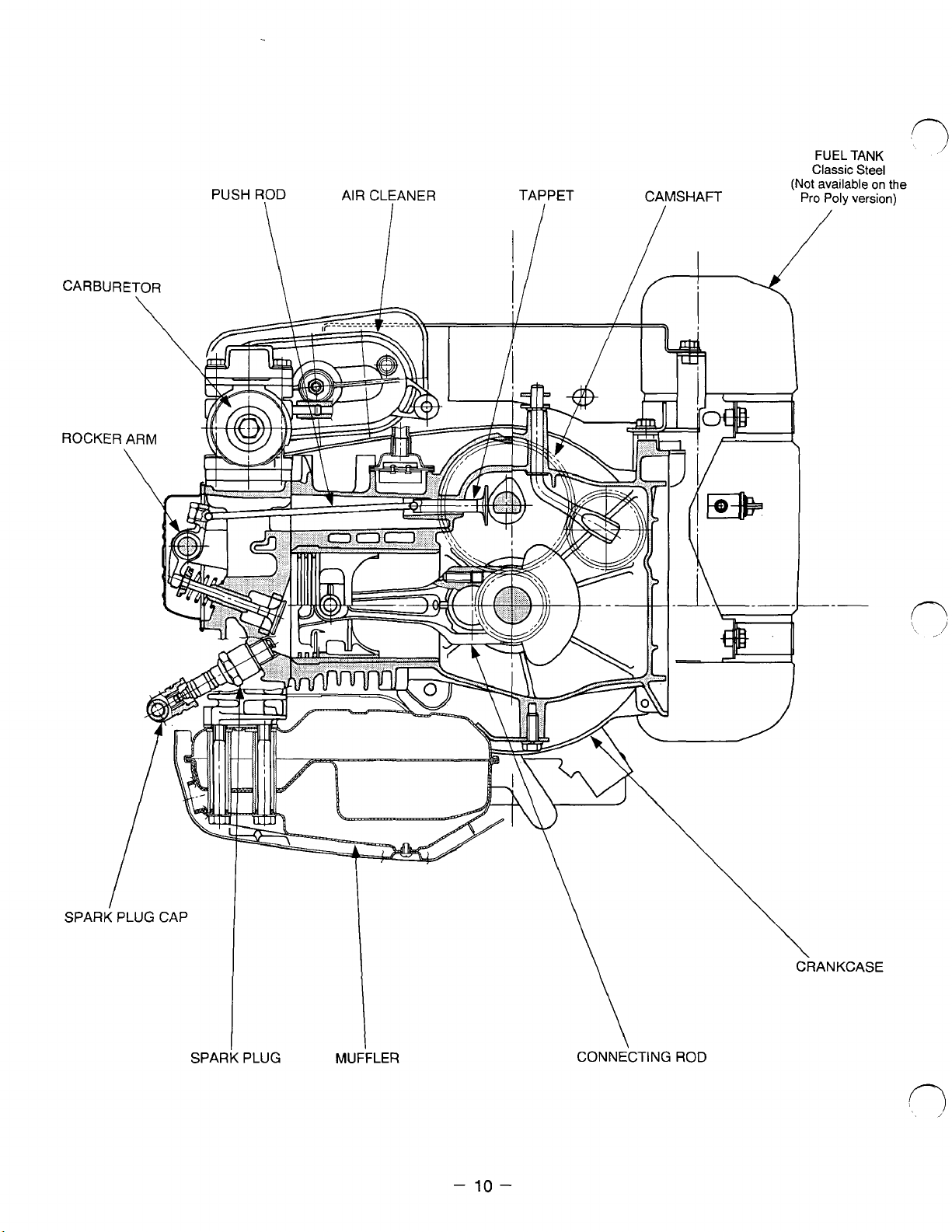
SPARK
PLUG
MUFFLER
CONNECTING
-
10
-
ROD
Page 15
5.
DISASSEMBLY
5-1
PREPARATIONS AND SUGGESTIONS
AND
REASSEMBLY
When disassembling the engine, remember the locations
1)
reassembled correctly. If you are uncertain of identifying some parts,
attached to them.
Have boxes ready to keep disassembled parts
To
prevent missing and misplacing, temporarily assemble each group
Carefully handle disassembled parts, and clean them with
in
Use the correct tools
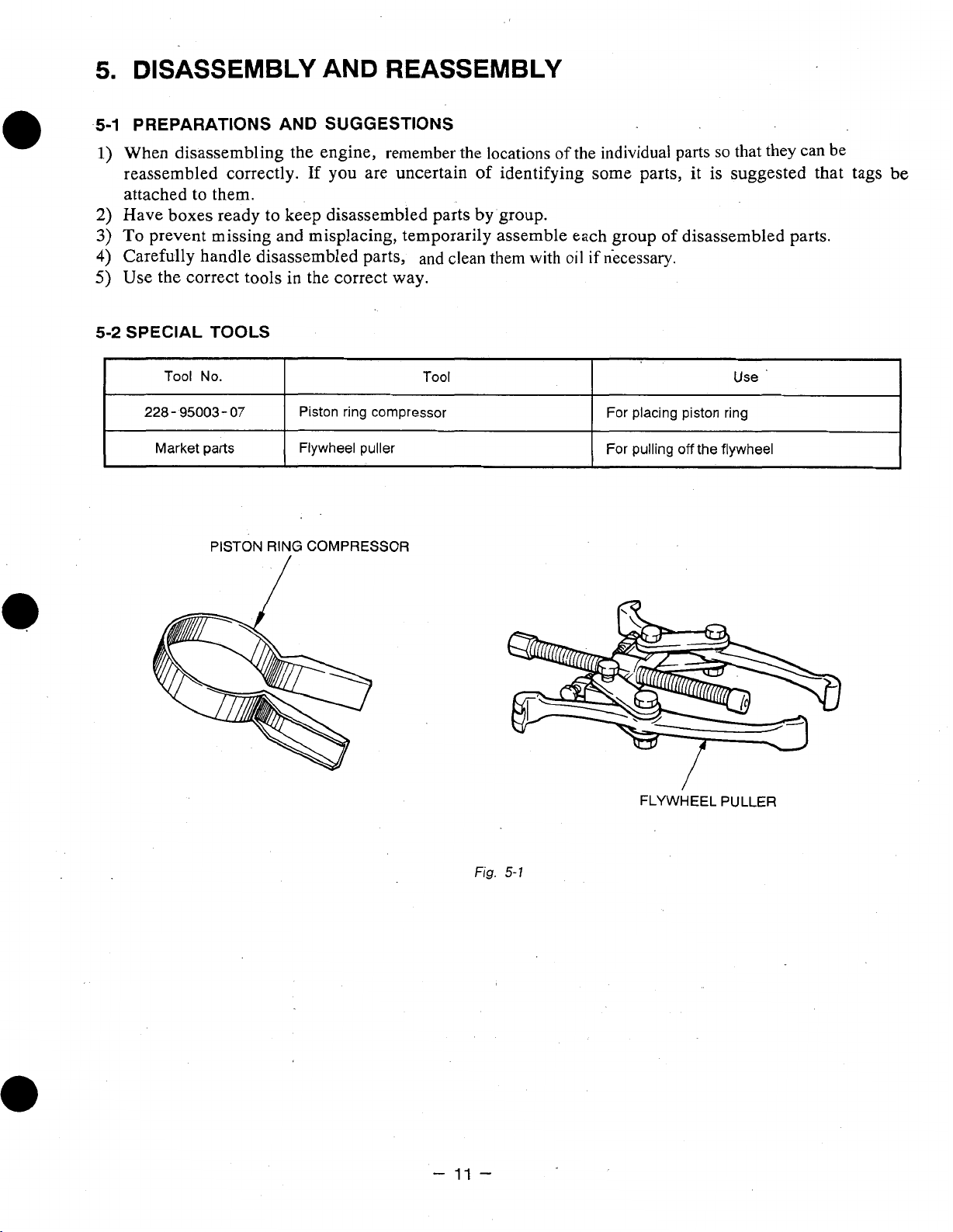
5-2
SPECIAL
I
I
228-
I
Market
TOOLS
Tool No.
95003-07
parts
PISTON
the correct way.
I
I
Piston ring compressor
I
Flywheel puller
RING
COMPRESSOR
Tool
by
group.
of
the individual parts
oil
if
necessary.
I
I
For placing piston ring
1
For
/
/
of
pulling
so
that they can be
it
is suggested that tags
disassembled parts.
Use
off
the flywheel
be
I
I
I
-
11
Fig.
-
FLYWHEEL PULLER
5-1
Page 16
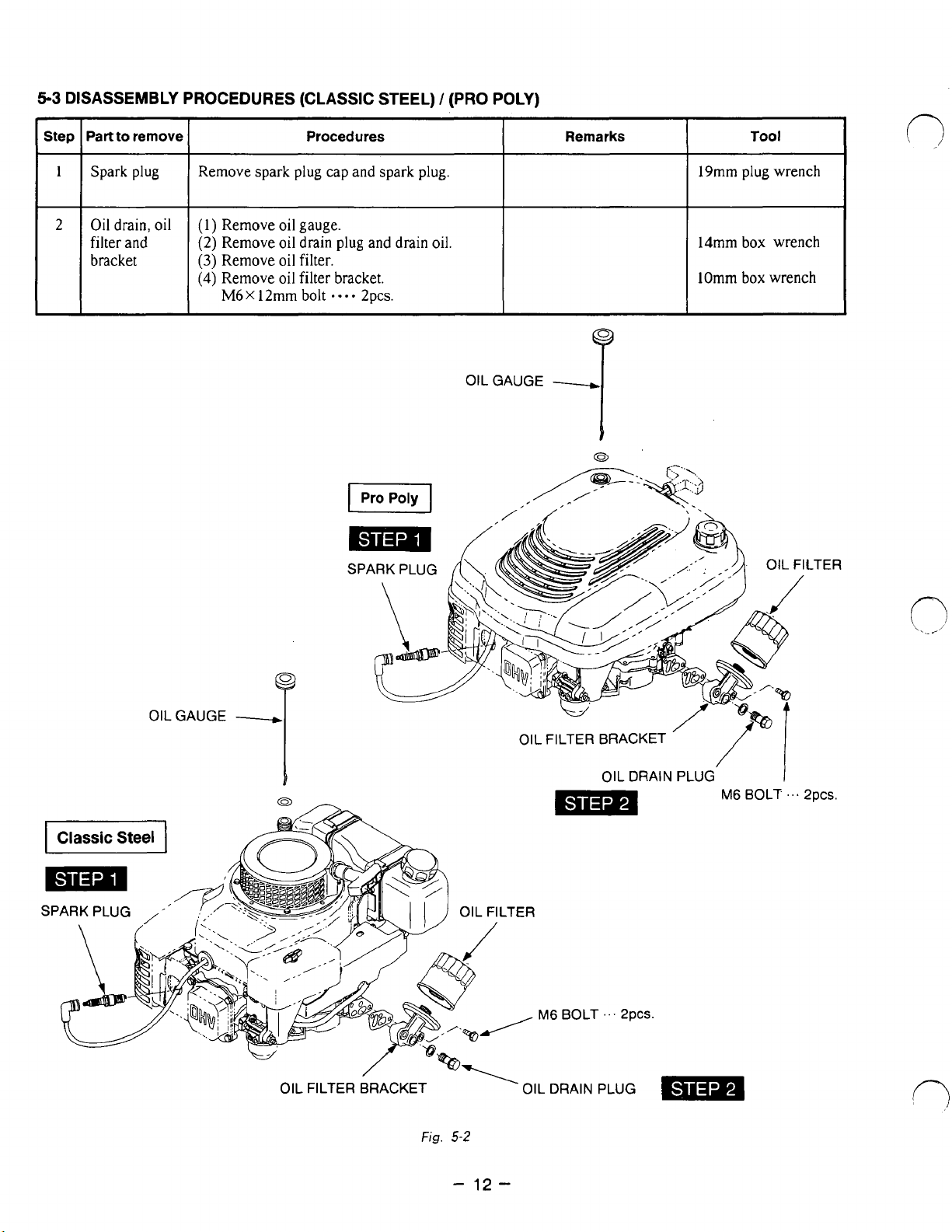
5-3
DISASSEMBLY PROCEDURES (CLASSIC STEEL) / (PRO POLY)
~~
Step
I
Part
to remove
Spark
plug
I
Remove spark plug cap and spark plug.
Procedures
'I
Oil
drain,
oil
(1)
filter
and
Remove
(2)
Remove
(3)
Remove oil filter. bracket
(4)
Remove
M6X
oil
gauge.
oil
drain
oil
filter bracket.
12mm
bolt
plug
....
and
2pcs.
drain
oil.
II
I
~~
Remarks
I
19mm
14mm box wrench
lOmm
Tool
plug wrench
box
wrench
OILGAUGE
y
T
OILGAUGE
p
T
SPARK PLUG LTER
OIL FILTER BRACKET
OIL DRAIN PLUG
'
M6
BOLT
'..
2pC~.
-
mm
SPARK PLUG
,
'
OIL FILTER BRACKET
Fig.
5-2
-
LTER
'
12-
OIL
~AC
clni
DRAIN
r
...
PLUG
gnrc
Page 17
5-3
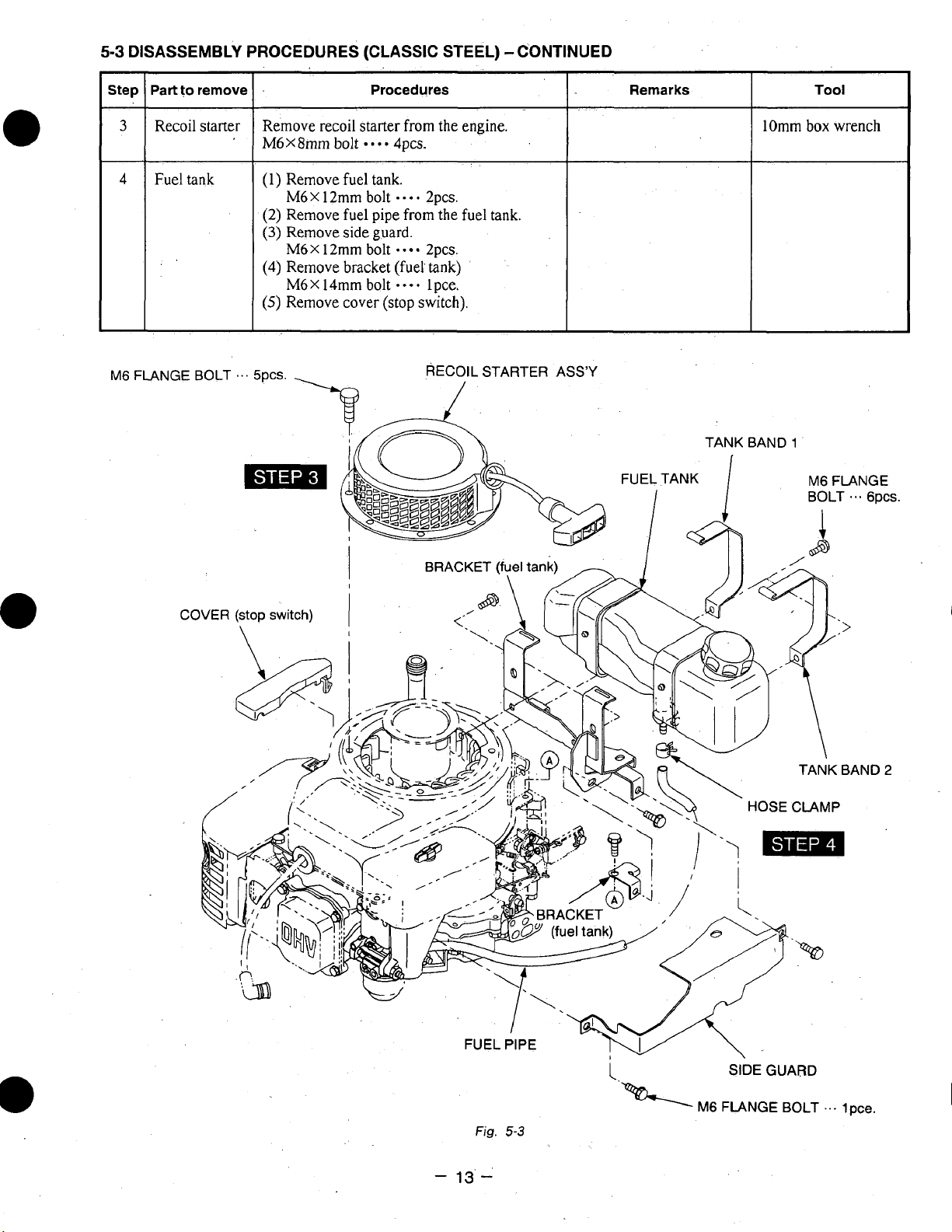
DISASSEMBLY PROCEDURES (CLASSIC STEEL) -CONTINUED
Part
to
remove
Procedures
Recoil starter
Fuel tank
M6
FL
Remove recoil starter from the engine.
M6X8mm
bolt
-0..
4pcs.
(1) Remove fuel tank.
M6X 12mm
bolt
.-**
2pcs.
(2) Remove fuel pipe from the fuel tank.
(3)
Remove side guard.
M6
X
12mm
bolt
*
-
Zpcs.
(4)
Remove bracket (fuel tank)
....
(stop
lpce.
switch).
RECOIL
STARTER
M6X 14mm bolt
(5)
Remove cover
ASS’Y
lOmm box wrench
M6
FLANGE
BOLT
-8-
GPCS.
COVER
(stop switch)
HOSE
CLAMP
-
Fig.
13’
I.
5-3
-’
M6
SIDE
GUARD
FLANGE
BOLT
. .
.
1
pce.
Page 18
5-3
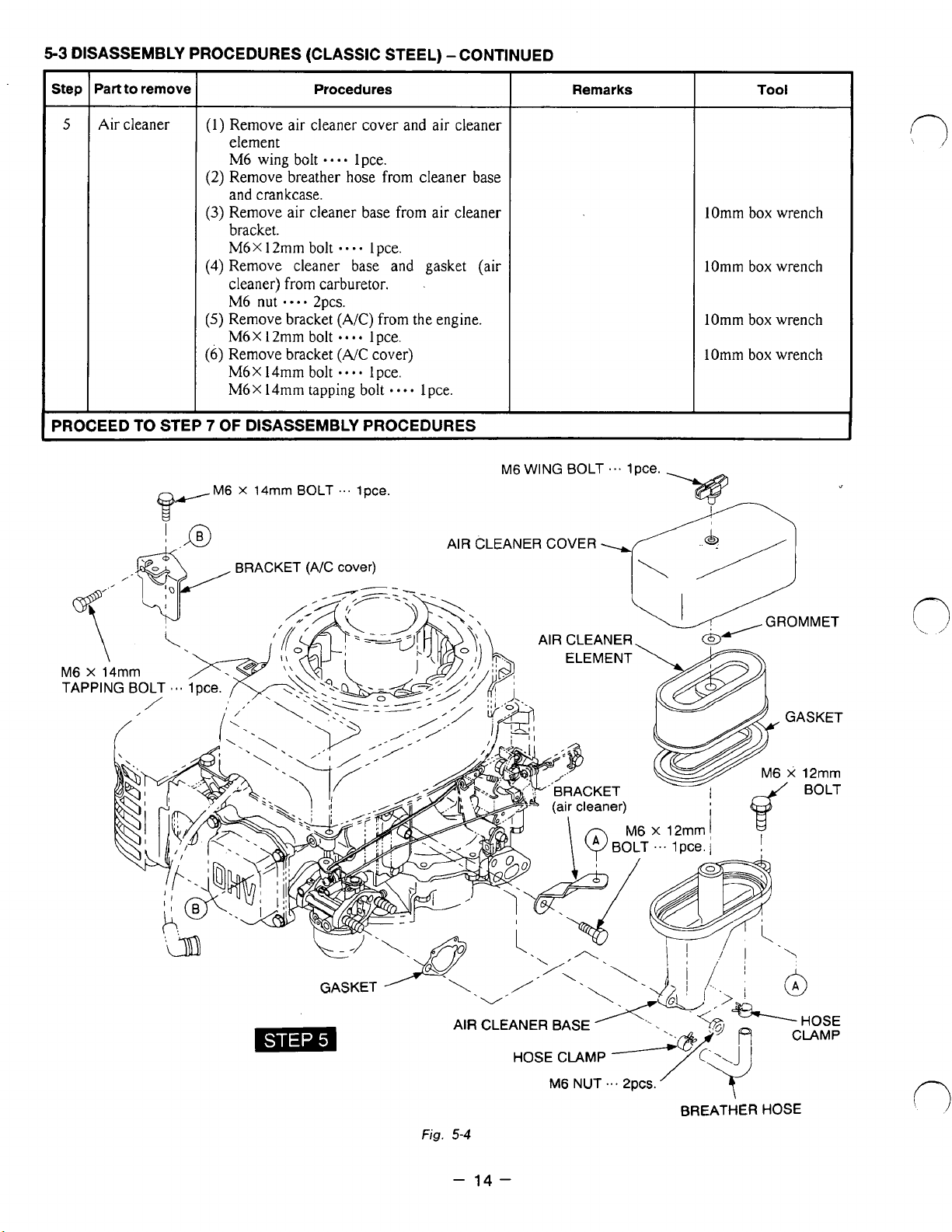
DISASSEMBLY PROCEDURES (CLASSIC STEEL) -CONTINUED
-
Part to remove
Step
Procedures
-
5
Air cleaner
(1) Remove air cleaner cover and air cleaner
element
M6 wing bolt
(2) Remove breather hose from cleaner
and crankcase.
(3)
Remove air cleaner base from air cleaner
bracket.
M6X12mm bolt
(4) Remove cleaner base and gasket (air
cleaner) from carburetor.
M6
nut
(5)
Remove bracket
M6X 12mm bolt
(6)
Remove bracket
M6
X
14mm bolt
M6x 14mm tapping
....
**--
.--.
2pcs.
(A/C)
....
(NC
lpce.
Ipce.
from the engine.
lpce.
cover)
-
1 pce.
bolt
....
lpce.
base
-
PROCEED TO STEP
7
OF DISASSEMBLY PROCEDURES
M6
X
14mm
BOLT
...
lpce.
M6
Remarks
WING BOLT
...
Ipce.
Tool
lOmm box wrench
lOmm
box wrench
lOmm box wrench
lOmm box wrench
M6 x 14mm
AIR
CLEANER
COVER
AIR CLEANER
AIR CLEANER BASE
HOSE
Fig.
5-4
-
14-
CLAMP
M6
NUT
...
~PCS.
BREATHER HOSE
Page 19
5-3
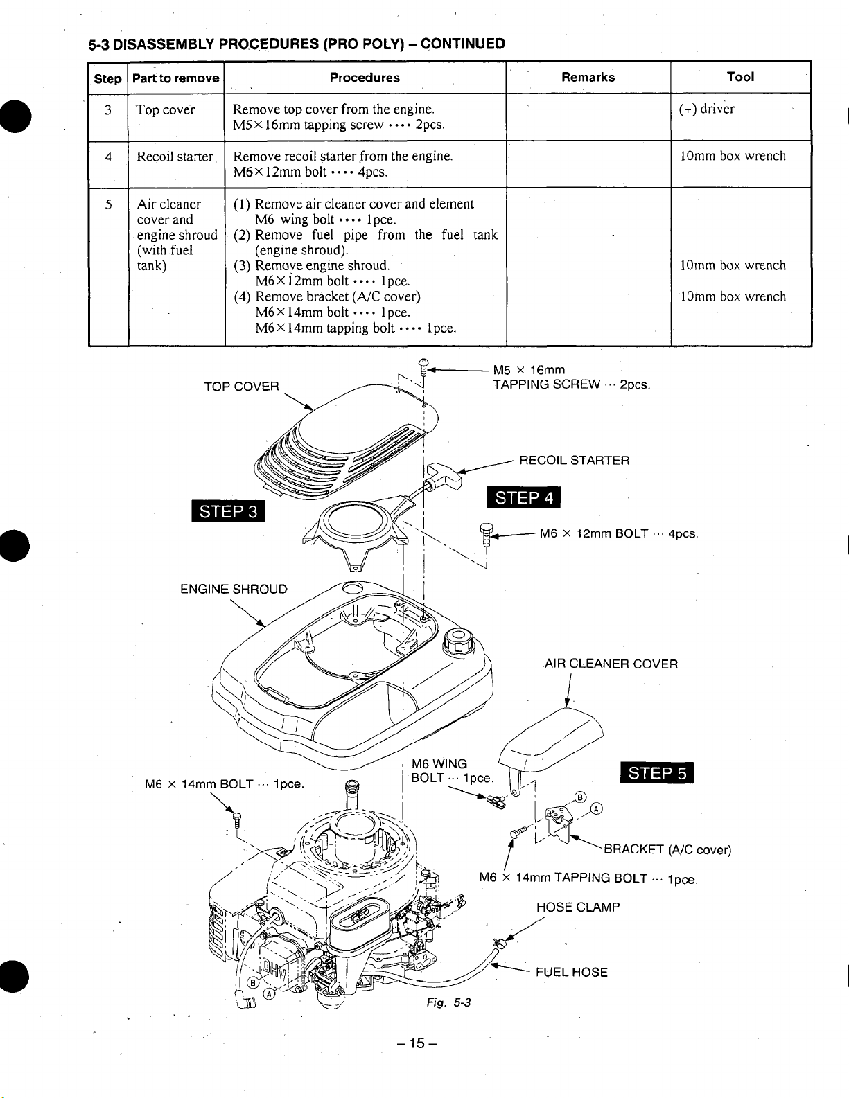
DISASSEMBLY PROCEDURES (PRO POLY) -CONTINUED
Part
to
Step
3
4
5
remove
Top cover
Recoil starter
Air
cleaner
cover and
engine shroud
(with fuel
tank)
L
TOP
Procedures
Remove top cover from the engine.
MSX 16mm tapping screw
Remove recoil starter from the engine.
M6
X
12mm bolt
(1)
Remove air cleaner cover and element
M6 wing bolt
(2) Remove fuel pipe
(engine shroud).
(3)
Remove engine shroud.
M6X 12mm
(4)
Remove bracket
M6X14mm bolt
M6X 14mm tapping bolt lpce.
COVER TAPPING SCREW
.
- -
90.-
bolt
-
-
4pcs.
1
pce.
from
....
lpce.
(NC
....
lpce.
. .
2pcs.
the
cover)
fuel
tank
Remarks
I
RECOIL STARTER
...
~PCS.
Tool
(+)
driver
lOmm box wrench
lOmm
box wrench
lOmm box wrench
M6
X
14mm BOLT
...
lpce.
X
12mm BOLT
AIR
CLEANER COVER
-
BRACKET (A/C
m TAPPING BOLT
...
.
.
4pcs.
.
1
pce.
cover)
-
15-
Page 20
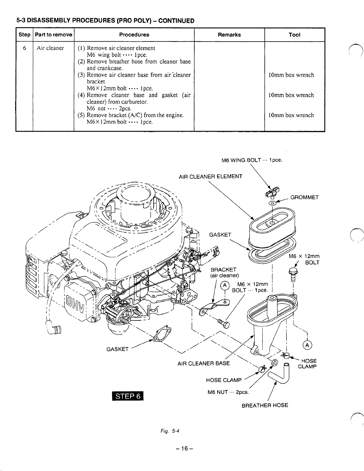
5-3
DISASSEMBLY
-
Step
Part to remove
-
6
Air
cleaner
PROCEDURES (PRO POLY) -CONTINUED
Procedures
(1)
Remove air cleaner element
bolt
....
M6 wing
(2)
Remove breather hose from cleaner base
and crankcase.
(3)
Remove air cleaner base from air-cleaner
bracket.
M6X12mm
(4)
Remove cleaner base and gasket
cleaner) from carburetor.
M6
nut
- -
(5)
Remove bracket
M6X12mm
lpce.
bolt
----
2pcs.
(AK)
bolt
....
lpce.
from
lpce.
the
(air
engine.
AIR
CLEANER ELEMENT
Remarks
M6
WING
BOLT
\
Tool
lOmm
box
wrench
lOmm
box
wrench
lOmm box wrench
'1.
1
pce.
r:
Fig.
5-4
-
16-
Page 21
5-3
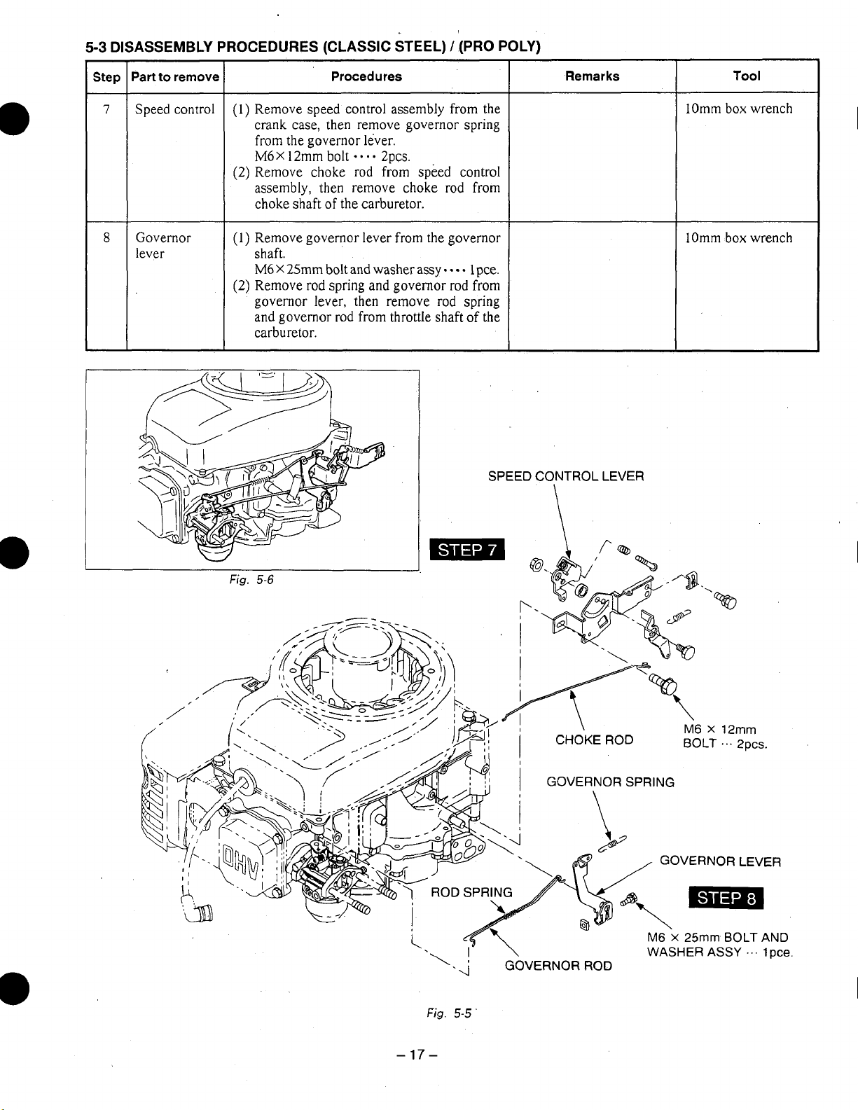
DISASSEMBLY PROCEDURES (CLASSIC STEEL) / (PRO POLY)
Step
r
'art
7
Speed control
Governor
8
lever
to
remove
Procedures
(1)
Remove speed control assembly from the
crank case, then remove governor spring
from the governor lever.
M6X
12mm bolt
(2)
Remove choke rod from speed control
assembly, then remove choke rod from
choke
shaft
(1)
Remove governor lever from the governor
shaft.
M6
X
25mm
(2)
Remove rod spring and governor
governor lever, then remove rod spring
and governor rod from throttle shaft of the
carburetor.
.-..
2pcs.
of
the carburetor.
bolt
and
washer
assy
- - -
rod
Remarks
1
pce.
from
SPEED CONTROL LEVER
Tool
lOmm box wrench
box
lOmm
wrench
W
Fig.
\
5-6
-
Fig.
17-
5-5
'
Page 22

Dart
to
remove
Procedures
Remarks
Tool
Carburetor
Muffler
M5 x 10mm
\
TAPPING
MUFFLER
(1)
Remove carburetor from
(2)
Remove gasket and insulator from stud
bolts.
(I)
Remove muffler cover from muffler.
M5X
lOmm
tapping screw
(2)
Remove muffler
M8
X70rnm
and
bolt and washer
stud
....
gasket.
bolts.
3pcs.
(muffler)
assy
-*..
M8
X
16mm
bolt and washer
assy
.*.-
SCREW
I
...
3pcs.
COVER
M8
x
16mm
Zpcs.
lpce.
BOLT AND
(+)
driver
12mm
box
wrench
Fig.
5-7
-
CARBURETOR
18-
Page 23

-
Step
Part
to
remove
Remarks Procedures
Tool
I
-
11
12
13
Oil
filler
Blower
hausing
Ignition coil
Remove the clamp from oil filler, and remove
oil filler bracket.
M6X
12mm
bolt
-
-
Ipce.
Remove the blower housing from the
crankcase.
M6x
12mm bolt
M6X
14mm bolt
(1)
Disconnect stop switch wire from
switch.
(2) Remove ignition coil
M6
X
30mm bolt
....
....
2pcs.
lpce.
-
-
-e
from
2pcs.
stop
crankcase.
I
Omm
box
lOmm
box
box
lOmm
wrench
wrench
wrench
-
19-
Page 24

Part
to
remove
Flywheel
I
(1)
Remove starter pully from flywheel
MI4
(2)
Remove flywheel from crankshaft.
(See
Fig.
(3)
Remove key from crankshaft.
nut
5-1
Procedures
Ipce.
1.)
I
Remarks
I
I
18mm
(-)
Tool
box
driver
I
wrench
STARTER
Fl
PULLEY
e
M14
&
NUT
'..
lpce.
KEY
\
Fig.
5-1
0
Fig.
5-9
-20-
Fig.
5-12
Page 25

Step
Part
to remove
Procedures
Remarks
Too
I
15
Brake
assy
(1)
Remove
M6
BRAKE
X
12mm
ASSY
\
brake
bolt
assy.
-
-
4pcs.
M6
x
12mm
lOmm
BOLT
...
box
4pcs.
wrench
-21
Fig.
-
5-13
Page 26

Step
Part
to remove
Procedures
Remarks
Tool
-
16
17
Cylinder
Cylinder
head
(1)
Remove cylinder baffle.
*.--
M6X8mm bolt
(1)
Remove rocker cover and guide plate
lpce.
from cylinder head.
M6
X
12mm bolt 4pcs.
(2)
Loosen lock nut for rocker arm adjusting
screw.
M8 lock nut
(3)
Slide
off
-
2pcs.
rocker arm shaft from the holder
to the flywheel side, remove rocker arms.
(See
Fig.
5-1
5.)
(4)
Remove push rods.
(5)
Remove cylinder head and gasket.
M8X65rnm
M8X40mm
M8 flangenut
bolt
bolt
2pcs.
.---
-....
lpce.
1
pce.
1 Omm box wrench
lOmm box wrench
12mm box wrench
12mm box wrench
Fig.
5-14
-22-
Fig.
5-15
Page 27

-
Step
'art to remove
-
18
Intake and
exhaust valve
19
Breather
-
INTAKE VALVE
EXHAUST VALVE
Procedures
(1)
Press down spring retainer and
slide
release from the groove of valve stem,
then remove spring retainer and valve
spring. (See Fig.
5-16.)
(2) Remove intake and exhaust valves
cylinder head.
(1)
Remove breather cover.
M6
X
12mm
bolt
.
2pcs.
Remove gasket (tappet cover), breather
plate and gasket (breather plate).
it
to
from
Remarks
Clean carbon and gum
deposits from the valves,
valve seats, ports and
guides. Inspect valves,
valve seats and guides.
Tool
lOmm box wrench
\\
COLLET
I
I
VALVE
RETAINER
SPRING
-23
Fig.
-
5-1
M6
x
12mm
BOLT
...
7
Fig.
5-1
6
2pcs.
/
Page 28

Part
to
remove Procedures
Remarks
Tool
Main bearing
cover (See
Oil
pump
(1)
Remove main bearing cover.
Fig.
5-18.)
M6X30mm bolt and washer
(1)
Remove
oil
pump cover from main bearing
cover.
M6
X
12mm bolt - 4pcs.
(2)
Remove
oil
pump (Inner) and
(Outer).
assy
*e*. 8~~s.
oil
pump
Do
not
lose
crankshaft.
spacer
for
lOmm box wrench
lOmm box wrench
OIL
PUMP
M6
COVER
x
12mm
I
BOLT
'.'
fi
4pcs.
Fig.
5-1
9
-24
-
Page 29

-
Step
22
-
Part
to
remove
Camshaft and
tappets
1
(1)
Remove camshaft from crankcase.
(See Fig.
(2)
Remove tappets from crankcase.
Procedures
5-20.)
Remarks
To
prevent the tappets
from
getting damages, put
the crankcase cylinder
down.
side
(See Fig.
Tappet
in
Mark tappets prior
moval to prevent error.
5-20.)
must
be
installed
their original position.
to
/,
/,
,/'
Tool
re-
I
f
I
TAPPET
CAMSHAFT
I
/'
B
I
I
Fig.
5-20
-25-
Page 30

Step
I
Part
to
23
I
remove
Connecting
rod and
piston
(1)
Remove connecting rod bolts and
connecting rod cap.
Connecting
(2) Turn crankshaft until piston
center,
assembly through
(3)
Remove
connecting
(4)Remove piston rings from piston.
Procedures
rod
bolt 2pcs.
push
out connecting
clips
and piston pin
rod
from piston.
L
24
I
(l).Tap
Crankshaft
lightly
on
flywheel end of crankshaft
to
remove from crankcase. (See Fig.5-22.)
top
of cylinder.
is
at top dead
rod
and piston
to
remove
I
I
Scrape off all carbon
deposits that might
interfere
piston
from
cylinder.
Remarks
with
removal
upper end
I
lOmm box wrench
of
of
Ring expander
Tool
Fig.
W
5-22
Fig.
5-23
-26-
M
0-
\
CONNECTING
SPACER
ROD
CAP
f-
Page 31

5-4
REASSEMBLY PROCEDURES
0
PRECAUTIONS
1)
Clean parts thoroughly’before reassembly.
.FOR
REASSEMBLY
Pay utmost attention to cleanliness of piston, cylinder, crankshaft, connecting rod and bearings.
2)
Scrape off all carbon deposits
3)
Check lip of oil seals. Replace oil seal if the lip
Apply
4)
Replace all the gaskets with new ones.
5)
Replace keys, pins, bolts, nuts, etc.,
6)
Torque bolts and nuts to specification referring to page
7)
Apply oil to rotating and sliding portions.
8)
Check and adjust clearances and end plays where specified in this manual.
oil
to the lip before reassembly.
from
cylinder head, piston top and piston ring grooves.
is
damaged.
if
necessary.
59
“12-2
TORQUE SPECIFICATIONS”
5-4-1
(1)
CRANKSHAFT
Install crankshaft on crankcase using an oil
seal guide to avoid damage to crankshaft
seal. (See
Fig.
5-24.)
oil
Fig.
5-24
-27
-
Page 32

5-4-2
(1)
PISTON AND PISTON RINGS
Install oil ring first, then second ring and top
ring. Spread ring only far enough
to
slip over
piston and into correct groove. Use care not to
distort ring. (See Fig.
5-26.)
Fig.
5-25
5-4-3
PISTON AND CONNECTING ROD
Install piston on connection rod.
Oil the small end of connecting rod before instal-
ling piston and piston pin.
Use
clips
on
both
side
of
the piston pin to secure
piston pin in position.
EN
ENDS
OF
PI
Fig.
Fig.
5-26
5-27
-28-
Page 33

5-4-4
(1)
CONNECTING
ROD
Before installing the piston and connecting rod
in
the cylinder, oil the piston, piston rings and
cylinder wall.
(2)
Stagger the piston ring gaps
the piston. (See Fig.
5-28.)
90”
apart around
Use a piston ring compressor when installing
piston.
Install piston and rod with the
flywheel side
(See
Fig.
(3)
Turn crankshaft
29.)
of
the crankcase.
to
bottom dead center, then tap
“MA”
marks
lightly top of the piston until large end
connecting
rod
meets crank
pin.
of
on
the
Fig.
5-28
(4)
Install connecting rod cap with the match mark
on
the main bearing cover side. (Match this
mark with the one
on
the left side
of
necting rod’s large end viewed from main
2
30)
pcs.
bearing cover side.) (See Fig.
Connecting rod bolt
-0.-
con-
PISTON
CONNECTING
CRANKCASE
RING
COMPRESSOR
ROD
Fig.
5-29
Tightening torque
17-20
170-200
12.2-14.5
Check for free movemont of connecting rod by
turning crankshaft
slowly.
N*m
kg-cm
ft4b
-29
-
Fig.
5-30
Page 34

5-4-5
(1)
(2)
TAPPET
AND
CAMSHAFT
Oil tappets and install in their original position.
in
Push
Lubricate bearing surfaces
Align timing mark
crankcase. (See
fully to avoid damage during camshaft installation.
of
camshaft.
on
crankshaft gear with timing mark
Fig.
5-31.)
on
camshaft and install camshaft
in
the
r'
Incorrect
valve
timing will cause engine's malfunction.
CAMSHAFT
Fig.
5-3
CRANKSHAFT
1
-
30
-
Page 35

5-4-6
(1)
ADJUST CRANKSHAFT END
PLAY
Adjust end play to the,specified values using the proper spacer.
The proper spacer. may be determined
R1
”7-
by
the following manner.
MAIN BEARING COVER
I,
I
Fig.
5-32
0
CRANKSHAFT END
(1)
Measure the depth “Al” (From the mating surface to the inner race
(2)
Measure the height
(A1+0.3)
-
Bl=SIDE CLEARANCE (mm)
(SIDE CLEARANCE)
(A+0.012)
-
Bl=SIDE
SIDE CLEARANCE
PLAY
“Bl”
(From the mating
-
0.2=THICKNESS OF CRANKSHAFT SHIM (mm)
to
the crank gear.)
CLEARANCE(in)
-
0.008=THICKNESS
OF
CRANKSHAFT
Following are available spacer shims.
1
SPACER
SHIMS
CRANKSHAFT
.
T=0.6
T=0.8
T=l
.O
mm
(0.024”)
mrn
(0.031”)
mrn
(0.039”)
~~ ~~
of
the ball bearing.)
SHIM
(in)
-
31
-
Page 36

5-4-7
(1)
MAIN
Install oil pump
M6
X
BEARING
to
the main bearing cover.
12mm bolt
8-9.5 N*m
80-1
00
6-7
COVER
....
4
pcs.
kgcm
ft*lb
CRANKCASE KEY
Lubricate the
faces. Add a light film of
bearing cover face
oil
seal and bearing sur-
to
hold the gasket in
oil
on the main
place.
Place spacers chosen at procedure 5-4-6
on crankshaft.
Use an oil seal guide when installing the
main bearing cover
to
avoid damaging the
seal.
Tap
the
cover into place with a soft hammer.
Main bearing cover.
M6
X
30
mm
bolt and washer
Tightening
8-9.5
80-1
00
6-7
torque
Nom
kgocm
ft*lb
-.-.
8
pcs.
CRANKSHAFT
OIL
0
RING
OIL
-32
PUMP
PUMP
-
(INNER)
COVER
M6
BOLT
".
~PCS.
Fig.
5-33
M6
BOLT
AND WASHER
ASS'Y
...
~Pcs.
Page 37

5-4-8
BREATHER VALVE
Attach breather plate (breather valve) and breather
cover
(See Fig.
Replace gaskets with new ones if they are torn
to
crankcase
5-34.)
using
proper gaskets.
or
damaged.
Replace breather hose at least once a year or when
ever
a
crack was found.
Fig.
5-34
5-4-9
(1)
CYLINDER HEAD
Clean carbon and gum deposits from the valves,
seats, ports and guides. Inspect
the
valve seats and valve guides.
(2)
Replace valves that are badly burned, pitted
warped.
(3)
When installing the valves
oil the valve stems and insert them
in
the cylinder head,
into
valve guide. Then place the cylinder head on a
flat table, install the washer, valve spring and
spring retainer. (See Fig.
(4)
Valve guides should be replaced when the
5-35.)
valve stem clearance exceeds specifications
“SERVICE DATA’
(See
page
57)
Draw the valve guides out and press the new
guides
Refer
in.
to
“SERVICE DATA”
for clearance specifications.
After replacing the valves and guides, lap
in
valves
around the face
place until a uniform ring
of
the valve. Clean valves and
wash cylinder head thoroughly.
(5)
Install cylinder head to cylinder with new head
gasket.
valves,
or
the
shows
INTAKE
VALVE
Fig.
5-35
r
When installing head gasket, show Fig.
Tighten three flange bolts and
in
evenly
three steps
by
the following tight-
5-36.
a
ening torque:
M8
X
65
Cylinder head
1
st
step
50
kgocrn
3.6
ft*lb
M8
X
40
M8
flange nut
Tightening
2nd
step
10
100
7.2
mm bolt
mm bolt
torque
N-m
kgocrn
ft-lb
...-
-.*-
. e.. .. ..
final
23-26
230-270
17-30
flange nut
2
pcs.
1
pce.
1
pce.
step
Nom
kgmn
ft*lb
-33-
Page 38

5-4-10
(1)
(2)
5-4-1 1 VALVE CLEARANCE ADJUSTMENT
(1)
(2)
ROCKER
ARMS AND PUSH RODS
Insert push rods into crankcase.
of
Put push rod tip in the hollow
Apply
oil
to
the
rocker arms and assemble them to the cylinder head using the rocker shaft and spacer.
tappet top.
Position the piston at the top dead center
obtained by placing the key
Loosen
the lock nut
on
slot
on
the power take off shaft
the rocker arm and turn
the rocker arm and the valve stem end. (See Fig.
Tighten the lock nut.
of
the compression stroke. The top dead center may
to
45"
Fig.
from the center
5-37
the
adjusting screw to adjust the clearance between
of
cylinder.
5-38.)
be
\
,'
0.085-0.1 15
-
[NOTE)
Check and adjust valve clearance with engine cold.
Check operation
Remeasure valve clearance.
(3)
Install guide plate and rocker cover using a gasket.
M6
X
12
mm bolt
of
valves
mm
by
turning crankshaft.
4
pcs.
-34-
Page 39

54-12
Install brake assy
M6
BRAKE
X
12
mm
ASSEMBLY
to
the engine.
bolt
.
4
80-
1
00
pcs.
kg-cm
Never apply
5-4-13
(1)
(2)
(31
FLYWHEEL
Put the woodruff key in the key way
shaft.
Wipe
off
tapered portion of the crankshaft and the flywheel center hole.
Pull the brake lever.
Install the flywheel to crankshaft.
Tighten the flywheel nut with the starter
pulley. (See Fig.
I
oil
or (grease) on the internal
MAGNETO
oil and de-grease thoroughly from the
5-39.)
Tightening torque
59-63
600-650
43-47
Nom
kgocrn
ft'lb
of
crank-
I-
of
flywheel and brake.
Fig.
RANKSHAFT
5-39
5-4-14
Install the ignition coil to the crankcase.
Adjust the air gap between the ignition coil and
the flywheel using a thickness gauge (filler gauge)
and tighten the bolts. (See Fig.
M6
IGNITION
X
30
mm
I
I
0.01
COIL
bolt
-
Air
gap
0.3-0.5
2-0.020
-
mm
2
in.
pcs.
5-40.)
I
I
-.35
-
Fig.
5-40
Page 40

5-4-15
BLOWER
HOUSING
AND
BRACKETS
Install blower hosing, oil filler bracket (fuel tank)
and air cleaner bracket.
M6
BOLT
x
12mm
...
lpce.
BLOWER
HOUSING
\
M6
x
BOLT
14mm
'.'
3PcS.
Classic
M6
M6
Pro
M6
M6 X 14
5-4-16
Steel
X
12
mm
X
14
mm
Poly
X
12
mm
mm
CYLINDER
bolt
bolt
bolt
bolt
-.
-
1
pce.
....
3
pcs.
-
2
pcs.
--e.
2 pcs.
BAFFLE
Install cylinder baffle.
M6
X
8
mm
54-17
OIL
FILLER
Install oil filler
M6
X
12
mm
5-4-18
CARBURETOR
bolt
to
the engine.
bolt
1
....
pce.
1
pce.
Install the gaskets, insulator and carburetor.
I
~~~
M6
BOLT
M6
x
x
12mm BOLT
14mm
...
2pCS.
TAPPING BOLT
Fig.
54 1 (Classic
...
2pcs.
\v
...
1
Dce
Steel)
M6
x
BOLT
J
14mm
...
2pcs.
ENGINE
SIDE.
GASKET 2 (INSULATOR)
CABURETOR
Fig.
542
I
-36-
\-
TAPPING BOLT
Fig.
5-41
(Pro
...
lorn.
Poly)
Page 41

5-4-19
(1)
.I
Attach the air cleaner gasket to the carburetor
flange when installing air cleaner base
engine. (See Fig.
(2)
(3)
AIR CLEANER
Install cleaner base
Tighten the clamp.for stop switch wire together w
M6
Nut
**..
Tightening torque
[NOTE]
Install cover and element to the air cleaner base.
M6
wing bolt lpce.
~PCS.
8-9.5
80-1
5-43.)
on
studs, install bracket, cleaner
N*m
00
kgcm
on
the
ith cleaner bracket
I
Connect a breather pipe between breather and air cleaner.
SLOW
MAIN
AIR
AIR
BLEED
BLEED
on
crankcase side.
JET
JET
Fig.
5-43
AIR
VENT
HOLE
5-4-20
GOVERNOR
ADJUSTMENT
For correct Carburetor throttle opening and gov-
ernor regulation, the governor lever must be properly adjusted.
(1)
Install throttle lever ,control linkage on governor lever and choke shaft control rod in
choke lever.
(2)
Hook
hole
Install bracket assembly
(3)
Install governor lever
spring from control lever hole
(B)
in governor lever as shown in Fig.
on
crankcase.
on
governor shaft but do
(A)
to the
5-44.
not tighten clamp screw.
(4)
Turn governor lever clockwise until throttle
valve.
in this position. (See Fig.
Check that governor lever clamp screw is loose
so
(5)
Insert a screwdriver in slot at end
in
carburetor
governor shaft
is
opened
fully.
5-45.)
can
be turned independently
Hold lever
of
governor
shaft. Turn clockwise as far as shaft can be
turned. Tighten governor lever clamp screw.
of
Fig.
5-44
-37-
Fig.
5-45
Page 42

5-4-21
(1)
MUFFLER AND MUFFLER COVER
Install muffler and muffler gasket.
M8
X
70
mm
bolt and washer assy
M8 X 16
mm
bolt and washer
Tightening torque
22.5-26.5
Nom
assy
.-..
2pcs.
..
..
lpce.
230-270
16.6-1 9.5
(2)
Install muffler cover
M5
X
10
mm
Tapping screw
5-4-22 FUEL
(1)
Install fuel tank bracket.
M6
(2)
Install fuel tank.
M6
(3)
Install side guard.
M6
X
X
X
12
12
12
TANK
mm
bolt
mm
bolt
mm
bolt
kgecrn
ft*lb
to
the muffler.
(if
applicable)
-.
- -
2pcs.
....
2pcs.
.
2pcs.
- -
3
pcs.
(4) Install cover (stop switch).
5-4-23
(1)
(2)
5-4-24
(1)
RECOIL
STARTER
AND
ENGINE
SHROUD
Install recoil starter and engine shroud.
M6
X
8
mm
bolt
--.e
4pcs.
Connect fueI pipe between fuel cock and carburetor.
OIL
FILTER BRACKET AND
OIL
FILTER
Install oil filter bracket
M6
X
12 mm bolt
-...
2pcs.
I
(2)
Tighten filter using a proper tool about 3/4 turn
Tightening torque
8-9.5
80-1
6-7
00
I
Nom
kgwn
ft*lb
after gasket contacts mounting surface
engine.
Check for leaks at test running after engine
is
assembly
completed.
of
-38-
OIL
FILTER
/
BRACKET OIL FILTER
Fig.
5-46
\
Page 43

5-4-25
(1)
SPARK
Install spark plug
Spark plug
PLUG
to
the cylinder head.
:
CHAMPION L86C
I
I
L
(2)
________~~~
New spark plug
1
1.8-1
4.7
120-1
8.7-1
0.9
Connect spark plug cap to the spark plug.
5-4-26 ENGINE
50
N-m
kgocm
ft*lb
Tightening
~~~
OIL
torque
Retightening
22.6-26.5 N*m
I
230-270
16.6-1
9.5
kg-cm
fblb
1
I
After complete reassembly, turn the engine over and pull the recoil starter
conditions or loose fitting parts.
Review and check wiring.
Fill crankcase with correct grade of oil. (See page
Crankcase oil capacity
5-4-27
(1)
(2)
CHOKE
AND
Start the engine. (Operate the engine without load.)
In order to fix the position
:
500cc
SPEED ADJUSTMENT
of
the speed control lever, insert a philips screw driver into the hole (A)
59,
"OIL
GRADE CHART
the speed control lever through the hole of the speed control bracket.
(3)
Loosen the adjusting screw on the speed control lever.
(4)
Check the engine speed by a tachometer or a revolution counter.
is
3350
Correct engine speed
(5)
Loosen the bolts
become
3350
r.p.m.
(B)
and (C), Move the speed control bracket to the position where the engine speed
r.p.m.
In order to reduce the engine speed move the speed control bracket -to the left.
(6)
After adjusting the engine speed, re-tighten the two bolts
(7)
Tighten the adjusting screw until it contacts the choke lever.
(B)
and
(C)
to
check for any abnormal
")
to
fix the bracket.
of
ROD
SPRING
B
CHOKE
\
\
LEVER
\
-39
A
SPEED
SCREW
n"L
When speed control bracket
in
the direction
Fig.
5-47
-
of
CONTROL
(PAN
the
arrow,.
LEVER
HEAD)
LOW
SPEED
is
moved
engine speed
is
reduced.
Page 44

5-5
BREAK-IN OPERATION
An
engine that has been completely overhauled by being fitted with a new piston, rings, valves and
connecting rod should be thoroughly
RUN-
IN
before being put back into service.
Good bearing surfaces and running clearances between the various parts can only be established
operating
the
engine under reduced speed and loads
for
a short period
of
time.
While the engine is being tested, check for oil leaks.
Make final carburetor adjustment and regulate the engine operating speed.
by
I
Steps
Step
Step
Step
Step
1
2
3
4
Load Engine speed Time
No
No
2.0
4.0
load
load
HP
HP
2500
3000
3000
3000
rpm
rpm
rpm
rpm
10
10
30
60
min
min
rnin
min
-
40-
Page 45

0
MAGNETO
6.
6-1
FLYWHEEL
".
MAGNETO
The ignition system of the
characteristic.
Being different from the breaker point type ignition system, this- system
troubles as starting-up failure due to dirty, burnt or corroded point surface. The electronic automatic
advancing ensures extremely easy starts and stable high performance at operating speed
ignition timing to the most suitable point.
6-2
BASIC
.
To
ensure the easy startability of the engine, the step advancing ignition timing system
the ignition coil. This system enables the engine to have basically two different ignition timings
according
1)At lower speed of the engine
Rotation of the flywheel induces current
transistor, it
As
the engine reaches the ignition timing, the ignition timing control circuit
is
activated and lets the current b flow through
This generates the collector current
IZ
because the power transistor is turned off.
This sudden current change generates a big voltage on the secondary side
sparks the spark plug.
2)At the higher engine speed
Rotation of the flywheel generates the current
power transistor, it is activated and the current
As
the
speed
collector current
transistor
This sudden current change generates a big voltage
sparks
The ignition timing control circuit for the higher engine speed is activated sooner than the control
circuit for the lower speed and not activated when the engine speed is in a lower range.
THEORY
to
the engine speed. Following are the explanation how the system works.
is
activated and the current
engine reaches the ignition timing, the ignition timing control circuit for the higher engine
is
activated and provides the base current
16
and will bypass the current
is
turned
at
the spark plug.
off.
EH18V
is a pointless flywheel magneto .with an autcmatic advancing
is
completely free from such
by
is
incorporated in
I,,
as this current flows through the base terminal
LZ
starts flowing.
for
the lower engine speed
the
base terminal of the power transistor.
L
which will bypass the current
11
as this current flows through the base terminal
12
starts flowing.
Is
to the power transistor. This current induces the
IL
to shut down
on
the secondary side of the ignition coil causing
the
11
and abruptly shut off the current
of
the ignition coil and which
current
IZ
abruptly because the power
advancing the
of
the power
of
the
-41
-
Page 46

(B.T.D.C.)
.
23"
4
I
F
ELECTRONIC ADVANCING FLYWHEEL
MAGNETO SYSTEM
1
STEP
ADVANCING
6-3
WIRING DIAGRAM
STANDARD
15.1
,
500
,
1000
ENGINE REVOLUTION
Fig.
,
2000
6-2
I
3000
(r.p.m.)
Stop
switch
Flywheel
Fig.
6-3
-42
-
Page 47

7.
AUTOMATIC
DECOMPRESSION
SYSTEM
The decompression system operates to release compression
The release lever mounted on the camshaft has a flyweight at one end and a crescent cam at the other
end. When starting the engine, the crescent cam juts out from the exhaust cam.
The exhaust tappet rides over the crescent cam opening the exhaust valve
CRESCENT CAM
EXHAUST CAM
Fig.
7-1
by
lifting
up
the exhaust valve at starting.
to
release compression.
LEVER
a
When the crank speed reaches a certain revolution, the flyweight
the centrifugal force turning the release lever to retract below the crescent cam. Thus the exhaust valve
closes allowing a sufficient compression for the engine to start
FLYWEIGHT
CRESCENT
CAM
Fig. 7-2
up.
of
the release lever moves outward
LEVER
by
-43-
Page 48

8.
CARBURETOR
8-1 OPERATION AND CONSTRUCTION
(See
Fig.
7-2.
and
SI.)
8-1 -1 FLOAT SYSTEM
The float chamber is located just below the carburetor body .and, with a float and a needle valve,
maintains a constant fuel level during engine operation.
The fuel flows from
chamber through needle valve. When the fuel rises
to a specific level, the float rises
buoyancy and fuel pressure are balanced, the needle
valve closes
fuel at the predetermined level.
to
shut off the fuel, thereby keeping the
the
fuel tank into the float
;
and when its
FLOAT
PILOT OUTLET
u
'\
Fig.
8-1
'
PILOT JET
Fig.
8-2
-44-
Page 49

8-1-2 PILOT SYSTEM
The pilot system feeds the fuel to the engine during idling and low-speed operation.
to
The fuel is fed through the main jet
by
the pilot air jet.
The fuel-air mixture is fed to the engine through the pilot outlet and the bypass.
At idling speed, the fuel is mainly fed from the pilot outlet.
8-1-3 MAIN SYSTEM
The main system feeds the fuel to the engine at medium- and high-speed operation.
The fuel
mixed with the fuel through the bleed holes in the main nozzle, and the mixture is atomized out
main bore. It
mixture, which
8-1
The
the negative pressure applied to the main nozzle increases and draws much fuel according1y;thus easily
start
8-2 DISASSEMBLY AND REASSEMBLY
Apart from mechanical failures, most of carburetor troubles are caused by an incorrect mixing ratio,
which may arise mainly due to a clogged up air or fuel passage in jets, or fuel level variations. In order
to assure proper flow
disassembly and reassembly procedures are as follows
is
metered by the main jet and fed to the main nozzle. The air metered by the main air jet is
is
mixed again with the air taken through the air cleaner into an optimum fuel-air
is
supplied to the engine.
-4
CHOKE
choke is used for easy start when engine is cold. When the starter is operated with a closed choke,
up
the engine.
of
air and fuel, the carburetor must be kept clean at all times. The carburetor
the pilot jet, where it is metered, and mixed with the air metered
of
the
:
(See Fig.
8-2.)
8-2-1 THROTTLE SYSTEM
(1)
Remove the philips screw
(14),
and pull out the throttle shaft(l3).
(2)
The spring
throttle stop screw
*
Exercise care not
8-2-2
(1)
(2)
8-2-3 PILOT SYSTEM
(1)
(2)
CHOKE SYSTEM
Remove the clip
pull out the choke shaft
When reassembling the choke shaft, make sure
that the cutout in the choke valve faces the main
air jet.
Remove the pilot jet
avoid damage to it.
Reassembly
Tighten the pilot jet securely. Otherwise, the fuel
may leak, causing engine malfunction.
(19)
can be taken out
(20).
to
(23)
(15)
and throttle valve
by
removing the
damage throttle valve ends.
and choke valve
(16).
(18),
using correct tool to
(17),
and
13
24
-
@-"--11
10
-
45
-
Fig.
8-3
Page 50

8-24
(1)
(2)
(3)
MAIN
Remove the bolt
From the body
Reassembly
a)Fasten the main jet securely
engine malfunction.
b) The bolt tightening torque
SYSTEM
(11)
(3)
remove the main jet
and take out float chamber body
is
(5).
(9).
to
the body. Otherwise, the fuel may become too rich and cause
80
kg-cm.
8-2-5
(1)
When cIeaning the jets, use neither a drill nor a wire (because of possible damage to the
orifice which will adversely affect fuel flow). Be sure to use compressed air
(2)
FLOAT
Pull out the float pin
When removing the needle valve and floats, gently tap the reverse side using the rod more slender
than the float pin and remove, since the float pin is calked
SYSTEM
(8)
and remove the float
(7)
and needle valve
to
(6).
to blow them clean.
the carburetor body.
-
-46
n
-
Page 51

9.
STARTING
9-1
RECOIL
STARTER
SYSTEM
When repairing recoil starter, disassemble and reassemble in the following procedures.
Tools: Socket wrench, Needle nose pliers, Screw driver
9-1-1
HOW
(1)
Remove recoil starter from engine.
(2)
Pull starter knob and pull out starter rope for
30-40cm
TO
DISASSEMBLY
to line up notch
on
reel with outlet
hole for starter rope.
Hold reel with thumb and pull starter rope
inside the starter case with screw driver.
(See Fig.
9-1
or
9-2.)
Rewind reel clockwise until the rotation stops.
When rewinding the reel, control the rotation
by
holding starter rope
using
the notch
on
the
reel and pressing the reel with thumb.
(3)
Remove parts in the following order.
1.
Return spring
2.
Rachet
3.
Friction spring
4.
Rachet guide
5.
Set screw
Fig.
9-1
0-3
(Classic
Steel)
-47-
STARTER
ROPE
Fig.
-3
&--"
9-2 (Pro
4
Poly)
Page 52

(4)
Remove the reel from the starter case as shown
Fig.
in
9-3.
Take out the reel slowly turning it lightly
to
towards the left and right
from the hook.
Do
not remove the reel quickly
remove spring
or the spring may escape from the starter case.
Untie the starter rope from the knob and remove.
STARTER CASE
9-1-2
(1)
HOW
Put
and tie it
TO
REASSEMBLE
the starter rope through the starter knob
as
shown in Fig.
tightly for the safety sake.)
Put the opposite side
of
starter case and reel. Tie
the starter knob end and put the
completely.
9-4.
(Tie the rope
the rope through the
it
in the same way
knot
in the reel
as
L
Pro
Poly
STARTERCASE
Fig.
9-3
Fig.
9-4
(2)
Check that the spring is securely set in the reel.
Adjust
so
the position
of
inner end
of
the spring
it hooks on hook in the starter case securely.
The shape of starter spring inner end may be
adjusted with
a
plier
if
necessary.
I
I
INNER
-48-
END
OF SPRING
OUTER END
/
'
Fig.
9-5
SPRING KEEPER
BEARING
OF
REEL
SPRING
Page 53

(3)
Prior to installing the reel in the starter case,
wind
the starter rope in the reel for
2.5
the arrowhead direction as shown in Fig.
Then let the rope out
of
the reel from the reel
notch. Line, up the reel hook with the inner end
of the spring and install the reel in the starter
case.
is
Check that the inner end of spring
securely
hooked onto the hook.
turns in
9-6.
Fig.
9-6
(4)
Reassemble the parts in reverse order of disassembly.
I
Check that the ratchets are pushed
ratchet springs toward the center
of
the recoil.
Install the friction plate with its two bosses set
inside of the bent portion
Apply small amount of lock-tight
of
ratchets.
to
the center
screw and torque it.
Thightening
3.9
4.0
2.9
(5)
Hold starter rope as shown
turn reel
4
torque
Nom
kg*crn
ft4b
times
in
in
Fig.
the
arrowhead direction.
9-8
Firmly press the reel not to allow reverse turn
and pull starting knob to
let
starter rope out
starter case.
Return knob slowly to let starter rope rewind
in
reel.
by
the
and
of
I
Classic
C~-FRICTION
&-SET
Steel
-RATCHET GUIOE
SPRING
SCREW
Fig.
9-7
Pro
Poly
0-FRICTION
“RATCHET GUIDE
Pro
SPRING
SET
SCREW
Poly
-49-
Fig.
9-8
Page 54

(6)
Test the operation
project and retract properly. Mount the recoil starter
(7)
If the spring escapes from the reel when disassembling the recoil, hook the outer end of the spring
onto
the
notch
(8)
Lubricate the rotating parts, sliding parts and spring with heat resistant grease or mobile oil when
of
the recoil starter to see if the rope recoils satisfactorily and the ratchets
to
the engine.
of
the reel and rewind the spring into the housing.
reassembling the recoil and prior to long term storage.
-50-
Page 55

a
IO.
TROUBLESHOOTING
The following three conditions must be fulfilled for satisfactory engine start.
1.
The cylinder filled with a proper fuel-air mixture.
2.
Good compression in the cylinder.
3.
Good spark, properly timed, to ignite the mixture.
The engine cannot be started unless these three conditions are met. There
make engine start difficult,
a high back pressure due to a long exhaust pipe.
The most common causes of engine troubles are given below:
10-1
STARTING DIFFICULTIES
e.
g.,
a heavy load on the engine when it is about to start at low speed, and
are
also other factors which
10-1-1
(1)
(2)
(3)
(4)
(5)
(6)
10-1-2
If starting difficulties and loss of power are not due to the fuel system or ignition system, the
following must be checked for possible lack of compression.
(1)
(2)
(3)
(4)
FUEL
No
gasoline in the fuel tank ; or the fuel cock closed.
The carburetor
Water, dust or gum in the gasoline interfering the fuel flow to the Carburetor.
Inferior grade gasoline or poor quality gasoline is not vaporized enough to produce the correct
fuel-air mixture.
The carburetor needle valve is held open by dirt
flows out
This trouble may be remedied, depending
grip of a screwdriver or the like.
If the carburetor overflows, excessive fuel runs into the cylinder when starting the engine, making
the fuel-air mixture too rich
pulley a few turns in order to let the rich fuel-air mixture out of the spark plug hole into the
atmosphere. Keep the carburetor choke open during this operation. Dry the spark plug well, screw
it into place, and try to start again.
COMPRESSION SYSTEM
Engine inside is completely dried up because
Loose or broken spark plug. This causes a hissing noise made by mixture gas running out
cylinder in compression stroke during cranking.
Damaged head gasket or loose cylinder head. A similar hissing noise
sion stroke.
Incorrect valve clearance
If the correct compression is not obtained even after remedying the above, disassemble the engine
and check further as follows:
a) Valve stuck open due to carbon or gum on the valve stem.
b)
If
the piston rings are stuck on the piston, remove the piston and connecting rod from the engine.
Clean or replace the parts.
SYSTEM
is
not choked sufficiently, especially when the engine is cold.
of
the carburetor when the engine
to
burn. If this happens, remove the spark plug, and turn the starting
or
gum. This trouble can
is
idling. (Overflow)
on
cases, by lightly tapping
of
a
long period
of
storage.
is
be
detected as the fuel
the
float chamber with the
produced during compres-
of
-51
-
Page 56

10-1-3
Check the followings for lack of spark
(1)
(2)
(3)
(4)
(5)
(6)
(7)
10-2
(1)
(2)
(3)
(4)
(5)
(6)
10-3
(1)
(2)
(3)
(4)
(5)
(6)
IGNITION SYSTEM
.
Leads
Ignition coil damaged and shorted.
Spark plug cable wet or soaked with oil.
Spark plug dirty or wet.
Spark
Spark plug electrodes are connected or bridged.
Incorrect spark timing.
Incorrect spark plug electrode gap. Adjust it
Ignition cable worn and leaking.
Sparks weak.
Ignition wire connections loose.
Water in gasoline.
Insufficient compression.
Fuel tank empty. Water, dirt, gum, etc. in gasoline.
Vapor lock,
Vapor lock in the fuel lines or carburetor due to the use
Air vent hole in the fuel tank cap plugged.
Bearing parts seized due to lack of oil.
Magneto or ignition coil faulty.
of
the ignition coil or spark plug.
plug electrode gap incorrect.
ENGINE MISFIRES
ENGINE
STOPS
i.
e., gasoline evaporating
to
anywhere between
in
the fuel lines due to overheat around the engine.
0.7
and 0.8mm.
of
too volatile winter gas in the hot season.
10-4
ENGINE OVERHEATS
(1)
Crankcase oil level low. Add oil immediately.
(2)
Spark timing incorrect.
(3)
Low
grade gasoline is used, or engine
(4)
Cooling air circulation restricted.
(5)
Cooling air path misdirected causes loss
(6)
Cylinder head cooling fins clogged up with dirt.
(7)
Engine operated
(8)
Exhaust gas discharge restricted, or carbon deposits in the combustion chamber.
(9)
Engine running
in
an enclosed space without sufficient cooling air.
on
low- octane gasoline detonates due to heavy load
is
overloaded.
of
cooling efficiency.
at
low speed.
-
52
-
Page 57

10-5
(1)
(2)
(3)
(4)
(5)
(6)
(7)
10-6
(1)
(2)
(3)
(4)
ENGINE KNOCKS
Poor quality gasoline.
Engine operating under heavy load
Carbon or lead deposits
in
the cylinder head.
at
low speed.
I.
Spark timing incorrect.
Loose connecting rod bearing due to wear.
Loose
piston pin due to wear.
Engine overheated.,
ENGINE BACKFIRES THROUGH CARBURETOR
Water
or
dirt in gasoline,
or
low-grade gasoline.
Intake valve stuck.
Valves overheated, or hot carbon particles in the combustion chamber.
Engine cold.
-
53
-
Page 58

11.
INSTALLATION
Engine life, ease of maintenance and inspection, frequency
is
all depend on the way in which the engine
installing the engine.
11
-1
INSTALLING
When mounting the engine, carefully examine its position, the method of connecting it to a machine,
the foundation, and the method of supporting the engine.
When determining its mounting position,, in particular, make sure that gasoline and oil can easily be
supplied and checked, the spark plug can easily be checked, the air cleaner can easily be serviced, and
that the oil can easily be discharged.
11-2
VENTILATION
Fresh air is necessary for cooling the engine and burning the fuel.
the
a
engine
duct
In the case
can cause vapor lock, oil deterioration, increased oil consumption,
shorter engine life, etc., making it impossible to operate the engine properly.
to provide
for engine cooling, and temperature rise
Keep the engine room temperature below
or
is
operated under a hood or in a small room, temperature rise in the engine room
baffle
to
guide cooling air to the engine to prevent recirculation of the hot air used
installed. Carefully observe the following instructions for
of
the machine.
50°C
even in the hottest period of the year.
of
checks and repairs, and operating cost
loss
of
power, piston seizure,
It
is necessary, therefore,
11-3
EXHAUST GAS DISCHARGE
Exhaust gas is noxious. When operating the engine indoors, be sure to discharge the exhaust gas
outdoors. If a long exhaust pipe is used in such a case, the internal resistance increases causing loss
engine power. Thus pipe inside diameter must be increased in proportion to exhaust pipe length.
3m
Exhaust pipe: Less than
Less than
long, pipe inside diameter
5m
long, pipe inside diameter
25
30
mm,
mm.
of
-54-
Page 59

12.
SERVICE
DATA
“STD”
Whereas, “Limit” shows the maximum allowance
If
12-1
in the following table is the parts dimension from the brand new engine
for
the parts
the measurement exceeds beyond the “Limit”, the part needs
CLEARANCE
‘DATA
AND
LIMITS
ITEM
CYLINDER
0
Valve
HEAD
seat contact width
IN. EX.
or
the spare parts.
to
be used
to
be replaced and/or repaired.
on
the engine.
STD
LESS
THAN
0.05
(0.002)
0.7
-
1
.O
(0.028 - 0.039)
Unit : rnm
Limit
0.1
(0.004)
2.0
(0.079)
(in)
Valve
guide inside dia.
5.500 - 5.51
(0.21 65 - 0.21 72)
8
5.65
(0.2224)
-55-
Page 60

Unit
:
mm
(ir
CYLINDER
0
Inside dia.
0
Roundiness after reboring
ITEM
STD
1
st
reboring
2nd
reboring
T
STD
67.000 - 67.01 9
(2.6378
67.250
(2.6476
67.500
(2.6575
LESS
0.01
(0.004)
-
2.6385)
-
67.269
-
2.6484)
-
67.51 9
-
2.6582)
THAN
Lmit
To
be rebored when the
difference between max. and
min.
of
diameter reached to 0.1
(0.004).
Ditto
0
Cylindricity after reboring.
PISTON
0
Piston size (At skirt in thrust
direction)
STD
1
St
2nd
Q/S
01s
LESS
0.015
(0.0006)
66.96
(2.6362
67.21
(2.6461
67.46
(2.6559
THAN
-
66.98
-
2.6370)
-
67.23
-
2.6469)
-
67.48
-
2.6567)
66.87
(2.6327)
67.1 2
(2.6425)
67.37
(2.6524)
-56
-
Page 61

Uni
:
mm
(in)
ITEM
0
Ring groove side clearance
0
Piston pin
0
Piston pin outside dia.
hole
I
t
TOP
2nd
Oil ring
T
I
"
"
"
STD
0.050
-
0.095
(0.001 9
(0.001 6
(0.5508
(0.5508
-
0.0037)
-
0.040
13.991
13.992 - 14.000
0.085
-
0.0030)
0
-
0.035
(0
-
0.001 4)
-
14.002
-
0.551
-
0.551 2)
3)
Limit
(0.006)
(0.006)
2
0.1
(0.006)
14.035
(0.631
3)
13.960
(0.6284)
Clearance between piston and
cylinder at skirt area.
0
Piston ring end gap
TOP
2nd
oil ring
'
(0.0008
(0.01 18
0.020
-
-
0.05
-
(0.0020
0.3
-
-
0.059
0.0023)
0.25
-
0.098)
0.9
0.0354)
0.23
(0.01
0)
1.3
(0.0091)
2.1
(0.0591)
-
57-
Page 62

Unit
:
rnm
(in)
CONNECTING
0
Big end inside dia.
0
Clearance between big end
and crankpin
0
Small
end inside dia.
0
Clearance between small end
and piston pin
ROD
ITEM
STD
26.000 - 26.01 3
(1.0236
(0.001
14.01
(0.551 6
0.037
-
-
5
-
0
-
-
1.0241)
0.063
0.0024)
14.021
0.5520)
Limit
26.1
(1.1 850)
0.2
(0.008)
14.08
(06331)
0
Big end side clearance
CRANKSHAFT
0
Journal dia.
0.01
0
-
0.029
(0.0004 - 0.001
-
0.3
0.1
-
(0.0039
25.950
(1.0217
24.988
(0.9838
0.01
-
25.963
-
1.0221)
Dl, D2
-
24.997
-
0.9841)
1)
18)
0.1 2
(0.0047)
0.5
(0.040)
25.84
(1.1 752)
-58-
Page 63

Unit:
mm
~
(ir
CAMSHAFT
0
Cam height
0
Journal
"D"
outside dia.
type
VALVE
0
Valve stem outside dia.
ITEM
~
IN.EX.
CAMS
Dl
D2
IN.
STD
-
29.8
29.6
(1.165-1.173)
-
16.973
(0.6682
14.973
(0.5895
5.440
(0.21 42 - 0.21 48)
16.984
-
0.6687)
-
14.984.
-
0.5899)
-
5.455
Limit
29.45
(1.159)
16.95
(0.6673)
14.95
(0.5886)
5.35
(0.21 06)
0
Clearance between valve stem dia.
and valve guide
0
Valve clearance
EX.
IN.
EX.
IN./EX.
(cold)
5.426
(0.21 36
0.045
(0.0018
0.056
(0.0022
0.085
(0.0033
-
5.444
-
0.21 43)
-
0.078
-
0.0031)
-
0.092
-
0.0036)
-
0.1 15
-
0.0045)
5.35
(0.21 06)
0.3
(0.01 2)
0.3
(0.01 2)
-59-
Page 64

Unit
:
mm
~~
(in).
TAPPET
0
Stem outside dia.
Guide inside dia.
0
Tappet guide clearance
ITEM
8
STD
7.960 - 7.975
(0.31 34
(0.31
(0.001
-
0.3140)
8.000
-
8.01
50
-
0.31
0.025 - 0.055
0
-
0.0022)
Limit
5
56)
ROCKER
0
Rocker shaft outside dia.
0
Rocker
VALVE SPRING FREE LENGTH
ARM
arm
shaft clearance
11.995 - 12.000
(0.4722
12.01
(0.4731
(0.0006
6 - 12.034
6 - 0.039
0.01
-
0.4724)
-
0.4738)
-
0.001
5)
11.92
(0.4693)
0
-60-
Page 65

Unit
:
mm
(in)
0
Valve cutter angle(a)
0
Valve contact width(b)
12-2
TORQUE SPECIFICATIONS
DESCRIPTION
Cylinder head bolts
Connecting rod cap bolts
ITEM
STD
a:
90"
:
0.7
-
1
b
a
kg
cm
,
170
-200
.O
(0.028
-
0.039)
TIGHTENING TORQUE
N*m
-
19.6
Limit
2.0
(0.079)
16.6
12.2
ft=
Ib
-
19.5 22.5 - 26.5 230 - 270
-.
14.4 16.6
Flywheel nut
Main bearing cover bolts
Spark plug
12-3
OIL
GRADE CHART
Single
Lubricant
Quality
grade
New
spark plug
Retightening
I
58.8
-
63.7 600 - 650
-
100
120- 150
Recommended oil viscosity for the embient temparature
I
5w
-
20
-4
I
1
I
T
10
w
20
w
##
20
low-30
I
-
10
14
0
32
10
50
I
I
I
I
I
20
68
#
30
I
30
86
1
I
43 - 47
5.7
-
8.7
-
-
16.6
I
I
I
I
40
104
7.2 7.8 - 9.8 80
10.9 11.8-14.7
19.5 22.6 - 26.5 230 - 270
1
"C
"F
1
1
Use
oil
classified
Multi-grade oil tends to increase its consumption at
as
SC
or
higher.
-
61
high
-
ambient temperature.
Page 66

13.
MAINTENANCE AND STORAGE
The following maintenance jobs apply when the engine is operated correctly under normal conditions.
The indicated maintenance intervals are by no means guarantee maintenance free operations during
these intervals.
For example, if the engine is operated in extremely dusty conditions, the air cleaner should be cleaned
every day instead
13-1
DAILY MAINTENANCE (EVERY
of
every
50
hours.
8
HRS.)
MAINTENANCE
1)Clean away dust and chaff from engine.
2)Check fuel leakage from fuel system.
any, retighten fasteners or replace
necessary parts.
3)
Inspect for loose hardware and
retighten if necessary.
4)
Check oil level and add to full mark.
13-2 INITIAL
I
1)Change crankcase oil.
20
HOURS.
MAINTENANCE
MAINTENANCE
REMARKS
Governor linkage is especially sensitive Read instruction for
to dust.
If
Loose bolts and nuts may come
result in breakage of other parts.
off
I
and
I
To
remove sludge from run-in operation.
REFER
use.
Read instruction for
use.
Read instruction for
use.
Read instruction for
use.
REFER REMARKS
Read instruction for
I
13-3 EVERY
1)Change crankcase oil.
2) Clean air cleaner.
50
HOURS.
MAINTENANCE
I
3)Check and clean spark plug.
4)
Clean cooling system.
(10 DAYS) MAINTENANCE
Contaminated oil quickens wear.
If dirty, wash in gasoline or polish with
emery paper.
-
62
-
REFER REMARKS
Read instruction for
use.
Read instruction for
1
use.
Read instruction for
1
use.
Read instruction for
use.
Page 67

13-4
EVERY
100-200
HOURS. (MONTHLY) MAINTENANCE
MAINTENANCE
REFER
REMARKS
1)
Inspect cooling system and remove dirt
Consult
your nearest
Remove blower housing and clean up
and chaff.
Robin
dearer.
between fins and housing.
I
2)Clean and adjust spark plug gap.
Read instruction for
I
use.
3)
Change,
oil
filter.
Read
instruction
for
use.
13-5 EVERY 500-600 HOURS. MAINTENANCE
MAINTENANCE
I
REMARKS
I
REFER
I
1)
Remove carbon from cylinder head.
Carbon deposits
in
combustion chamber
Consult your nearest
causes lack of power.
Robin dearer.
2)
Disassemble and clean carburetor.
Consult
your nearest
Robin dearer.
I
3)
Clean fuel tank.
Consult your nearest
Robin dearer.
I
4)Adjust valve clearance.
I
Consult your nearest
Robin
dearer.
I
5)
Replace spark plug.
Consult
your
nearest
Robin
dearer.
6)Overhaul engine
Consult your nearest
Robin dearer.
I
13-6 EVERY
1000
HOURS.
(YEARLY) MAINTENANCE
MAINTENANCE
REFER
REMARKS
1)
Replace fuel lines once a year.
,
Robin
dearer.
Avoid hazards caused by fuel leakage.
Consult
your
nearest
13-7
ENGINE STORAGE
(1)
Perform the above
13-1
and
13-2
maintenance
jobs.
(2)
Drain fuel from the fuel tank and carburetor float chamber.
(3)
To
prevent rust in the cylinder bore, apply oil through the spark plug hole and turn the crankshaft
(4)
Turn the starting pulley
by
hand and leave it where the resistance is the heaviest.
(5)
Clean outside
of
the engine with oiled cloth.
(6)
Put a plastic cover or the like over the engine and store the engine in dry place.
several turns by hand. Reinstall the plug.
.
-
63
-
Page 68

Industrial
Engines
 Loading...