

Page 1
© 2017 Robertshaw Climate 844-362-4822 Page 1 250037-01
PHANTOM WIRE™
RS-PWIRE
Installation Instructions
DESCRIPTION
The RS-PWIRE Phantom Wire™ device allows the installer to connect any thermostat when a ‘common’ wire is not
available in the existing thermostat cable. This handy device ‘creates’ a phantom wire. In many existing installations,
older thermostat cables don’t have a common (24VAC common) wire because they were not needed for the
mechanical thermostats originally installed. Years ago, it was typical for the cable to only have four (4) conductors.
The RS-PWIRE creates the ‘common’ wire so the HVAC unit can be used along with any thermostat requiring a 24VAC
common. Additionally, the RS-PWIRE includes screwless terminals, color-coded wiring for the HVAC unit connection,
and LEDs on the unit to show power, heat, cool and fan calls are being created from the thermostat, practically
eliminating troubleshooting.
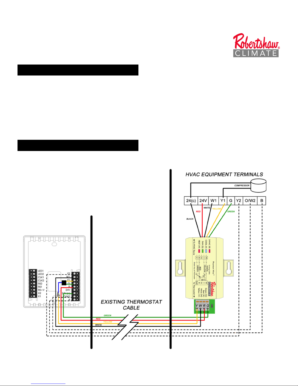
DRAWING
Page 2
© 2017 Robertshaw Climate 844-362-4822 Page 2 250037-01
INSTALLATION & WIRING
AT HVAC EQUIPMENT LOCATION
1) Turn off power for HVAC unit
2) Remove cover to HVAC control board
3) Remove existing thermostat cable, but leave 2-wire compressor leads in place (will be
connected to Y and C)
AT THERMOSTAT LOCATION
4) Remove existing thermostat
5) Install thermostat base
6) Install Diode Assembly to Y and G terminals
a. White to W terminal
b. Yellow to Blue diode assembly with wire nut
c. Red to R terminal
d. Green to 24(c) terminal
7) Install thermostat on backplate
AT HVAC EQUIPMENT LOCATION
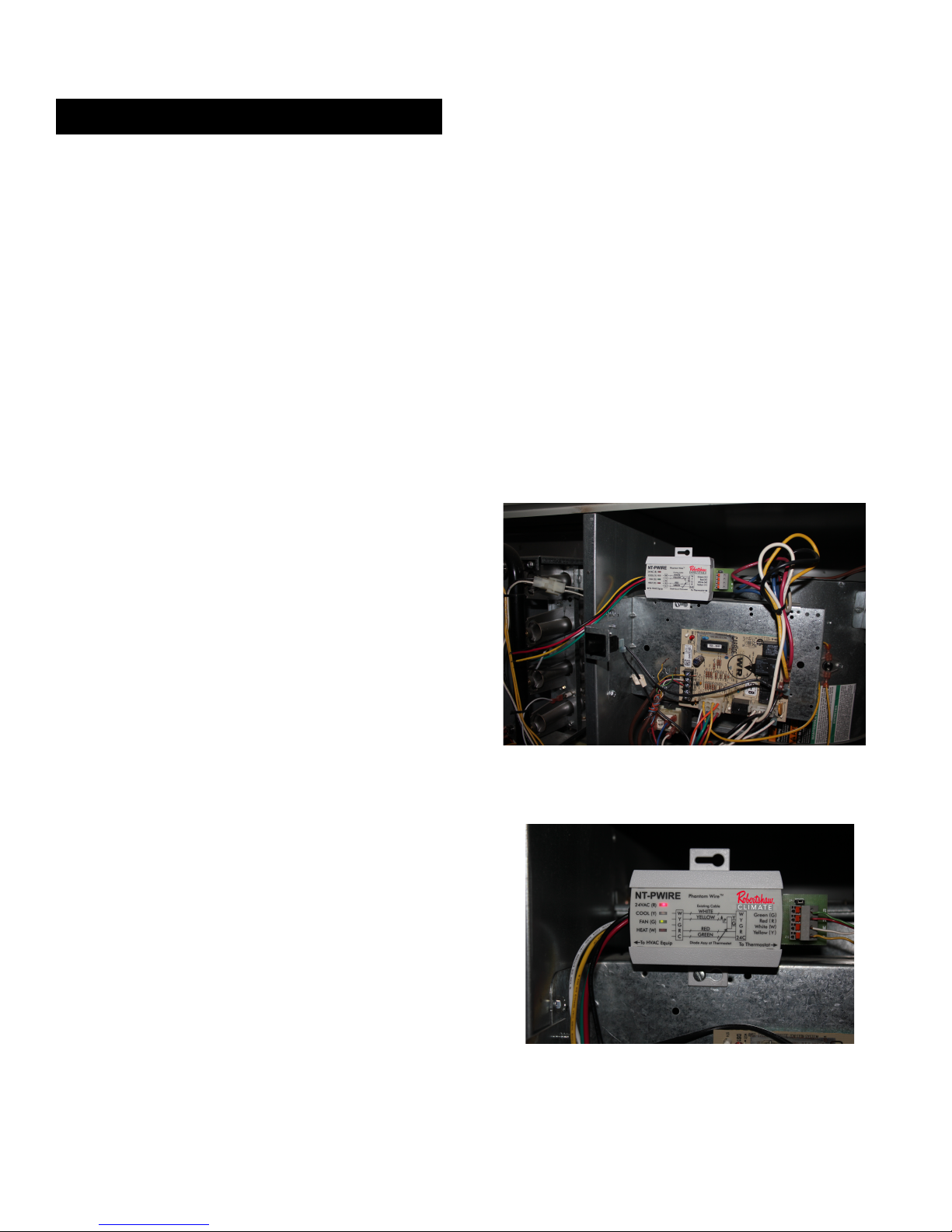
8) Mount RS-PWIRE device in a location inside
the equipment board area. Make sure it is
not in the way of any moving parts. Device
must be mounted close enough to the
thermostat wiring board for connection.
9) Install thermostat cable to the RS-PWIRE screwless terminals
a. Green wire to G terminal
b. Red wire to R terminal
c. White wire to W terminal
d. Yellow wire to Y terminal
Page 3

© 2017 Robertshaw Climate 844-362-4822 Page 3 250037-01
10) Install RS-PWIRE cable to corresponding
terminals on HVAC thermostat wiring board
a. Green wire to G terminal
b. Red wire to R terminal
c. White wire to W terminal
d. Yellow wire to Y terminal
e. Black wire to C terminal
11) If the HVAC system is a Heat Pump, install the Reversing Valve (O or B) and any other
necessary connections per HVAC system requirements.
12) If the HVAC system is a 2-stage unit, install any other necessary connections per HVAC
system requirements.
FINAL CHECKOUT
13) Turn on HVAC equipment power.
Red (24VAC - R) LED will be on.
If not, check your connections.
14) FAN TEST - At thermostat, manually turn on Fan. Check LEDs on RS-PWIRE.
GAS / ELECTRIC HVAC SYSTEM
HEAT PUMP HVAC SYSTEM
Red (24VAC - R) LED will be on.
Red (24VAC - R) LED will be on.
Green (FAN - G) LED will be on.
Green (FAN - G) LED will be on.
If not, check your connections.
(Remember to turn the Fan back to ‘Auto’ when test is completed).
15) COOL TEST - At thermostat, turn on Cooling. Check LEDs on RS-PWIRE.
GAS / ELECTRIC HVAC SYSTEM
HEAT PUMP HVAC SYSTEM
Red (24VAC - R) LED will be on.
Red (24VAC - R) LED will be on.
Blue (COOL - Y) LED will be on.
Blue (COOL - Y) LED will be on.
Green (FAN - G) LED will be on.
Green (FAN - G) LED will be on.
If not, check your connections.
Page 4

© 2017 Robertshaw Climate 844-362-4822 Page 4 250037-01
16) HEAT TEST - At thermostat, turn on Heating. Check LEDs on RS-PWIRE.
GAS / ELECTRIC HVAC SYSTEM
HEAT PUMP HVAC SYSTEM
Red (24VAC - R) LED will be on.
Red (24VAC - R) LED will be on.
Green (FAN - G) LED may or may not be
on, depending on gas or electric heat.
Blue (COOL - Y) LED will be on.
(THIS IS COMPRESSOR-HEAT)
Red (HEAT - W) LED will be on.
Green (FAN - G) LED will be on.
If not, check your connections.
17) AUX HEAT TEST (HEAT PUMP ONLY) –
At thermostat, turn on Heating. Then Turn on Aux Heat. Check LEDs on RS-PWIRE.
GAS / ELECTRIC HVAC SYSTEM
HEAT PUMP HVAC SYSTEM
N/A
Red (24VAC - R) LED will be on.
N/A
Blue (COOL - Y) LED will be on.
(THIS IS COMPRESSOR-HEAT)
N/A
Green (FAN - G) LED will be on.
N/A
Red (HEAT - W) LED will be on.
If not, check your connections.
SPECIFICATIONS
DEVICE ASSEMBLY at HVAC EQUIPMENT
Rated Voltage: 20V to 30VAC, 24VAC nominal
Rated Output Current: 5A / 250VAC, 5A / 28VDC
Thermostat Terminations: All Screwless, G – Green, R – Red, W – White, Y – Yellow
Equipment Wires: 9” with Stripped & Tinned Ends
R – Red (24VAC+), C – Black (24VAC Common)
W – White (Heat), Y – Yellow (Cool), G – Green (Fan)
Jumpers: JP1 – Remove Jumper to Disable LEDs
DIODE ASSEMBLY at THERMOSTAT
Diode Assembly Terminations:
Y – Yellow (Cool), G – Green (Fan), B – Blue (Connect to Thermostat YELLOW wire)
Thermostat Terminations:
R – Red (24VAC+), C – 24VAC Common (Green), W – Heat (White),
Y - Connect to Diode Assembly BLUE wire
 Loading...