

Page 1

The Twin Fire
Unitary Infrared Heater
Submittal: TF-Series
Job:
Location:
Engineer:
Gas Specs:
Date:
QTY. MODEL NO. TF UNIT INPUT BTU/HR
QTY. MODEL NO. TF UNIT INPUT BTU/HR
QTY. MODEL NO. TF UNIT INPUT BTU/HR
QTY. MODEL NO. TF UNIT INPUT BTU/HR
TOTAL INPUT BTU/HR
Important
Before installation and operation of heating equipment, read and understand the
Installation, Operation and Service Manual.
ROBERTS GORDON® products are to be installed only in accordance with local laws, codes and regulations, and only by a contractor qualified in
the installation and service of gas-fired heating equipment.
1250 William Street 241 South Service Road West
P.O. Box 44 Grimsby, Ontario L3M 1Y7
Buffalo, New York 14240-0044 Canada
Telephone: 716.852.4400 Telephone: 905.945.5403
Fax: 716.852.0854 Fax: 905.945.0511
Toll Free: 800.828.7450
www.rg-inc.com
Applications, engineering and detailed guidance on systems design, installation and product performance is available upon request.
Roberts-Gordon Roberts-Gordon Canada Inc.
© Copyright 2001 Roberts-Gordon
P/N190600NA 06/01
Page 2

Page 3

TABLE OF CONTENTS
STANDAR D PARTS LIST............................................. 1
Contents of TF-Series Burner Carton ..................... 1
Contents of Core and Extension Packages............. 1
GENERAL SPECIFICATIONS ...................................... 2
Material Specification .............................................. 2
Reflectors ................................................................ 2
Heater Specifications............................................... 2
Ignition .....................................................................2
Suspension Specifications....................................... 2
Controls Specifications............................................ 2
Gas Pressure at Manifold:.......................................2
Dimensions:............................................................. 2
Pipe Connection:..................................................... 2
Gas Inlet Pressure:.................................................. 2
Electrical Rating (all Models): .................................. 2
Standard Reflector.................................................. 3
One Side Reflector .................................................. 3
Two Side Reflectors ................................................ 3
45° Tilt Reflector ...................................................... 4
U-Tube, Standard Reflector..................................... 4
U-Tube, Full 45° ...................................................... 4
U-Tube, Opposite 45° Reflector .............................. 5
2-Foot Deco Grille, 1-Foot Deco Grille and
Protective Grille....................................................... 5
Lower Clearance Shield*.........................................5
Venting .................................................................... 6
TF-SERIES ASSEMBLY OVERVIEW........................... 7
Major Component Descriptions ............................... 7
TF-Series Linear Assembly Overview ................... 8
HEATER INSTALLATION............................................. 9
Critical Hanger Placement....................................... 9
TF-Series Linear Layout Overview ......................... 10
TF-Series Linear Layout Overview
(Continued).............................................................. 11
BBurner Tube Installation........................................ 12
Burner Installation.................................................... 12
Tube Clamp Package Installation............................ 13
Coupling and Tube Assembly.................................. 13
Coupling and Tube Assembly (Continued).............. 14
Turbulator Installation .............................................. 15
Reflector Installation................................................ 15
Reflector, U-Clip and Reflector Support
Installation ............................................................... 16
OPTIONAL HEATER ACCESSORIES.......................... 17
TF-Series U-Tube Assembly Overview .................. 17
TF-Series U-Tube Layout Overviews ..................... 18
TF-Series U-Tube Layout Overviews
(Continued).............................................................. 19
ELBOW PACKAGE CONFIGURAT ION........................20
Elbow Installation.....................................................20
Elbow Installation (continued) ..................................20
Reflector Joint Installation........................................20
Reflector Joint Detail................................................21
REFLECTOR SIDE EXTENSION..................................22
Bracket Installation...................................................22
Side Reflector Installation........................................22
LOWER CLEARANCE SHIELD INSTALLATION.........23
Shield Support Strap Assembly...............................23
TWO-FOOT DECORATIVE GRILLE INSTALLATION..23
Grille Installation......................................................23
Frame Shield Installation .........................................24
Reflector Side Extension Installation ......................24
ONE-FOOT DECORATIVE GRILLE INSTALLATION..25
One-Foot Decorative Grille Bracket.........................25
Decorative Grille......................................................25
Joint Piece and Reinforcement................................25
End Piece and Reflector End Cap...........................26
90° Elbow.................................................................26
PROTECTIVE GRILLE INSTALLATION.......................27
Silicone Cap Installation...........................................27
Grille End Cap Installation .......................................27
Grille Installation......................................................27
VENTING........................................................................28
Horizontal Ventilation 4" (10 cm) Pipe .....................28
Vertical Ventilation 4" (10 cm) Pipe..........................28
CFlexible Boot Installation (Single Vent)..................29
Common Sidewall Venting.......................................29
Vertical Ventilation 6" (15 cm) Pipe .........................30
Flexible Boot Installation (Common Vent)................30
OUTSIDE COMBUSTION AIR SUPPLY.......................31
Vertical Outside Air Supply .....................................31
Horizontal Outside Air Supplly.................................31
GAS PIPING...................................................................32
WIRING..........................................................................33
Line Voltage Thermostat Wiring...............................33
Low Voltage Thermostat and Relay Wiring..............34
Electrical Connection to the Burner .........................36
INTERNAL BURNER DIAGRAM...................................37
THE ROBERTS GORDON® VANTAGE® TF LIMITED
WARRANTY...................................................................38
© 2004
All rights reserved. No part of this work covered by the copyrights herein may be reproduced
or copied in any form or by any means - graphic, electronic, or mechanical, including
photocopying, recording, taping or information storage and retrieval systems - without the
written permission of Roberts-Gordon.
Printe d in U.S.A.
Page 4

Page 5

ROBERTS GORDON® TF-SERIES SUBMITTAL SHEET
STANDARD PARTS LIST
Contents of TF-Series Burner Carton
Part No. Descrip tion TF-120 TF-160 TF-200 TF-250 TF-300 TF-350 TF-380
090XXXXX TF Burner Assembly (Rate and Fuel Varies) 1 1 1 1 1 1 1
02568200 Gasket 1 1 1 1 1 1 1
190100NA Installation, Operation and Service Manu al 1 1 1 1 1 1 1
94273914 Hex Head Bolts 5/ 16-18 Rolok 8 8 8 8 8 8 8
96411600 Split Lock washer 8 8 8 8 8 8 8
91412203 Flexible Gas Connector Assembly - 3/ 4" NPT 1 1 1 1 1 1 1
03051503 Turbulator Adapter 2 2 2 - - - 03051504
Turbulator 2.5
'
(76 cm) Aluminized Steel
884----
91412800 Flexible Boot 2 2 2 2 2 2 2
91901300 Boot Clamp 4 4 4 4 4 4 4
09080000 Vent Sleeve 2 2 2 2 2 2 2
Contents of Core and Extension Packages
Core Packages Extension Packages
Hot Rolled
with
Aluminum
Reflector
Alu minized
with
Aluminum
Refl ector
Aluminized
with
Stainless
Steel
Hot Rolled
with
Aluminum
Reflector
Aluminized with
Aluminum
Reflector
Aluminized with
Sta inless Steel
Refle ctor
Reflector
Part No. Description
91409300
91409408
03051101
Tube, Hot Rolled Steel, 10
'
(3m)
Tube, HT Aluminized, 10' (3 m)
Burner Tube, ALUMI-THERM® Steel, 10' (3m)
20
'
30
'
40
'
20
'
30
'
40
'
20
'
30
'
40
'
10
'
20
'
30
'
40
'
10
'
20
'
30
'
40
'
10
'
20
'
30
'
(6m)
(9m )
(12m)
(6 m )
(9m)
(12m)
(6m)
(9 m )
(12m)
(3m)
(6 m )
(9m)
(12m
(3m)
(6 m )
(9m)
(12m
(3m)
(6 m )
(9m)
40
(12m
123------1234--------
- - -123123--- -12341234
111111111------------
'
01312700 Coupling Assembly 1 23123123123412341234
02750303
Standard Reflector, 8
'
(3.5m)
346346-- -23462346- -- -
02750800 End Cap 2 22222--------------027503SS Stainless Steel Reflector, 8’ (3.5m) ------346--------2346
027508SS Stainless Steel End Cap ------222-----------03090100 Tube and Reflector Hanger 3 45345345123412341234
91907302 S-Hook 6 8 10 6 8 10 6 8 10 2 4 6 824682468
03050010 Reflector Support Package
235235457234623462346
(Strap, Wire Form, Screws)
91107720 U-Clip Package 1 11111111111111111111
90502700 Vent Adapter (Not required for TF Models) 1 11111111-----------01318901 Tube Clamp Package 1 11111222------------
Part Number
CP20HRS
CP30HRS
© 2004 Roberts-Gordon
CP40HRS
CP20ALUM
CP30ALUM
CP40ALUM
CP 20 AL U MSS
APPLICATION S, ENGI NEERING AND DETAILE D GUIDANCE ON S YSTEMS DES IGN, INSTALLATION AND P RODUCT PE RFORMANC E IS AVAILABLE UP ON REQUEST. ROB ERTS GORDON® PRODUCT S ARE T O BE
INSTALLED ONL Y IN ACCORDA NCE WI TH LOC AL LAWS , CODES AND REGUL AT IONS, AND ONLY BY A C ONTRACTOR QUA LIFIED I N THE I NSTALLATION AND SERV ICE OF GAS- FIRED HEATING EQUIPMENT.
CP 30 AL U MSS
CP 40 AL U MSS
EXP10HRS
EXP20HRS
EXP30HRS
EXP40HRS
EXP10ALUM
EXP20ALUM
EXP30ALUM
EXP40ALUM
EXP10ALUMSS
EXP20ALUMSS
EXP30ALUMSS
EXP40ALUMSS
Page 6

ROBERTS GORDON® TF-SERIES SUBMITTAL SHEET
GENERAL SPECIFICATIONS
Material Specification
Reflectors
.024 Aluminum
Heater Specifications
Ignition
Automatic direct spark ignition with safety shut-off.
Suspension Specifications
Hang heater with materials with a minimum working
load of 75 lbs (33 kg).
Controls Specifications
Time switches, thermostats, etc. can be wired into
the electrical supply. External controls supplied as an
optional extra.
General Specifications for TF-Series heaters are as follows:
Side View
Reflector
23.5"
(60 cm)
End View
13.75"
(35 cm)
Length "A"
9.5"
(24 cm)
Length "A"
Length “A” Each Side Recommended
Heat Input
Rate
Minimum Maximum
Minimum Mounting
Height*
Model (BTUH X1000) Linear U-Tube Linear U-Tube Space Spot
TF-120 120 20' (6 m) 11'6" (4 m) 20' (6 m) 11'6" (4 m) 12' (4 m) 9' (3 m)
TF-160 160 20' (6 m) 11'6" (4 m) 30' (9 m) 16'6" (5 m) 15' (5 m) 11' (3 m)
TF-200 200 30' (9 m) 16'6" (5 m) 40' (12 m) 21'6" (7 m) 15' (5 m) 12' (4 m)
TF-250 250 40' (12 m) 21’ 6" (7 m) 50' (15 m) 26'6" (8 m) 20' (6 m) 15' (5 m)
TF-300 300 50' (15 m) 26'6" (8 m) 60' (18 m) 31'6" (10 m) 20' (6 m) 20' (6 m)
TF-350 350 50' (15 m) 26'6" (8 m) 70' (21 m) 36'6" (11 m) 25' (8 m) 23' (7 m)
TF-380 380 60' (18 m) 31'6" (10 m) 80' (24 m) 41'6" (13 m) 25' (8 m) 23' (7 m)
Gas Pressure at Manifold:
Natural Gas: 3.5" w.c.
LP Gas: 10.5" w.c.
Dimensions:
Vent Connection Size:
4" (10 cm) or 6" (15 cm)
Outside Air Connection Size:
4" (10 cm) or 6" (15 cm)
Refer to figure above for dimensional information.
© 2004 Roberts-Gordon
APPLI CATIONS, ENGINEERING AND DE TAILE D GUIDANCE ON S YSTEMS DE SIGN, INS TALLA TION A ND PRODUCT PE RFORMANCE IS AVAILABLE UPO N REQUEST. ROBERTS GO RDON® PRODUCTS ARE TO BE
INSTALLED ONLY I N ACCOR DANC E WITH L OCAL L AW S, C ODES AND RE GULATIONS, AND ONLY BY A CONTRACTO R QUALIFIED IN THE INST ALLAT ION AND SERVICE OF GAS-F IRED HEATING EQUIPMEN T.
Pipe Connection:
3/4" NPT
Gas Inlet Pressure:
Natural Gas: 5.0" w.c. Minimum
16.0" w.c. Maximum
LP Gas: 12.0" w.c. Minimum
16.0" w.c. Maximum
Electrical Rating (all Models):
120V - 60 Hz., 1.0 Amp
Page 7

ROBERTS GORDON® TF-SERIES SUBMITTAL SHEET
NOTE: 1. All dimensions are from the surfaces of all tubes, couplings and elbows.
2. Clearances B, C and D can be reduced by 50% after 25' (7.5 m) of tubing downstream
from where the burner and burner tube connect.
Standard Reflector
(inches) (centimeters)
Model ABCDABCD
A
B
C
D
One Side Refle ctor
A
B
C
D
TF-120 6 35 63 35 16 89 161 89
TF-160 6 38 66 38 16 97 168 97
TF-200 6 40 71 40 16 102 181 102
TF-250 6 46 77 46 16 117 196 117
TF-300 6 50 80 50 16 127 204 127
TF-350 8 52 82 52 21 133 209 133
TF-380 8 52 82 52 21 133 209 133
(inches) (centimeters)
Model ABCDABCD
TF-120 6 9 63 47 16 23 161 120
TF-160 6 9 70 54 16 23 178 138
TF-200 6 9 77 59 16 23 196 150
TF-250 6 9 83 65 16 23 211 166
TF-300 6 9 86 69 16 23 219 176
TF-350 8 9 88 73 21 23 224 186
TF-380 8 9 88 73 21 23 224 186
Two Si de Reflectors
A
B
C
D
© 2004 Roberts-Gordon
(inches) (centimeters)
Model ABCDABCD
TF-120 6 23 66 23 16 59 168 59
TF-160 6 25 72 25 16 64 183 64
TF-200 6 27 78 27 16 69 199 69
TF-250 6 32 84 32 16 82 214 82
TF-300 6 35 88 35 16 89 224 89
TF-350 8 40 91 40 21 102 232 102
TF-380 8 40 91 40 21 102 232 102
APPLICATION S, ENGI NEERING AND DETAILE D GUIDANCE ON S YSTEMS DES IGN, INSTALLATION AND P RODUCT PE RFORMANC E IS AVAILABLE UP ON REQUEST. ROB ERTS GORDON® PRODUCT S ARE T O BE
INSTALLED ONL Y IN ACCORDA NCE WI TH LOC AL LAWS , CODES AND REGUL AT IONS, AND ONLY BY A C ONTRACTOR QUA LIFIED I N THE I NSTALLATION AND SERV ICE OF GAS- FIRED HEATING EQUIPMENT.
Page 8

ROBERTS GORDON® TF-SERIES SUBMITTAL SHEET
NOTE: 1. All dimensions are from the surfaces of all tubes, couplings and elbows.
2. Clearances B, C and D can be reduced by 50% after 25' (7.5 m) of tubing downstream
from where the burner and burner tube connect.
45
° Tilt Reflector
(inches) (centimeters)
Model ABCDABCD
A
C
B
D
U-Tube, Standard Reflector
A
C
DB
TF-120 8 8 60 54 21 21 153 138
TF-160 8 8 66 60 21 21 168 153
TF-200 10 8 74 64 26 21 188 163
TF-250 10 8 78 69 26 21 199 176
TF-300 12 8 84 74 31 21 214 188
TF-350 12 8 85 79 31 21 216 201
TF-380 12 8 85 79 31 21 216 201
(inches) (centimeters)
Model ABCDABCD
TF-120 6 35 63 30 16 89 161 77
TF-160 6 38 69 37 16 97 176 94
TF-200 6 40 76 39 16 102 194 100
TF-250 6 46 79 43 16 117 201 110
TF-300 6 50 84 47 16 127 214 120
TF-350 8 54 87 51 21 138 221 130
TF-380 8 54 87 51 21 138 221 130
U-Tube, Full 45°
A
B
D
C
© 2004 Roberts-Gordon
(inches) (centimeters)
Model ABCDABCD
TF-120 8 8 60 42 21 21 153 107
TF-160 8 8 66 46 21 21 168 117
TF-200 8 8 74 52 21 21 188 133
TF-250 8 8 78 61 21 21 199 155
TF-300 8 8 84 66 21 21 214 168
TF-350 8 8 85 70 21 21 216 178
TF-380 8 8 85 70 21 21 216 178
APPLI CATIONS, ENGINEERING AND DE TAILE D GUIDANCE ON S YSTEMS DE SIGN, INS TALLA TION A ND PRODUCT PE RFORMANCE IS AVAILABLE UPO N REQUEST. ROBERTS GO RDON® PRODUCTS ARE TO BE
INSTALLED ONLY I N ACCOR DANC E WITH L OCAL L AW S, C ODES AND RE GULATIONS, AND ONLY BY A CONTRACTO R QUALIFIED IN THE INST ALLAT ION AND SERVICE OF GAS-F IRED HEATING EQUIPMEN T.
Page 9

ROBERTS GORDON® TF-SERIES SUBMITTAL SHEET
NOTE: 1. All dimensions are from the surfaces of all tubes, couplings and elbows.
2. Clearances B, C and D can be reduced by 50% after 25' (7.5 m) of tubing downstream
from where the burner and burner tube connect.
U-Tube, Opposite 45
° Reflector
(inches) (centimeters)
Model ABCDABCD
A
B
C
D
TF-120 8 54 60 22 21 138 153 56
TF-160 8 60 66 22 21 153 168 56
TF-200 10 64 74 22 26 163 188 56
TF-250 10 70 78 22 26 178 199 56
TF-300 12 74 84 22 31 188 214 56
TF-350 12 76 85 22 31 194 216 56
TF-380 12 76 85 22 31 194 216 56
2-Foot Deco Grille, 1-Foot Deco Grille and Protective Grille
(inches) (centimeters)
Model ABCDABCD
A
C
B
D
TF-120 6 35 63 35 16 89 161 89
TF-160 6 38 66 38 16 97 168 97
TF-200 6 40 71 40 16 102 181 102
TF-250 6 46 77 46 16 117 196 117
TF-300 6 50 80 50 16 127 204 127
TF-350 8 52 82 52 21 133 209 133
TF-380 8 52 82 52 21 133 209 133
Lower Clearance Shield*
(inches) (centimeters)
Model ABCDABCD
TF-120 6 39 33 39 16 100 84 100
A
TF-160 6 40 38 40 16 102 97 102
TF-200 6 50 44 50 16 127 112 127
TF-250 6 54 48 54 16 138 122 138
B
C
D
TF-300 6 55 50 55 16 140 127 140
TF-350** Unapproved
Unapproved
TF-380** Unapproved Unapproved
*When installed in the first 20’ (6 m) on each side of the burner.
**Roberts-Gordon prohibits the installation of this heater for all unapproved applications.
© 2004 Roberts-Gordon
APPLICATION S, ENGI NEERING AND DETAILE D GUIDANCE ON S YSTEMS DES IGN, INSTALLATION AND P RODUCT PE RFORMANC E IS AVAILABLE UP ON REQUEST. ROB ERTS GORDON® PRODUCT S ARE T O BE
INSTALLED ONL Y IN ACCORDA NCE WI TH LOC AL LAWS , CODES AND REGUL AT IONS, AND ONLY BY A C ONTRACTOR QUA LIFIED I N THE I NSTALLATION AND SERV ICE OF GAS- FIRED HEATING EQUIPMENT.
Page 10

ROBERTS GORDON® TF-SERIES SUBMITTAL SHEET
NOTE: 1. All dimensions are from the surfaces of all tubes, couplings and elbows.
2. Clearances B, C and D can be reduced by 50% after 25' (7.5 m) of tubing downstream
from where the burner and burner tube connect.
Venting
A
E
Unvented
Infrared Tubes
Vented
Vent
Pipes
F
(inches) (centimeters)
Model A E F A E F
TF-120 14 18 18 36 46 46
TF-160 20 24 18 51 61 46
TF-200 20 24 18 51 61 46
TF-250 20 24 18 51 61 46
TF-300 20 30 18 51 77 46
TF-350 20 30 18 51 77 46
TF-380 20 30 18 51 77 46
© 2004 Roberts-Gordon
APPLI CATIONS, ENGINEERING AND DE TAILE D GUIDANCE ON S YSTEMS DE SIGN, INS TALLA TION A ND PRODUCT PE RFORMANCE IS AVAILABLE UPO N REQUEST. ROBERTS GO RDON® PRODUCTS ARE TO BE
INSTALLED ONLY I N ACCOR DANC E WITH L OCAL L AW S, C ODES AND RE GULATIONS, AND ONLY BY A CONTRACTO R QUALIFIED IN THE INST ALLAT ION AND SERVICE OF GAS-F IRED HEATING EQUIPMEN T.
Page 11

ROBERTS GORDON® TF-SERIES SUBMITTAL SHEET
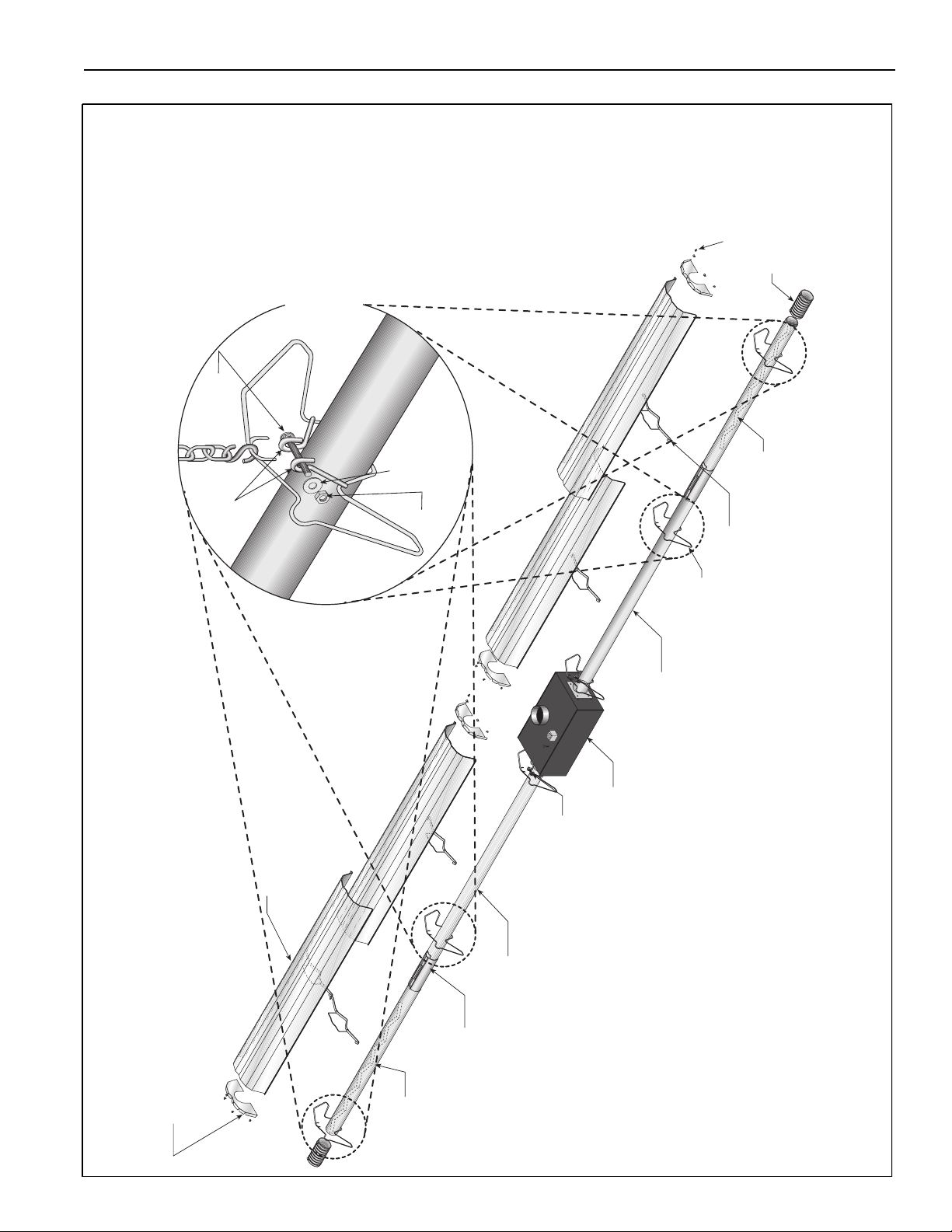
TF-SERIES ASSEMBLY OVERVIEW
Major Component Descriptions
Burner with Tube Gasket
Must be installed with the
flame observation
window facing down.
Burner Tube
Supplied in 10
'
(3 m) lengths. Burner
tube is always the first tube
after the burner.
Refle ctor E nd Cap
Punch out center
section to
accommodate heat
exchanger tube.
Reflector
(Aluminum or
Stainless
Steel)
Alternate overlap as
shown on overview and
on Page 10, Figure .
Minimum overlap is 7” (18 cm).
Tube
Hot Rolled or Heat
Treated Aluminized Tube
Supplied in 10’ (3 m) lengths.
Coupling Assembly
with Lock
Tube and Reflector Hanger
with Clamp Package
Position this hanger no more
than 4” (10 cm) away from
the burner.
Tube and Reflector Hanger
Suspend system from these
hangers.
Reflector Support Strap &
Wire Form
Flex Gas Line with
Shut Off Cock
Flexible Boot
Flexible boot is used to
connect the last tube to
the vent.
Vent Sleeve
Vent Sleeve installed
inside flexible boot.
Turbulator
Turbulator must be
installed in the last standard
section of tube. Turbulator is
not required on the TF-250/
300/350/380. For installation
see Page 15, Section .
© 2004 Roberts-Gordon
APPLICATION S, ENGI NEERING AND DETAILE D GUIDANCE ON S YSTEMS DES IGN, INSTALLATION AND P RODUCT PE RFORMANC E IS AVAILABLE UP ON REQUEST. ROB ERTS GORDON® PRODUCT S ARE T O BE
INSTALLED ONL Y IN ACCORDA NCE WI TH LOC AL LAWS , CODES AND REGUL AT IONS, AND ONLY BY A C ONTRACTOR QUA LIFIED I N THE I NSTALLATION AND SERV ICE OF GAS- FIRED HEATING EQUIPMENT.
Page 12
ROBERTS GORDON® TF-SERIES SUBMITTAL SHEET
F
la
t
W
a
s
h
e
r
Nut
(Tor
que
120 in/lb
13.56
Nm
)
Tube
Clamp
B
o
lt
TF-Series Linear Assembly Overview
on each side of the burner.
used at the two farthest hangers
For shorter than minimum
suspension lengths,
tube clamps must be
U-Clips
Flexible Boot
Reflector
Turbulator
Reflector Support
Burner Tube
Tube and Reflector Hanger
Burner
Tube Clamp Package
Reflector End Cap
© 2004 Roberts-Gordon
APPLI CATIONS, ENGINEERING AND DE TAILE D GUIDANCE ON S YSTEMS DE SIGN, INS TALLA TION A ND PRODUCT PE RFORMANCE IS AVAILABLE UPO N REQUEST. ROBERTS GO RDON® PRODUCTS ARE TO BE
INSTALLED ONLY I N ACCOR DANC E WITH L OCAL L AW S, C ODES AND RE GULATIONS, AND ONLY BY A CONTRACTO R QUALIFIED IN THE INST ALLAT ION AND SERVICE OF GAS-F IRED HEATING EQUIPMEN T.
Tube
Burner Tube
Coupling
Page 13
ROBERTS GORDON® TF-SERIES SUBMITTAL SHEET
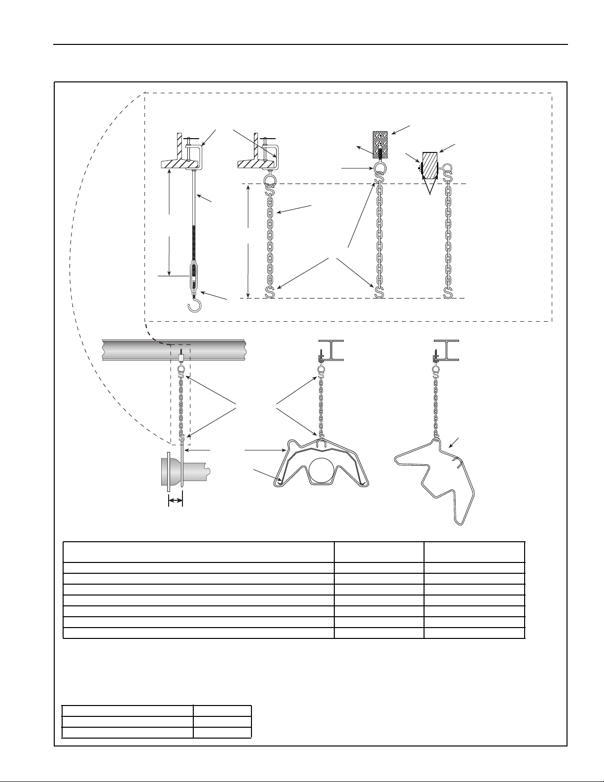
HEATER INSTALLATION
Critical Hanger Placement
Typical Suspension Details
24" min.*
(61 cm)
Beam Clamp
Rod (3/8")
X*
Turnbuckle
Not Included
S Hooks
Concrete Beam
Anchor
Locknut
Screw Hook
(3/8")
Chain size
3/16" minimum
Washers
S Hooks
* Allows for thermal expansion of system
Wood Beam
Side View
Hanger
Hanger
Reflector
Must Be Within 4" (10 cm) Front View
Total Straight Length (both sides) or Length from U-Tube to U-Tube
in a Double "U" Layout
0’ - 50’ ±1” (3 cm) 12” (31 cm)
51’ - 60’ ±2” (5 cm) 18” (46 cm)
61’ - 80’ ±3” (8 cm) 24” (61 cm)
81’ - 100’ ±4” (10 cm) 30" (76 cm)
101’ - 120’ ±5” (13 cm) 36" (91 cm)
121’ - 140’ ±6” (15 cm) 42" (107 cm)
141’ - 160’ ±7” (18 cm) 48" (122 cm)
Typical Expansion
Each Si de
45° Angle
Minimum “X” Length
If the installation requires a shorter suspension length than the minimum listed, the suspension
length may be reduced by 6" (16 cm). In this case tube clamps MUST be used at the two farthest
hangers on each side of the burner. See Page 8, Figure .
Description Part Number
S-Hoo k 9190 7302
Tube/Refl ecto r Hanger 0309 01 00
© 2004 Roberts-Gordon
APPLICATION S, ENGI NEERING AND DETAILE D GUIDANCE ON S YSTEMS DES IGN, INSTALLATION AND P RODUCT PE RFORMANC E IS AVAILABLE UP ON REQUEST. ROB ERTS GORDON® PRODUCT S ARE T O BE
INSTALLED ONL Y IN ACCORDA NCE WI TH LOC AL LAWS , CODES AND REGUL AT IONS, AND ONLY BY A C ONTRACTOR QUA LIFIED I N THE I NSTALLATION AND SERV ICE OF GAS- FIRED HEATING EQUIPMENT.
Page 14
ROBERTS GORDON® TF-SERIES SUBMITTAL SHEET
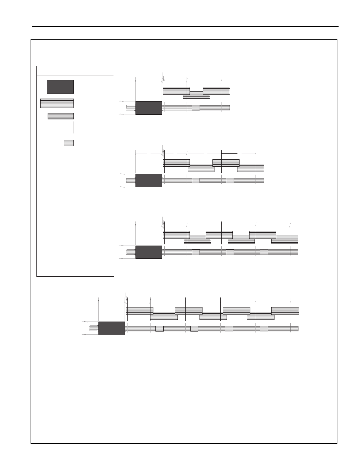
TF-Series Linear Layout Overview
Linear layouts showing one side. Use same measurements for the other side.
LEGEND
Burner
Reflector
Tube
Tube/Reflector
Hanger
Coupling
Assembly
a = 14" (36 cm)
reflector width (not shown)
b = 2" (5 cm)
end cap to burner
c = 2" (5 cm)
end cap to hanger
d = 7'6" (229 cm)
distance first hanger
e = 10' (305 cm)
distance between hangers
f = 9.5" (24 cm)
burner height
b
c
g
f
TF-120
de
20' (6m) Tube Length (each side)
TF-160
b
c
g
f
TF-160
de
30' (9m) Tube Length (each side)
e
TF-200
b
c
g
de
e e
g = 23.5" (60 cm)
burner length
f
TF-200
40' (12m) Tube Length (each side)
TF-250
b
c
g
f
de
TF-250
50' (15m) Tube Length (each side)
e e e
TF-300
TF-350
© 2004 Roberts-Gordon
APPLI CATIONS, ENGINEERING AND DE TAILE D GUIDANCE ON S YSTEMS DE SIGN, INS TALLA TION A ND PRODUCT PE RFORMANCE IS AVAILABLE UPO N REQUEST. ROBERTS GO RDON® PRODUCTS ARE TO BE
INSTALLED ONLY I N ACCOR DANC E WITH L OCAL L AW S, C ODES AND RE GULATIONS, AND ONLY BY A CONTRACTO R QUALIFIED IN THE INST ALLAT ION AND SERVICE OF GAS-F IRED HEATING EQUIPMEN T.
Page 15

ROBERTS GORDON® TF-SERIES SUBMITTAL SHEET
TF-Series Linear Layout Overview (Continued)
b
c
g
f
de
e e e e
TF-300
60' (18m) Tube Length (each side)
TF-350
TF-380
b
c
g
de
e e e e e
b
f
TF-350
70' (21m) Tube Length (each side)
TF-380
b
c
g
de
b
e e e e e
f
TF-380
© 2004 Roberts-Gordon
80' (24m) Tube Length (each side)
APPLICATION S, ENGI NEERING AND DETAILE D GUIDANCE ON S YSTEMS DES IGN, INSTALLATION AND P RODUCT PE RFORMANC E IS AVAILABLE UP ON REQUEST. ROB ERTS GORDON® PRODUCT S ARE T O BE
INSTALLED ONL Y IN ACCORDA NCE WI TH LOC AL LAWS , CODES AND REGUL AT IONS, AND ONLY BY A C ONTRACTOR QUA LIFIED I N THE I NSTALLATION AND SERV ICE OF GAS- FIRED HEATING EQUIPMENT.
Page 16

ROBERTS GORDON® TF-SERIES SUBMITTAL SHEET
7' 6" ± 1'
(229 cm ± 25 cm)
S
Hook
Burner Tube
Hanger
29"± 2"
(73 cm ± 5 cm)
BBurner Tube Installation
NOTE:
Tubing requires a downward
slope of 1/2" (13 mm)
per 20' (6 m) away
from burner.
Description Par t Numbe r
Burn er Tu be 03051 XXX
S-Hook 9190 7302
Tube/Ref le cto r Ha nger 0309 0100
Offset mounting
hole must be
to the top
Weld Seam
must be to the
bottom of the tube.
Burner Installation
Description Part Number
Bolt 9427 3914
Lock Wash er 96 41160 0
Gasket 02568200
Burn er 090XX XXX
© 2004 Roberts-Gordon
APPLI CATIONS, ENGINEERING AND DE TAILE D GUIDANCE ON S YSTEMS DE SIGN, INS TALLA TION A ND PRODUCT PE RFORMANCE IS AVAILABLE UPO N REQUEST. ROBERTS GO RDON® PRODUCTS ARE TO BE
INSTALLED ONLY I N ACCOR DANC E WITH L OCAL L AW S, C ODES AND RE GULATIONS, AND ONLY BY A CONTRACTO R QUALIFIED IN THE INST ALLAT ION AND SERVICE OF GAS-F IRED HEATING EQUIPMEN T.
Bolt
Lock Washer
Gasket
Burner
Page 17

ROBERTS GORDON® TF-SERIES SUBMITTAL SHEET
Bolt
Flat
Washer
Tube Clamp
Tube Clamp Package Installation
Nut
(Tor
que
120 in/lb
13.56 Nm
)
Description Part Number
Tube Clamp Package 01318901
Tube Clamp 01396801
Bolt 97113940
Flat Washer 95211600
Nut 921 13900
Coupling a nd Tube Asse mbly
Close coupling
A
with tab
Open
Closed
Insert tubes into coupling
C
Tab
Start Slide bar/Coupling Lock
B
onto coup ling
3" (8 cm) to
4" (10 cm)
Tighte n coupling to join tube s
D
Slide Bar/Coupling Lock
Wide end
Coupling
© 2004 Roberts-Gordon
Slide Bar/Coupling Lock
Orient coupling so that
the impact block is in the
2:00 or 10:00 oclock
positions
Tube
Tube
APPLICATION S, ENGI NEERING AND DETAILE D GUIDANCE ON S YSTEMS DES IGN, INSTALLATION AND P RODUCT PE RFORMANC E IS AVAILABLE UP ON REQUEST. ROB ERTS GORDON® PRODUCT S ARE T O BE
INSTALLED ONL Y IN ACCORDA NCE WI TH LOC AL LAWS , CODES AND REGUL AT IONS, AND ONLY BY A C ONTRACTOR QUA LIFIED I N THE I NSTALLATION AND SERV ICE OF GAS- FIRED HEATING EQUIPMENT.
Descr ipti on Part Number
Coupling 013 29600
Slide bar/Coupling Lock 01329700
Tube 91 409X XX
Tube
Coupling
Page 18

ROBERTS GORDON® TF-SERIES SUBMITTAL SHEET
Coupling and Tube Assembly (Continued)
Tighten slide bar as shown below
Drive Slide Bar until tight.
End of Slide Bar should be
within tolerance listed below.
± 2" (5 cm)
Correct Slide Bar
dimensions
Incorrect Slide Bar
position
• Repeat A - D until all tubes are assembled.
Coupling and Tube Assembly (Continued)
Tube Length Per Side
Model
TF-120 20’ (6 m) 20’ (6 m)
TF-160 20’ (6 m) 30’ (9 m)
TF-2 00 3 0’ ( 9 m ) 40 ’ (12 m)
TF-2 50 40 ’ (12 m) 50 ’ (15 m)
TF-3 00 50 ’ (15 m) 60 ’ (18 m)
TF-3 50 50 ’ (15 m) 70 ’ (21 m)
TF-3 80 60 ’ (18 m) 80 ’ (24 m)
Minimum Maximum
See recommended venting lengths
on Page 28, Section , when using
maximum tube lengths.
© 2004 Roberts-Gordon
7' 6" ± 1'
(229 cm ± 25 cm)
10' Typ. ± 1'
(254 cm Typ ± 25 cm)
APPLI CATIONS, ENGINEERING AND DE TAILE D GUIDANCE ON S YSTEMS DE SIGN, INS TALLA TION A ND PRODUCT PE RFORMANCE IS AVAILABLE UPO N REQUEST. ROBERTS GO RDON® PRODUCTS ARE TO BE
INSTALLED ONLY I N ACCOR DANC E WITH L OCAL L AW S, C ODES AND RE GULATIONS, AND ONLY BY A CONTRACTO R QUALIFIED IN THE INST ALLAT ION AND SERVICE OF GAS-F IRED HEATING EQUIPMEN T.
Page 19

ROBERTS GORDON® TF-SERIES SUBMITTAL SHEET
Turbulator Installation
Turbulator
2.5' Section
Turbulator must be installed in
the last standard section of
tube.
T
w
i
s
t
Turbulator
Adapter
Description Part Number
Tu r bul a tor Section 1 03051 50 3
Tu r bul a tor Section 2 03051 50 4
Tube 91409XXX
Reflector Installation
Tab
Pull String
Fold tab around outside
of tube nearest to the vent to hold turbulator
in place. Where a vent sleeve
is used, do not fold tab.
NOTE: All tube surfaces must be covered
by a reflector, except for a U-Tube.
Burner
Hanger
Burner Tube
Description Part Number
Tube/ Reflector Hang er 030 901 00
Bur ne r Tu be 0305 1XX X
Ref lector 027 50303
© 2004 Roberts-Gordon
APPLICATION S, ENGI NEERING AND DETAILE D GUIDANCE ON S YSTEMS DES IGN, INSTALLATION AND P RODUCT PE RFORMANC E IS AVAILABLE UP ON REQUEST. ROB ERTS GORDON® PRODUCT S ARE T O BE
INSTALLED ONL Y IN ACCORDA NCE WI TH LOC AL LAWS , CODES AND REGUL AT IONS, AND ONLY BY A C ONTRACTOR QUA LIFIED I N THE I NSTALLATION AND SERV ICE OF GAS- FIRED HEATING EQUIPMENT.
Reflector
Page 20

ROBERTS GORDON® TF-SERIES SUBMITTAL SHEET
Reflector, U-Clip and Reflector Support Installation
The pictorial drawings of the heater construction in
this Section are schematic only and provide a general guideline of where hangers, reflector supports
and U-clips are to be installed.
1. The first reflector after the burner must be affixed in
the middle of the reflector with a reflector support and
tight screws.
Reflector
End Cap
First Reflector
U-Clips
To ensure proper expansion and contraction movement of the reflectors, a combination of U-clips and
reflector supports are used. The positioning of reflector supports and U-clips depend on the individual
installation. The following rules must be observed.
Tight
Sheet Metal
Wire Form
Reflector Support
Strap
Screw
Overlap must be a
minimum of 6" (16 cm)
6"
(16 cm)
2. The overlap at the first and second reflector is a slip overlap.
Thereafter, every third reflector joint is a slip overlap. A slip
overlap is achieved by either:
a.) both reflectors lay inside a hanger.
(no reflector support needed).
b.) using a reflector support with
loose screws at the reflector
overlap.
3. The remaining reflector overlaps require a non-slip
overlap connection. To affix the reflectors together in
a non-slip overlap either:
a.) use reflector support and tight screws.
b.) if both reflectors lay inside a hanger, u-clips or
sheet metal screws may be used.
This section of three reflectors joined together must
be affixed to the tube with at least one reflector support
with tight screws.
Option B
Non-Slip Overlap
Option A
Slip Overlap
Option B
Slip Overlap
Option A
Non-Slip Overlap
Reflector
Reflector
Support
Loose screws
loosened 1/16"
(2 mm) to allow
slippage.
Reflector
Tight
screws
Description Part Number
Reflector Suppor t Package 03050010
Wir e Form 91 90 8004
Reflect or Supp ort S trap 030500 00
Screw #8 x 3/4 94320812
U-Clip Package 91107720
Reflector End Cap 027508XX
© 2004 Roberts-Gordon
APPLI CATIONS, ENGINEERING AND DE TAILE D GUIDANCE ON S YSTEMS DE SIGN, INS TALLA TION A ND PRODUCT PE RFORMANCE IS AVAILABLE UPO N REQUEST. ROBERTS GO RDON® PRODUCTS ARE TO BE
INSTALLED ONLY I N ACCOR DANC E WITH L OCAL L AW S, C ODES AND RE GULATIONS, AND ONLY BY A CONTRACTO R QUALIFIED IN THE INST ALLAT ION AND SERVICE OF GAS-F IRED HEATING EQUIPMEN T.
U-Clip
(2 clips per
non-slip overlap
inside a hanger)
Page 21

ROBERTS GORDON® TF-SERIES SUBMITTAL SHEET
OPTIONAL HEATER ACCESSORIES
TF-Series U-Tube Assembly Overview
Reflector End Cap
Coupling
Burner Tube
U-Tube Support
Bracket Assembly
U-Tube, Standard
1 2
U-Tube, Full 45°
Tube Clamp Package
Burner
Reflector
Turbulator
Reflector Support
Description Part Number
U-Tube Pac kage 0301 100 0
180° U - Tub e 01 33590 1
Tube a nd Re flect or H an ger 0309 0100
Coupling 0131 2700
Reflect or End Ca p (2) 0275 080 0
U-Tube Support Bracket 03020501
4" (10 cm) U-Bolts (2) 90912500
Reflector Suppor t Set 03050010
S-Hook 9190 7302
Hex Nut 92113000
Lock Wash er 9641 150 0
U-Clips
180° U-Tube
18" (45.7 cm)
Center to Center
Tube
2
1
U-Tube, Opposite 45°
1 2
Tight U-Bolt
1 2
4" (10 cm) U-Bolt,
secured to Burner Tube
with 1/4" (6 mm)
Lockwashers and
1/4-20 Hex Nuts
Loose U-Bolt
4" (10 cm) U-Bolt,
secured to Bracket with
1/4" (6 mm) Lockwashers
and 1/4-20 Hex Nuts on
top and bottom to
allow for tube expansion
and contraction
U-Bolt
Nut
Lock Washer
Lock Washer
Nut
© 2004 Roberts-Gordon
APPLICATION S, ENGI NEERING AND DETAILE D GUIDANCE ON S YSTEMS DES IGN, INSTALLATION AND P RODUCT PE RFORMANC E IS AVAILABLE UP ON REQUEST. ROB ERTS GORDON® PRODUCT S ARE T O BE
INSTALLED ONL Y IN ACCORDA NCE WI TH LOC AL LAWS , CODES AND REGUL AT IONS, AND ONLY BY A C ONTRACTOR QUA LIFIED I N THE I NSTALLATION AND SERV ICE OF GAS- FIRED HEATING EQUIPMENT.
Page 22

ROBERTS GORDON® TF-SERIES SUBMITTAL SHEET
TF-Series U-Tube Layout Overviews
U-tube layouts showing one side. Use same measurements for the other side.
LEGEND
Burner
Reflector
Tube 10' (3m)
Tube 5' (1.5m)**
Tube/Reflector
Hanger
Coupling
Assembly
U-Tube
a = 14" (36 cm)
reflector width (not shown)
b = 2" (5 cm)
end cap to burner
c = 2" (5 cm)
end cap to hanger
d = 7'6" (229 cm)
distance first hanger
b
c
g
h
TF-120
20' (6m) Tube Length* (each side)
e
TF-160
b
c
g
h
TF-160
d
30' (9m) Tube Length**(each side)
f
TF-200
b
c
g
de
e = 10' (305 cm)
distance between hangers
f = 5' (153 cm)
distance between last full tube
hanger and half tube hanger
g = 17.5" (44 cm)
burner length
h = 9.5" (24 cm)
burner height
*Requires the last reflector
before the U-Tube to be cut
in half for use on both sides.
**Requires the last tube before
the U-Tube to be cut in half for
use on both sides.
h
TF-200
40' (12m) Tube Length (each side)
TF-250
b
c
g
h
TF-250
de
50' (15m) Tube Length* ** (each side)
f
TF-300
TF-350
© 2004 Roberts-Gordon
APPLI CATIONS, ENGINEERING AND DE TAILE D GUIDANCE ON S YSTEMS DE SIGN, INS TALLA TION A ND PRODUCT PE RFORMANCE IS AVAILABLE UPO N REQUEST. ROBERTS GO RDON® PRODUCTS ARE TO BE
INSTALLED ONLY I N ACCOR DANC E WITH L OCAL L AW S, C ODES AND RE GULATIONS, AND ONLY BY A CONTRACTO R QUALIFIED IN THE INST ALLAT ION AND SERVICE OF GAS-F IRED HEATING EQUIPMEN T.
Page 23

ROBERTS GORDON® TF-SERIES SUBMITTAL SHEET
TF-Series U-Tube Layout Overviews (Continued)
b
c
g
h
de
e
TF-300
60' (18m) Tube Length (each side)
TF-350
b
c
g
h
TF-350
de
70' (21m) Tube Length** (each side)
e
f
TF-380
b
c
g
h
de
e
e
TF-380
© 2004 Roberts-Gordon
80' (24m) Tube Length** (each side)
APPLICATION S, ENGI NEERING AND DETAILE D GUIDANCE ON S YSTEMS DES IGN, INSTALLATION AND P RODUCT PE RFORMANC E IS AVAILABLE UP ON REQUEST. ROB ERTS GORDON® PRODUCT S ARE T O BE
INSTALLED ONL Y IN ACCORDA NCE WI TH LOC AL LAWS , CODES AND REGUL AT IONS, AND ONLY BY A C ONTRACTOR QUA LIFIED I N THE I NSTALLATION AND SERV ICE OF GAS- FIRED HEATING EQUIPMENT.
Page 24

ROBERTS GORDON® TF-SERIES SUBMITTAL SHEET
ELBOW PACKAGE CONFIGURATION
Elbow Installation
Tube
Description P art Number
Elbow Pa ckage 02718 70 2
90° Elbow 01335 801
Coupling 01312 700
Reflecto r End Cap 02 75080 0
Reflecto r Joint Piece 02 75090 0
U-Clip Pa ck age 9110772 0
Elbow Installation (continued)
Coupling
90° Elbow
Reflector Joint Installation
Reflector
Tube
Coupling
Reflector
Joint
Reflector Joi29
© 2004 Roberts-Gordon
Scribe
Flatten Edge
Contour
1" (2.5 cm)
maximum
APPLI CATIONS, ENGINEERING AND DE TAILE D GUIDANCE ON S YSTEMS DE SIGN, INS TALLA TION A ND PRODUCT PE RFORMANCE IS AVAILABLE UPO N REQUEST. ROBERTS GO RDON® PRODUCTS ARE TO BE
INSTALLED ONLY I N ACCOR DANC E WITH L OCAL L AW S, C ODES AND RE GULATIONS, AND ONLY BY A CONTRACTO R QUALIFIED IN THE INST ALLAT ION AND SERVICE OF GAS-F IRED HEATING EQUIPMEN T.
Page 25

ROBERTS GORDON® TF-SERIES SUBMITTAL SHEET
nt Installation
Reflector Joint Detail
Cut away contour
with tin snips.
Punch/Drill six 3/32" (2 mm) holes
Install Reflector
End Cap
Reflector Joint Detail
Attach Reflector Joint
with six #8 sheet
metal screws
Reflector
Reflector
Joint
© 2004 Roberts-Gordon
APPLICATION S, ENGI NEERING AND DETAILE D GUIDANCE ON S YSTEMS DES IGN, INSTALLATION AND P RODUCT PE RFORMANC E IS AVAILABLE UP ON REQUEST. ROB ERTS GORDON® PRODUCT S ARE T O BE
INSTALLED ONL Y IN ACCORDA NCE WI TH LOC AL LAWS , CODES AND REGUL AT IONS, AND ONLY BY A C ONTRACTOR QUA LIFIED I N THE I NSTALLATION AND SERV ICE OF GAS- FIRED HEATING EQUIPMENT.
Page 26

ROBERTS GORDON® TF-SERIES SUBMITTAL SHEET
REFLECTOR SIDE EXTENSION
Bracket Installation
Tube
Description Part Number
Reflector Side Extension Package 02712700
Reflector Side Extension 01368000
Retainer Clips 02751200
Shee t Metal Screws 94 1181 06
Reflector
Tube and Reflector Hanger
Reflector Support
Reflector Side
Extension Bracket
(2 per reflector)
Use additional supports
in high air movement
applications.
Order Separately
Reflector Side Extension 01329910
Side Reflector Installation
#8 x 3/8" Sheet Metal Screw
© 2004 Roberts-Gordon
Retainer Clip
(2 per side)
Reflector Side Extension
APPLI CATIONS, ENGINEERING AND DE TAILE D GUIDANCE ON S YSTEMS DE SIGN, INS TALLA TION A ND PRODUCT PE RFORMANCE IS AVAILABLE UPO N REQUEST. ROBERTS GO RDON® PRODUCTS ARE TO BE
INSTALLED ONLY I N ACCOR DANC E WITH L OCAL L AW S, C ODES AND RE GULATIONS, AND ONLY BY A CONTRACTO R QUALIFIED IN THE INST ALLAT ION AND SERVICE OF GAS-F IRED HEATING EQUIPMEN T.
Page 27

ROBERTS GORDON® TF-SERIES SUBMITTAL SHEET
Washers
Screws
Locknuts
LOWER CLEARANCE SHIELD INSTALLATION
Shield Support Strap Assembly
12"
17.1"
(434 mm)
Align pilot holes
(300 mm)
Reflector
Lower Clearance Shield
TWO-FOOT DECORATIVE GRILLE INSTALLATION
Grille Installation
Reflector
Tube
Descr ipti on Part N u mber
Lower C lea rance S hiel d Pack age 0139 7501
Shield Support Strap 01397500
Lower Clear an ce Shie ld 0279 300 0
Locknu t #8 92 31140 0
Fl at Wash er #8 9531 080 0
Scr ew #8 x 3/8" 9351 1406
Tube and Reflector
Hanger
Suspended Ceiling Frame
© 2004 Roberts-Gordon
61 x 122 cm Aluminium Grille
Description Part Number
Aluminium Grille 2’ x 4’ 91407000
APPLICATION S, ENGI NEERING AND DETAILE D GUIDANCE ON S YSTEMS DES IGN, INSTALLATION AND P RODUCT PE RFORMANC E IS AVAILABLE UP ON REQUEST. ROB ERTS GORDON® PRODUCT S ARE T O BE
INSTALLED ONL Y IN ACCORDA NCE WI TH LOC AL LAWS , CODES AND REGUL AT IONS, AND ONLY BY A C ONTRACTOR QUA LIFIED I N THE I NSTALLATION AND SERV ICE OF GAS- FIRED HEATING EQUIPMENT.
Page 28

ROBERTS GORDON® TF-SERIES SUBMITTAL SHEET
Frame Shield Installation
Shield
Reflector Side Extension Installation
NOTE: If the Decorative Grille system is to
be installed in an area with considerable
air movement, it is recommended that one
#8 x 3/8 (3.9 x 9.5mm) sheet metal screw
be installed per reflector extension to
prevent it from blowing over.
Descr ipti on Part Number
Deco Grille Shield 01365900
Cut Relief Notches for Tube
and Reflector Hangers
Insert Screw
here
A
Reflector Side
Extension
Distance "A" Extension
Minimum Maximum Par t No. Width
2" (4 cm) 6" ( 15 cm) 013 70408 8" (20 cm)
6" ( 15 cm) 10" (26 cm) 0 13704 12 12" (30 cm)
10" (26 cm) 14" (37 cm) 0 13704 16 16" (40 cm)
© 2004 Roberts-Gordon
APPLI CATIONS, ENGINEERING AND DE TAILE D GUIDANCE ON S YSTEMS DE SIGN, INS TALLA TION A ND PRODUCT PE RFORMANCE IS AVAILABLE UPO N REQUEST. ROBERTS GO RDON® PRODUCTS ARE TO BE
INSTALLED ONLY I N ACCOR DANC E WITH L OCAL L AW S, C ODES AND RE GULATIONS, AND ONLY BY A CONTRACTO R QUALIFIED IN THE INST ALLAT ION AND SERVICE OF GAS-F IRED HEATING EQUIPMEN T.
Description P art N umber
Reflecto r Side Ext ensio n 01 37041 2
Page 29

ROBERTS GORDON® TF-SERIES SUBMITTAL SHEET
Spread apart brackets
and install
Decorative Grille.
#8 Sheet Metal Screws
Joint Piece
Reinforcement
Slip joint piece into
support bracket
and fasten to
bracket on one side
of the joint only.
Joint Piece
ONE-FOOT DECORATIVE GRILLE INSTALLATION
One-Foot Decorative Grille Bracket
#8 Sheet Metal Screws
In order to maintain reflector shape, do
not fasten brackets together. Do not
fasten bracket to adjoining reflectors.
Maintain same slipjoint position as
reflectors.
Decorative Grille Bracket
Description Part Number
Bracket 0136 3003
Decorative Grille
Description Part Number
Decor at ive Gr i lle 8’ x 1 ’ 9140 6700
Joint Piece and Reinforcement
Cut relief notches for
supports and hangers.
2"
Minimum
Bracket
Overlap
Description Par t Numbe r
Joint Piece 01365903
Reinforcement 01365902
© 2004 Roberts-Gordon
APPLICATION S, ENGI NEERING AND DETAILE D GUIDANCE ON S YSTEMS DES IGN, INSTALLATION AND P RODUCT PE RFORMANC E IS AVAILABLE UP ON REQUEST. ROB ERTS GORDON® PRODUCT S ARE T O BE
INSTALLED ONL Y IN ACCORDA NCE WI TH LOC AL LAWS , CODES AND REGUL AT IONS, AND ONLY BY A C ONTRACTOR QUA LIFIED I N THE I NSTALLATION AND SERV ICE OF GAS- FIRED HEATING EQUIPMENT.
Page 30

ROBERTS GORDON® TF-SERIES SUBMITTAL SHEET
Fasten end piece
to brackets using two
#8 sheet metal screws
and replace reflector end cap.
Insert end piece
between grille and
brackets.
End Piece
Reflector
End Cap
Insert
End Piece
between
grille and
brackets.
Joint Piece
Cut grille bracket at
reflector joint piece.
Grille Brackets
Inside
Corner
Decorative Grille
Brackets
Joint Piece
End Piece and Reflector End Cap
90° Elbow
Descr ipti on Part Number
End Piece 013 65 901
© 2004 Roberts-Gordon
APPLI CATIONS, ENGINEERING AND DE TAILE D GUIDANCE ON S YSTEMS DE SIGN, INS TALLA TION A ND PRODUCT PE RFORMANCE IS AVAILABLE UPO N REQUEST. ROBERTS GO RDON® PRODUCTS ARE TO BE
INSTALLED ONLY I N ACCOR DANC E WITH L OCAL L AW S, C ODES AND RE GULATIONS, AND ONLY BY A CONTRACTO R QUALIFIED IN THE INST ALLAT ION AND SERVICE OF GAS-F IRED HEATING EQUIPMEN T.
Page 31

ROBERTS GORDON® TF-SERIES SUBMITTAL SHEET
PROTECTIVE GRILLE INSTALLATION
Silicone Cap Installation
Silicone Cap
Grille
Finger
Description Part Number
Grille Se ction 0 80500 01
Grille En d Cap 0 80 50002
Silicone Cap 91915951-6P
Grille End Cap Installation
A
Grille
Grille End Cap
B
CD
Bend up 90°
Pull outward
Grille Installation
40 "
(101 cm)
© 2004 Roberts-Gordon
Reflector
Final Grille
Section
Grille
Grille
End Cap
APPLICATION S, ENGI NEERING AND DETAILE D GUIDANCE ON S YSTEMS DES IGN, INSTALLATION AND P RODUCT PE RFORMANC E IS AVAILABLE UP ON REQUEST. ROB ERTS GORDON® PRODUCT S ARE T O BE
INSTALLED ONL Y IN ACCORDA NCE WI TH LOC AL LAWS , CODES AND REGUL AT IONS, AND ONLY BY A C ONTRACTOR QUA LIFIED I N THE I NSTALLATION AND SERV ICE OF GAS- FIRED HEATING EQUIPMENT.
Page 32

ROBERTS GORDON® TF-SERIES SUBMITTAL SHEET
VENTING
Horizontal Ventilation 4" (10 cm) Pipe
Burner
Flexible
Boot
Combustible or
Non-Combustible
Wall
Vent Terminal
Description Part Number
Fl exible B oot 9141 2800
Boot Clamp 91901300
Vent Termina l (Com b. Wall) 90 50 21 00
Vent Terminal (Non-Comb Wall) 02537801-1P
Wall Thimble 90505600
Vent Sleeve 09 08 0000
Vertical Ventilation 4" (10 cm) Pipe
Vent Cap
4" (10cm)
Roof
Secure all
joints with (3)
#8 x 3/8 Sheet
Metal Screws
Tube
Install with boot
extended
Boot Clamp
Burner
Single Wall
Vent Pipe
4" (10 cm) Single Wall Pipe
Non-Combustible
Wall
4" (10 cm) Single Wall Pipe
Single Wall
Flexible
Boot
(Type 'B' vent pipe
must be used for
pipe exiting building)
Wall
Thimble
Metalbestos
Cap
18" (46 cm)
Min.
Vent Terminal
Vent Pipe
Description Part Number
Vent Cap 4" (10 cm) 90502300
© 2004 Roberts-Gordon
APPLI CATIONS, ENGINEERING AND DE TAILE D GUIDANCE ON S YSTEMS DE SIGN, INS TALLA TION A ND PRODUCT PE RFORMANCE IS AVAILABLE UPO N REQUEST. ROBERTS GO RDON® PRODUCTS ARE TO BE
INSTALLED ONLY I N ACCOR DANC E WITH L OCAL L AW S, C ODES AND RE GULATIONS, AND ONLY BY A CONTRACTO R QUALIFIED IN THE INST ALLAT ION AND SERVICE OF GAS-F IRED HEATING EQUIPMEN T.
Tube
Flexible
Boot
Page 33

ROBERTS GORDON® TF-SERIES SUBMITTAL SHEET
Boot Clamp
Single Wall
Vent Pipe
Flexible
Boot
Tube
Bead
2 min.
(5 cm)
CFlexible Boot Installation (Single Vent)
Flexible Boot Installation
for Single Vent
Vent
3"
(8 cm)
2"
(5 cm)
Expansion
Gap
3"
(8 cm)
Tube
Bead
Flexible Boot
Description Part Number
Rolled Sleeve 090 80 000
Fle xible B oot 4" ( 10 cm) 914 12 800
Boot Clamp 4" ( 10 cm) 9 1901 300
Common Sidewall Venting
Burner
Vent Sleeve
Boot Clamp
6" (15 cm) Single Wall Pipe
Vent Terminal
Plan View
Description Part Number
Vent Tee 91 91610 0
Vent Ter minal 6" ( 15 cm) 90 50210 1
© 2004 Roberts-Gordon
APPLICATION S, ENGI NEERING AND DETAILE D GUIDANCE ON S YSTEMS DES IGN, INSTALLATION AND P RODUCT PE RFORMANC E IS AVAILABLE UP ON REQUEST. ROB ERTS GORDON® PRODUCT S ARE T O BE
INSTALLED ONL Y IN ACCORDA NCE WI TH LOC AL LAWS , CODES AND REGUL AT IONS, AND ONLY BY A C ONTRACTOR QUA LIFIED I N THE I NSTALLATION AND SERV ICE OF GAS- FIRED HEATING EQUIPMENT.
Tube
* IMPORTANT
Compress boot on installation
to allow at least 2" (5 cm) of
movement on each side for
thermal expansion of tube
away from the tee.
Combustible or
Non-Combustible
Wall
Vent Tee
Flexible
Boot*
Boot
Clamp
6" (15 cm)
Vent Pipe
Page 34

ROBERTS GORDON® TF-SERIES SUBMITTAL SHEET
Vertical Ventilation 6" (15 cm) Pipe
Vent Terminal
6" (15 cm) Single
Wall Pipe
Burner
Description Part Number
Vent C ap 6 " (15 cm) 905 02302
Tube
Roof
Vent Pipe
Flexible
Boot
*
Boot Clamp
Vent Tee
* IMPORTANT
Compress boot on installation to allow at least
2" (5 cm) of movement on each side for thermal
expansion of tube away from the tee.
Plan View
6" (15 cm)
Flexible Boot Installation (Common Vent)
Rolled Sleeve Installation
8" ( 20 cm) long Flexible
Tube
Expansion
Direction
3"
(8 cm)
Description Part Number
Rolled Sleeve 09080000
Fl exible Boot 4 " (10 cm) 9 14128 00
Boot Clamp 4 " (10 cm) 919 013 00
Vent Te e - 4" Dia . x 4 " D ia . x 6" Dia. 9 19161 00
for Common Vent
Boot Compressed
to 6" (15 cm) long
6" (15 cm)
3/4" (2 cm)
3.5"
(9 cm)
3"
(8 cm)
11"
18"
6"
Vent Tee
© 2004 Roberts-Gordon
APPLI CATIONS, ENGINEERING AND DE TAILE D GUIDANCE ON S YSTEMS DE SIGN, INS TALLA TION A ND PRODUCT PE RFORMANCE IS AVAILABLE UPO N REQUEST. ROBERTS GO RDON® PRODUCTS ARE TO BE
INSTALLED ONLY I N ACCOR DANC E WITH L OCAL L AW S, C ODES AND RE GULATIONS, AND ONLY BY A CONTRACTO R QUALIFIED IN THE INST ALLAT ION AND SERVICE OF GAS-F IRED HEATING EQUIPMEN T.
Page 35

ROBERTS GORDON® TF-SERIES SUBMITTAL SHEET
OUTSIDE COMBUSTION AIR SUPPLY
Vertical Outside Air Supply
Approved
Vent Cap
Secure with (3)
#8 x 3/8 Sheet
Metal Screws
Minimum of
18" (46 cm)
Suggestion: Wrap pipe
with insulation to prevent
condensation from forming
on outside of pipe.
Single Wall
Vent Pipe
Burner
Description Part Number
Vent Cap 5" (13 cm) 90 50230 1
Horizontal Outside Air Supplly
Secure with (3)
#8 x 3/8 Sheet
Metal Screws
Tube
Single Wall
Vent Pipe
Burner
Approved
Vent Cap
Description Part Number
Vent C ap 5" (1 3 cm) 90502 30 1
© 2004 Roberts-Gordon
Tube
APPLICATION S, ENGI NEERING AND DETAILE D GUIDANCE ON S YSTEMS DES IGN, INSTALLATION AND P RODUCT PE RFORMANC E IS AVAILABLE UP ON REQUEST. ROB ERTS GORDON® PRODUCT S ARE T O BE
INSTALLED ONL Y IN ACCORDA NCE WI TH LOC AL LAWS , CODES AND REGUL AT IONS, AND ONLY BY A C ONTRACTOR QUA LIFIED I N THE I NSTALLATION AND SERV ICE OF GAS- FIRED HEATING EQUIPMENT.
Page 36

ROBERTS GORDON® TF-SERIES SUBMITTAL SHEET
GAS PIPING
FIGURE 1: Gas Connection with Stainless Steel Flex Connector
Hold gas nipple securely
with pipe wrench when
attaching the flex gas
connector.
Failure to follow these
instructions can result in
product damage.
3/4" NPT Pipe
Shut-Off Valve
(included
with connector)
12"
2" (5 cm)
Shut-Off Valve must be parallel to
burner gas inlet. The 2" (5 cm)
displacement shown is for the cold
condition. This displacement may
reduce when the system is fired.
(30 cm)
Stainless
Steel Flex
90° Pipe Elbow (not supplied)
Burner
Gas Connector
Description Part Number
1/2” Flex Gas Line 91412200
3/4” Flex Gas Line 91412203
90°
45°
0°
45°
© 2004 Roberts-Gordon
APPLI CATIONS, ENGINEERING AND DE TAILE D GUIDANCE ON S YSTEMS DE SIGN, INS TALLA TION A ND PRODUCT PE RFORMANCE IS AVAILABLE UPO N REQUEST. ROBERTS GO RDON® PRODUCTS ARE TO BE
INSTALLED ONLY I N ACCOR DANC E WITH L OCAL L AW S, C ODES AND RE GULATIONS, AND ONLY BY A CONTRACTO R QUALIFIED IN THE INST ALLAT ION AND SERVICE OF GAS-F IRED HEATING EQUIPMEN T.
Page 37

ROBERTS GORDON® TF-SERIES SUBMITTAL SHEET
WIRING
WARNING
Electrical Shock Hazard
Disconnect electrical power and gas supply before
servicing.
This appliance must be connected
to a properly grounded electrical source.
Failure to follow these instructions can result in
death or electrical shock.
Li ne Volt age Thermos tat Wir ing
Line Voltage Thermostat
120V-60Hz
Supply Circut
L1
L2
Gnd.
N H
Gnd.
Burner 1 Burner 2
N H
Additional
Burners
Gnd.
Maximum 2 to 8 burners
per thermostat, depending on
thermostat chosen (see thermostat
manufacturers specifications).
© 2004 Roberts-Gordon
APPLICATION S, ENGI NEERING AND DETAILE D GUIDANCE ON S YSTEMS DES IGN, INSTALLATION AND P RODUCT PE RFORMANC E IS AVAILABLE UP ON REQUEST. ROB ERTS GORDON® PRODUCT S ARE T O BE
INSTALLED ONL Y IN ACCORDA NCE WI TH LOC AL LAWS , CODES AND REGUL AT IONS, AND ONLY BY A C ONTRACTOR QUA LIFIED I N THE I NSTALLATION AND SERV ICE OF GAS- FIRED HEATING EQUIPMENT.
Page 38

ROBERTS GORDON® TF-SERIES SUBMITTAL SHEET
WARNING
Electrical Shock Hazard
Disconnect electrical power and gas supply before
servicing.
This appliance must be connected
to a properly grounded electrical source.
Failure to follow these instructions can result in
death or electrical shock.
Low Voltage Thermostat and Relay Wiring
SPDT Transformer Relay
P/N 90417600
Black
FRONT VIEW BACK VIEW
1
2
4
COIL COIL
5
Low Voltage
3
6
R C
W G Y
Thermostat
120V-60Hz
Supply Circuit
L1
L2
Gnd.
Black
White
Burner 1 Burner 2
Red
N H
Gnd.
N H
Additional
Burners
Gnd.
Maximum 6 burners
per relay (see thermostat
manufacturers specifications).
© 2004 Roberts-Gordon
APPLI CATIONS, ENGINEERING AND DE TAILE D GUIDANCE ON S YSTEMS DE SIGN, INS TALLA TION A ND PRODUCT PE RFORMANCE IS AVAILABLE UPO N REQUEST. ROBERTS GO RDON® PRODUCTS ARE TO BE
INSTALLED ONLY I N ACCOR DANC E WITH L OCAL L AW S, C ODES AND RE GULATIONS, AND ONLY BY A CONTRACTO R QUALIFIED IN THE INST ALLAT ION AND SERVICE OF GAS-F IRED HEATING EQUIPMEN T.
Page 39

ROBERTS GORDON® TF-SERIES SUBMITTAL SHEET
0.1 TF-Series Internal Wiring
PRESSURE
SWITCH
BLU
DOOR
SWITCH
BLK
WHT
BLK
GRN
TRANSFORMER
3
4
WHT
1
5
BLU
BLK
BLK
YEL
GRN
VALVE
BLOWER
MODULE
GRN
BRN
ELECTRODE
YEL
SPARK 2
SPARK 1
BLU
24VAC
GND
BLK
VALVE
VALVE
ALARM
ALARM
ELECTRODE
BLK
SENSE 2
SENSE 1
0.2 TF-Series Ladder Diagram
L1 L2
BLOWER
120V
PRESSURE SWITCHES
24V
IGNITION MODULE
GROUND
ELECTRODE
POWER
SENSE
GAP GAP
SPARK
VALVE
ELECTRODE
LIGHT
GAS VALVE
© 2004 Roberts-Gordon
APPLICATION S, ENGI NEERING AND DETAILE D GUIDANCE ON S YSTEMS DES IGN, INSTALLATION AND P RODUCT PE RFORMANC E IS AVAILABLE UP ON REQUEST. ROB ERTS GORDON® PRODUCT S ARE T O BE
INSTALLED ONL Y IN ACCORDA NCE WI TH LOC AL LAWS , CODES AND REGUL AT IONS, AND ONLY BY A C ONTRACTOR QUA LIFIED I N THE I NSTALLATION AND SERV ICE OF GAS- FIRED HEATING EQUIPMENT.
Page 40

ROBERTS GORDON® TF-SERIES SUBMITTAL SHEET
Electrical Connection to the Burner
Electrical Cord or
Flexible Conduit
Burner
Connect wires together with
suitable approved wire connections.
Green
White
Black
Green to Gnd.
White to L2
Black to L1
Internal Wire Bundle
L1
L2
Wire Connector
Conduit Hole
Gnd.
© 2004 Roberts-Gordon
APPLI CATIONS, ENGINEERING AND DE TAILE D GUIDANCE ON S YSTEMS DE SIGN, INS TALLA TION A ND PRODUCT PE RFORMANCE IS AVAILABLE UPO N REQUEST. ROBERTS GO RDON® PRODUCTS ARE TO BE
INSTALLED ONLY I N ACCOR DANC E WITH L OCAL L AW S, C ODES AND RE GULATIONS, AND ONLY BY A CONTRACTO R QUALIFIED IN THE INST ALLAT ION AND SERVICE OF GAS-F IRED HEATING EQUIPMEN T.
Page 41

ROBERTS GORDON® TF-SERIES SUBMITTAL SHEET
INTERNAL BURNER DIAGRAM
Burner Cup
Door
Switch
Blower with
Blower with
Screen and Gasket
Screen and Gasket
Viewer Window
Electrode
Pressure
Switch
Transformer
Electrode
Gasket
Gas Valve
Air Collar
Burner
Tube
Gasket
Pressure
Switch
© 2004 Roberts-Gordon
Indicator Light
APPLICATION S, ENGI NEERING AND DETAILE D GUIDANCE ON S YSTEMS DES IGN, INSTALLATION AND P RODUCT PE RFORMANC E IS AVAILABLE UP ON REQUEST. ROB ERTS GORDON® PRODUCT S ARE T O BE
INSTALLED ONL Y IN ACCORDA NCE WI TH LOC AL LAWS , CODES AND REGUL AT IONS, AND ONLY BY A C ONTRACTOR QUA LIFIED I N THE I NSTALLATION AND SERV ICE OF GAS- FIRED HEATING EQUIPMENT.
Ignition Module
Page 42

ROBERTS GORDON® TF-SERIES SUBMITTAL SHEET
THE ROBERTS GORDON® VANTAGE® TF LIMITED WARRANTY
ROBERTS-GORDON WILL PAY FOR:
Within 42 months from date of shipment from RobertsGordon, replacement parts will be provided free of charge
for any pa rt of the controlle r which fai ls due to a
manufacturing or material defect.
Roberts-Gordon will require the part in question to be
returned to the factory. Roberts-Gordon w ill, at its sole
discretion, repair or replace after determining the nature of
the defect and disposition of part in question.
ROBERTS GORDON® Replacem ent Parts are warranted
for a period of 18 months from date of shipment from
Roberts-Gordon or the remaining ROBERTS GORDON®
VANTAGE® TF warranty.
ROBERTS-GORDON WILL NOT PAY FOR:
Service trips, service calls and labor charges.
Shipment of replacement parts.
Claims where the total price of the goods have not
been paid.
Damage due to:
• Imprope r installatio n, oper ation o r ma intenance .
• Misuse, abuse, neglect, or modification of the
ROBERTS GORDON® VAN TAGE® TF in any way.
• Use of the ROBERTS GORDON® VANTAGE® TF for
other than its intended purpose.
• Incorrect gas or electrical supply, accident, fire, floods,
acts of God, war, terrorism, or other casualty.
• Improper service, use of replacement parts or accesso ries not spe cified by Robe rts- Gord on.
• Failure to install or maintain the ROBERTS GORD ON®
VANTAGE® TF as directed in the Installation, Operation and Service manual.
• Relocation of the ROBERTS GORDON® VAN TAG E®
TF after initial installation
• Th e use of th e ROBERTS GORD ON® VANTAGE® TF
in a corrosive atmosphere containing contaminants.
• Th e use of th e ROBERTS GORD ON® VANTAGE® TF
in the vicinity of a combustible or explosive material.
• Any defect in the ROBERTS GORDON® VAN TAG E®
TF arising from a drawing, design, or specification
supplied by or on behalf of the consumer.
• Damage incurred duri ng shipment. Claim must be filed
with carrier.
WARRANTY IS VOID IF:
The ROBERTS GORDON® VAN TAG E® TF is not installed
by an contractor qualified in the installation and service of
gas-fired heating equipment.
Yo u cannot prove ori ginal purchase d ate and re quired
annual maintenance history.
The data plate and/or serial number are removed,
defaced, modified or altered in any way.
Th e ownersh ip o f the ROBERTS GORD ON® VANTAGE®
TF is moved or transferred. This warranty is
nontransferable.
Roberts-Gordon is not permitted to inspect the damaged
controller and/or component parts.
READ YOUR INSTALLATION, OPERATION AND
SERVICE MANUAL
If you have questions about your controller, contact your
installing professional. Should you need Replacement
Parts or have additional questions, call or write RobertsGord on:
U. S . A.
1250 Will iam Stre et
P.O. Box 44
Buffalo, New York 14240-0044
716.852.4400
Canada
76 Main Street West, Unit 10
Grimsby, On tari o L3 M 1R6
905.945.5403
On the web at: www.rg-inc.com
Roberts-Gordon's liability, and your exclusive remedy,
under this warranty or any implied warranty (including
the implied warranties of merchantability and fitness
for a particular purpose) is limited to providing
replacement parts during the term of this warranty.
Some jurisdictions do not allow limitations on how long an
implied warranty lasts, so this limitation may not apply to
you. There ar e n o ri ghts, warranties or co nditions,
expressed or implied, statutory or otherwise, other than
those contained in this warranty.
Roberts-Gordon shall in no event be responsible for
incidental or consequential damages or incur liability
for d amages in excess of the amount paid by you for
the ROBERTS GORDON® VANTAGE® TF. Some
jurisdictions do not allow the exclusion or limitation of
incidental or consequential damages, so this lim itation or
exclusion may not apply to you. This warranty gives you
specific legal rights, and you may also have other rights
which vary from jurisdiction to jurisdiction.
Roberts-Gordon sh al l no t be r esponsibl e for fail ure to
perfor m under the terms of this warranty if caused by
ci rcumstances out of its control, including but not limited to
war, fire, floo d, strike, government or cour t or ders, a cts of
God, ter ror ism , una vailabi lity of suppl ies, par ts or power.
No person is authorized to assume for Roberts-Gordon
any o ther war ra nty, o bl iga tion or liabili ty.
LIMITATIONS ON AUTHORITY OF
REPRESENTATIVES:
No representative of Roberts-Gordon, other than an
Executive Officer, has authority to change or extend these
provisions. Chan ges or extensi ons shall be bin ding on ly if
confirmed in writing by Roberts-Gordon's duly authorized
Executive Offi cer.
© 2004 Roberts-Gordon
APPLI CATIONS, ENGINEERING AND DE TAILE D GUIDANCE ON S YSTEMS DE SIGN, INS TALLA TION A ND PRODUCT PE RFORMANCE IS AVAILABLE UPO N REQUEST. ROBERTS GO RDON® PRODUCTS ARE TO BE
INSTALLED ONLY I N ACCOR DANC E WITH L OCAL L AW S, C ODES AND RE GULATIONS, AND ONLY BY A CONTRACTO R QUALIFIED IN THE INST ALLAT ION AND SERVICE OF GAS-F IRED HEATING EQUIPMEN T.
Page 43

ROBERTS GORDON® TF-SERIES SUBMITTAL SHEET
© 2004 Roberts-Gordon
APPLICATION S, ENGI NEERING AND DETAILE D GUIDANCE ON S YSTEMS DES IGN, INSTALLATION AND P RODUCT PE RFORMANC E IS AVAILABLE UP ON REQUEST. ROB ERTS GORDON® PRODUCT S ARE T O BE
INSTALLED ONL Y IN ACCORDA NCE WI TH LOC AL LAWS , CODES AND REGUL AT IONS, AND ONLY BY A C ONTRACTOR QUA LIFIED I N THE I NSTALLATION AND SERV ICE OF GAS- FIRED HEATING EQUIPMENT.
Page 44

ROBERTS GORDON® TF-SERIES SUBMITTAL SHEET
© 2004 Roberts-Gordon
APPLI CATIONS, ENGINEERING AND DE TAILE D GUIDANCE ON S YSTEMS DE SIGN, INS TALLA TION A ND PRODUCT PE RFORMANCE IS AVAILABLE UPO N REQUEST. ROBERTS GO RDON® PRODUCTS ARE TO BE
INSTALLED ONLY I N ACCOR DANC E WITH L OCAL L AW S, C ODES AND RE GULATIONS, AND ONLY BY A CONTRACTO R QUALIFIED IN THE INST ALLAT ION AND SERVICE OF GAS-F IRED HEATING EQUIPMEN T.
 Loading...