


FCC ID: LXP-VIMA01 (IC: 2298A-VIMA01) Report No. M070149_Cert_Immobiliser
APPENDIX H
USER MANUAL
EMC Technologies Pty Ltd – 176 Harrick Road, Keilor Park VIC 3042 Australia
www.emctech.com.au
ROBERT BOSCH
(AUSTRALIA) PTY. LTD.
A.B.N. 48 004 315 628
PROTOCOL SPECIFICATION
SMARTRA III IMMOBILISER Page 1 of 49
F005VP0801
Drawn
Checked
Approved
RBAU-EB/EBS2-JL 03/10/06
RBAU-EB/EBS2-VA 03/10/06
RBAU-EB/EBS2 03/10/06
By Date Signature
1. ALTERATION LIST
Issue
No.
Alteration Number, Description
Valid From
By Checked
1.0 New Specification for ABIC1 Solution 03/10/06 EBS2/JL
“WARNING: ANY CHANGES OR MODIFICATIONS NOT EXPRESSIVELY APPROVED BY ROBERT BOSCH
(AUSTRALIA) PTY LTD COULD VOID THE USER’S AUTHORITY TO OPERATE THIS EQUIPMENT.
THIS DEVICE COMPLIES WITH PART 15 OF THE FCC RULES. OPERATION
IS SUBJECT TO THE FOLLOWING TWO CONDITIONS: (1) THIS DEVICE MAY
NOT CAUSE HARMFUL INTERFERENCE, AND (2) THIS DEVICE MUST
ACCEPT ANY INTERFERENCE RECEIVED, INCLUDING INTERFERENCE THAT
MAY CAUSE UNDESIRED OPERATION.
Issue Number:
© THIS DRAWING IS THE EXCLUSIVE PROPERTY OF ROBERT BOSCH (AUSTRALIA) PTY. LTD. WITHOUT THEIR CONSENT IT MAY NOT BE REPRODUCED OR GIVEN TO THIRD PARTIES.
1.0 Dev No. 3881
Valid from:
14/2/06
Print Date:
28 March, 2007
DEV04205.9/I-1

ROBERT BOSCH
(AUSTRALIA) PTY. LTD.
A.B.N. 48 004 315 628
PROTOCOL SPECIFICATION
SMARTRA III IMMOBILISER Page 2 of 49
F005VP0801
TABLE OF CONTENTS
1. ALTERATION LIST..........................................................................................................................................................1
2. TABLE OF CONTENTS....................................................................................................................................................2
3. APPLICABLE DOCUMENTS ..........................................................................................................................................5
4. INTRODUCTION...............................................................................................................................................................5
4.1.1 Immobiliser Background..........................................................................................................................................5
4.1.1.1 Model : Proposed Smartra3................................................................................................................................................5
4.1.2 Document description...............................................................................................................................................6
4.1.3 Diagram: Smartra communications interfaces........................................................................................................6
4.2 EMS TO SMARTRA COMMUNICATIONS DESCRIPTION (OSI MODEL):............................................................................. 7
4.2.1 Diagram: OSI model................................................................................................................................................7
4.2.1.1 Requirements from customer.............................................................................................................................................8
4.2.2 Proposed Solution....................................................................................................................................................8
4.2.3 Diagram Showing Proposed Design:.......................................................................................................................8
4.2.4 States of the smartra.................................................................................................................................................9
4.2.4.1 State transition Diagram:...................................................................................................................................................9
4.2.4.1.1 States:............................................................................................................................................................................9
4.2.4.1.2 State Transitions:..........................................................................................................................................................9
4.2.5 System security.......................................................................................................................................................10
4.2.6 Secret Encryption Key (SEK) Learning..................................................................................................................10
4.2.6.1 Diagram: Secret Key learning flow .................................................................................................................................10
4.3 ASSUMPTIONS MADE...................................................................................................................................................12
4.4 REFERENCES................................................................................................................................................................12
5. MESSAGE STRUCTURE BETWEEN EMS AND SMARTRA ..................................................................................13
5.1.1 Data Packet Breakdown.........................................................................................................................................13
5.2 06H - ACKNOWLEDGE..................................................................................................................................................14
5.3 53H - SOFTWARE VERSION. .........................................................................................................................................14
5.4 4BH - TRANSPONDER IDE (PRE ID MATCHING) .........................................................................................................15
5.4.1 0x4B – (Existing) Pre Secret Encryption Key – kept for backwards compatibility................................................15
5.4.2 0x4B – New – Secret Encryption Key – with Encryption check.............................................................................15
5.5 41H - TRANSPONDER AUTHENTICATION......................................................................................................................16
5.6 57H - TRANSPONDER WRITE EEPROM PAGE. ............................................................................................................16
5.7 52H - TRANSPONDER READ EEPROM PAGE...............................................................................................................16
5.8 4EH – NEUTRALISE A [LEARNT] SMARTRA..................................................................................................................17
5.9 54H – TEACH SMARTRA...............................................................................................................................................17
5.10 15H - NEGATIVE RESPONSES........................................................................................................................................18
6. MESSAGE FLOW BETWEEN EMS, SMARTRA AND TRANSPONDER...............................................................19
6.1 BACKGROUND .............................................................................................................................................................19
6.1.1 Starting Communications.......................................................................................................................................19
6.1.2 Stopping Communications......................................................................................................................................19
6.1.3 (Re)Teaching Mode................................................................................................................................................19
6.1.3.1 Diagram: Explaining how to read message flow diagrams..............................................................................................19
6.2 MESSAGE FLOW 1 - NORMAL OPERATION ...................................................................................................................20
6.2.1.1 Message Sequence...........................................................................................................................................................20
6.2.1.2 Message Flow Detail .......................................................................................................................................................20
6.2.2 Message Flow Diagram:........................................................................................................................................20
6.3 MESSAGE FLOW 2 – TWICE IG ON OR AUTHENTICATION MODE..................................................................................21
6.3.1.1 Message Sequence...........................................................................................................................................................21
6.3.1.2 Message Flow Detail .......................................................................................................................................................21
6.3.2 Message Flow Diagram:........................................................................................................................................21
6.4 MESSAGE FLOW 3 – TWICE IG ON OR AUTHENTICATION MODE..................................................................................22
6.4.1.1 Message Sequence...........................................................................................................................................................22
Issue Number:
© THIS DRAWING IS THE EXCLUSIVE PROPERTY OF ROBERT BOSCH (AUSTRALIA) PTY. LTD. WITHOUT THEIR CONSENT IT MAY NOT BE REPRODUCED OR GIVEN TO THIRD PARTIES.
1.0 Dev No. 3881
Valid from:
14/2/06
Print Date:
28 March, 2007
DEV04205.9/I-1

ROBERT BOSCH
(AUSTRALIA) PTY. LTD.
A.B.N. 48 004 315 628
6.4.1.2 Message Flow Detail .......................................................................................................................................................22
PROTOCOL SPECIFICATION
SMARTRA III IMMOBILISER Page 3 of 49
F005VP0801
6.4.2 Message Flow Diagram:........................................................................................................................................22
6.5 MESSAGE FLOW 4 - TWICE IG ON OR AUTHENTICATION MODE ..................................................................................23
6.5.1.1 Message Sequence...........................................................................................................................................................23
6.5.1.2 Message Flow Detail .......................................................................................................................................................23
6.5.2 Message Flow Diagram:........................................................................................................................................23
6.6 MESSAGE FLOW 5 - TWICE IG ON OR AUTHENTICATION MODE ..................................................................................24
6.6.1.1 Message Sequence...........................................................................................................................................................24
6.6.1.2 Message Flow Detail .......................................................................................................................................................24
6.6.2 Message Flow Diagram:........................................................................................................................................24
6.7 MESSAGE FLOW 6 - TWICE IG ON OR AUTHENTICATION MODE ..................................................................................25
6.7.1.1 Message Sequence...........................................................................................................................................................25
6.7.1.2 Message Flow Detail .......................................................................................................................................................25
6.7.2 Message Flow Diagram:........................................................................................................................................25
6.8 MESSAGE FLOW 7 - TWICE IG ON OR AUTHENTICATION MODE ..................................................................................26
6.8.1.1 Message Sequence...........................................................................................................................................................26
6.8.1.2 Message Flow Detail .......................................................................................................................................................26
6.8.2 Message Flow Diagram:........................................................................................................................................26
6.9 MESSAGE FLOW 8 – TWICE IG ON OR AUTHENTICATION MODE..................................................................................27
6.9.1.1 Message Sequence...........................................................................................................................................................27
6.9.1.2 Message Flow Detail .......................................................................................................................................................27
6.9.2 Message Flow Diagram:........................................................................................................................................27
6.10 MESSAGE FLOW 9 – TWICE IG ON OR AUTHENTICATION MODE..................................................................................28
6.10.1.1 Message Sequence ...........................................................................................................................................................28
6.10.1.2 Message Flow Detail .......................................................................................................................................................28
6.10.2 Message Flow Diagram:....................................................................................................................................28
6.11 MESSAGE FLOW 10 – MISSING TRANSPONDER ............................................................................................................29
6.11.1.1 Message Sequence ...........................................................................................................................................................29
6.11.1.2 Message Flow Detail .......................................................................................................................................................29
6.11.2 Message Flow Diagram:....................................................................................................................................29
6.12 MESSAGE FLOW 11 - TRANSPONDER TEACHING OR RETEACHING MODE ....................................................................30
6.12.1.1 Message Sequence ...........................................................................................................................................................30
6.12.1.2 Message Flow Detail .......................................................................................................................................................30
6.12.2 Message Flow Diagram:....................................................................................................................................30
6.13 MESSAGE FLOW 12 - TRANSPONDER TEACHING OR RE-TEACHING MODE...................................................................31
6.13.1.1 Message Sequence ...........................................................................................................................................................31
6.13.1.2 Message Flow Detail .......................................................................................................................................................31
6.13.2 Message Flow Diagram:....................................................................................................................................31
6.14 MESSAGE FLOW 13 – TRANSPONDER TEACHING OR RE-TEACHING MODE ..................................................................32
6.14.1.1 Message Sequence ...........................................................................................................................................................32
6.14.1.2 Message Flow Detail .......................................................................................................................................................32
6.14.2 Message Flow Diagram:....................................................................................................................................32
6.15 MESSAGE FLOW 14 – TRANSPONDER TEACHING OR RE-TEACHING MODE ..................................................................33
6.15.1.1 Message Sequence ...........................................................................................................................................................33
6.15.1.2 Message Flow Detail .......................................................................................................................................................33
6.15.2 Message Flow Diagram:....................................................................................................................................33
6.16 MESSAGE FLOW 15 – TRANSPONDER TEACHING OR RE-TEACHING MODE ..................................................................34
6.16.1.1 Message Sequence ...........................................................................................................................................................34
6.16.1.2 Message Flow Detail .......................................................................................................................................................34
6.16.2 Message Flow Diagram:....................................................................................................................................34
6.17 MESSAGE FLOW 16: – TRANSPONDER TEACHING OR RE-TEACHING MODE .................................................................35
6.17.1.1 Message Sequence ...........................................................................................................................................................35
6.17.1.2 Message Flow Detail .......................................................................................................................................................35
6.17.2 Message Flow Diagram:....................................................................................................................................35
6.18 MESSAGE FLOW 17: –MISS-MATCHED SECRET KEY.....................................................................................................36
6.18.1.1 Message Sequence ...........................................................................................................................................................36
6.18.1.2 Message Flow Detail .......................................................................................................................................................36
6.18.2 Message Flow Diagram:....................................................................................................................................36
6.19 MESSAGE FLOW 18: – OLD EMS WITH A NEW LEARNT SMARTRA ...............................................................................37
6.19.1.1 Message Sequence ...........................................................................................................................................................37
6.19.1.2 Message Flow Detail .......................................................................................................................................................37
Issue Number:
© THIS DRAWING IS THE EXCLUSIVE PROPERTY OF ROBERT BOSCH (AUSTRALIA) PTY. LTD. WITHOUT THEIR CONSENT IT MAY NOT BE REPRODUCED OR GIVEN TO THIRD PARTIES.
1.0 Dev No. 3881
Valid from:
14/2/06
Print Date:
28 March, 2007
DEV04205.9/I-1

ROBERT BOSCH
(AUSTRALIA) PTY. LTD.
A.B.N. 48 004 315 628
PROTOCOL SPECIFICATION
SMARTRA III IMMOBILISER Page 4 of 49
F005VP0801
6.19.2 Message Flow Diagram:....................................................................................................................................37
6.20 MESSAGE FLOW 19: – OLD EMS WITH A VIRGIN SMARTRA.........................................................................................38
6.20.1.1 Message Sequence ...........................................................................................................................................................38
6.20.1.2 Message Flow Detail .......................................................................................................................................................38
6.20.2 Message Flow Diagram:....................................................................................................................................38
6.21 MESSAGE FLOW 20: – OLD SMARTRA WITH A NEW EMS ............................................................................................39
6.21.1.1 Message Sequence ...........................................................................................................................................................39
6.21.1.2 Message Flow Detail .......................................................................................................................................................39
6.21.2 Message Flow Diagram:....................................................................................................................................39
6.22 SUMMARY TABLES : MESSAGE FLOW SUMMARY ........................................................................................................40
6.22.1 Table: Normal Message Flow............................................................................................................................40
6.22.2 Table: Twice IG ON or Authentication..............................................................................................................40
6.22.3 Table: All modes missing transponder...............................................................................................................40
6.22.4 Table: Transponder (Re)teaching mode............................................................................................................41
6.22.5 Table: Special cases...........................................................................................................................................41
7. REPLACING OF SYSTEM COMPONENTS................................................................................................................42
7.1 REPLACING THE ENGINE MANAGEMENT SYSTEM (EMS) ECU....................................................................................42
7.1.1 Equipment required to replace the EMS in immo system.......................................................................................42
7.1.2 Process Flow Chart: Replacing Engine Management System EMS ......................................................................43
7.2 REPLACING THE SMARTRA ECU..................................................................................................................................43
7.2.1 Equipment required to replace a Smartra unit in immo system.............................................................................43
7.2.2 Process Flow Chart : Replacing Smartra..............................................................................................................44
7.3 REPLACING KEYS (TRANSPONDERS)............................................................................................................................44
7.3.1 Process Flow Chart : Replacing/Adding Keys.......................................................................................................44
7.4 REPLACING ANTENNA .................................................................................................................................................44
8. DIAGNOSTIC TESTER REQUIREMENTS.................................................................................................................45
8.1.1 Diagnostic Tester Introduction ..............................................................................................................................45
8.1.2 The Diagnostics tester interface diagram:.............................................................................................................45
8.1.3 Programming Diagnostic PIN Number DPN (on the Smartra).............................................................................45
8.1.3.1 Message Flow Diagram (Programming Diagnostic PIN – both Smartra and EMS)........................................................46
8.1.3.2 Message Flow Diagram (Programming Diagnostic PIN – EMS......................................................................................46
8.1.3.3 Message Flow Diagram (Programming Diagnostic PIN – Smartra)................................................................................47
8.1.4 Aftermarket PIN number sequence: .......................................................................................................................47
8.1.5 Changing Diagnostic PIN Number (DPN) on Smartra..........................................................................................47
8.1.6 Accessing diagnostic functions...............................................................................................................................48
8.1.6.1 Message Flow Diagram (Changing State – correct PIN).................................................................................................48
8.1.6.2 Message Flow Diagram (Changing Smartra State – in-correct PIN)...............................................................................49
Issue Number:
© THIS DRAWING IS THE EXCLUSIVE PROPERTY OF ROBERT BOSCH (AUSTRALIA) PTY. LTD. WITHOUT THEIR CONSENT IT MAY NOT BE REPRODUCED OR GIVEN TO THIRD PARTIES.
1.0 Dev No. 3881
Valid from:
14/2/06
Print Date:
28 March, 2007
DEV04205.9/I-1
ROBERT BOSCH
(AUSTRALIA) PTY. LTD.
A.B.N. 48 004 315 628
PROTOCOL SPECIFICATION
SMARTRA III IMMOBILISER Page 5 of 49
2. APPLICABLE DOCUMENTS
Applicable Standards Title
F005VP0800 HMC SMARTRA 3 Product Spec
F005VP0702 HMC SMARTRA 3 Engineering Test Spec
F005VP0703 HMC SMARTRA 3 Production Test Spec
F005VS0115 HMC SMARTRA 3 Sales Drawing
F005VP0801
3. INTRODUCTION
3.1.1 Immobiliser Background
The Smartra3 immobiliser unit, known as the SMARt TRansponder Antenna (SMARTRA) will need to be
updated as a result of new requirements. The SMARTRA3 will be an update of an existing product.
The existing immobiliser system consisted of a passive challenge-response (mutual authentication)
transponder inside the key head and the SMARTRA unit. The SMARTRA communicates to a Control
Unit (CU) via a dedicated communications line.
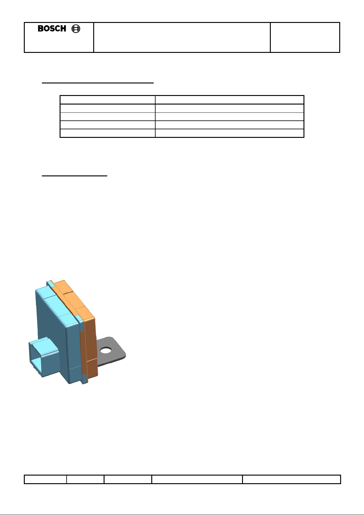
3.1.1.1 Model : Proposed Smartra3
This design will use a different microcontroller with on board non-volatile memory and combined voltage
regulator and LIN transceiver system basis chip.
Issue Number:
© THIS DRAWING IS THE EXCLUSIVE PROPERTY OF ROBERT BOSCH (AUSTRALIA) PTY. LTD. WITHOUT THEIR CONSENT IT MAY NOT BE REPRODUCED OR GIVEN TO THIRD PARTIES.
1.0 Dev No. 3881
Valid from:
14/2/06
Print Date:
28 March, 2007
DEV04205.9/I-1
ROBERT BOSCH
-
(AUSTRALIA) PTY. LTD.
A.B.N. 48 004 315 628
PROTOCOL SPECIFICATION
SMARTRA III IMMOBILISER Page 6 of 49
F005VP0801
3.1.2 Document description
This document shall focus on the communications protocol between the Smartra and the Engine
Management System (EMS). The existing protocol has been used with two new messages added and
existing messages modified. The changes are required due to additional customer requirements.
The document shall present:
• Project background, requirements and proposed design.
• Message Structure between the EMS and Smartra.
• Message Flow charts: EMS to Transponder (via Smartra) considering different device states.
• Replacing immobiliser system components
• Diagnostic tester interface.
3.1.3 Diagram: Smartra communications interfaces
Transponder Smartra
Low Frequency
w ireless link
125kHz ASK
single wire
asynch bi-dir
comms
4800baud
This docume nt
focusses on Smartra
to EMS interface
EMS
(comms master)
Issue Number:
© THIS DRAWING IS THE EXCLUSIVE PROPERTY OF ROBERT BOSCH (AUSTRALIA) PTY. LTD. WITHOUT THEIR CONSENT IT MAY NOT BE REPRODUCED OR GIVEN TO THIRD PARTIES.
1.0 Dev No. 3881
Valid from:
14/2/06
Print Date:
28 March, 2007
DEV04205.9/I-1
ROBERT BOSCH
(AUSTRALIA) PTY. LTD.
A.B.N. 48 004 315 628
PROTOCOL SPECIFICATION
SMARTRA III IMMOBILISER Page 7 of 49
F005VP0801
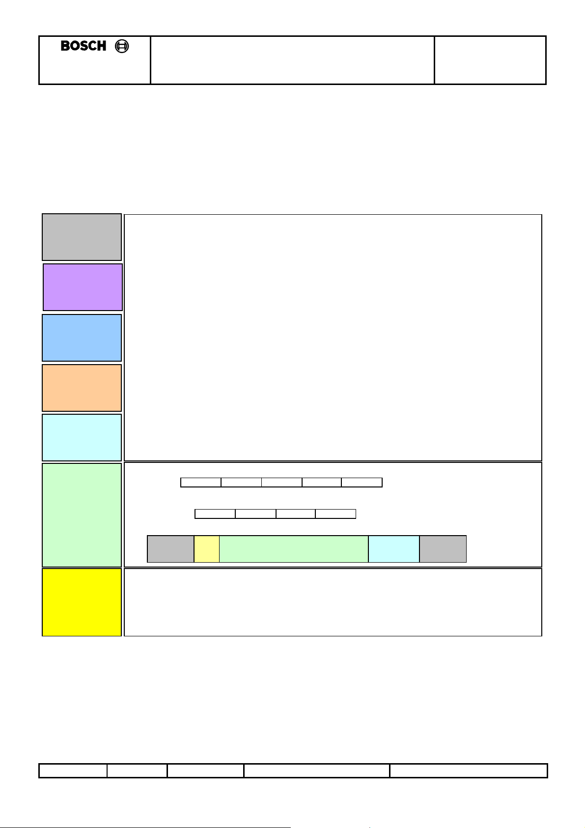
3.2 EMS to Smartra Communications Description (OSI model):
The communications between the EMS and the Smartra can be better described using the 7 layer OSI
model. The below diagram shows different levels of the interface in reference to the OSI model. It
describes the Physical layer the Data Link Layer and the Application Layer.
3.2.1 Diagram: OSI model
Application
Layer
Presentation
Layer
Session
Layer
Transport
Layer
Network
Layer
Data Li nk
Layer
Physical
Layer
EM S Action Messages:
06h (ACK) Acknowledge
53h (ASCII 'S') Software version
4Bh (ASCII 'K') Transponder I DE *
41h (ASCII 'A') Transponder Authentication (Additional info for I D Matching)
57h (ASCII 'W') Transponder Write EEPROM page
52H (ASCII 'R') Transponder Read EEPROM page
4Eh (ASCII ‘N’) Neutralise a Taught Smartra **
54h (ASCII ‘T’) Teach Smartra **
15h (ASCII nak) Negative response *
For every me ssage sent to the SMARTRA from the CU there w ill be a response from the
SMARTRA unit. Only one command can be sent at a time to the SMARTRA unit.
A negative response to any command is possibl e .
* - modif ied message
** - new message
The protocol between the Control Unit (CU) and the SMARTRA is defined as :-
Address Length Action Data CS
The protocol between the SMARTRA and the CU is defined as :-
1 start bit-low, 8 data bits, no parity, 2 stop bits-high.
Idle Start
Address Length Data CS
Data
Bit 1
8 bits
S top bit
2 bits
Idle
Dedicated single wire bet ween Immobiliser and Contr ol Unit.
Bi-directional
Asynchronous
Communications @ 4800 baud
Logic Low = 0 V, Logic High = 12V, Idle State High
Issue Number:
© THIS DRAWING IS THE EXCLUSIVE PROPERTY OF ROBERT BOSCH (AUSTRALIA) PTY. LTD. WITHOUT THEIR CONSENT IT MAY NOT BE REPRODUCED OR GIVEN TO THIRD PARTIES.
1.0 Dev No. 3881
Valid from:
14/2/06
Print Date:
28 March, 2007
DEV04205.9/I-1
ROBERT BOSCH
(AUSTRALIA) PTY. LTD.
A.B.N. 48 004 315 628
PROTOCOL SPECIFICATION
SMARTRA III IMMOBILISER Page 8 of 49
F005VP0801
3.2.1.1 Requirements from customer
Requirements for the new Smartra:
• automobile to be Thatcham Compliant to withstand attack on car for >300secs.
• Product required to be backward compatible with existing system.
Current system :
• Engine Management System (EMS) ECU can be replaced easily and car can be started <300secs
with matching transponders.
• Smartra is transparent ie. passes messages to and from the EMS and transponder (no memory).
3.2.2 Proposed Solution
• To meet new customer requirements the EMS and the Smartra shall be matched together using the
same Secret Encryption Key (SEK).
• The Secret Encryption Key (SEK) is generated and taught to the Smartra and EMS at the OEM end
of line tester.
• The EMS and Smartra will generate the Secret Encryption Key (SEK) from a common 9 byte
Diagnostic PIN Number (DPN) unique for each car (ie. use 6 bytes from Diagnostic PIN Number
(DPN)). See section 3.2.6.
• The Secret Encryption Key (SEK) will be used during all communications between the EMS and the
Smartra to ensure that the EMS and Smartra are matched.
• To test if the units are matched:
o The EMS generates a Random Number and passes to the Smartra.
o Smartra encrypts the Random Number using the Secret Encryption Key(SEK) and passes
back the encrypted value to the EMS.
o EMS encrypts the random number using its Secret Encryption Key(SEK) and then evaluates
if the Smartra response is the same as the EMS encryption.
• Thieves need to replace the EMS, Smartra and Transponder to steal the car. The Smartra shall be
placed in a difficult to get to position in the car (increase time to replace).
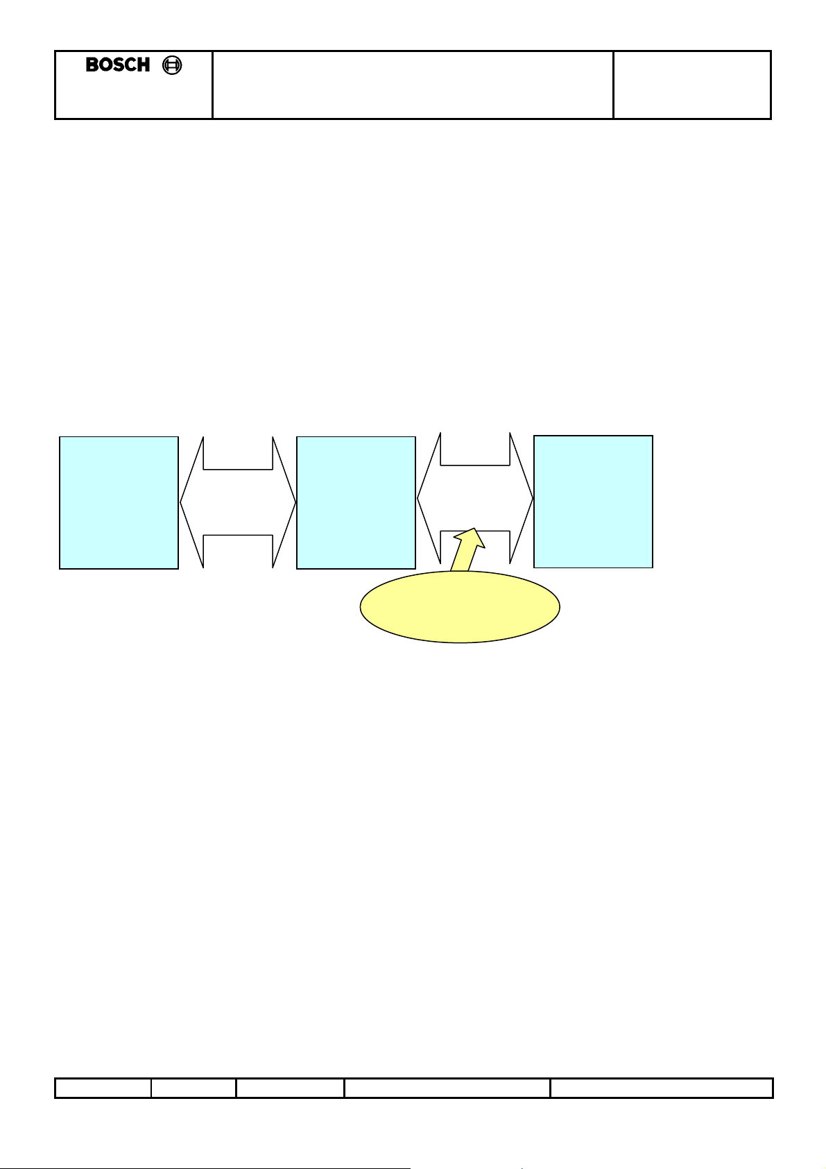
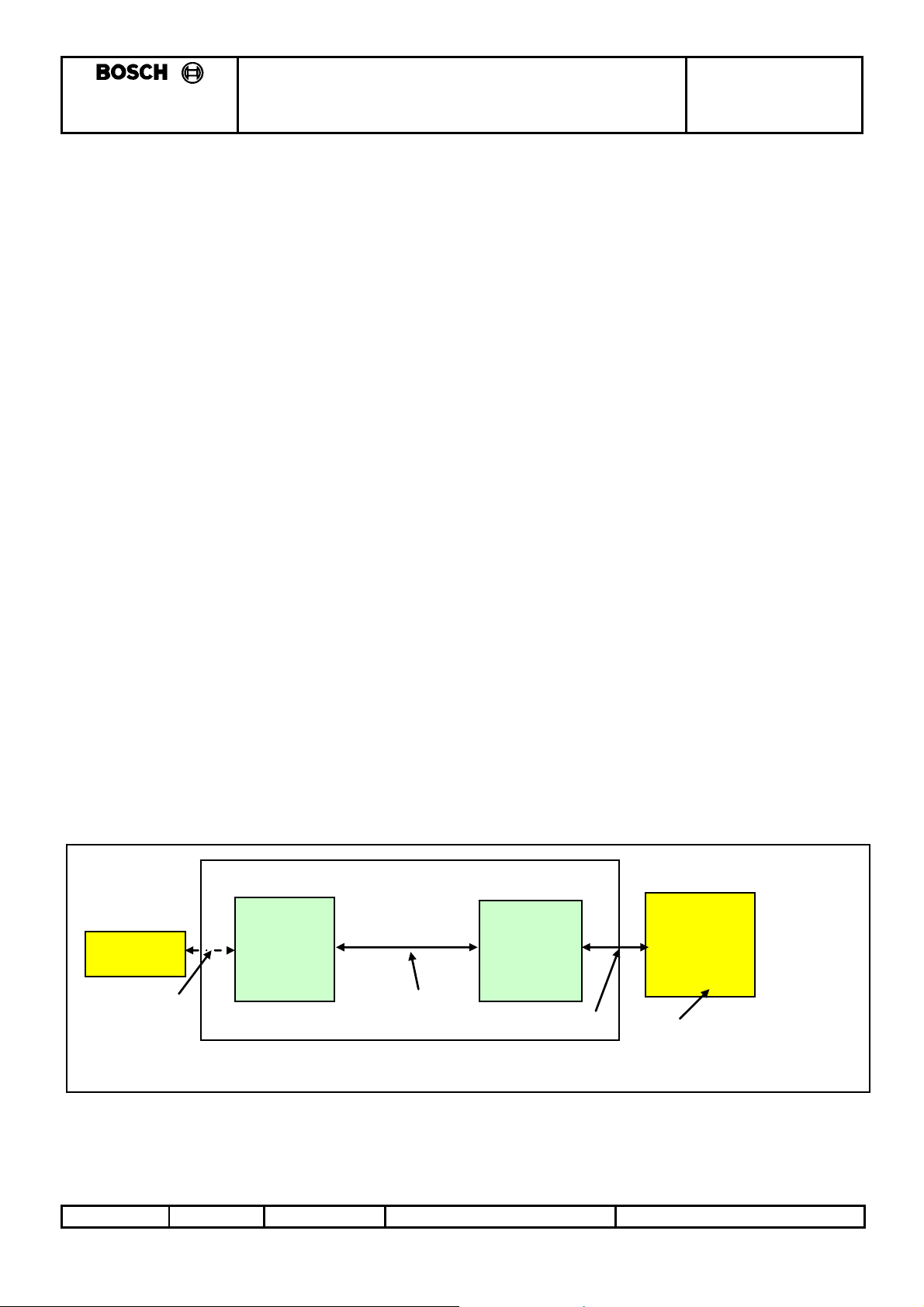
3.2.3 Diagram Showing Proposed Design:
SM ARTRA
transponder
LF interface
Issue Number:
© THIS DRAWING IS THE EXCLUSIVE PROPERTY OF ROBERT BOSCH (AUSTRALIA) PTY. LTD. WITHOUT THEIR CONSENT IT MAY NOT BE REPRODUCED OR GIVEN TO THIRD PARTIES.
1.0 Dev No. 3881
Automobile Assy
Single Wire
Comms
Valid from:
EMS
Single Wire
14/2/06
Comms
Diagnostic
Tester
Securit y Pin No. to access the
EM S and Smartra
Print Date:
28 March, 2007
DEV04205.9/I-1
ROBERT BOSCH
(AUSTRALIA) PTY. LTD.
A.B.N. 48 004 315 628
PROTOCOL SPECIFICATION
SMARTRA III IMMOBILISER Page 9 of 49
F005VP0801
3.2.4 States of the smartra
With the new proposed Design the Smartra shall have 3 states ([Virgin] and [Neutral] states behave the
same).
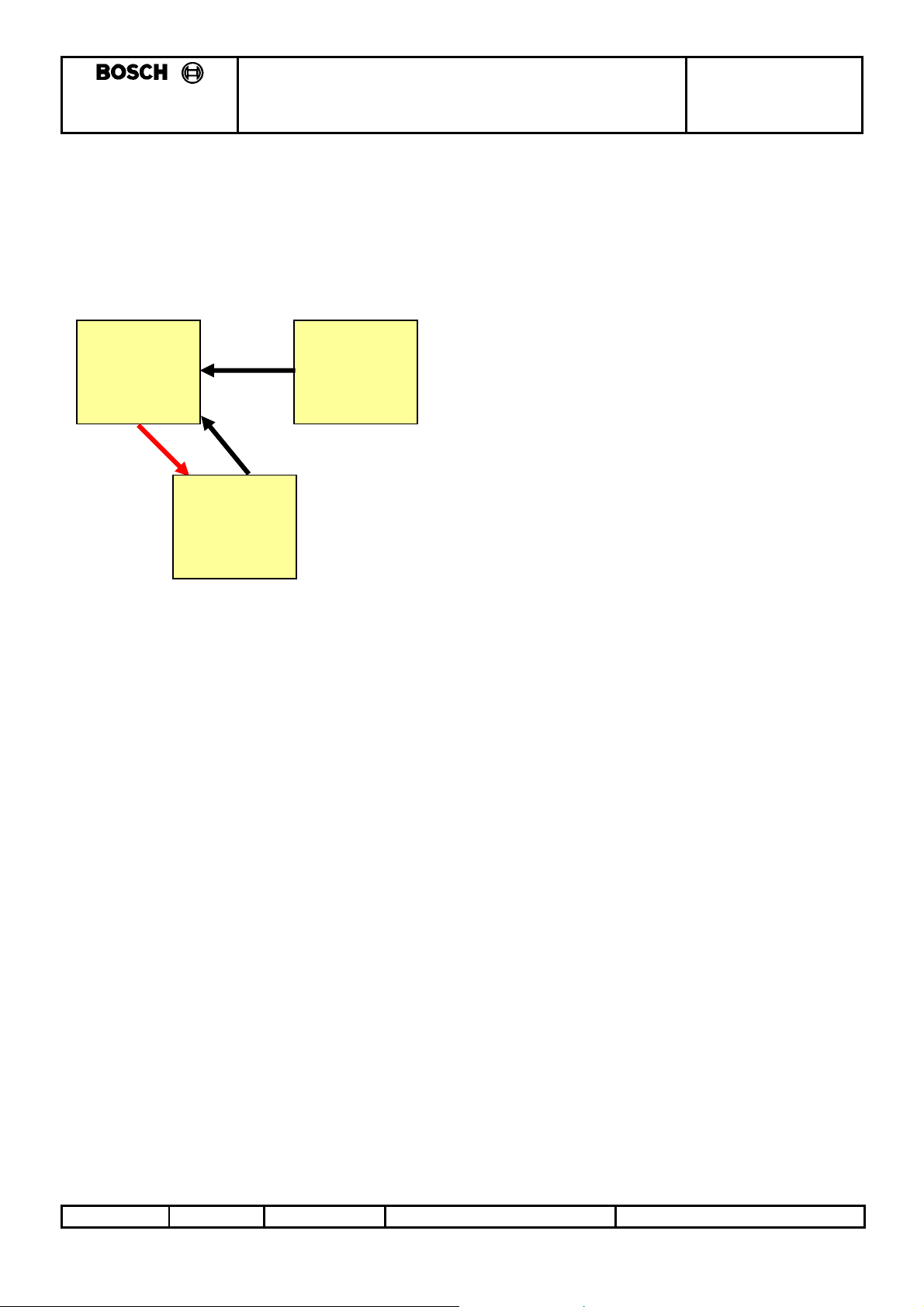
3.2.4.1 State transition Diagram:
Learnt
(follows new
protocol-
Smartra3)
2
Neutral
(follows old
protocol-
Smartra2)
1
1
Virgin
(follows old
protocol-
Smartra2)
3.2.4.1.1 States:
[Virgin] – virgin product after EOL testing.
[Neutral] – part has Diagnostic PIN Number(DPN) and Secret Encryption Key(SEK) cleared using
diagnostic tester so it can go into [Learnt] state again.
[Learnt] – part has been taught a Diagnostic PIN Number(DPN) at the OEM end of line tester or
using diagnostic tester in the field. Secret Encryption Key(SEK) is generated from the
Diagnostic PIN Number(DPN). (refer to 3.2.6)
3.2.4.1.2 State Transitions:
1) Smartra is taught the Diagnostic PIN Number(DPN) and generates the Secret Encryption Key(SEK).
2) Diagnostic Tester Places Smartra into Neutral Mode when correct DPN has been entered.
* Note : For backwards compatibility a [virgin] or [neutral] Smartra3 will function as a Smartra2 until unit
is placed into [learnt] state.
Issue Number:
© THIS DRAWING IS THE EXCLUSIVE PROPERTY OF ROBERT BOSCH (AUSTRALIA) PTY. LTD. WITHOUT THEIR CONSENT IT MAY NOT BE REPRODUCED OR GIVEN TO THIRD PARTIES.
1.0 Dev No. 3881
Valid from:
14/2/06
Print Date:
28 March, 2007
DEV04205.9/I-1
ROBERT BOSCH
r
-
(AUSTRALIA) PTY. LTD.
A.B.N. 48 004 315 628
PROTOCOL SPECIFICATION
SMARTRA III IMMOBILISER Page 10 of 49
F005VP0801
3.2.5 System security
If a thief replaces the Smartra with a virgin Smartra the car will not start as the virgin Smartra does not
match the EMS.
If a thief replaces three components with a matching set (Transponder, Smartra and EMS) then by
breaking lock barrel the car can start. The car will start however the period of time to replace the
Smartra takes time ie. longer than 5 minutes to pass the Thatcham attack test. Refer to section 3.4 –
References.
A thief could steal a car in a short time if they have access to a Diagnostic Tester and a ECU with his
corresponding Diagnostic PIN Number (DPN) then the thief can steal the car by:
a. replacing the EMS with a matching EMS and transponder set.
b. use Diagnostic Tester to neutralise the Smartra3, using the secure HMC Diagnostic PIN Number
(DPN) of EMS.
c. use Diagnostic Tester to program the new Diagnostic PIN Number (DPN) that matches the thiefs
EMS Diagnostic PIN Number (DPN).
The security of the system depends on the security of the DPN.
3.2.6 Secret Encryption Key (SEK) Learning
• The EMS and Smartra will generate the Secret Encryption Key (SEK).
• Secret Encryption Key (SEK) is generated from the first 6 bytes of the 9 byte Diagnostic PIN Number
(DPN).
• The DPN is taught to the Smartra and EMS at the OEM end of line tester or in the field.
• The encryption algorithm requires each of the 6 SEK bytes to be an uneven number between 3 and
253.
o Therefore both the EMS and Smartra will use the same function that will check value of PIN
and adjust each byte of the Secret Encryption Key (SEK) accordingly:
• If DPN byte is <3 or >253 then SEK byte = 0x55.
• Else If DPN byte is even then SEK byte = DPN byte – 1.
• Else SEK byte = DPN byte.
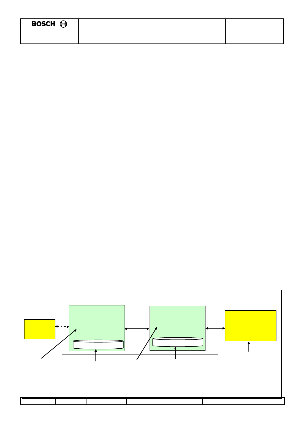
3.2.6.1 Diagram: Secret Key learning flow
Transponder
Secret Encrytpion
Key (SEK) (6 bytes)
generated from
Diagnostic PIN
Number (DPN)
SM ARTR A
0 xXXXXXXXXXXX
0 xXXXXXXXXXXXXXXXX
Diagnostic PIN (9
bytes) number
stored in eeprom
on Smartra
Automobile Assy
0 xXXXXXXXXXXX
0 xXXXXXXXXXXXXXXXX
Secret Encrytp ion
Key (SEK) (6
bytes) - generated
from Diagnostic
PIN Number (DPN)
EMS
Diagnostic PIN 9
byte number
stored in eeprom
on EMS
Diagnos ti c Test e
0 xXXXXXXXXXXXXXXXX
OEM end of line tester
shall generate a
Diagnostic Security Pin
N umber and pass the
number to the EMS.
Issue Number:
© THIS DRAWING IS THE EXCLUSIVE PROPERTY OF ROBERT BOSCH (AUSTRALIA) PTY. LTD. WITHOUT THEIR CONSENT IT MAY NOT BE REPRODUCED OR GIVEN TO THIRD PARTIES.
1.0 Dev No. 3881
Valid from:
14/2/06
Print Date:
28 March, 2007
DEV04205.9/I-1

ROBERT BOSCH
(AUSTRALIA) PTY. LTD.
A.B.N. 48 004 315 628
PROTOCOL SPECIFICATION
F005VP0801
SMARTRA III IMMOBILISER Page 11 of 49
Issue Number:
© THIS DRAWING IS THE EXCLUSIVE PROPERTY OF ROBERT BOSCH (AUSTRALIA) PTY. LTD. WITHOUT THEIR CONSENT IT MAY NOT BE REPRODUCED OR GIVEN TO THIRD PARTIES.
1.0 Dev No. 3881
Valid from:
14/2/06
Print Date:
28 March, 2007
DEV04205.9/I-1

ROBERT BOSCH
(AUSTRALIA) PTY. LTD.
A.B.N. 48 004 315 628
PROTOCOL SPECIFICATION
SMARTRA III IMMOBILISER Page 12 of 49
F005VP0801
3.3 Assumptions Made
o PIN number database (PIN for diagnostic interface) shall be maintained and protected by the
OEM and this information is not information that a thief can access.
3.4 References
HMC Engineering Spec: No ES95400-09 TITLE: IMMOBILIZER SYSTEM FUNCTIONS,
Spec (Encypted Smartra3 Type), VERSION D3, 29/06/2006
Thatcham NVSA specification: No TQSD 014.07 TITLE: THE BRITISH INSURANCE INDUSTRIES
CRITERIA FOR VEHICLE SECURITY, NEW VEHICLE SECURITY ASSESSMENT – PASSENGER
CARS, ISSUE 4A, JULY 2006
Issue Number:
© THIS DRAWING IS THE EXCLUSIVE PROPERTY OF ROBERT BOSCH (AUSTRALIA) PTY. LTD. WITHOUT THEIR CONSENT IT MAY NOT BE REPRODUCED OR GIVEN TO THIRD PARTIES.
1.0 Dev No. 3881
Valid from:
14/2/06
Print Date:
28 March, 2007
DEV04205.9/I-1

ROBERT BOSCH
(AUSTRALIA) PTY. LTD.
A.B.N. 48 004 315 628
PROTOCOL SPECIFICATION
SMARTRA III IMMOBILISER Page 13 of 49
F005VP0801
4. MESSAGE STRUCTURE BETWEEN EMS AND SMARTRA
The proposal for the message structure between the Smartra and the EMS is based on the existing
communications protocol with two additional messages and some modified existing messages. The new
messages and modifications are highlighted in yellow.
4.1.1 Data Packet Breakdown
The protocol between the Control Unit (CU) [EMS] and the SMARTRA is defined as :-
Address Length Action Data CS
length
checksum
The protocol between the SMARTRA and the CU is defined as :-
Address Length Data CS
length
checksum
where :-
Address = 49h (ASCII 'I') when CU is addressing SMARTRA.
= 69h (ASCII 'i') when SMARTRA is addressing CU
Length = number of bytes following the Length byte (including checksum)
Action = valid SMARTRA actions are :-
06h (ACK) Acknowledge
53h (ASCII 'S') Software version
4Bh (ASCII 'K') Transponder IDE*
41h (ASCII 'A') Transponder Authentication (Additional info for ID Matching)
57h (ASCII 'W') Transponder Write EEPROM page
52H (ASCII 'R') Transponder Read EEPROM page
4Eh (ASCII ‘N’) [Neutralise] a [Learnt] Smartra**
54h (ASCII ‘T’) Teach a Smartra**
15h (ASCII nak) Negative response*
Note: * Modified existing message.
** New messages added.
Data = data to be exchanged between units.
CS = Checksum - one byte addition of all bytes (excluding address).
The ASCII code naming convention was carried over from existing protocol.
For every message sent to the SMARTRA from the CU there will be a response from the SMARTRA
unit. Only one command can be sent at a time to the SMARTRA unit.
A negative response to any command is possible and is defined in Section 4.10.
Issue Number:
© THIS DRAWING IS THE EXCLUSIVE PROPERTY OF ROBERT BOSCH (AUSTRALIA) PTY. LTD. WITHOUT THEIR CONSENT IT MAY NOT BE REPRODUCED OR GIVEN TO THIRD PARTIES.
1.0 Dev No. 3881
Valid from:
14/2/06
Print Date:
28 March, 2007
DEV04205.9/I-1

ROBERT BOSCH
(AUSTRALIA) PTY. LTD.
A.B.N. 48 004 315 628
PROTOCOL SPECIFICATION
SMARTRA III IMMOBILISER Page 14 of 49
F005VP0801
4.2 06h - Acknowledge.
CU Request :-
49 02 06 08
SMARTRA Response :-
69 02 06 08
If the SMARTRA unit does not respond to this command then it will not be ready to accept other
communications. This command could be used to determine if the SMARTRA is ready to receive data at
the start of a communications session.
SMARTRA will take up to 5ms to start sending return Acknowledge to the CU.
4.3 53h - Software Version.
CU Request :-
49 02 53 55
SMARTRA Response :-
69 06 Software version in ASCII CS
eg. For software version A01.0 :-
69 06 41 30 31 2E 30 06
Note :- SMARTRA will take up to 5ms to start sending return Software Version to the CU.
Issue Number:
© THIS DRAWING IS THE EXCLUSIVE PROPERTY OF ROBERT BOSCH (AUSTRALIA) PTY. LTD. WITHOUT THEIR CONSENT IT MAY NOT BE REPRODUCED OR GIVEN TO THIRD PARTIES.
1.0 Dev No. 3881
Valid from:
14/2/06
Print Date:
28 March, 2007
DEV04205.9/I-1

ROBERT BOSCH
(AUSTRALIA) PTY. LTD.
A.B.N. 48 004 315 628
PROTOCOL SPECIFICATION
SMARTRA III IMMOBILISER Page 15 of 49
F005VP0801
4.4 4Bh - Transponder IDE (Pre ID Matching)
4.4.1 0x4B – (Existing) Pre Secret Encryption Key – kept for backwards compatibility
CU Request :-
49 02 4B 4D
SMARTRA2 Response:-
69 05 IDE1 IDE2 IDE3 IDE4 Checksum
IDE1..IDE4 :- 32 bit Identifier.
4.4.2 0x4B – New – Secret Encryption Key – with Encryption check.
CU Request :-
49 08 4B
RN1..RN6 :- Random Number bytes (00-FF)
Note :- RN1..6 can be based on the 4 byte random number from the Transponder Authentication
command (refer to “4.5 Transponder Authentication”). This will avoid extra EMS processing to generate
a random number.
SMARTRA3 Response:-
69 0D Return IDE1 IDE2 IDE3 IDE4 ERN1 ERN2 ERN3 ERN4 ERN5 ERN6 Smartra
Return :- 0x00 = transponder communications OK
0x01 = transponder missing or incorrect communications
0x02 = Antenna coil Open/Short Detection
IDE1..IDE4 :- 32 bit Identifier.
ERN1 .. ERN6 :- Encrypted Random Number using Secret Encryption Key (SEK)
Smartra State :- 0x01 = Learnt / Taught
0x02 = Virgin
0x03 = Neutral
Note : - SMARTRA will take up to 110ms to start sending IDE response to the CU.
- When Transponder is missing the Return value will be 0x01 and IDE1 to IDE4 = (0x00 0x00
0x00 0x00).
- When Smartra3 receives the IDE request with the Random Number and it is in:
• [virgin] or [neutral] state the ERN1..6 shall be the encrypted random number using a
default key.
• [learnt] state the ERN1..6 shall be the encrypted random number using the Secret
Encryption Key (SEK).
- Default encryption key will be described in Encryption Software Integration Document.
RN1 RN2 RN3 RN4 RN5 RN6 CS
CS
State
Issue Number:
© THIS DRAWING IS THE EXCLUSIVE PROPERTY OF ROBERT BOSCH (AUSTRALIA) PTY. LTD. WITHOUT THEIR CONSENT IT MAY NOT BE REPRODUCED OR GIVEN TO THIRD PARTIES.
1.0 Dev No. 3881
Valid from:
14/2/06
Print Date:
28 March, 2007
DEV04205.9/I-1

ROBERT BOSCH
(AUSTRALIA) PTY. LTD.
A.B.N. 48 004 315 628
PROTOCOL SPECIFICATION
SMARTRA III IMMOBILISER Page 16 of 49
F005VP0801
4.5 41h - Transponder Authentication.
CU Request :-
49 0A 41 RN1 RN2 RN3 RN4 ELP1 ELP2 ELP3 ELP4 CS
RN1..RN4 :- Random Number bytes (00-FF)
ELP1.. ELP4 :- Encrypted Lock Password bytes (00-FF)
SMARTRA Response :-
69 05 EKP1 EKP2 EKP3 EKP4 CS
EKP1 .. EKP4 :- Encrypted Key Password bytes (00-FF)
Note :- SMARTRA will take up to 150ms to start sending the Authentication response to the CU.
4.6 57h - Transponder Write EEPROM Page.
CU Request :-
49 Length 57 PN B0 B1 B2 B3 PNn B0n B1n B2n B3n CS
PN...PNn :- Page Number byte (01-07)
B0,B1,B2,B3...B0n,B1n,B2n,B3n :- Transponder bytes to be written (00-FF)
SMARTRA Response :-
69 02 57 59
This request is only valid during the key programming procedure with the Transponder in password
mode.
Note :-
• SMARTRA will take up to 600ms to start sending the response to the CU when programming three
consecutive pages.
• Maximum number of consecutive pages to program in the same “Transponder Write EEPROM Page”
request is three.
4.7 52h - Transponder Read EEPROM Page
CU Request :-
49 03 52 PN CS
PN :- Page Number byte (00-07)
SMARTRA Response :-
69 05 B0 B1 B2 B3 CS
B0 .. B3 :- Transponder bytes read (00-FF)
This request is only valid prior to key programming procedure with the Transponder in password mode.
Note :- SMARTRA will take up to 100ms to start sending the response bytes to the CU.
Issue Number:
© THIS DRAWING IS THE EXCLUSIVE PROPERTY OF ROBERT BOSCH (AUSTRALIA) PTY. LTD. WITHOUT THEIR CONSENT IT MAY NOT BE REPRODUCED OR GIVEN TO THIRD PARTIES.
1.0 Dev No. 3881
Valid from:
14/2/06
Print Date:
28 March, 2007
DEV04205.9/I-1

ROBERT BOSCH
(AUSTRALIA) PTY. LTD.
A.B.N. 48 004 315 628
PROTOCOL SPECIFICATION
SMARTRA III IMMOBILISER Page 17 of 49
F005VP0801
4.8 4Eh – Neutralise a [Learnt] Smartra
Message is instigated by Diagnostic Tester and passed to the Smartra through the EMS. The Smartra
will check if the DPN is correct before changing to [neutral] state.
CU Request :We request to place Smartra into Neutral Mode:
49 0B 4E DPN1 DPN2 DPN3 DPN4 DPN5 DPN6 DPN7 DPN8 DPN9 C
S
DPN1..9 - Diagnostic PIN Number byte 1 to 9
SMARTRA Response :-
69 02 Return CS
Return = 0x01 = Correct PIN changed from [Learnt] to [Neutral]
0x02 = Correct PIN already in Virgin State
0x03 = Correct PIN already in Neutral State
0x04 = Diagnostic PIN incorrect
Note :-
-The EMS will pass this information to the Diagnostic Tester.
4.9 54h – Teach Smartra
Message is instigated by EMS when the Smartra State is [Virgin] or [Neutral] and if the Diagnostic Tester
wants to teach the Diagnostic PIN Number.
CU Request :-
49 0B 54 DPN1 DPN2 DPN3 DPN4 DPN5 DPN6 DPN7 DPN8 DPN9 CS
DPN1..9 - Diagnostic PIN Number byte 1 to 9
SMARTRA Response :-
69 02 Return CS
Return = 0x01 – Programmed Successfully
= 0x02 – Correct PIN (Smartra already in Learnt State).
= 0x03 – Incorrect PIN
**Note**:
1) For backward compatibility the Smartra3 will by default function as a Smartra2 until the Teach Smartra
command is completed correctly.
2) When Smartra3 handles this message it shall convert the diagnostic PIN number to a secret KEY and
store it on the device.
Issue Number:
© THIS DRAWING IS THE EXCLUSIVE PROPERTY OF ROBERT BOSCH (AUSTRALIA) PTY. LTD. WITHOUT THEIR CONSENT IT MAY NOT BE REPRODUCED OR GIVEN TO THIRD PARTIES.
1.0 Dev No. 3881
Valid from:
14/2/06
Print Date:
28 March, 2007
DEV04205.9/I-1

ROBERT BOSCH
(AUSTRALIA) PTY. LTD.
A.B.N. 48 004 315 628
PROTOCOL SPECIFICATION
SMARTRA III IMMOBILISER Page 18 of 49
F005VP0801
4.10 15h - Negative Responses
To any CU command the SMARTRA may respond negatively. The following message will be sent.
SMARTRA Negative Response (NAK) :-
69 03 15 Error code CS
Error Code Description
01h Antenna signal error
Detection Window : Before transponder communications
Detection Criteria : Antenna open/short circuit
02h Invalid Transponder Data
Detection Window :- a. During Transponder IDE
b. During Transponder Authentication requests
c. During Transponder Write EEPROM page requests.
d. During Transponder Read EEPROM page requests.
Detection Criteria :- Corrupted data from Transponder (Tp), or more than one Tp in
the field, or no Tp in the field.
03h Request from Control unit is invalid
Detection Window :- End of CU request message
Detection Criteria :- Protocol layer violation -- Invalid request,
--or invalid check sum,
04h Password mode invalid
Detection Window :- During Transponder Write or Read EEPROM Page
Detection Criteria :- Tp not in password mode, or Transponder transport data has
been changed.
05h Smartra in locked state:
Detection Window :- During access to the Diagnostic functions, teaching or
neutralising a Smartra.
Detection Criteria :- When the DPN is entered while the Smartra is locked.
Refer to section 7.1.6.
1PNh
PN = page No. failed
PN = 1..7
Transponder Programming error
Detection Window :- During Transponder Write EEPROM Page request While
Transponder is in authorised state.
Detection Criteria :- Corrupted data from Transponder (Tp), Or more than one Tp in
the field, or no Tp in the field.
Issue Number:
© THIS DRAWING IS THE EXCLUSIVE PROPERTY OF ROBERT BOSCH (AUSTRALIA) PTY. LTD. WITHOUT THEIR CONSENT IT MAY NOT BE REPRODUCED OR GIVEN TO THIRD PARTIES.
1.0 Dev No. 3881
Valid from:
14/2/06
Print Date:
28 March, 2007
DEV04205.9/I-1

ROBERT BOSCH
(AUSTRALIA) PTY. LTD.
A.B.N. 48 004 315 628
PROTOCOL SPECIFICATION
SMARTRA III IMMOBILISER Page 19 of 49
F005VP0801
5. MESSAGE FLOW BETWEEN EMS, SMARTRA AND TRANSPONDER
5.1 Background
The message flow between the Smartra and the EMS is described in the following section. The Smartra
is event driven ie. the EMS sends a message, the Smartra response will be sent back to the EMS.
Components missing in system:
If no EMS is present then the Smartra does nothing.
If no Smartra is present the EMS will timeout on the ACK request message.
If no transponder is present the Smartra will send a NAK to the EMS (No transponder).
5.1.1 Starting Communications
The communications start with Ignition switch ON or Key Teaching Mode(14h) and ignition switch ON.
5.1.2 Stopping Communications
The communications stop when:
• no response received from Smartra after EMS attempts to send a message to the Smartra
more than 3 times.
• communication error on Smartra when an EMC or checksum error occurs more than 3 times.
• Authentication is complete. Note in case of ignition off by key before authentication EMS
should not store error.
5.1.3 (Re)Teaching Mode
• EMS should not start communication request (06h/4Bh/…) after IGN ON by Next Key,
• and in case of sending Teaching messages(1Ch…1Eh) from Tester(HI-SCAN or GST) EMS
should start communication request (06h/4Bh/…).
5.1.3.1 Diagram: Explaining how to read message flow diagrams
Transponder
Solid Lines show
modules that send and
receive data
Block indicates some
processing at module
Smartra EMS
IDE Request
0x49 S 0x4B RN1..6
response pair,
grouped to
make reading
Arro w Shows Direction
of message
Message structure, data
that makes message.
Yellow = new message
Blue = existing message
Red = error message
Request
easier
Issue Number:
© THIS DRAWING IS THE EXCLUSIVE PROPERTY OF ROBERT BOSCH (AUSTRALIA) PTY. LTD. WITHOUT THEIR CONSENT IT MAY NOT BE REPRODUCED OR GIVEN TO THIRD PARTIES.
1.0 Dev No. 3881
Valid from:
14/2/06
Print Date:
28 March, 2007
DEV04205.9/I-1

ROBERT BOSCH
(AUSTRALIA) PTY. LTD.
A.B.N. 48 004 315 628
PROTOCOL SPECIFICATION
SMARTRA III IMMOBILISER Page 20 of 49
F005VP0801
5.2 Message Flow 1 - Normal Operation
Authentication Flow : After ignition or accessories is detected by the CU (EMS) the following steps will
normally be taken to validate the key. We have not added any new messages in the flow only
increased some message sizes.
1) CU provides supply voltage to SMARTRA.
2) CU sends command 06h – ACK.
3) SMARTRA3 responds with 06h – ACK.
4) CU sends command 4Bh - Transponder IDE (+ random number(6 bytes) ).
5) SMARTRA3 responds with the transponder's Identifier (32 bits) [+ Return byte + encrypted number (6bytes) +State(1byte) ].
6) CU sends command 52h – Read EEPROM Page.
7) SMARTRA3 responds with 15h Negative Response. This indicates to EMS that Transponder is in learnt state.
8) The CU generates a random number and calculates the encrypted lock password, then sends command 41h - Transponder
Authentication.
9) SMARTRA3 responds with the encrypted key password.
10) The CU compares the encrypted key password from the transponder (via SMARTRA) with its calculated encrypted key password, if they
match then the key has been authenticated.
5.2.1.1 Message Sequence
Command 06h 53h 4Bh 41h 52h 57h 4Eh 54h 15h
Sequence 1 -
2
4 3 - - - -
5.2.1.2 Message Flow Detail
Msg
TP SM EMS Mode
Flow
no.
L L L Normal
1
description
message Flow
All modules
learnt. Same
as Flow 9.
Description
EMS message
ACK request
IDE request
Read EEPROM
Authentication req
5.2.2 Message Flow Diagram:
Transponder[learnt] Smart ra[learnt ]
Smartra3 responds
with a ACK
Smartra kno ws the EM S sw
is new versio n d ue t o extra
bytes - encrypts RN1..4 and
passe s to EMS
IDE request
Read EEPROM Page
Smar tra does tra nsponder
encryption
Smartra send s
encrypted data
Authentication
ACK request
0x49 0x 0 2 0x06 0x08
0x69 0x02 0x06 0x08
0x49 S 0x4B + RN1..6
0x69 S Ret IDE1..4 +
ERN1..6 + State byte
0x49 S 0x52 PAGE
0x69 0 x15 error
0x49 S 0x41 RN1..4
message
ELP1..4
0x69 S EKP1..4
Data EMS message Description
Smartra Response
0x49 0x02 0x06 0x08
0x49 S 0x4B RN1..6
0x49 S 0x52 PAGE
0x49 S 0x41 RN1..4
ELP1..4
EM S[ learnt]
EMS request s ACK
EMS receives ACK
EMS request s IDE f rom
tra nsponder with 0x4B
+ extra bytes
From IDE response EMS
knows type of Smartra, and
TP IDE.
E MS requests to read e eprom
page
Read EEPROM error
me ssage receive d.
Request the Transponder
Authentication
Evaluate transponder
encrypted key password
if OK then start engine
ACK response
IDE Response
Negative response
Authentication Response
Data Smartra Message
0x49 0x02 0x06 0x08
0x69 S R IDE1..4 + ERN1..6 + State byte
0x69 S 0x15 0xXX
0x69 S EKP1..4
Issue Number:
© THIS DRAWING IS THE EXCLUSIVE PROPERTY OF ROBERT BOSCH (AUSTRALIA) PTY. LTD. WITHOUT THEIR CONSENT IT MAY NOT BE REPRODUCED OR GIVEN TO THIRD PARTIES.
1.0 Dev No. 3881
Valid from:
14/2/06
Print Date:
28 March, 2007
DEV04205.9/I-1

ROBERT BOSCH
K
(AUSTRALIA) PTY. LTD.
A.B.N. 48 004 315 628
PROTOCOL SPECIFICATION
SMARTRA III IMMOBILISER Page 21 of 49
5.3 Message Flow 2 – Twice IG ON or Authentication mode
Transponder is in [Virgin] state read EEPROM is allowed.
5.3.1.1 Message Sequence
Command 06h 53h 4Bh 41h 52h 57h 4Eh 54h 15h
Sequence 1 -
2
- 3 - - - -
5.3.1.2 Message Flow Detail
Msg
TP SM EMS Mode
Flow
no.
V V N V/L/N Twice IG ON
2
description
or
Authentication
Description
EMS message
ACK request
IDE request
Read EEPROM
Data EMS message Description
0x49 0x02 0x06 0x08
0x49 S 0x4B RN1..6
0x49 S 0x52 PAGE
Smartra Response
ACK response
IDE Response
EEPROM data Response
Data Smartra Message
0x49 0x02 0x06 0x08
0x69 S R IDE1..4 + ERN1..6 + State byte
0x69 S B0..3
5.3.2 Message Flow Diagram:
Transponder[virgin]
If IDE request has a Random
Number attached t hen the
Smart ra will send t he new EM S
some more information.
Smart ra3 responds
Smartra[ vir gi n / neutral]
with a ACK
IDE request
Read EEPROM Page
EM S [ virgin, neutral, learnt ]
ACK request
0x49 0x02 0x06 0x08
0x69 0x02 0x06 0x 08
0x49 S 0x4B + RN1..6
0x69 S Ret IDE1..4 +
ERN1..6 + St ate byte
0x49 S 0x52 PAGE
0x69 S B0..3
new EM S req uests AC
EM S receives ACK
EMS requests IDE from
transponder wit h 0x4B
+ extra bytes
From IDE response E MS
knows t ype of Smartra, and
TP I DE.
EM S requests to read
e eprom pa ge
Smart ra sends
response
F005VP0801
Issue Number:
© THIS DRAWING IS THE EXCLUSIVE PROPERTY OF ROBERT BOSCH (AUSTRALIA) PTY. LTD. WITHOUT THEIR CONSENT IT MAY NOT BE REPRODUCED OR GIVEN TO THIRD PARTIES.
1.0 Dev No. 3881
Valid from:
14/2/06
Print Date:
28 March, 2007
DEV04205.9/I-1

ROBERT BOSCH
K
m
(AUSTRALIA) PTY. LTD.
A.B.N. 48 004 315 628
PROTOCOL SPECIFICATION
SMARTRA III IMMOBILISER Page 22 of 49
5.4 Message Flow 3 – Twice IG ON or Authentication mode
Transponder is in [learnt] state Read EEPROM is not allowed.
5.4.1.1 Message Sequence
Command 06h 53h 4Bh 41h 52h 57h 4Eh 54h 15h
Sequence 1 -
2
- 3 - - - 3.5
5.4.1.2 Message Flow Detail
Msg
TP SM EMS Mode
Flow
no.
L V N V/L/N Twice IG ON
3
description
or
Authentication
Description
EMS message
ACK request
IDE request
Read EEPROM
Data EMS message Description
0x49 0x02 0x06 0x08
0x49 S 0x4B RN1..6
0x49 S 0x52 PAGE
Smartra Response
ACK response
IDE Response
EEPROM data Response
Data Smartra Message
0x49 0x02 0x06 0x08
0x69 S R IDE1..4 + ERN1..6 + State byte
0x69 S 0x15 0xXX
5.4.2 Message Flow Diagram:
Tr anspo nder [ lear nt]
Smart r a[vi rg in / neut ral]
ACK request
0x49 0x02 0x06 0x 0 8
Smart ra3 responds
with a ACK
0x69 0 x02 0x06 0x 0 8
EM S [ virgin, neutral, learnt ]
new EM S reque sts AC
EMS receives ACK
F005VP0801
If IDE request has a Random
Number attached then the
Sma rtra will s end the new EMS
some more i nform ation.
Read EEPROM Page
IDE request
0x49 S 0x4B + RN1..6
0x69 S Ret IDE1 ..4 +
ERN1..6 + State byte
0x49 S 0x52 PAGE
0x69 0x15 error
message
EM S requests IDE from
transpon d er with 0x4B
+ extra bytes
From IDE response EMS
knows type of S mar tra, and
TP IDE.
EM S requests to read
eepr om page
Receive negative response fro
Smart ra as Transponder is
already learnt
Issue Number:
© THIS DRAWING IS THE EXCLUSIVE PROPERTY OF ROBERT BOSCH (AUSTRALIA) PTY. LTD. WITHOUT THEIR CONSENT IT MAY NOT BE REPRODUCED OR GIVEN TO THIRD PARTIES.
1.0 Dev No. 3881
Valid from:
14/2/06
Print Date:
28 March, 2007
DEV04205.9/I-1

ROBERT BOSCH
(AUSTRALIA) PTY. LTD.
A.B.N. 48 004 315 628
PROTOCOL SPECIFICATION
SMARTRA III IMMOBILISER Page 23 of 49
5.5 Message Flow 4 - Twice IG ON or Authentication mode
Transponder is in [Virgin] state read EEPROM is allowed.
5.5.1.1 Message Sequence
Command 06h 53h 4Bh 41h 52h 57h 4Eh 54h 15h
Sequence 1 -
2
- 3 - - - -
5.5.1.2 Message Flow Detail
Msg
TP SM EMS Mode
Flow
no.
V L V/L/N Twice IG ON
4
description
or
Authentication
Description
EMS message
ACK request
IDE request
Read EEPROM
Data EMS message Description
0x49 0x02 0x06 0x08
0x49 S 0x4B RN1..6
0x49 S 0x52 PAGE
Smartra Response
ACK response
IDE response
EEPROM data Response
Data Smartra Message
0x49 0x02 0x06 0x08
0x69 S R IDE1..4 + ERN1..6 + State byte
0x69 S B0..3
5.5.2 Message Flow Diagram:
Tr anspo nd er[vi rg i n]
Smartra knows the EMS sw
is new version due to extra
bytes - encrypts RN 1..6 an d
pass es to EMS
Smartra sends the
EEPROM page bytes
Smartr a[ l earnt ]
Sm artra3 responds
with a ACK
IDE request
Read EEPROM Page
AC K request
0x49 0x02 0x06 0x 08
0x69 0x02 0x06 0x 08
0x49 S 0x 4B R N 1..6
0x69 S Ret IDE1..4 +
ERN1. .6 + State byte
0x49 S 0x 52 PAGE
0x69 S B0. .3
EM S [ v i r g i n, l ea r nt , ne ut r a l ]
EMS reque sts ACK
EM S receives ACK
EM S reque sts IDE from
transpon der w i th 0x4B
+ extra byt es
From IDE response EMS
knows type of Smartra, and
TP IDE.
EMS reque sts to read eeprom
page
EMS receives TP
EEPROM data.
F005VP0801
Issue Number:
© THIS DRAWING IS THE EXCLUSIVE PROPERTY OF ROBERT BOSCH (AUSTRALIA) PTY. LTD. WITHOUT THEIR CONSENT IT MAY NOT BE REPRODUCED OR GIVEN TO THIRD PARTIES.
1.0 Dev No. 3881
Valid from:
14/2/06
Print Date:
28 March, 2007
DEV04205.9/I-1

ROBERT BOSCH
(AUSTRALIA) PTY. LTD.
A.B.N. 48 004 315 628
PROTOCOL SPECIFICATION
SMARTRA III IMMOBILISER Page 24 of 49
5.6 Message Flow 5 - Twice IG ON or Authentication mode
Transponder is in [learnt] state Read EEPROM is not allowed.
5.6.1.1 Message Sequence
Command 06h 53h 4Bh 41h 52h 57h 4Eh 54h 15h
Sequence 1 -
2
- 3 - - - 3.5
5.6.1.2 Message Flow Detail
Msg
TP SM EMS Mode
Flow
no.
L L V/N Twice IG ON
5
description
or
Authentication
Description
EMS message
ACK request
IDE request
Read EEPROM
Data EMS message Description
0x49 0x02 0x06 0x08
0x49 S 0x4B DATA
0x49 S 0x52 PAGE
Smartra Response
ACK response
IDE response
Negative response
Data Smartra Message
0x49 0x02 0x06 0x08
0x69 S R IDE1..4 + ERN1..6 + State byte
00x69 S 0x15 0xXX
5.6.2 Message Flow Diagram:
Tr anspo nder[learnt]
Smart ra[learnt]
AC K request
0x49 0x02 0x06 0x08
EM S[vir gin, neutral]
EM S requests ACK
F005VP0801
Smartra3 responds
with a ACK
Smartra knows the EM S sw
is new version due to extra
bytes - en crypts RN1..4 and
passes to EMS
Read EEPROM Page
IDE request
0x69 0x02 0x06 0x08
0x49 S 0x4B RN1. .6
0x69 S Ret IDE1..4 +
ERN1 ..6 + State byte
0x4 9 S 0x52 PAGE
0x69 0x15 error
message
EM S receives ACK
EMS requests IDE from
transponder with 0x4B
+ extra bytes
From IDE response EMS
knows type of S martra, and
TP IDE.
EM S requests to read eeprom
page
Read EEPROM error
m e ssage receive d.
Issue Number:
© THIS DRAWING IS THE EXCLUSIVE PROPERTY OF ROBERT BOSCH (AUSTRALIA) PTY. LTD. WITHOUT THEIR CONSENT IT MAY NOT BE REPRODUCED OR GIVEN TO THIRD PARTIES.
1.0 Dev No. 3881
Valid from:
14/2/06
Print Date:
28 March, 2007
DEV04205.9/I-1

ROBERT BOSCH
(AUSTRALIA) PTY. LTD.
A.B.N. 48 004 315 628
PROTOCOL SPECIFICATION
SMARTRA III IMMOBILISER Page 37 of 49
5.19 Message Flow 18: – Old EMS with a new learnt Smartra
Smartra sends an exsting error message for EMS to handle.
5.19.1.1 Message Sequence
Command 06h 53h 4Bh 41h 52h 57h 4Eh 54h 15h
Sequence 1 -
2
- - - - - 2.5
5.19.1.2 Message Flow Detail
Msg
TP SM EMS Mode
Flow
no.
V
18
L VLN
L
(Old)
description
Old EMS new
learnt smartra
Description
EMS message
ACK request
IDE Request 1
IDE Request 2
IDE Request 3
Data EMS message Description
0x49 0x02 0x06 0x08
0x49 S 0x4B
0x49 S 0x4B
0x49 S 0x4B
Smartra Response
ACK response
IDE Response (Negative)
IDE Response (Negative)
IDE Response (Negative)
Data Smartra Message
0x49 0x02 0x06 0x08
0x69 S 0x15 0x03
0x69 S 0x15 0x03
0x69 S 0x15 0x03
5.19.2 Message Flow Diagram:
Tr anspo nder [ vir gi n , learnt ]
Smartr a[ l earnt ]
Old EM S [virgin, lear nt, neut ral]
F005VP0801
Smartra3 responds
with a ACK
0x69 0x02 0x06 0x 08
IDE request 1
IDE request 2
IDE request 3
ACK request
0x49 0x02 0x06 0x 08
0x49 S 0x4B
0x69 0x15 0X03
err or message
0x49 S 0x4B
0x69 0x15 0X03
err or message
0x49 S 0x4B
EMS request s ACK
EMS receives ACK
EMS request s IDE from
transpon der with 0x4B
+ extra bytes
New Sm artra responds w i th
an exsiting error message
as t he learnt smart ra cant
talk to a O ld EMS .
EMS request s IDE from
transpon der with 0x4B
+ extra bytes
New Smartr a responds
wit h an exsiting error
message as the learnt
smartra cant talk to a Old
EMS.
EMS request s IDE from
transpon der with 0x4B
+ extra bytes
0x69 0x15 0X03
err or message
Issue Number:
© THIS DRAWING IS THE EXCLUSIVE PROPERTY OF ROBERT BOSCH (AUSTRALIA) PTY. LTD. WITHOUT THEIR CONSENT IT MAY NOT BE REPRODUCED OR GIVEN TO THIRD PARTIES.
1.0 Dev No. 3881
Valid from:
14/2/06
New Smartra responds wit h an
exsiting error message as the learnt
smartra cant talk to a Old EM S.
Print Date:
23 March, 2007
DEV04205.9/I-1

ROBERT BOSCH
(AUSTRALIA) PTY. LTD.
A.B.N. 48 004 315 628
PROTOCOL SPECIFICATION
SMARTRA III IMMOBILISER Page 38 of 49
5.20 Message Flow 19: – Old EMS with a virgin Smartra
This combination will function according to the Smartra2 protocol specification.
5.20.1.1 Message Sequence
Command 06h 53h 4Bh 41h 52h 57h 4Eh 54h 15h
Sequence 1 -
2
- - - - - -
5.20.1.2 Message Flow Detail
Msg
TP SM EMS Mode
Flow
no.
L V L
19
(Old)
description
Old EMS with
a virgin
Smartra3
Description
EMS message
ACK request
IDE Request
….
Following
messages are the
same as Smartra2
…….
Data EMS message Description
0x49 0x02 0x06 0x08
0x49 S 0x4B
….
Following messages are the
same as Smartra2
…….
Smartra Response
ACK response
IDE Response
….
Following messages are
the same as Smartra2
…….
Data Smartra Message
0x69 0x02 0x06 0x08
0x69 S IDE1..4
….
Following messages are the same as
Smartra2
…….
5.20.2 Message Flow Diagram:
F005VP0801
Issue Number:
© THIS DRAWING IS THE EXCLUSIVE PROPERTY OF ROBERT BOSCH (AUSTRALIA) PTY. LTD. WITHOUT THEIR CONSENT IT MAY NOT BE REPRODUCED OR GIVEN TO THIRD PARTIES.
1.0 Dev No. 3881
Valid from:
14/2/06
Print Date:
23 March, 2007
DEV04205.9/I-1

ROBERT BOSCH
(AUSTRALIA) PTY. LTD.
A.B.N. 48 004 315 628
PROTOCOL SPECIFICATION
SMARTRA III IMMOBILISER Page 39 of 49
F005VP0801
5.21 Message Flow 20: – Old Smartra with a new EMS
This combination will not allow automobile to start up as the system isn’t setup correctly.
5.21.1.1 Message Sequence
Command 06h 53h 4Bh 41h 52h 57h 4Eh 54h 15h
Sequence 1 -
2
- - - - - -
5.21.1.2 Message Flow Detail
Msg
TP SM EMS Mode
Flow
no.
20
old
L
L Old Smartra
description
with a new
learnt EMS
Description
EMS message
ACK request
IDE Request 1
IDE Request 2
IDE Request 3
Data EMS message Description
Smartra Response
0x49 0x02 0x06 0x08
0x49 S 0x4B RN1..6
0x49 S 0x4B RN1..6
0x49 S 0x4B RN1..6
ACK response
IDE Response 1
IDE Response 2
IDE Response 3
Data Smartra Message
0x69 0x02 0x06 0x08
0x69 S IDE1..4
0x69 S IDE1..4
0x69 S IDE1..4
5.21.2 Message Flow Diagram:
Transponder[learnt] Old Smartra
New EM S[learnt]
Smart ra2 respo nd s
with a ACK
IDE request 1
ACK request
0x49 0x02 0x06 0x08
0x69 0x02 0x06 0x08
0x49 S 0x4B + RN1 ..6
EM S request s ACK
EM S receives ACK
EMS requests IDE from
transpo nd er wit h 0x4 B
+ extra bytes
0x69 S IDE1..4
IDE request 2
0x49 S 0x4B + RN1 ..6
0x69 S IDE1..4
I DE request 3
0x49 S 0x4B + RN1 ..6
EM S knows there is a
Smart ra2 when it is
expecting a Smartra3. Try
again.
EMS requests IDE from
transpo nd er wit h 0x4 B
+ extra bytes
EM S knows there is a
Smart ra2 when it is
expecting a Smartra3. Try
again.
EMS requests IDE fro m
transp o nd er wit h 0x4 B
+ extra bytes
EM S knows there is a
0x69 S IDE1..4
Smart ra2 when it is
expecting a Smartra3. The
EM S needs to raise an error
as there is a miss-match
Messa ge Flow w ill stop as the EMS knows that
there is a Smartra2 in the system when it is
expe cting a configure d Sm artra3.
Issue Number:
© THIS DRAWING IS THE EXCLUSIVE PROPERTY OF ROBERT BOSCH (AUSTRALIA) PTY. LTD. WITHOUT THEIR CONSENT IT MAY NOT BE REPRODUCED OR GIVEN TO THIRD PARTIES.
1.0 Dev No. 3881
Valid from:
14/2/06
Print Date:
23 March, 2007
DEV04205.9/I-1

ROBERT BOSCH
(AUSTRALIA) PTY. LTD.
A.B.N. 48 004 315 628
PROTOCOL SPECIFICATION
SMARTRA III IMMOBILISER Page 40 of 49
F005VP0801
5.22 Summary Tables : Message Flow Summary
Table displays the transponder (TP), Smartra (SM) and engine management system(EMS) states and
the messages that are sent when in the state between the EMS and the Smartra. The message flows
are described in more detail below.
5.22.1 Table: Normal Message Flow
Msg
TP SM EMS Mode
Flow
no.
L L L Normal
1
description
message Flow
All modules
learnt.
Same as Flow
9.
Description
EMS message
ACK request
IDE request
Read EEPROM
Authentication req
Data EMS message Description
Smartra Response
0x49 0x02 0x06 0x08
0x49 S 0x4B RN1..6
0x49 S 0x52 PAGE
0x49 S 0x41 RN1..4
ELP1..4
ACK response
IDE Response
Negative response
Authentication Response
Data Smartra Message
0x49 0x02 0x06 0x08
0x69 S R IDE1..4 + ERN1..6 + State byte
0x69 S 0x15 0xXX
0x69 S EKP1..4
TP = transponder SM = Smartra EMS = engine management system.
V = virgin L = Learnt N = Neutral S = size R = return value D = data M = Missing (old) = Smartra2 compatible EMS unit
Note : ** all messages have Check sum at end but this isn’t shown to simplify matrix.
5.22.2 Table: Twice IG ON or Authentication
Msg
TP SM EMS Mode
Flow
no.
V V N V/L/N Twice IG ON
2
L
3
V N
V L V/L/N Twice IG ON
4
L L V/N Twice IG ON
5
V V N V/L/N
6
L V N V/L/N
7
L V N L
8
L L L Twice IG ON
9
description
or
Authentication
V/L/N Twice IG ON
or
Authentication
or
Authentication
or
Authentication
Twice IG ON
or
(Old)
Authentication
Twice IG ON
or
(Old)
Authentication
Twice IG ON
(Old)
or
Authentication
or
Authentication
Same as Flow
1.
TP = transponder SM = Smartra EMS = engine management system.
V = virgin L = Learnt N = Neutral S = size R = return value D = data M = Missing (old) = Smartra2 compatible EMS unit
Note : ** all messages have Check sum at end but this isn’t shown to simplify matrix.
Description
EMS message
ACK request
IDE request
Read EEPROM
ACK request
IDE request
Read EEPROM
ACK request
IDE request
Read EEPROM
ACK request
IDE request
Read EEPROM
ACK request
IDE request
Read EEPROM
ACK request
IDE request
Read EEPROM
ACK request
IDE request
Read EEPROM
Authentication Req
ACK request
IDE request
Read EEPROM
Authentication req
Data EMS message Description
Smartra Response
0x49 0x02 0x06 0x08
0x49 S 0x4B RN1..6
0x49 S 0x52 PAGE
0x49 0x02 0x06 0x08
0x49 S 0x4B RN1..6
0x49 S 0x52 PAGE
0x49 0x02 0x06 0x08
0x49 S 0x4B RN1..6
0x49 S 0x52 PAGE
0x49 0x02 0x06 0x08
0x49 S 0x4B DATA
0x49 S 0x52 PAGE
0x49 0x02 0x06 0x08
0x49 S 0x4B
0x49 S 0x52 PAGE
0x49 0x02 0x06 0x08
0x49 S 0x4B
0x49 S 0x52 PAGE
0x49 0x02 0x06 0x08
0x49 S 0x4B
0x49 S 0x52 PAGE
0x49 S 0x41 RN1..4
ELP1..4
0x49 0x02 0x06 0x08
0x49 S 0x4B RN1..6
0x49 S 0x52 PAGE
0x49 S 0x41 RN1..4
ELP1..4
ACK response
IDE Response
EEPROM data Response
ACK response
IDE Response
EEPROM data Response
ACK response
IDE response
EEPROM data Response
ACK response
IDE response
Negative response
ACK response
IDE Response
EEPROM data Response
ACK response
IDE Response
Negative response
ACK response
IDE response
Negative response
Authentication response
ACK response
IDE Response
Negative response
Authentication Response
Data Smartra Message
0x49 0x02 0x06 0x08
0x69 S R IDE1..4 + ERN1..6 + State byte
0x69 S B0..3
0x49 0x02 0x06 0x08
0x69 S R IDE1..4 + ERN1..6 + State byte
0x69 S 0x15 0xXX
0x49 0x02 0x06 0x08
0x69 S R IDE1..4 + ERN1..6 + State byte
0x69 S B0..3
0x49 0x02 0x06 0x08
0x69 S R IDE1..4 + ERN1..6 + State byte
00x69 S 0x15 0xXX
0x69 0x02 0x06 0x08
0x69 S IDE1..4
0x69 S B0..3
0x69 0x02 0x06 0x08
0x69 S IDE1..4
0x69 S 0x15 0xXX
0x69 0x02 0x06 0x08
0x69 S IDE1..4
0x69 S 0x15 0xXX
0x69 S EKP1..4
0x49 0x02 0x06 0x08
0x69 S R IDE1..4 + ERN1..6 + State byte
0x69 S 0x15 0xXX
0x69 S EKP1..4
5.22.3 Table: All modes missing transponder
Msg
TP SM EMS Mode
Flow
no.
10
M L V/N/L
(new)
description
All modes
(missing
transponder)
TP = transponder SM = Smartra EMS = engine management system.
V = virgin L = Learnt N = Neutral S = size R = return value D = data M = Missing (old) = Smartra2 compatible EMS unit
Note : ** all messages have Check sum at end but this isn’t shown to simplify matrix.
Issue Number:
© THIS DRAWING IS THE EXCLUSIVE PROPERTY OF ROBERT BOSCH (AUSTRALIA) PTY. LTD. WITHOUT THEIR CONSENT IT MAY NOT BE REPRODUCED OR GIVEN TO THIRD PARTIES.
1.0 Dev No. 3881
Description
EMS message
ACK request
IDE request
IDE request
IDE request
Data EMS message Description
Smartra Response
0x49 0x02 0x06 0x08
0x49 S 0x4B RN1..6
0x49 S 0x4B RN1..6
0x49 S 0x4B RN1..6
Valid from:
ACK response
IDE Response (Negative)
IDE Response (Negative)
IDE Response (Negative)
14/2/06
Print Date:
Data Smartra Message
0x49 0x02 0x06 0x08
0x69 S R IDE1..4 + ERN1..6 + State byte
0x69 S R IDE1..4 + ERN1..6 + State byte
0x69 S R IDE1..4 + ERN1..6 + State byte
23 March, 2007
DEV04205.9/I-1

ROBERT BOSCH
(AUSTRALIA) PTY. LTD.
A.B.N. 48 004 315 628
PROTOCOL SPECIFICATION
SMARTRA III IMMOBILISER Page 41 of 49
F005VP0801
5.22.4 Table: Transponder (Re)teaching mode
Msg
TP SM EMS Mode
Flow
no.
11
12
13
14
15
16
V V N V/N/L
V L V/N/L
L V N V/N/L
L L V/N/L
L VN VNL
V VN VNL
(new)
(new)
(new)
(new)
(old)
(old)
description
Transponder
(Re) Teaching
Transponder
(Re) Teaching
Transponder
(Re) Teaching
Transponder
(Re) Teaching
Transponder
(Re) Teaching
Transponder
(Re) Teaching
TP = transponder SM = Smartra EMS = engine management system.
V = virgin L = Learnt N = Neutral S = size R = return value D = data M = Missing (old) = Smartra2 compatible EMS unit
Note : ** all messages have Check sum at end but this isn’t shown to simplify matrix.
Description
EMS message
ACK request
IDE Request
Write EEPROM
Authentication Req
ACK request
IDE Request
Write EEPROM
Authentication Req
ACK request
IDE Request
Write EEPROM
Authentication Req
ACK request
IDE Request
Write EEPROM
Authentication Req
ACK request
IDE Request
Write EEPROM
Authentication Req
ACK request
IDE Request
Write EEPROM
Authentication Req
Data EMS message Description
Smartra Response
0x49 0x02 0x06 0x08
0x49 S 0x4B RN1..6
0x49 S 0x57 WRITE_DATA
0x49 S 0x41 RN1..4
ELP1..4
0x49 0x02 0x06 0x08
0x49 S 0x4B RN1..6
0x49 S 0x57 WRITE_DATA
0x49 S 0x41 RN1..4
ELP1..4
0x49 0x02 0x06 0x08
0x49 S 0x4B RN1..6
0x49 S 0x57 WRITE_DATA
0x49 S 0x41 RN1..4
ELP1..4
0x49 0x02 0x06 0x08
0x49 S 0x4B RN1..6
0x49 S 0x57 WRITE_DATA
0x49 S 0x41 RN1..4
ELP1..4
0x49 0x02 0x06 0x08
0x49 S 0x4B
0x49 S 0x57 WRITE_DATA
0x49 S 0x41 RN1..4
ELP1..4
0x49 0x02 0x06 0x08
0x49 S 0x4B
0x49 S 0x57 WRITE_DATA
0x49 S 0x41 RN1..4
ELP1..4
ACK response
IDE Response
EEPROM write Response
Authentication response
ACK response
IDE Response
EEPROM write Response
Authentication response
ACK response
IDE Response
Negative response
Authentication response
ACK response
IDE Response
Negative response
Authentication response
ACK response
IDE Response
Negative response
Authentication response
ACK response
IDE Response
EEPROM write Response
Authentication response
Data Smartra Message
0x69 0x02 0x06 0x08
0x69 S R IDE1..4 + ERN1..6 + State byte
0x69 S 0x57
0x69 S EKP1..4
0x49 0x02 0x06 0x08
0x69 S R IDE1..4 + ERN1..6 + State byte
0x69 S 0x57
0x69 S EKP1..4
0x69 0x02 0x06 0x08
0x69 S R IDE1..4 + ERN1..6 + State byte
0x69 S 0x15 0xXX
0x69 S EKP1..4
0x49 0x02 0x06 0x08
0x69 S R IDE1..4 + ERN1..6 + State byte
0x69 S 0x15 0xXX
0x69 S EKP1..4
0x69 0x02 0x06 0x08
0x69 S IDE1..4
0x69 S 0x15 0xXX
0x69 S EKP1..4
0x69 0x02 0x06 0x08
0x69 S IDE1..4
0x69 S 0x57
0x69 S EKP1..4
5.22.5 Table: Special cases
Msg
TP SM EMS Mode
Flow
no.
17
18
19
20
L L L
V
L VLN
L
L V L
old
L
description
Miss-matched
(new)
secret key
Old EMS new
(Old)
learnt smartra
Old EMS with
(Old)
a virgin
Smartra3
L Old Smartra
with a new
learnt EMS
TP = transponder SM = Smartra EMS = engine management system.
V = virgin L = Learnt N = Neutral S = size R = return value D = data M = Missing (old) = Smartra2 compatible EMS unit
Note : ** all messages have Check sum at end but this isn’t shown to simplify matrix.
Description
EMS message
ACK request
IDE Request 1
IDE Request 2
IDE Request 3
ACK request
IDE Request 1
IDE Request 2
IDE Request 3
ACK request
IDE Request
….
Following
messages are the
same as Smartra2
…….
ACK request
IDE Request 1
IDE Request 2
IDE Request 3
Data EMS message Description
Smartra Response
0x49 0x02 0x06 0x08
0x49 S 0x4B RN1..6
0x49 S 0x4B RN1..6
0x49 S 0x4B RN1..6
0x49 0x02 0x06 0x08
0x49 S 0x4B
0x49 S 0x4B
0x49 S 0x4B
0x49 0x02 0x06 0x08
0x49 S 0x4B
….
Following messages are the
same as Smartra2
…….
0x49 0x02 0x06 0x08
0x49 S 0x4B RN1..6
0x49 S 0x4B RN1..6
0x49 S 0x4B RN1..6
ACK response
IDE Response 1
IDE Response 2
IDE Response 3
ACK response
IDE Response (Negative)
IDE Response (Negative)
IDE Response (Negative)
ACK response
IDE Response
….
Following messages are
the same as Smartra2
…….
ACK response
IDE Response 1
IDE Response 2
IDE Response 3
Data Smartra Message
0x49 0x02 0x06 0x08
0x69 S R IDE1..4 + ERN1..6 + State byte
0x69 S R IDE1..4 + ERN1..6 + State byte
0x69 S R IDE1..4 + ERN1..6 + State byte
0x49 0x02 0x06 0x08
0x69 S 0x15 0x03
0x69 S 0x15 0x03
0x69 S 0x15 0x03
0x69 0x02 0x06 0x08
0x69 S IDE1..4
….
Following messages are the same as
Smartra2
…….
0x69 0x02 0x06 0x08
0x69 S IDE1..4
0x69 S IDE1..4
0x69 S IDE1..4
Issue Number:
© THIS DRAWING IS THE EXCLUSIVE PROPERTY OF ROBERT BOSCH (AUSTRALIA) PTY. LTD. WITHOUT THEIR CONSENT IT MAY NOT BE REPRODUCED OR GIVEN TO THIRD PARTIES.
1.0 Dev No. 3881
Valid from:
14/2/06
Print Date:
23 March, 2007
DEV04205.9/I-1

ROBERT BOSCH
(AUSTRALIA) PTY. LTD.
A.B.N. 48 004 315 628
PROTOCOL SPECIFICATION
SMARTRA III IMMOBILISER Page 42 of 49
F005VP0801
6. REPLACING OF SYSTEM COMPONENTS
The possibility exists that we may need to replace a component in the Immobilizer system. The
components that possibly can be replaced are:
1. EMS (when damaged).
2. Smartra (when damaged).
3. Keys [transponders] when Lost or damaged existing keys.
4. Antenna - (interface to the transponder).
6.1 Replacing the Engine Management System (EMS) ECU
The consequences of replacing the Engine Management Systems (EMS) are :
1. The new EMS needs to be taught with the same 9 byte DPN as the previous EMS had.
2. The Keys need to be re-taught.
Replacing the EMS causes non Smartra changes as well. Transponder Keys have to be re-taught to the
EMS. The EMS requests vehicle specific data from tester. The [virgin] EMS stores the vehicle specific
data and the key teaching can be started. The key teaching is done by the Ignition on with key and
additional tester command. The EMS stores the relevant data in the EEPROM and in the transponder.
Then the EMS runs authentication for confirmation of teaching process. The successful programming is
confirmed by message to tester.
6.1.1 Equipment required to replace the EMS in immo system
• EMS – virgin state
• Existing Keys
• Diagnostic Tester
• Diagnostic PIN number from OEM secure database
Issue Number:
© THIS DRAWING IS THE EXCLUSIVE PROPERTY OF ROBERT BOSCH (AUSTRALIA) PTY. LTD. WITHOUT THEIR CONSENT IT MAY NOT BE REPRODUCED OR GIVEN TO THIRD PARTIES.
1.0 Dev No. 3881
Valid from:
14/2/06
Print Date:
23 March, 2007
DEV04205.9/I-1

ROBERT BOSCH
(AUSTRALIA) PTY. LTD.
A.B.N. 48 004 315 628
PROTOCOL SPECIFICATION
SMARTRA III IMMOBILISER Page 43 of 49
6.1.2 Process Flow Chart: Replacing Engine Management System EMS
The Diagnostic Tester will
Replacing an Engine
Management System
Insert New Engine
management System.
Connect the Diagnostic
Tester
trigger a message so EMS
will check the state of the
F005VP0801
EMS and Smartra
Store Diagnostic PIN
number on the EMS. EMS
changes to [learnt] state.
Send positive response to
the tester.
Yes
correct EMS is
present
Enter the PIN number
according to OEM
database on the Diagnostic
Tester
No
Go through Key teach
procedure
Send negative response to
the Tester
return
6.2 Replacing the Smartra ECU
If the Smartra is replaced in the field due to failure then the diagnostic tester will be required.
6.2.1 Equipment required to replace a Smartra unit in immo system
• Smartra [virgin] state.
• Diagnostic Tester.
• Diagnostic PIN number from OEM secure database.
Issue Number:
© THIS DRAWING IS THE EXCLUSIVE PROPERTY OF ROBERT BOSCH (AUSTRALIA) PTY. LTD. WITHOUT THEIR CONSENT IT MAY NOT BE REPRODUCED OR GIVEN TO THIRD PARTIES.
1.0 Dev No. 3881
Valid from:
14/2/06
Print Date:
23 March, 2007
DEV04205.9/I-1

ROBERT BOSCH
(AUSTRALIA) PTY. LTD.
A.B.N. 48 004 315 628
PROTOCOL SPECIFICATION
SMARTRA III IMMOBILISER Page 44 of 49
6.2.2 Process Flow Chart : Replacing Smartra
Replacing a Smartra
Insert New Smartra unit.
[virgin] state.
Connect Diagnostic Tester
Through the EMS
F005VP0801
The Diagnostic Tester will
trigger a message so EMS
will check the state of the
EMS and Smartra
Store PIN number on the
Smartra
Smartra changes to [learnt]
state
Send positive response to
the tester.
Yes
correct smartra is
present and PIN
number entered is
the same as EMS
PIN
Enter the PIN number
according to OEM
database on the Diagnostic
Tester
No
return
Send negative response to
the Tester
6.3 Replacing Keys (transponders)
The proposed protocol hasn’t changed the existing Key (transponder) teach functionality. The replacing
of keys doesn’t involve any different processing from the Smartra. The Smartra shall pass messages
between the EMS and the transponder as it currently does.
6.3.1 Process Flow Chart : Replacing/Adding Keys
Adding new Keys (transponder) - Process flow Chart showing changes required on Smartra after
replacing a EMS
Adding new keys
Key Teach Procedure need
Diagnostic tester interface.
return
6.4 Replacing Antenna
The proposed changes to the Smartra do not affect the antenna. That is, the lock barrel is passive and
has no unique code to identify it. If the antenna is replaced with an equivalent part, the system will work
as normal.
Issue Number:
© THIS DRAWING IS THE EXCLUSIVE PROPERTY OF ROBERT BOSCH (AUSTRALIA) PTY. LTD. WITHOUT THEIR CONSENT IT MAY NOT BE REPRODUCED OR GIVEN TO THIRD PARTIES.
1.0 Dev No. 3881
Valid from:
14/2/06
Print Date:
23 March, 2007
DEV04205.9/I-1

ROBERT BOSCH
(AUSTRALIA) PTY. LTD.
A.B.N. 48 004 315 628
PROTOCOL SPECIFICATION
SMARTRA III IMMOBILISER Page 45 of 49
F005VP0801
7. DIAGNOSTIC TESTER REQUIREMENTS
7.1.1 Diagnostic Tester Introduction
• The Smartra needs the Diagnostic interface to change state of Smartra to [neutral] state from the
[learnt] state in the field.
• The Smartra needs to use the Diagnostic PIN Number (DPN) to generate the Secret Encryption Key
(SEK).
• For Security reasons the Diagnostic PIN Number (DPN) is required to access the diagnostic function,
PIN number protection is required for security reasons. Once the Diagnostic PIN Number (DPN) is
taught to the [virgin] or [neutral] Smartra the Smartra enters [learnt] state. The OEM secure
Diagnostic PIN Number (DPN) is taught to the Smartra:
o at the OEMs end of line tester after the car is assembled.
o in the field when a Smartra is replaced with a [virgin] Smartra.
• The Diagnostic PIN Number (DPN) will be:
o a 9 byte number that will be Thatcham compliant selected by OEM.
o the OEM will be responsible to maintain a database for Diagnostic PIN numbers (DPN’s)
matching with VIN numbers.
o the diagnostic PIN number will be stored on both the EMS and the Smartra.
7.1.2 The Diagnostics tester interface diagram:
Smartra
single wire
asynch bi-dir
comms
4800baud
EMS
k-line comms
using KWP2000
or CAN
Diagnostics
(Tester or Hi-
Scan)
7.1.3 Programming Diagnostic PIN Number DPN (on the Smartra)
The Smartra will learn the 9 byte Diagnostic PIN Number (DPN) at the OEMs end of line tester or in the
field when a module is replaced.
The Diagnostic PIN Number (DPN) will inhibit placing the Smartra3 into [Neutral] state from [Learnt] state
for security reasons.
A new Smartra ECU will be delivered with no Diagnostic PIN Number (DPN) programmed into EEPROM.
In this “production mode” status, all diagnostic functions will be available without having to enter or
program a pin code previously.
Once the Diagnostic PIN Number (DPN) is programmed to the ECU at the car assembly plants end of
line tester, all diagnostics functions are possible until the end diagnostic command is transmitted from
the tester to the control unit or the car assembly plants end of line tester is removed from the vehicle.
This is to say, once the Diagnostic PIN Number (DPN) has been programmed, it does not have to be
entered again to access secured diagnostic functions until the current diagnostic session is completed.
Issue Number:
© THIS DRAWING IS THE EXCLUSIVE PROPERTY OF ROBERT BOSCH (AUSTRALIA) PTY. LTD. WITHOUT THEIR CONSENT IT MAY NOT BE REPRODUCED OR GIVEN TO THIRD PARTIES.
1.0 Dev No. 3881
Valid from:
14/2/06
Print Date:
23 March, 2007
DEV04205.9/I-1

ROBERT BOSCH
(AUSTRALIA) PTY. LTD.
A.B.N. 48 004 315 628
PROTOCOL SPECIFICATION
SMARTRA III IMMOBILISER Page 46 of 49
F005VP0801
7.1.3.1 Message Flow Diagram (Programming Diagnostic PIN – both Smartra and EMS)
Smartr a[ vi rgin/neutr al]
ACK request
0x49 0x02 0x06 0x08
0x49 0x02 0x06 0x08
IDE request
0x49 S 0x4B + RN1.. 6
0x69 S IDE1 ..4 +
ERN1..6 + State byte
Teach Smartra
0x49 S 0x54 DPN 1..9
0x69 S 0x01
EM S[virg in/ neutr a
E MS know s the type of Sm artra
and the stat e the Smartra is in.
Aft er sending IDE req uest
EM S sends teach Smartra
command (0x54) t o Smartra to
store new PIN code
Di agno st ic T est er
Program Diagnostic PIN
number request - send
reque st wi th 9 byte PIN
number
Send ACK t o t ester
7.1.3.2 Message Flow Diagram (Programming Diagnostic PIN – EMS
Smartr a[ l earnt ]
Smart ra3
responds
with a ACK
AC K request
0x49 0x02 0x06 0x08
0x49 0x02 0x06 0x 08
IDE request
0x49 S 0x4B + RN1..6
0x69 S IDE1..4 +
ERN1..6 + State byte
EM S[ virg i n/ neutr al]
Program Diagnostic PIN
number request - send
request w ith 9 byte PIN
EM S receives ACK
EMS knows the Smartra is
in learnt stat e and it is in
[v irgi n] or [neutra l] state. It
stores the PIN number
Di agno st ic Test er
number
Send ACK to t ester
Issue Number:
© THIS DRAWING IS THE EXCLUSIVE PROPERTY OF ROBERT BOSCH (AUSTRALIA) PTY. LTD. WITHOUT THEIR CONSENT IT MAY NOT BE REPRODUCED OR GIVEN TO THIRD PARTIES.
1.0 Dev No. 3881
Valid from:
14/2/06
Print Date:
23 March, 2007
DEV04205.9/I-1

ROBERT BOSCH
(AUSTRALIA) PTY. LTD.
A.B.N. 48 004 315 628
PROTOCOL SPECIFICATION
SMARTRA III IMMOBILISER Page 47 of 49
7.1.3.3 Message Flow Diagram (Programming Diagnostic PIN – Smartra)
Smartr a[v ir g i n/ neutr al ]
IDE request
ACK request
0x49 0x02 0x06 0x 08
0x49 0x02 0x06 0x0 8
0x49 S 0x4B + RN1 ..6
0x69 S IDE1..4 +
ERN1..6 + State byte
Teach Smartra
0x49 S 0x5 4 D PN1..9
0x69 S 0x01
EM S[learnt ]
Program Diagno stic PIN
number request - send
request with 9 byte PIN
EMS knows the type of Smartra
and the state t he Smartra is in.
After sending IDE request
EM S sends t each Smartra
command (0 x54) to Smart ra t o
store new P IN code
Di ag nost ic T ester
number
Send ACK to test er
F005VP0801
7.1.4 Aftermarket PIN number sequence:
When a Smartra is installed at the:
• OEM Car manufacturer the unique Diagnostic PIN Number (DPN) shall be programmed by the
function tester on the line. The OEM needs to maintain a database with the VIN and the Diagnostic
PIN Number (DPN).
• Aftermarket dealer, the dealer must program the unique Diagnostic PIN Number (DPN) using the
diagnostic tester. The Aftermarket dealer needs to confirm the Diagnostic PIN Number (DPN) from
the OEM database.
7.1.5 Changing Diagnostic PIN Number (DPN) on Smartra
To change the Diagnostic PIN Number (DPN):
1. the Smartra will need to be placed into [neutral] state.
2. then the diagnostic tester will need to teach the new diagnostic PIN number.
Issue Number:
© THIS DRAWING IS THE EXCLUSIVE PROPERTY OF ROBERT BOSCH (AUSTRALIA) PTY. LTD. WITHOUT THEIR CONSENT IT MAY NOT BE REPRODUCED OR GIVEN TO THIRD PARTIES.
1.0 Dev No. 3881
Valid from:
14/2/06
Print Date:
23 March, 2007
DEV04205.9/I-1

ROBERT BOSCH
(AUSTRALIA) PTY. LTD.
A.B.N. 48 004 315 628
PROTOCOL SPECIFICATION
SMARTRA III IMMOBILISER Page 48 of 49
F005VP0801
7.1.6 Accessing diagnostic functions
At the next diagnostic session, the pin code is required to be entered correctly to enable the ECU state
change. If pin code is entered incorrectly 3 times, the Smartra will enter a time-out loop where it will not
be possible to retry entering the DPN for 60 minutes ie. a NACK will be sent from Smartra stating that
the Smartra is in locked state. After 60 minutes of IGN ON, the counters and error flags will be cleared
and the DPN can be entered.
7.1.6.1 Message Flow Diagram (Changing State – correct PIN)
Smartra[learnt] -> [neutral]
Smart ra3
responds
with a ACK
Smart ra will check if
PIN number is correct
then t he unit will enter
[neut ral] state.
In neutral st ate the
Diagnostic PIN code
is changed t o neutral
P IN code.
ACK request
0x49 0x02 0x06 0x 08
0x49 0x02 0x06 0x08
IDE request
0x49 S 0x4B + RN1..6
0x69 S ID E1..4 +
ERN1 ..6 + State byte
Neutralise Smartra
0x49 S 0x4E D PN1.. 9
0x69 S Return T1..3
EMS[learnt]
Change stat e of Smartra
to [neutral] requ est with
PIN number
EMS receives ACK
EM S knows the t ype of Smart ra
and the state the Smart ra is in.
After sending IDE request
EM S sends neutralise Smartra
comm and (0x4E) with existing
P IN code
Send ACK to tester
Di agno st ic T est er
Issue Number:
© THIS DRAWING IS THE EXCLUSIVE PROPERTY OF ROBERT BOSCH (AUSTRALIA) PTY. LTD. WITHOUT THEIR CONSENT IT MAY NOT BE REPRODUCED OR GIVEN TO THIRD PARTIES.
1.0 Dev No. 3881
Valid from:
14/2/06
Print Date:
23 March, 2007
DEV04205.9/I-1

ROBERT BOSCH
(AUSTRALIA) PTY. LTD.
A.B.N. 48 004 315 628
PROTOCOL SPECIFICATION
SMARTRA III IMMOBILISER Page 49 of 49
7.1.6.2 Message Flow Diagram (Changing Smartra State – in-correct PIN)
Smart ra3
respond s
with a ACK
Smart ra[ learnt ]
0x49 0x02 0x06 0x 08
0x49 0x02 0x06 0x08
0x49 S 0x4B + RN1..6
ACK request
IDE request
EMS[learnt]
Change stat e of Smartra
to [neutral] requ est with
PIN number
EMS receives ACK
Di agno st ic T est er
F005VP0801
Smart ra sees t he PIN
number is not correct
and responds w ith
negative response
0x69 S ID E1..4 +
ERN1 ..6 + State byte
Neutralise Smartra
0x49 S 0x4E D PN1.. 9
0x69 S Re turn
E MS knows the type of Sma r tr a
and the state t he Smart ra is in.
After sending IDE request
EM S sends neutralise Smartra
comm a nd (0x4E) with in correct
P IN code
Send Negative r esponse
to tester
Issue Number:
© THIS DRAWING IS THE EXCLUSIVE PROPERTY OF ROBERT BOSCH (AUSTRALIA) PTY. LTD. WITHOUT THEIR CONSENT IT MAY NOT BE REPRODUCED OR GIVEN TO THIRD PARTIES.
1.0 Dev No. 3881
Valid from:
14/2/06
Print Date:
23 March, 2007
DEV04205.9/I-1
 Loading...