

Page 1
Technical Customer Information
ACC Distance Control Radar 2nd Generation
:
:
:
:
:
:
Ambience Conditions and Mechanics
0 265 K60 059
AE-DA/ELR
AE-DA/EFS
AE-DA/EPS
Issue and Author: 8
Department: Date: Signature:
Customer
Vehicle type
Order number
Offer drawing
System
Remark
General Information
ACC 2 Radar-Sensor
For I N F O R M A T I O N only
AE-DA/ELR4 26.11.03 Gez. Beez
Detailed description of modifications see page 2
Checked, Reviewed by:
Department: Date: Signature:
AE-DA/ELR4 26.11.03 Gez. Beez
Agreements, Permission by:
Department: Date: Signature:
AE-DA/ELR
AE-DA/EFS
AE-DA/EPS
Issue Date 30.01.03
Print-Date: 13.01.04 Path: \\lrnt11\acc$\Dokumentenablage in Arbeit &
© All rights held by ROBERT BOSCH GMBH, including applic ations for patents and property rights and the right of disposal, suc h as to reproduce or pass on to third parties
Dep.:
offen\Produktspezifikationen.s\TKUs\K60059_8_TKI_ambience conditions ACC2
mechanics.doc
AE-DA/ELR
Name:
Hildebrandt
Page:
1 von 26
Page 2

ACC Distance Control Radar 2nd Generation
Modifications
Reviser
20.11.03
Technical Customer Information
Ambience Conditions and Mechanics
0 265 K60 059
No. Date/
04.07.01 - Preliminary Edition
1 08.08.01 -
2 24.01.02 watermark
3 05.02.02Bz3.1
4 27.05.02Bz1.3
Chapter Description of modification
Document Number
2
4
2.1
2.2
3.1
4.2
4.3
5
Mounting Conditions
new department names
update of: drawings, outline dimensions, circuitry
drawing of outline dimensions
update electrical data, circuits
new chapter added for CAN communication specifications
temperature after painting increased
operating temperature range adapted
weight added
clearance updated for bracket needs
type of plug (MQS System from AMP) added
fusing for V Bat an load dump protection added
upper temperature adapted according chapter 2.1
5 12.08.02Bz2.1
3.1
6 24.01.03
Bz, Kl
7 27.08.03
Ks
Pl
20.11.03
Hil
8 12.01.04
Hil
Issue Date 30.01.03
3
5
3
1.4 FCC Part 15/RSS-210 wording for manual
Dep.:
Operating Temperature Range, max. temp. increased
Bracket Concept added
Cover Sheet updated
chap. 2.1: operating temperature range adapted
chap. 2.2: climate conditions updated
chap. 3: mounting conditions updated
(clearance, cone of the radar beam, offer drawing)
chap. 3.2: sensor adjustment directly from the front
offer drawing, figures, cone, sensor mounting
information of the scraping of the DUT
Information for radome material
AE-DA/ELR
Name:
Hildebrandt
Page:
2 von 26
Print-Date: 13.01.04 Path: \\lrnt11\acc$\Dokumentenablage in Arbeit &
offen\Produktspezifikationen.s\TKUs\K60059_8_TKI_ambience conditions ACC2
mechanics.doc
© All rights held by ROBERT BOSCH GMBH, including applic ations for patents and property rights and the right of disposal, suc h as to reproduce or pass on to third parties
Page 3

Technical Customer Information
ACC Distance Control Radar 2nd Generation
0 265 K60 059
Ambience Conditions and Mechanics
Table of contents
1 EXTERNAL REFERENCE DOCUMENTS...............................................................................................4
1.1 E
1.2 R
1.3 C
1.3 U
NVIRONMENTAL TEST SPECIFICATIONS
EGULATIONS
OMMUNICATIONS
SER MANUAL
......................................................................................................................................... 4
..................................................................................................................................4
........................................................................................................................................ 5
................................................................................................... 4
2 AMBIENT CONDITIONS ..........................................................................................................................6
2.1 T
2.2 M
EMPERATURE RANGE
ECHANICAL AND CLIMATE CONDITIONS
............................................................................................................................. 6
.................................................................................................. 6
3 MOUNTING CONDITIONS.......................................................................................................................7
3.1 I
3.2 S
NSTALLATION INSTRUCTIONS FOR THE
ENSOR BRACKET / ADJUSTMENT
........................................................................................................... 10
ACC2 - SCU................................................................................ 7
4 ELECTRICAL DATA............................................................................................................................... 14
4.1 B
4.2 P
4.3 V B
4.4 CAN - I
4.5 O
4.6 O
4.7 O
4.8 O
4.9 O
LOCK DIAGRAM (TOP LEVEL
INNING AND TYPE OF CONNECTOR
AT
- I
NTERFACE
NTERFACES
PTIONAL DIAGNOSIS INTERFACE
PTIONAL WAKE UP LINE
PTIONAL RADOME HEATING LINE
PTIONAL LENS HEATING LINE
PTIONAL TIME GAP INPUT
............................................................................................................................... 16
............................................................................................................................... 17
) ............................................................................................................... 14
(WAU) ......................................................................................................... 21
.............................................................................................................. 23
(TGAP)...................................................................................................... 25
....................................................................................................... 15
(K-L
INE
)............................................................................................ 20
(RADOME)..................................................................................... 22
5 ENVIRONMENTAL TESTS..................................................................................................................... 26
6 EMC........................................................................................................................................................... 25
6.1 V
6.2 B
Issue Date 30.01.03
EHICLE TESTS
ENCH TESTS
..................................................................................................................................... 25
........................................................................................................................................ 26
Dep.:
AE-DA/ELR
Name:
Hildebrandt
Page:
3 von 26
Print-Date: 13.01.04 Path: \\lrnt11\acc$\Dokumentenablage in Arbeit &
offen\Produktspezifikationen.s\TKUs\K60059_8_TKI_ambience conditions ACC2
mechanics.doc
© All rights held by ROBERT BOSCH GMBH, including applic ations for patents and property rights and the right of disposal, suc h as to reproduce or pass on to third parties
Page 4

Technical Customer Information
ACC Distance Control Radar 2nd Generation
0 265 K60 059
Ambience Conditions and Mechanics
1 External Reference Documents
1.1 Environmental Test Specifications
The environmental tests for the ACC SCU are proceeded according:
DIN IEC 68-x-x
DIN 50018
DIN 50021
DIN 40050, part 9
Bosch N42 AP xxx
1.2 Regulations
The ACC SCU meets the following statutory requirements and therefore obtains the type
approvals from those countries mentioned in the requirements:
EN301091 V1.1.1
Code of Federal Regulation Part 15 Title 47 (FCC)
RSS -210 Industry Canada
Japanese ARIB STD-48
Radio-Communications(LIPD) Class Licence 2000
(Australia)
Type approvals from other countries than these from the regulations above can be
achieved but have to be charged separately.
1.3 Communications
The ACC SCU meets the following specifications for CAN communication (high speed
CAN):
SAE J 22284
ES-XS4T-12K259-Cx
others
Issue Date 30.01.03
Print-Date: 13.01.04 Path: \\lrnt11\acc$\Dokumentenablage in Arbeit &
© All rights held by ROBERT BOSCH GMBH, including applic ations for patents and property rights and the right of disposal, suc h as to reproduce or pass on to third parties
Dep.:
offen\Produktspezifikationen.s\TKUs\K60059_8_TKI_ambience conditions ACC2
mechanics.doc
AE-DA/ELR
Name:
Hildebrandt
Page:
4 von 26
Page 5

Technical Customer Information
ACC Distance Control Radar 2nd Generation
Ambience Conditions and Mechanics
1.4 Wording for User Manual
0 265 K60 059
The user manual shall contain the following statements
:
This device complies with Part 15 of the FCC Rules and with RSS-210 of Industry Canada.
Operation is subject to the following two conditions:
(1) this device my not cause harmful interference, and
(2) this device must accept any interference received, including interference that may
cause undesired operation.
This equipment has been tested and found to comply with the limits for a Class B digital
device, pursuant to Part 15 of the FCC Rules. These limits are designed to provide
reasonable protection against harmful interference in a residential installation. This equipment
generates, uses and can radiate radio frequency energy and, if not installed and used in
accordance with the instructions, may cause harmful interference to radio communications.
However, there is no guarantee that interference will not occur in a particular installation. If
this equipment does cause harmful interference to radio or television reception, which can be
determined by turning the equipment off and on, the user is encouraged to try to correct the
interference by one or more of the following measures:
• Reorient or relocate the receiving antenna.
• Increase the separation between the equipment and receiver.
• Connect the equipment into an outlet on a circuit different from that to which the receiver is
connected.
• Consult the dealer or an experienced radio/TV technician for help.
This equipment complies with FCC radiation exposure limits set forth for an uncontrolled
environment. This equipment should be installed and operated with minimum distance 20cm
between the radiator and your body.
Warning: Changes or modifications made to this equipment not expressly approved by
ROBERT BOSCH GmbH may void the FCC authorization to operate this equipment.
Issue Date 30.01.03
Dep.:
AE-DA/ELR
Name:
Hildebrandt
Page:
5 von 26
Print-Date: 13.01.04 Path: \\lrnt11\acc$\Dokumentenablage in Arbeit &
offen\Produktspezifikationen.s\TKUs\K60059_8_TKI_ambience conditions ACC2
mechanics.doc
© All rights held by ROBERT BOSCH GMBH, including applic ations for patents and property rights and the right of disposal, suc h as to reproduce or pass on to third parties
Page 6
Technical Customer Information
ACC Distance Control Radar 2nd Generation
Ambience Conditions and Mechanics
2 Ambient Conditions
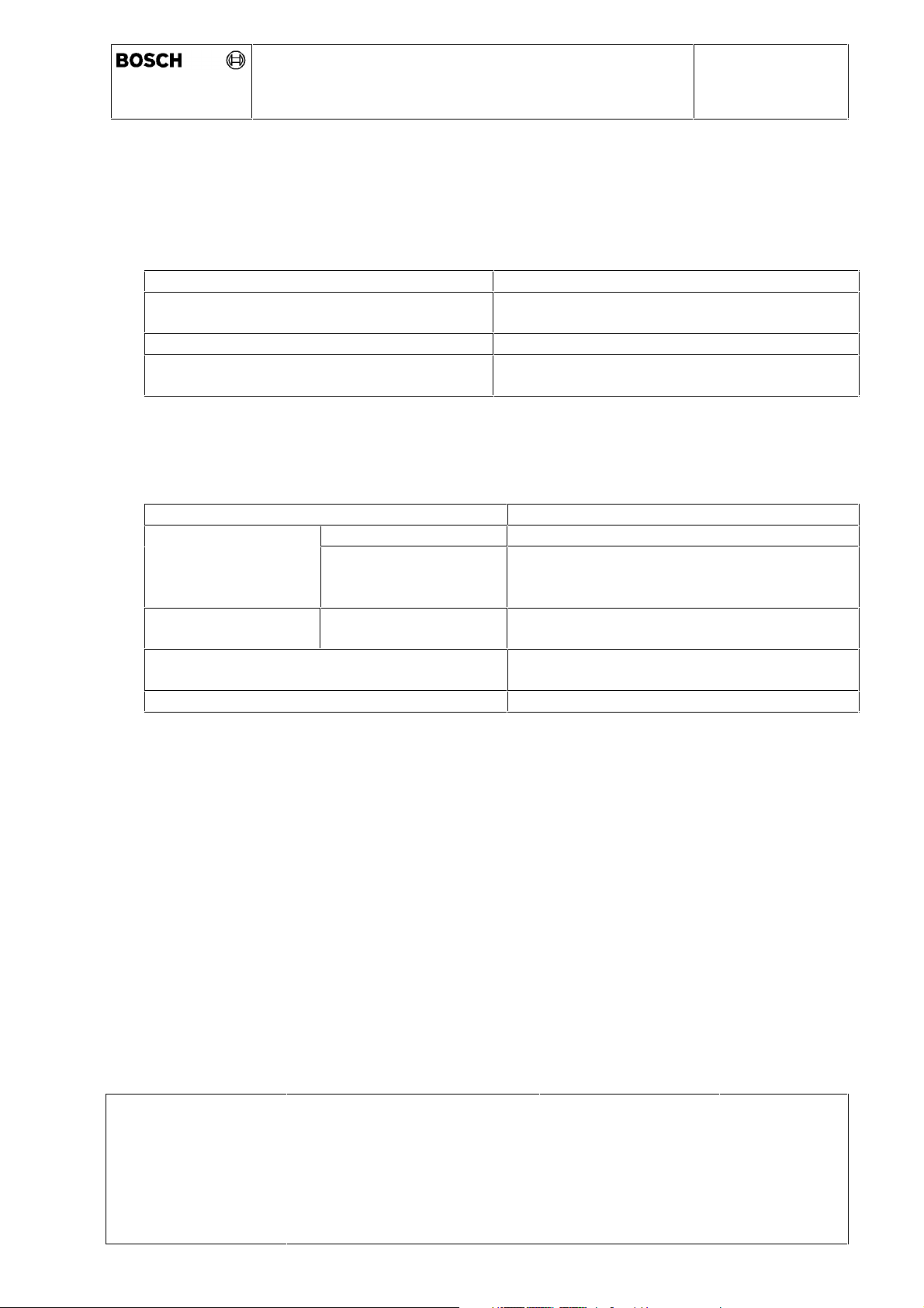
2.1 Temperature range
Storage temperature - 20..+ 50 °C max 5 years
Operating temperature range
(measured at ACC base plate)
Temperature after painting + 125 °C max. 1h, non powered
Temperature range for alignment
(measured at ACC base plate)
2.2 Mechanical and climate conditions
- 40..+ 90 °C
(short time 100°C)
- 10..+ 100 °C
0 265 K60 059
Mounting area Vehicle front area
Kind of protection complete ACC-SCU IP 54 K (DIN 40 050)
frontal area (lens) IP X4 K (DIN 40 050)
IP X6 K (DIN 40 050)
IP X9 K (DIN 40 050)
Stone impact frontal area (lens) Resistance to stone impact acording
VDA 621-427
Vibration Random vibration a
= 27,8 m/s2, 3x8 h
eff
(according ISO/DIS 16750-3)
Weight without bracket < 300g
Issue Date 30.01.03
Print-Date: 13.01.04 Path: \\lrnt11\acc$\Dokumentenablage in Arbeit &
© All rights held by ROBERT BOSCH GMBH, including applic ations for patents and property rights and the right of disposal, suc h as to reproduce or pass on to third parties
Dep.:
offen\Produktspezifikationen.s\TKUs\K60059_8_TKI_ambience conditions ACC2
mechanics.doc
AE-DA/ELR
Name:
Hildebrandt
Page:
6 von 26
Page 7
Technical Customer Information
ACC Distance Control Radar 2nd Generation
0 265 K60 059
Ambience Conditions and Mechanics
3 Mounting conditions
3.1 Installation instructions for the ACC2 - SCU
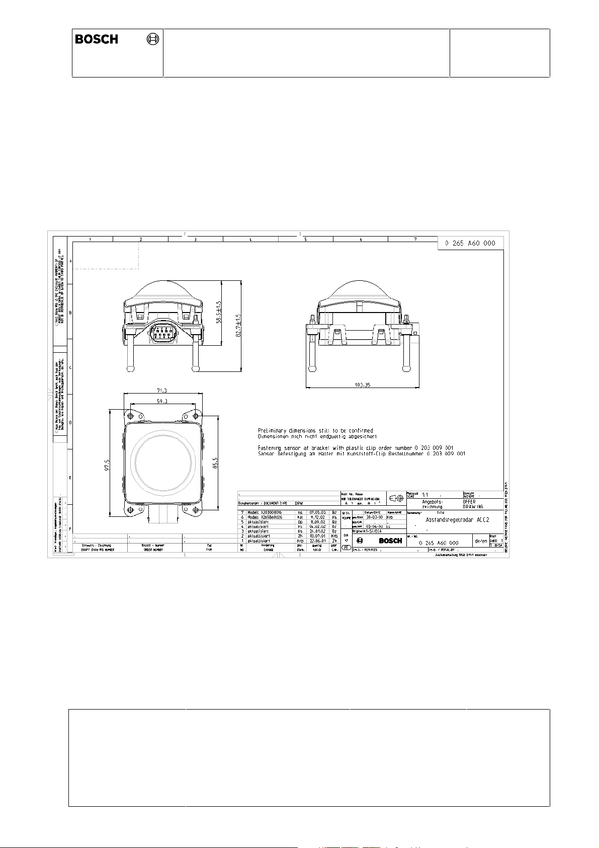
The ACC SCU is installed in the frontal area of the vehicle. The sensor lens points in the
vehicle driving direction, the connector either down to the road or up. The outline
dimensions of the sensor are shown in the following drawing:
Issue Date 30.01.03
Print-Date: 13.01.04 Path: \\lrnt11\acc$\Dokumentenablage in Arbeit &
© All rights held by ROBERT BOSCH GMBH, including applic ations for patents and property rights and the right of disposal, suc h as to reproduce or pass on to third parties
Dep.:
offen\Produktspezifikationen.s\TKUs\K60059_8_TKI_ambience conditions ACC2
mechanics.doc
AE-DA/ELR
Name:
Hildebrandt
Page:
7 von 26
Page 8

Technical Customer Information
ACC Distance Control Radar 2nd Generation
0 265 K60 059
Ambience Conditions and Mechanics
Ideally the sensor is to be integrated into the front-end without a cover in front of its lens.
If the sensor is to be installed behind a cover or a radome, special care must be taken in
selecting the cover-material, cover shape (or design) and position of the cover relatively to
the sensor. Water droplets and snow sticking onto the cover surface might cause
additional attenuation that leads to a restricted performance or availability of ACC. For the
uncovered build-in configuration the lens design of the ACC-SCU is chosen to minimise
these effects. Water droplets can be blown off by the driving wind and sticking snow can
be heated off by the integrated lens heating.
The following table lists the basic demands to the integration of the sensor into a front-end
of the car:
Installation height above ground (roadway)
Horizontal offset relative to the vehicle longitudinal axis
Horizontal angle relative to the vehicle longitudinal axis
Vertical tilt relative to the vehicle longitudinal axis
1
1
1
1
(dependent on pitch when car is fully loaded or while braking)
Clearance of parts (out of metal or even plastic) in front of the
sensor can be described by a cone directly in front of the lens with
the following angles
horizontal
vertical
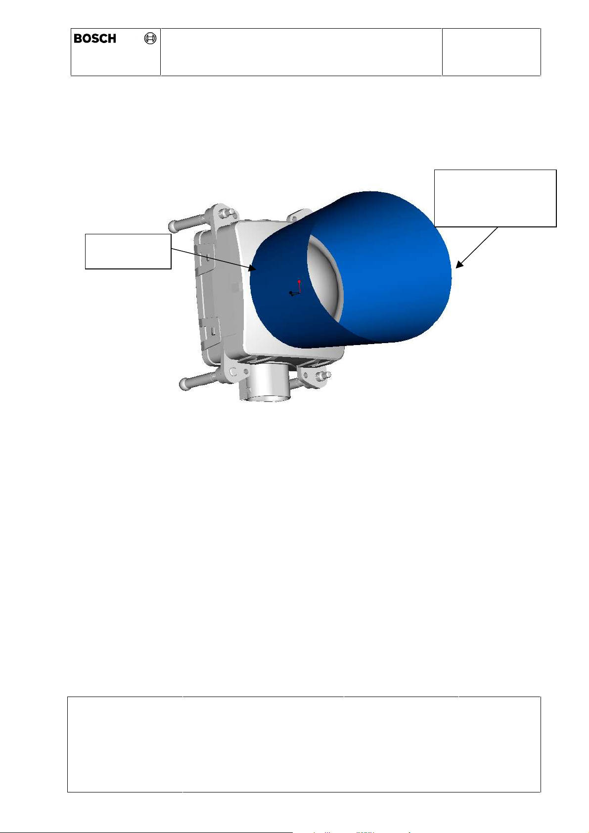
The cone that represents the radar beam in shown in figure 1
Clearance to other vehicle parts:
(sensor-movement during adjustment: ± 3° vertical and horizontal
and additional space for the bracket behind the SCU is considered)
in lateral direction
in front of the lens
behind the sensor (space for clip and bracket)
Permissible attenuation caused by cover (bumper, radome) in front
of the lens ; two-way (radar) loss
The constraints for the cover are:
- homogeneous material has to be favourized
- non perpendicular orientated relatively to sensor radar axis
- favoured materials : see following material list
The material in front of the radar should not degrade the antenna
parameters
• Beamwidth error
• Sidelobe change
• Peak boresight error
In case of radome heating the orientation of wire structures has to
be checked
Wire diameter is limited to max. 0.25mm
min. 300 mm
max. 1000 mm
max. 500 mm
0°
Proposal: adjusting
area at sensor ± 3°
3
± 14°
4
± 7°
2
each side 10 mm
15 mm
30 mm
max . 1 dB
Minimise material
thickness due to
dielectric loss
• max. 1%
• max. 1 dB
• max. 0.1°
linear 45°
from upper left to
lower right as seen in
Issue Date 30.01.03
Print-Date: 13.01.04 Path: \\lrnt11\acc$\Dokumentenablage in Arbeit &
© All rights held by ROBERT BOSCH GMBH, including applic ations for patents and property rights and the right of disposal, suc h as to reproduce or pass on to third parties
Dep.:
offen\Produktspezifikationen.s\TKUs\K60059_8_TKI_ambience conditions ACC2
mechanics.doc
AE-DA/ELR
Name:
Hildebrandt
Page:
8 von 26
Page 9
Technical Customer Information
ACC Distance Control Radar 2nd Generation
0 265 K60 059
Ambience Conditions and Mechanics
driving direction
In case of shaped radome / bumper the radius of the material is
limited
In case of non-homogeneous material the air gap between the
materials is limited
In case of painting carbon based primer is not allowed
1
relative to the ACC SCU; central axis of the lens
2
the full adjustment range is only available at 0° vertical tilt
3
angle results from horizontal beam width (±8°) of the radar beam plus adjustment area
(±3°) plus safety margin (±3°). Car tolerances wont be considered.
4
angle results from vertical beam width (±3°) of the radar beam plus adjustment (±3°)
area plus safety margin (±1°). Car tolerances wont be considered.
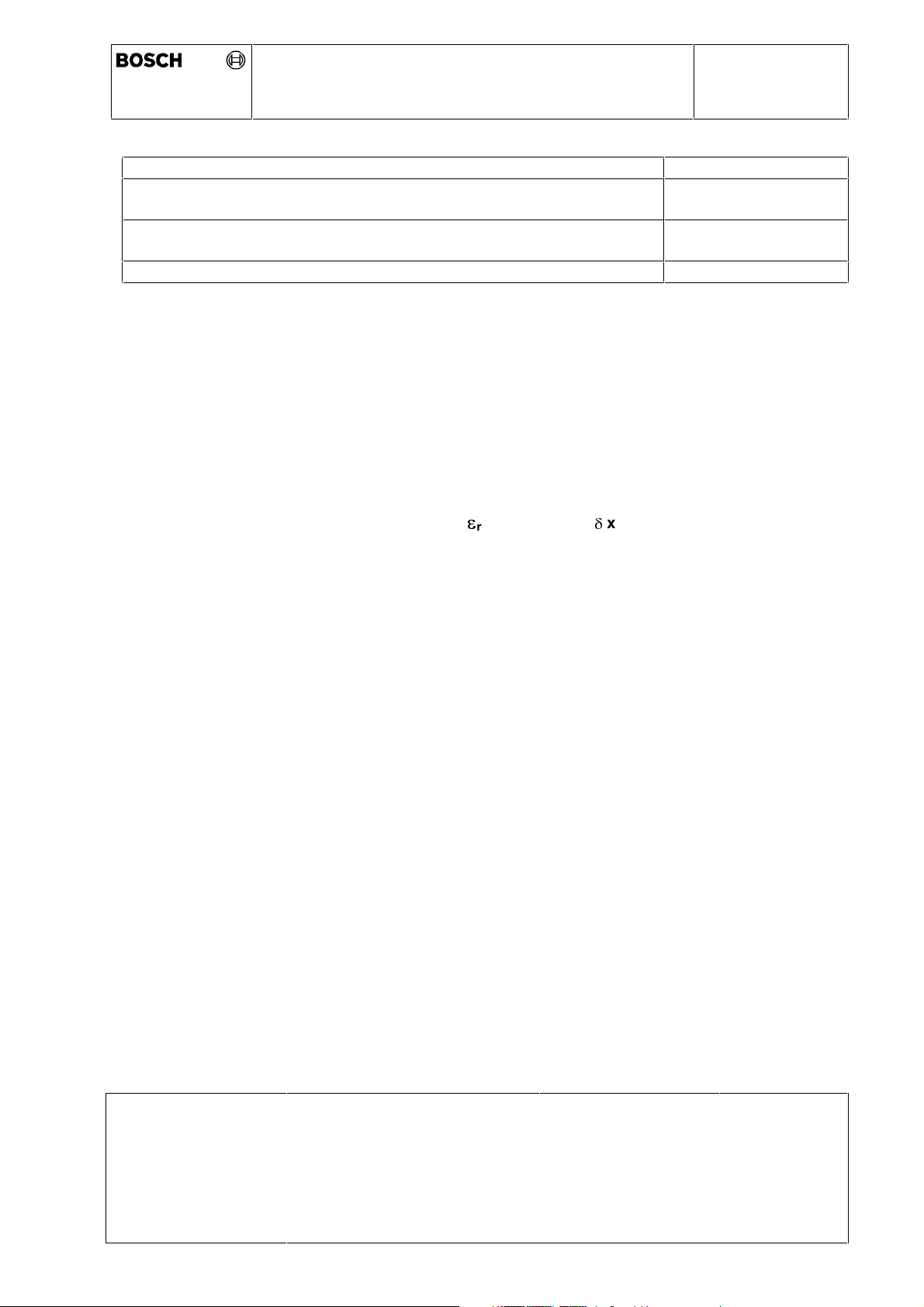
Radome / Bumper Material list:
> 25 mm
< 0.05mm
r
tan x 10
Material
Polyethenimid PEI 3.05 150
Polycarbonat PC 2.7 100
Polyethylene PE 2.3 5
Polypropylene PP 2.18 7
Polytetrafluorethylene PTFE 2.07 5.5
Polymethylenmetacrylat PMMA 2.62 26
-4
Issue Date 30.01.03
Dep.:
AE-DA/ELR
Print-Date: 13.01.04 Path: \\lrnt11\acc$\Dokumentenablage in Arbeit &
offen\Produktspezifikationen.s\TKUs\K60059_8_TKI_ambience conditions ACC2
mechanics.doc
© All rights held by ROBERT BOSCH GMBH, including applic ations for patents and property rights and the right of disposal, suc h as to reproduce or pass on to third parties
Name:
Hildebrandt
Page:
9 von 26
Page 10
Technical Customer Information
ACC Distance Control Radar 2nd Generation
0 265 K60 059
Ambience Conditions and Mechanics
Figure 1: Sketch of the area of clearance directly in front of the sensor (cone for
representing the radar beam)
cone with
elliptical shape:
vertical ±7°
horizontal ±14°
Diameter of
cone: 65 mm
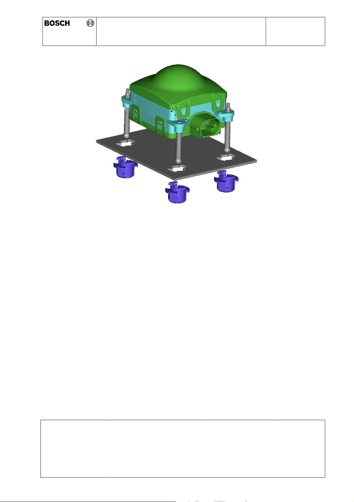
Figure 2: Sketch of the bracket concept for the SCU
Issue Date 30.01.03
Dep.:
AE-DA/ELR
Name:
Hildebrandt
Page:
10 von 26
Print-Date: 13.01.04 Path: \\lrnt11\acc$\Dokumentenablage in Arbeit &
offen\Produktspezifikationen.s\TKUs\K60059_8_TKI_ambience conditions ACC2
mechanics.doc
© All rights held by ROBERT BOSCH GMBH, including applic ations for patents and property rights and the right of disposal, suc h as to reproduce or pass on to third parties
Page 11
ACC Distance Control Radar 2nd Generation
Bracket (metal)
Adjustment
adjustment
Adjustment
screw
for vertical
Technical Customer Information
Ambience Conditions and Mechanics
0 265 K60 059
screw
for horizontal
adjustment
Plastic Clip
Issue Date 30.01.03
Print-Date: 13.01.04 Path: \\lrnt11\acc$\Dokumentenablage in Arbeit &
© All rights held by ROBERT BOSCH GMBH, including applic ations for patents and property rights and the right of disposal, suc h as to reproduce or pass on to third parties
Dep.:
offen\Produktspezifikationen.s\TKUs\K60059_8_TKI_ambience conditions ACC2
mechanics.doc
AE-DA/ELR
Name:
Hildebrandt
Page:
11 von 26
Page 12
Technical Customer Information
ACC Distance Control Radar 2nd Generation
0 265 K60 059
Ambience Conditions and Mechanics
3.2 Sensor bracket / adjustment
The ACC SCU has to be fixed with a vehicle-specific sensor bracket.
The bracket is used to attach the sensor to the vehicle. The points where the bracket is
attached to the vehicle must be selected carefully to ensure a very stable mounting of the
sensor relatively to the vehicle longitudinal axis.
The three clips are used to fix the sensor in the bracket. First each clip is locked by 90°
rotation (clockwise). The sensor is fitted to the bracket by pressing the sensor with guiding
the clip hole (see figure 2 above).
Please note that the bracket needs some space in the near surrounding of the sensor.
The overall dimensions of the sensor with bracket have to be discussed together with the
customer.
Mounting conditions min. 2 fixing points at the vehicle
no relative movement between the fixing points at the
vehicle
long-term stability between the fixing points and relative
to the vehicle longitudinal axis
max torque for clip (locking
in the bracket
)
max pressing force (sensor
to clip holes
min dismantling force
(sensor out of clips)
< 2.5 Nm (max. 3.0 Nm allowed)
< 170 N per screw
> 70 N per screw
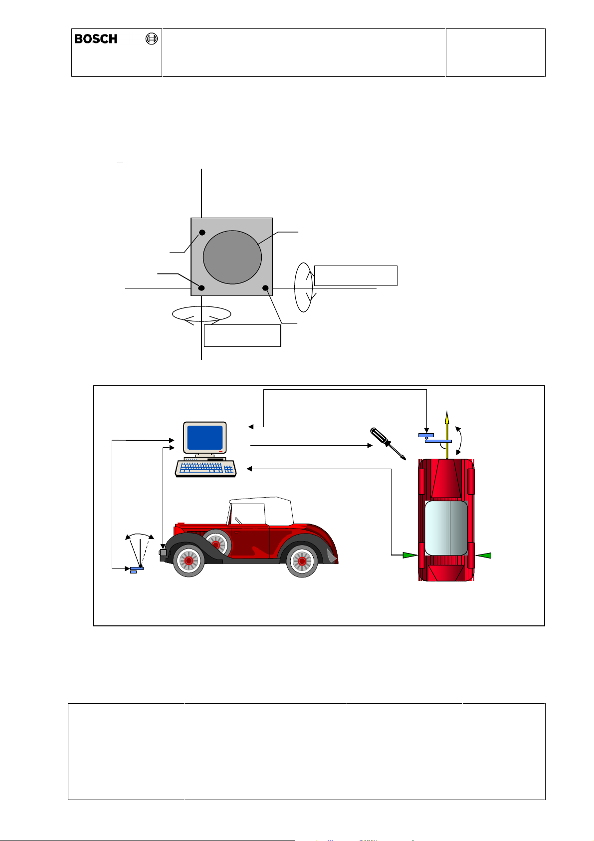
The sensor bracket also enables horizontal and vertical adjustment of the ACC SCU radar
beam to the vehicle longitudinal axis see figure below.
In our solution this is done with self-tapping adjustment screws in plastic mounts.
The adjustment is done after attaching the sensor to the vehicle, using an external
adjustment fixture, like an optical mirror. No external high frequency measurement
equipment is needed.
Adjustment direction for screw driver directly from the front
Adjustment range (proposal)
Horizontal angle
vertical angle
Permissible number of adjustments during
vehicle life
Adjustment accuracy relative to the vehicle
longitudinal axis
1
1
± 3°
± 3°
±
0,2°
±
0,2°
6 adjustment operations per adjustment
screw over the adjustment range
re-determined for each new type of
vehicle
Speed of adjustment screw driver Max. 120 revolutions/min.
Issue Date 30.01.03
Print-Date: 13.01.04 Path: \\lrnt11\acc$\Dokumentenablage in Arbeit &
Dep.:
offen\Produktspezifikationen.s\TKUs\K60059_8_TKI_ambience conditions ACC2
AE-DA/ELR
Name:
Hildebrandt
Page:
12 von 26
mechanics.doc
© All rights held by ROBERT BOSCH GMBH, including applic ations for patents and property rights and the right of disposal, suc h as to reproduce or pass on to third parties
Page 13
Technical Customer Information
ACC Distance Control Radar 2nd Generation
0 265 K60 059
Ambience Conditions and Mechanics
The following sketches illustrate in principle the horizontal and vertical adjustment of the
sensor. The procedure is as easy as the alignment of the head lamps and can be done at
the same test bench in the customers plant.
adjustment screw
for vertical
adjustment
fixed
screw
vert. reflector
plate angle
sensor
data
axis of
azimuth adjustment
alignment
controller
lens
axis of
elevation adjustment
adjustment screw
for horizontal
adjustment
alignment tool
horiz. reflector
plate angle
reflector plate
.
horizontal scan
optional
reflector plate
vertical scan optional
Issue Date 30.01.03
Dep.:
AE-DA/ELR
Print-Date: 13.01.04 Path: \\lrnt11\acc$\Dokumentenablage in Arbeit &
offen\Produktspezifikationen.s\TKUs\K60059_8_TKI_ambience conditions ACC2
mechanics.doc
© All rights held by ROBERT BOSCH GMBH, including applic ations for patents and property rights and the right of disposal, suc h as to reproduce or pass on to third parties
vehicle axes
evaluation
Name:
Hildebrandt
Page:
13 von 26
Page 14
Technical Customer Information
ACC Distance Control Radar 2nd Generation
Ambience Conditions and Mechanics
4 Electrical Data
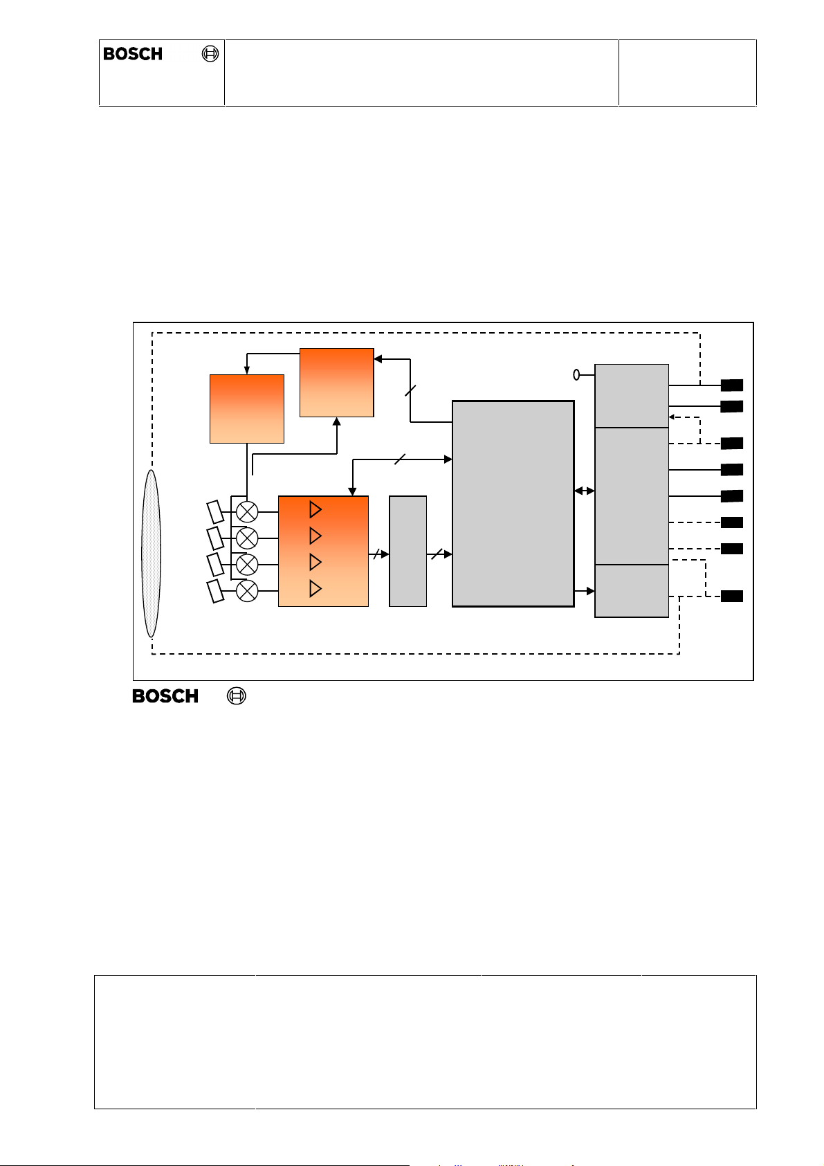
4.1 Block diagram (Top level)
ACC2 (Adaptive Cruise Control)
Top Level Block Diagram ACC2-SCU
0 265 K60 059
Gunn
Oscillator
Gunn
control
V Batt
GND
K-Ltg/WAU
CAN1-H
CAN1-L
CAN2-H
Signal
processing
and
Vstab
Power
supplies
Inter-
face
control
4
16
A/D
Lens-
heating
AE-DA/ELR 20204 0190
CAN2-L
RADOM
/TGAP
© Alle Rechte bei Robert Bosch G mbH, auch für den Fall von Schutzrechtsanmeldungen. Jede Verfügu ngsbefugnis, wie Kopier- und Weitergaberecht, bei uns.
Issue Date 30.01.03
Dep.:
AE-DA/ELR
Print-Date: 13.01.04 Path: \\lrnt11\acc$\Dokumentenablage in Arbeit &
offen\Produktspezifikationen.s\TKUs\K60059_8_TKI_ambience conditions ACC2
mechanics.doc
© All rights held by ROBERT BOSCH GMBH, including applic ations for patents and property rights and the right of disposal, suc h as to reproduce or pass on to third parties
Name:
Hildebrandt
Page:
14 von 26
Page 15
Technical Customer Information
ACC Distance Control Radar 2nd Generation
GND
CAN2-L
CAN1-H
VBatt (Kl30)
K-Ltg/ WAU
CAN1-L
CAN2-H
RADOM / TGAP
0 265 K60 059
Ambience Conditions and Mechanics
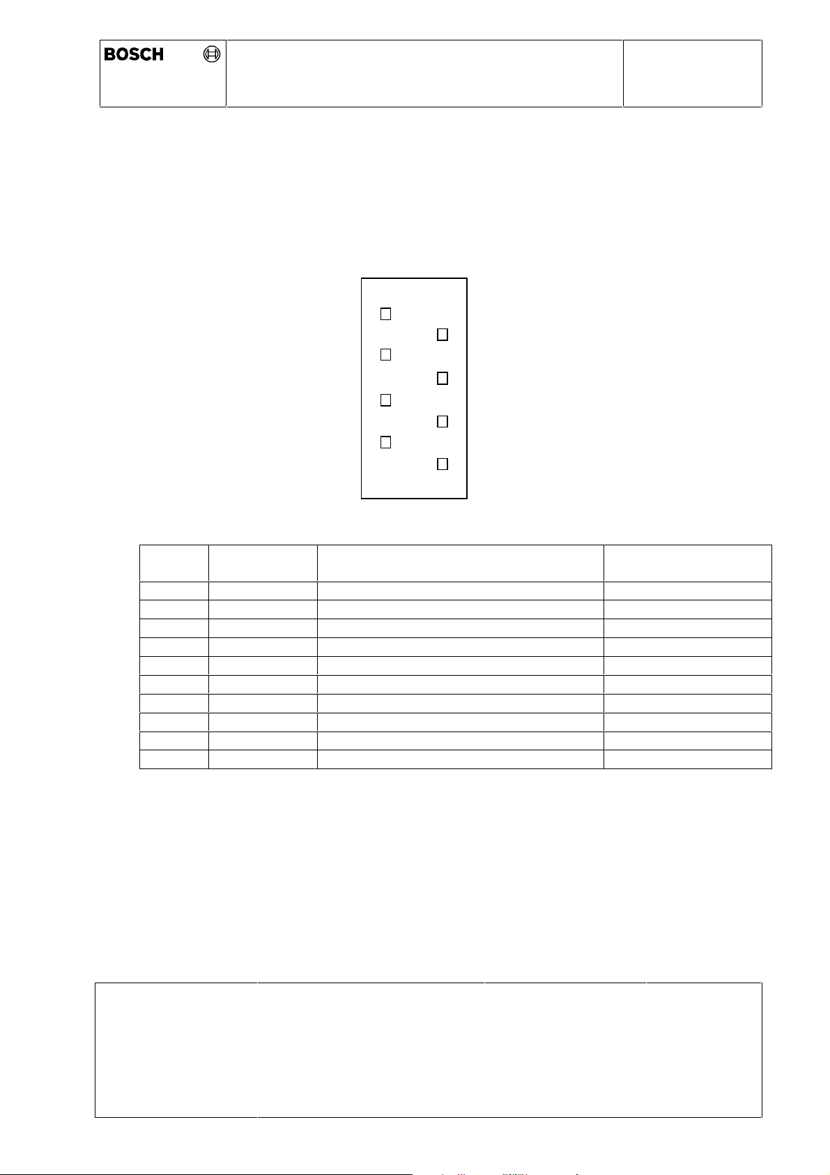
4.2 Pinning and Type of Connector
The following sketch shows the pinning of the ACC sensor. The number of pins are fixed
to eight.
1
5
2
6
3
7
4
8
Pin-No. Designation Description Proposed wire size for
connecting harness
1 GND Sensor ground: connected to pin 31 0,75 mm
2 CAN1-H CAN1 High 0,5 mm
3 CAN1-L CAN1 Low 0,5 mm
4 K-Ltg
4 WAU
1)
1)
Diagnosis interface 0,5 mm
Wake up signal 0,5 mm
5 CAN2-H CAN2 High 0,5 mm
6 CAN2-L CAN2 Low 0,5 mm
7 Radome
7 TGAP
2)
2)
Output voltage for Radome heating 0,75 mm
Analogue signal input (time gap) 0,5 mm
8 V Batt Supply voltage for sensor 0,75 mm
1)
: Either K-line or WAU possible
2)
: Either Radome or TGAP possible
2
2
2
2
2
2
2
2
2
2
The 2nd CAN bus can be used as a private CAN for future ACC functions.
The plug itself is designed according the MQS System from AMP.
- The SCU plug is: AMP No.: C-114-19063-34 Kod A
- The harness wiring plug is: AMP No.: 153 42 29 (MQS System)
Issue Date 30.01.03
Dep.:
AE-DA/ELR
Print-Date: 13.01.04 Path: \\lrnt11\acc$\Dokumentenablage in Arbeit &
offen\Produktspezifikationen.s\TKUs\K60059_8_TKI_ambience conditions ACC2
mechanics.doc
© All rights held by ROBERT BOSCH GMBH, including applic ations for patents and property rights and the right of disposal, suc h as to reproduce or pass on to third parties
Name:
Hildebrandt
Page:
15 von 26
Page 16
Technical Customer Information
ACC Distance Control Radar 2nd Generation
Ambience Conditions and Mechanics
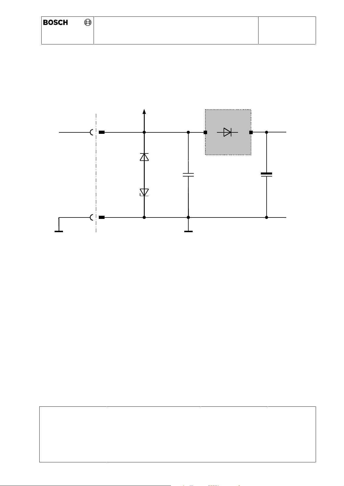
4.3 V Bat - Interface
The equivalent circuit diagram of the V Bat - interface is as follows:
Lens heating
Intelligent
ASIC
VBat
D1
C1 C2
0 265 K60 059
+
D2
GND
SCU
Electrical specification:
U
= 12 V (full operation from 10V to 16V)
nom
I
≤ 1.5 A (without lens heating)
max
I
≤
3.0 A (with lens heating at ambient temperature < 10°C)
max
V bat shall be fused externally by min. 10 A
V bat shall be protected externally against over voltage and load dump up to 40 V
Quiescent Current:
Sleep Mode: I
(wake up not activated) I
Load capacitor: C1 + C2 < 300µF
≤ 50µA (without lens heating)
max
≤ 100µA (with lens heating)
max
Issue Date 30.01.03
Dep.:
AE-DA/ELR
Print-Date: 13.01.04 Path: \\lrnt11\acc$\Dokumentenablage in Arbeit &
offen\Produktspezifikationen.s\TKUs\K60059_8_TKI_ambience conditions ACC2
mechanics.doc
© All rights held by ROBERT BOSCH GMBH, including applic ations for patents and property rights and the right of disposal, suc h as to reproduce or pass on to third parties
Name:
Hildebrandt
Page:
16 von 26
Page 17
Technical Customer Information
ACC Distance Control Radar 2nd Generation
Ambience Conditions and Mechanics
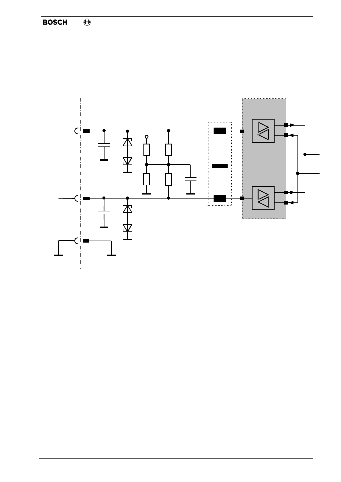
4.4 CAN - Interfaces
The equivalent circuit diagram of the CAN - interface is as follows:
CANH
+5V
0 265 K60 059
Intelligent
ASIC
C1
D1
(opt.)
R2
R3R1
R4
C3
CANL
C2
D2
(opt.)
GND
SCU
Optional population:
C1, C2 ≤ 100pF
C3< 10nF
R1,R2 < 1,5KΩ; R3, R4 = 61,9 bzw. 66,4 Ω
L: Choke 2 x 11µH (TDK, EPCOS)
D: Dual Common Cathode Zener for ESD Protection
L1
S:\ELR2\ACC2\Schnittstellenblätter für TKU\C AN.doc
The circuitry shows all possible options on the CAN.-interface.
If termination of the bus is not required the two 62 Ω-resistors(R
or changed to higher value f.e. 1,3KΩ. The choke might be omitted if not required for
EMC-reason.
The CAN bus is specified in „CAN Specification of the CAN physical layer for High-SpeedApplication up to 1Mbit/s“, dated October 1989.
Issue Date 30.01.03
Print-Date: 13.01.04 Path: \\lrnt11\acc$\Dokumentenablage in Arbeit &
© All rights held by ROBERT BOSCH GMBH, including applic ations for patents and property rights and the right of disposal, suc h as to reproduce or pass on to third parties
Dep.:
offen\Produktspezifikationen.s\TKUs\K60059_8_TKI_ambience conditions ACC2
mechanics.doc
AE-DA/ELR
Name:
and R4) can be omitted
3
Hildebrandt
Page:
17 von 26
Page 18

Technical Customer Information
ACC Distance Control Radar 2nd Generation
Ambience Conditions and Mechanics
0 265 K60 059
Issue Date 30.01.03
Print-Date: 13.01.04 Path: \\lrnt11\acc$\Dokumentenablage in Arbeit &
© All rights held by ROBERT BOSCH GMBH, including applic ations for patents and property rights and the right of disposal, suc h as to reproduce or pass on to third parties
Dep.:
offen\Produktspezifikationen.s\TKUs\K60059_8_TKI_ambience conditions ACC2
mechanics.doc
AE-DA/ELR
Name:
Hildebrandt
Page:
18 von 26
Page 19
Technical Customer Information
ACC Distance Control Radar 2nd Generation
0 265 K60 059
Ambience Conditions and Mechanics
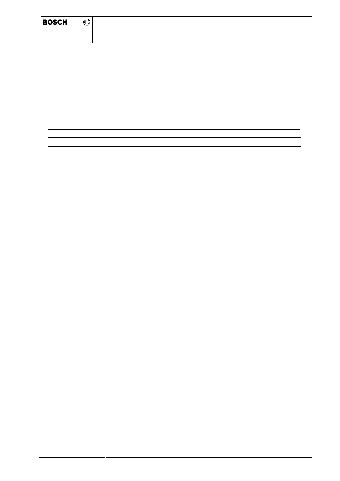
The following typical details are taken from this specification.
These details are valid for an ECU which is separated from the bus and loaded with a 60Ω
resistor:
Recessive state: (corresponding to logical 0)
Output voltage:
Input range:
Input resistor:
Dominant state: (corresponding to logical 1)
Output voltage:
Input range:
-0,5 V ≤ U
-1,0 V ≤ U
1,5 V ≤ U
0,9 V ≤ U
Signal1/Signal2
Signal1/Signal2
> 9 kΩ
Signal1/Signal2
Signal1/Signal2
≤ 0,05 V
≤ 0,5 V
≤ 3,0 V
≤ 5,0 V
Issue Date 30.01.03
Print-Date: 13.01.04 Path: \\lrnt11\acc$\Dokumentenablage in Arbeit &
© All rights held by ROBERT BOSCH GMBH, including applic ations for patents and property rights and the right of disposal, suc h as to reproduce or pass on to third parties
Dep.:
offen\Produktspezifikationen.s\TKUs\K60059_8_TKI_ambience conditions ACC2
mechanics.doc
AE-DA/ELR
Name:
Hildebrandt
Page:
19 von 26
Page 20
Technical Customer Information
ACC Distance Control Radar 2nd Generation
Ambience Conditions and Mechanics
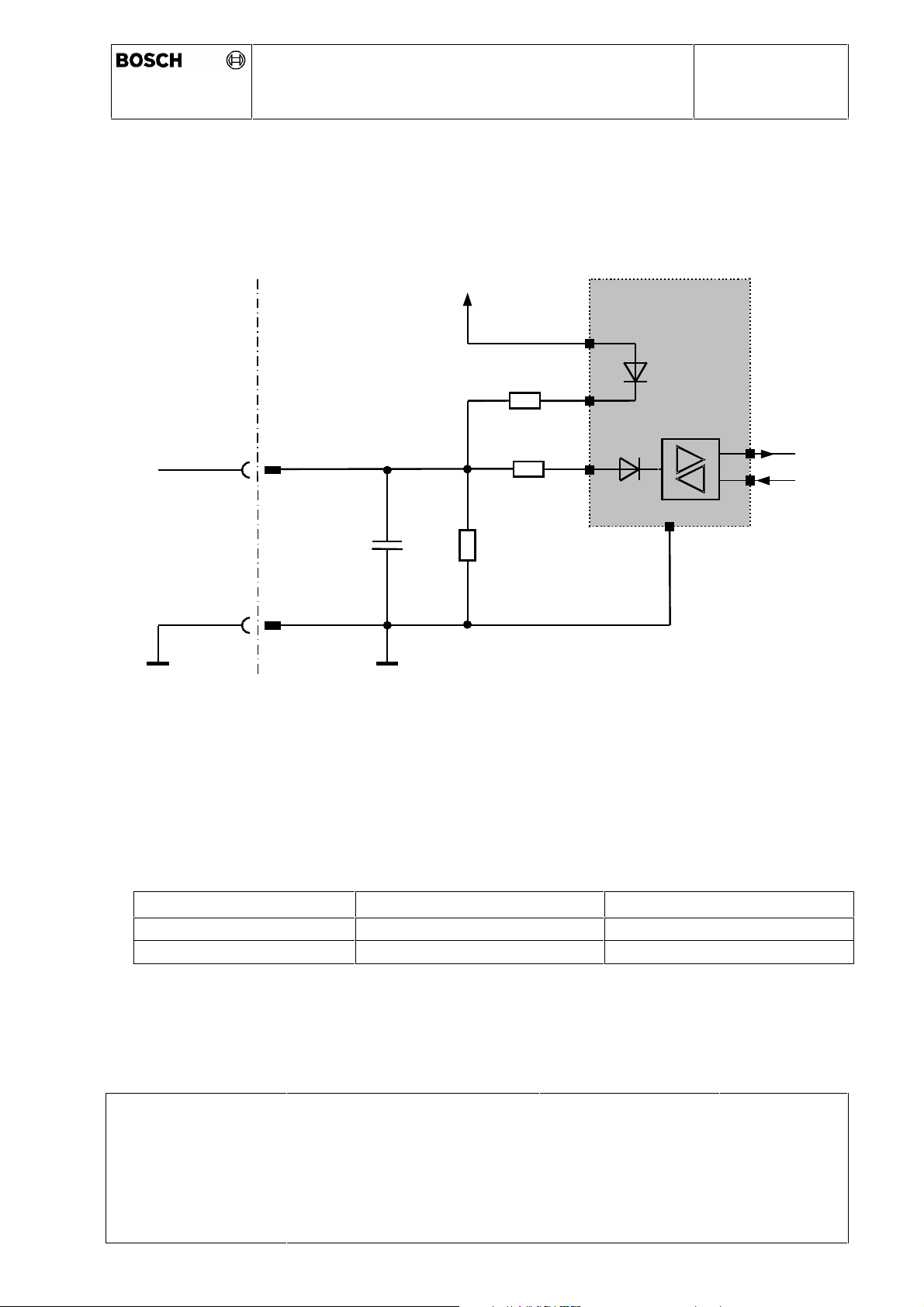
4.5 Optional Diagnosis Interface (K-Line)
The equivalent circuit diagram of the diagnosis interface is as follows:
0 265 K60 059
K-Ltg
GND
SCU
VBatt
Intelligent
ASIC
R1
R2
R3
C1
Electrical specification:
R1 ≤ 110 kΩ
R3 ≤ TBC
Either R1 or R3 to be inserted
R2 ≤ 80 Ω
C1 ≤ 500 pF
Transmit Receive
logical „1“
logical „0“
Issue Date 30.01.03
Print-Date: 13.01.04 Path: \\lrnt11\acc$\Dokumentenablage in Arbeit &
Dep.:
AE-DA/ELR
≥ 0.8 × V Bat ≥ 0.7 × V Bat
≤ 0.2 × V Bat ≤ 0.3 × V Bat
Name:
Hildebrandt
Page:
20 von 26
offen\Produktspezifikationen.s\TKUs\K60059_8_TKI_ambience conditions ACC2
mechanics.doc
© All rights held by ROBERT BOSCH GMBH, including applic ations for patents and property rights and the right of disposal, suc h as to reproduce or pass on to third parties
Page 21
Technical Customer Information
ACC Distance Control Radar 2nd Generation
Ω
Ambience Conditions and Mechanics
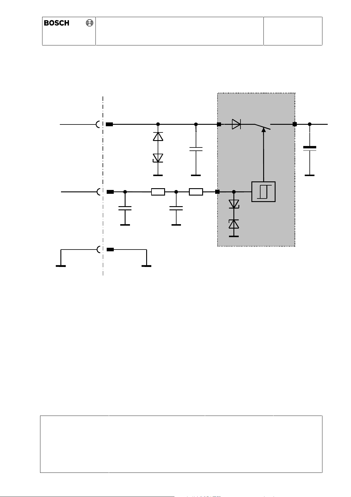
4.6 Optional Wake Up Line (WAU)
The equivalent circuit diagram of the wake-up interface is as follows:
VBatt
0 265 K60 059
Intelligent
ASIC
Wake-up voltages:
WAU
GND
SCU
D1
D2
10K
C4
+
C1
Ω
C3C2
10K
R:\ELR2\ACC2\Schnittstellenblätter für TKU\WAU.doc
U
U
WAU-On
WAU-Off
≥ 4.0 V
≤ 2.0 V
C2 + C3 ≤ 200 nF
Issue Date 30.01.03
Print-Date: 13.01.04 Path: \\lrnt11\acc$\Dokumentenablage in Arbeit &
© All rights held by ROBERT BOSCH GMBH, including applic ations for patents and property rights and the right of disposal, suc h as to reproduce or pass on to third parties
Dep.:
offen\Produktspezifikationen.s\TKUs\K60059_8_TKI_ambience conditions ACC2
mechanics.doc
AE-DA/ELR
Name:
Hildebrandt
Page:
21 von 26
Page 22
Technical Customer Information
ACC Distance Control Radar 2nd Generation
Intelligent
Ambience Conditions and Mechanics
4.7
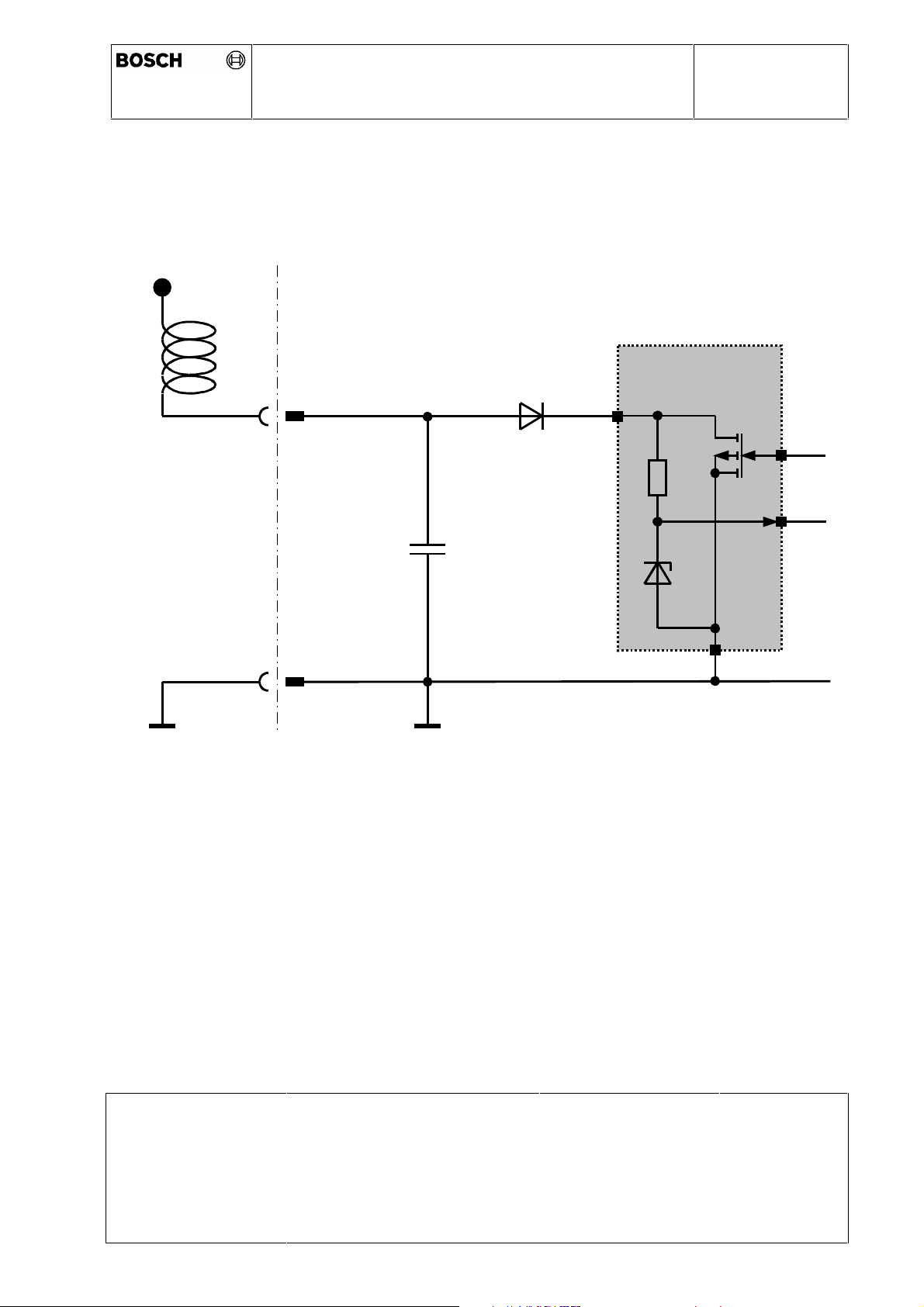
Optional Radome Heating Line (RADOM)
The equivalent circuit diagram of the RADOM - interface is as follows:
VBatt
0 265 K60 059
Electrical specification:
U
= 12 V
nom
I
≤ 3 A at U
max
nom
RADOM
GND
SCU
C1
D1
ASIC
Quiescent current:
Sleep mode: I
(wake up not activated) I
Active mode: I
max
max
(wake up activated)
Load capacitor: C
Issue Date 30.01.03
Print-Date: 13.01.04 Path: \\lrnt11\acc$\Dokumentenablage in Arbeit &
© All rights held by ROBERT BOSCH GMBH, including applic ations for patents and property rights and the right of disposal, suc h as to reproduce or pass on to third parties
≤ 22 nF
1
Dep.:
offen\Produktspezifikationen.s\TKUs\K60059_8_TKI_ambience conditions ACC2
mechanics.doc
AE-DA/ELR
≤ 10µA (T<25°C)
max
≤ 50µA (T<125°C)
≤ 200µA
Name:
Hildebrandt
Page:
22 von 26
Page 23
Technical Customer Information
ACC Distance Control Radar 2nd Generation
VBatt
Ambience Conditions and Mechanics
4.8
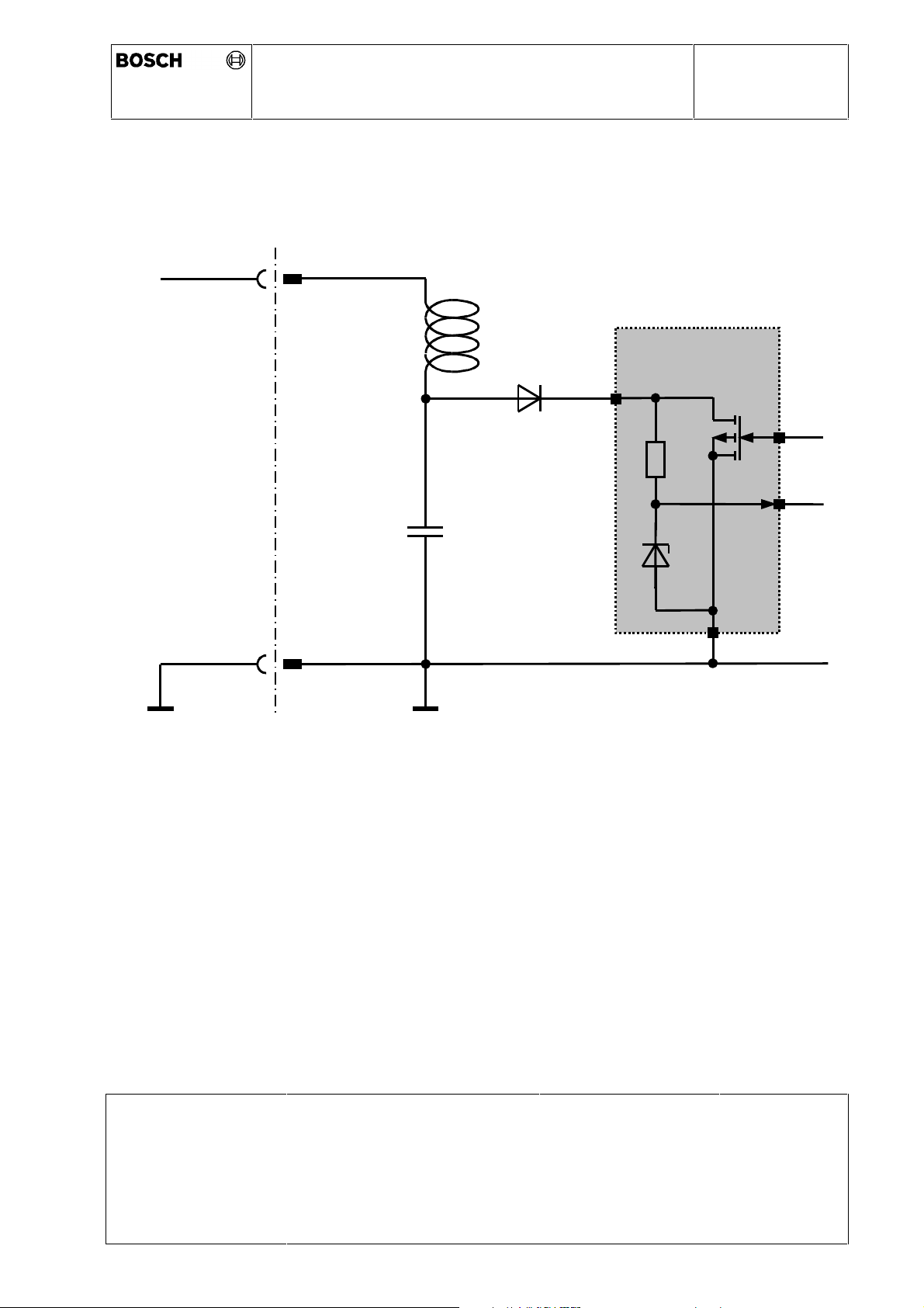
Optional Lens Heating Line
The equivalent circuit diagram of the lens heating is as follows:
D1
0 265 K60 059
Intelligent
ASIC
C1
GND
SCU
Electrical specification:
U
= 12 V
nom
I
≤ 1.2 A at U
typ
I
≤ 1.5 A at U
max
Quiescent current:
Sleep mode: Imax ≤ 10µA (T<25°C)
(wake up not activated) Imax ≤ 50µA (T<125°C)
Active mode: Imax ≤ 200µA
(wake up activated)
nom
nom
Load capacitor: C
Issue Date 30.01.03
Print-Date: 13.01.04 Path: \\lrnt11\acc$\Dokumentenablage in Arbeit &
© All rights held by ROBERT BOSCH GMBH, including applic ations for patents and property rights and the right of disposal, suc h as to reproduce or pass on to third parties
≤ 22 nF
1
Dep.:
offen\Produktspezifikationen.s\TKUs\K60059_8_TKI_ambience conditions ACC2
mechanics.doc
AE-DA/ELR
Name:
Hildebrandt
Page:
23 von 26
Page 24

Technical Customer Information
ACC Distance Control Radar 2nd Generation
Ambience Conditions and Mechanics
0 265 K60 059
Issue Date 30.01.03
Print-Date: 13.01.04 Path: \\lrnt11\acc$\Dokumentenablage in Arbeit &
© All rights held by ROBERT BOSCH GMBH, including applic ations for patents and property rights and the right of disposal, suc h as to reproduce or pass on to third parties
Dep.:
offen\Produktspezifikationen.s\TKUs\K60059_8_TKI_ambience conditions ACC2
mechanics.doc
AE-DA/ELR
Name:
Hildebrandt
Page:
24 von 26
Page 25
Technical Customer Information
ACC Distance Control Radar 2nd Generation
Ambience Conditions and Mechanics
4.9
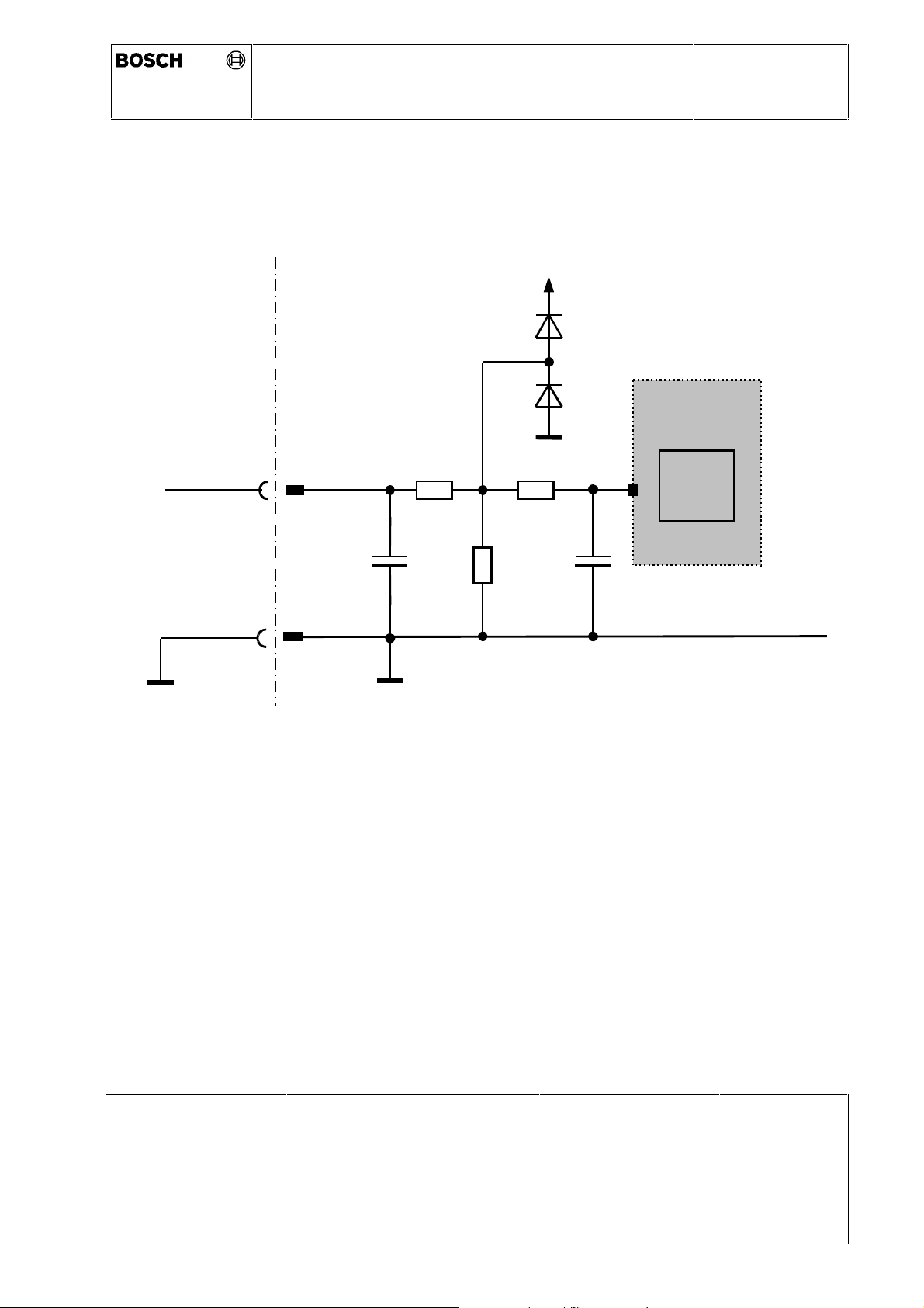
Optional Time Gap Input (TGAP)
The equivalent circuit diagram of the TGAP - interface is as follows:
3,35V
D1
0 265 K60 059
ZTL
R1
D2
R3
µController
A/D
C1
GND
SCU
Logic levels to be discussed and defined between the customer and Bosch.
R2
C2
S:\ELR2\ACC2\Schnittstellenblätter für TKU\Timegap.doc
Issue Date 30.01.03
Print-Date: 13.01.04 Path: \\lrnt11\acc$\Dokumentenablage in Arbeit &
© All rights held by ROBERT BOSCH GMBH, including applic ations for patents and property rights and the right of disposal, suc h as to reproduce or pass on to third parties
Dep.:
offen\Produktspezifikationen.s\TKUs\K60059_8_TKI_ambience conditions ACC2
mechanics.doc
AE-DA/ELR
Name:
Hildebrandt
Page:
25 von 26
Page 26

Technical Customer Information
ACC Distance Control Radar 2nd Generation
0 265 K60 059
Ambience Conditions and Mechanics
5 Environmental tests
The tests described below will be carried out with the complete ACC-SCU including the
76,5 GHz transceiver-module, the connected wiring harness plug and the mounted
sensor bracket (according to the offer drawing). The “bracket only” tests will be carried
out with an ACC-SCU- weight dummy, these tests are always passive tests.
Qualification tests are intended to anticipate artificial ageing to simulate long term
behaviour of the devices under test. Unless otherwise stated, the tolerances in the
temperatures are ± 2 °C and all laboratory tests are performed under the following
conditions:
• upper temperature (T
• lower temperature (T
) + 85 °C ± 2 °C
max
) - 40 °C ± 2 °C
min
• room temperature + 23 °C ± 5 °C.
• relative humidity 45 to 75 %
• test power 14 V ± 0,2 V
• operation mode active / non powered (valid for ACC-SCU)
Test criteria:
• Electrical function test completed without failures (if test values outside the tolerance,
a separate evaluation is necessary).
• No electrical or mechanical error function during the tests.
• No functionally related mechanical damages after the tests and no functionally related
foreign substances in the device under test after the kind-of-protection-tests.
After the tests the devices will be scraped not earlier than 1 year and not last than 2
years after SOP.
Issue Date 30.01.03
Print-Date: 13.01.04 Path: \\lrnt11\acc$\Dokumentenablage in Arbeit &
© All rights held by ROBERT BOSCH GMBH, including applic ations for patents and property rights and the right of disposal, suc h as to reproduce or pass on to third parties
Dep.:
offen\Produktspezifikationen.s\TKUs\K60059_8_TKI_ambience conditions ACC2
mechanics.doc
AE-DA/ELR
Name:
Hildebrandt
Page:
26 von 26
Page 27
Technical Customer Information
ACC Distance Control Radar 2nd Generation
0 265 K60 059
Ambience Conditions and Mechanics
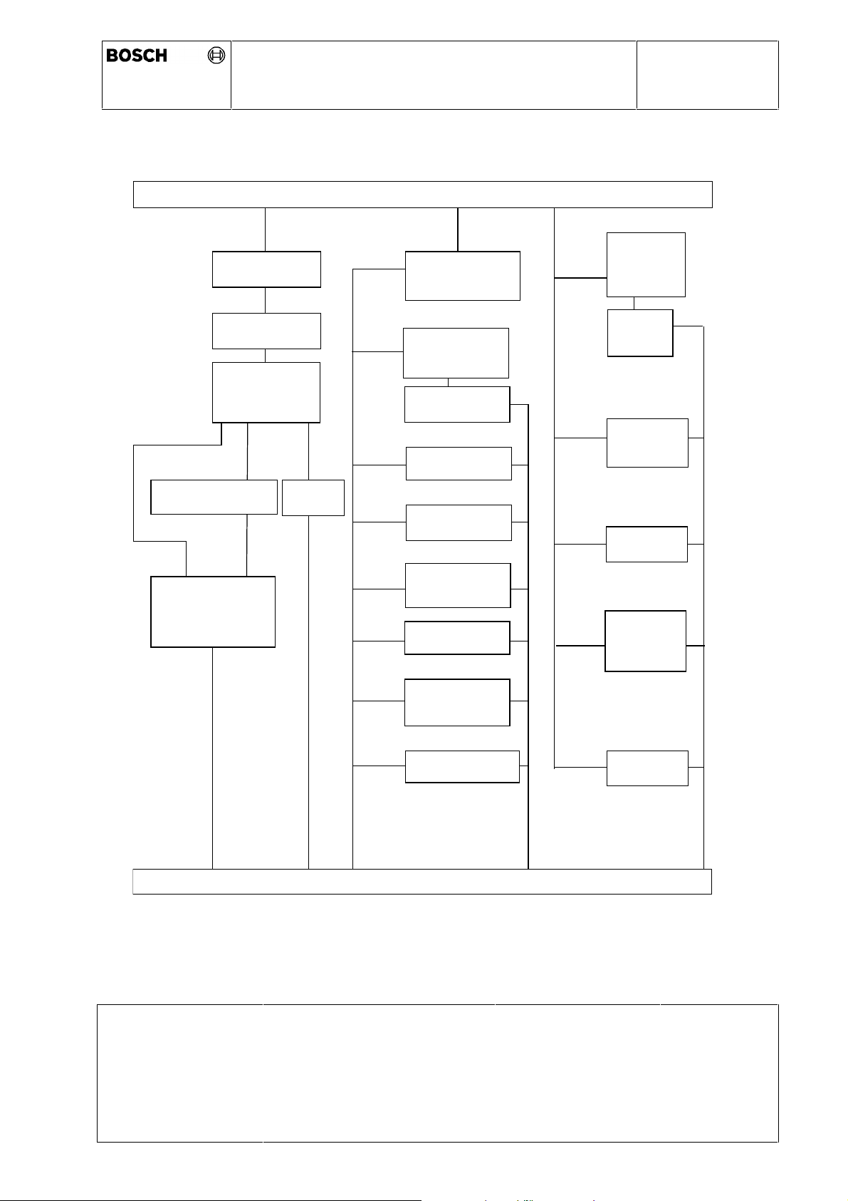
The ACC2 sensor with its bracket will be approved according the following test sequence:
Initial electrical and visual test
11 DUT
High temp.
High temp. storage
Thermal cycle (artificial ageing)
5 DUT
endurance
test
Low temp. storage
Thermal cycle
(artificial ageing) /
Thermal schock
(pssive)
2 DUT
Random vibration test
Water protection
IP X4K
IP X6K
IP X9K
8 DUT 1 DUT
Shock test
1 DUT
1 DUT
1 DUT
1 DUT
1 DUT
1 DUT
Dust protection
IP 6x K
Damp heat, cyclic
Dip test
Salt mist
Comb. Salt/
humidity
Industrial climate
Condensation
products
5 DUT
3 DUT
1 DUT
Stepped
temp. Test
Temp. cycles
(praxis)
Drop test
Resistance
against painting
19 DUT
Final electrical and visual test
Chemical resistance
1 DUT
Stoning test
Customer specific tests in addition to this test sequence have to be discussed and fixed in
detail together with Bosch and might be charged separately.
Issue Date 30.01.03
Dep.:
Print-Date: 13.01.04 Path: \\lrnt11\acc$\Dokumentenablage in Arbeit &
offen\Produktspezifikationen.s\TKUs\K60059_8_TKI_ambience conditions ACC2
mechanics.doc
© All rights held by ROBERT BOSCH GMBH, including applic ations for patents and property rights and the right of disposal, suc h as to reproduce or pass on to third parties
AE-DA/ELR
Name:
Hildebrandt
Page:
27 von 26
Page 28

Technical Customer Information
ACC Distance Control Radar 2nd Generation
0 265 K60 059
Ambience Conditions and Mechanics
6 EMC
6.1 Vehicle Tests
This EMC tests plan describes the general requirements to electronic equipment in the
car. Additional tests or changed parameters may be necessary because of specific SCU
requirements. The electronic design of the device, the location and wiring of the SCU in
the car may cause the necessity of additional tests.
All tests are to be carried out within an certified EMC test laboratory at an air humidity
between 45% ± 15% and a room temperature of 23°C ± 5°C unless otherwise stated.
In general vehicle tests are in customer’s responsibility. Test vehicles, which are identical
to production vehicles, become available only at a very late date, so we must refer to the
bench tests described below for internal release of the project. Nevertheless it is
necessary to test the performance of the system in the vehicle.
If the SCU passes the bench tests, but fails the vehicle tests, then further investigations
are necessary. To find an acceptable solution the responsible sensor development
department will work together with the customer. The final release can only be made in a
vehicle test.
The ACC2 sensor will be approved according the following EMC test sequence:
• Radiation Immunity according ISO 11541-2 (12.1995)
• Radiated Emission according CISPR 25 Section 2 (11.1995)
• Disturbance by other in-vehicle components
Further customer specific tests in addition to this test sequence have to be discussed and
fixed in detail together with Bosch and might be charged separately.
Issue Date 30.01.03
Print-Date: 13.01.04 Path: \\lrnt11\acc$\Dokumentenablage in Arbeit &
© All rights held by ROBERT BOSCH GMBH, including applic ations for patents and property rights and the right of disposal, suc h as to reproduce or pass on to third parties
Dep.:
offen\Produktspezifikationen.s\TKUs\K60059_8_TKI_ambience conditions ACC2
mechanics.doc
AE-DA/ELR
Name:
Hildebrandt
Page:
28 von 26
Page 29

Technical Customer Information
ACC Distance Control Radar 2nd Generation
Ambience Conditions and Mechanics
6.2 Bench Tests
The bench test plan for the ACC SCU is defined as follows:
• Conducted Immunity
ESD according ISO TR 10605 (10.1994) and IEC 801-2 (04.1991)
electrical transient conduction along supply lines according ISO 7637-1 (06.1990)
electrical transient transmission by capacitive and inductive coupling according
ISO 7637-3 (07.1995)
immunity to abnormal supply voltage
over-voltage
sinusoidal ripple
micro cut off (drop outs)
supply voltage ramps
short circuit to supply voltage
• Conducted Emission
transient emission test according ISO 7637-1 (06.1990), CISPR 25 chapter 3
clause 11.2.1 (11.1995)
• Radiation Immunity
strip line test according ISO 11452-5 (12.1995)
BCI test method according ISO 11452-4 (12.1995)
absorber lined chamber according ISO 11452-2 (12.1995)
mobile phone simulation test according ISO 1145-2 (12.1995)
• Radiation Emission
antenna measurement according CISPR 25 chapter 13
Strip line test according ISO 11452-5
0 265 K60 059
Further customer specific tests in addition to this test sequence have to be discussed and
fixed in detail together with Bosch and might be charged separately.
Issue Date 30.01.03
Print-Date: 13.01.04 Path: \\lrnt11\acc$\Dokumentenablage in Arbeit &
Dep.:
offen\Produktspezifikationen.s\TKUs\K60059_8_TKI_ambience conditions ACC2
AE-DA/ELR
Name:
Hildebrandt
Page:
29 von 26
mechanics.doc
© All rights held by ROBERT BOSCH GMBH, including applic ations for patents and property rights and the right of disposal, suc h as to reproduce or pass on to third parties
 Loading...