

Technical Customer Documentation
Document version:
Refer to the Change history
CC-DA/ECR5
FR5CPEC
0265K60532
Page:
1
Product identification Product name
FR5CPEC
Type designation
Generation 5 Front Plus
Series parts number
0203301249
Number of the offer drawing
Name of customer
Number, issue/version, date, and title of
the customer specification
Version and date of the TCD
Version 1.0 (initial) – 18.05.2018
Issued by
Mueller
Internal Bosch Baseline ID
Version 25.0 from 16.05.2018
Date
changed on
Document
Version
Description of change
Name, Department
09.10.2018
1.0
First version - not released Extract for Type Approval of FR5CPEC
Andreas Mueller
CC-DA/ECR5
Change history
© All rights reserved, Robert Bosch GmbH, also for the case of protected rights applications every power of disposal, like copy-right
and passing on rights, with us. The valid issue of this template is filed in CC-DA process landscape.

Technical Customer Documentation
Document version:
Refer to the Change history
CC-DA/ECR5
FR5CPEC
0265K60532
Page:
2
1. General product description ................................................................................................... 3
1.1. Main functions and properties of the product .................................................................. 3
1.1.1. Principle ................................................................................................................... 3
1.1.2. Block diagram .......................................................................................................... 4
1.1.3. Preliminary Assembly concept ................................................................................. 5
1.2. Labeling of the product ................................................................................................... 6
1.2.1. Radio Frequency Homologation .............................................................................. 6
1.2.1.1. Phrases and Markings ...................................................................................... 6
1.3. Dimensions and weights ................................................................................................. 9
1.4. Power consumption / power output ............................................................................... 10
1.5. General remarks for service, repair and maintenance .................................................. 10
1.6. Information on disposal and recycling ........................................................................... 10
2. System description ............................................................................................................... 11
2.1. Vehicle integration interfaces ........................................................................................ 11
2.1.1.1. Radar Cone .................................................................................................... 11
2.1.1.2. Fascia design guidelines ................................................................................ 13
2.1.1.3. Installation Hints ............................................................................................. 15
3. Technical data with measured variables and measuring conditions .................................... 19
3.1. Mechanical characteristics ............................................................................................ 19
3.2. Electrical characteristics ............................................................................................... 20
3.2.1. Electrical Vehicle Connector Pinning ..................................................................... 21
3.2.1.1. Pin Properties ................................................................................................. 21
3.2.1.2. Pin Assignment ............................................................................................... 21
3.2.2. Vehicle Power Supply ............................................................................................ 22
3.2.2.1. Constraints and Definitions ............................................................................. 22
3.2.2.2. Power Supply System 12V ............................................................................. 22
3.2.3. Electrical Communication Interface ....................................................................... 24
3.2.3.1. CAN1 Interface ............................................................................................... 24
3.2.3.2. Ethernet Interface ........................................................................................... 25
4. Change history of the template ............................................................................................ 26
Table of contents
© All rights reserved, Robert Bosch GmbH, also for the case of protected rights applications every power of disposal, like copy-right
and passing on rights, with us. The valid issue of this template is filed in CC-DA process landscape.

Technical Customer Documentation
Document version:
Refer to the Change history
CC-DA/ECR5
FR5CPEC
0265K60532
Page:
3
1. General product description
The present technical customer documentation describes FR5CPEC, for which the Robert
Bosch GmbH has the assigned responsibility. In addition, it contains noncommittal descriptions
of components and functionalities, which are not in the responsibility of Robert Bosch GmbH,
but nonetheless determine or influence the behavior and performance of the particular vehicle
type series.
1.1. Main functions and properties of the product
1.1.1. Principle
The FR5CP radar sensor and control unit (SCU) contains a FMCW radar transceiver operating
in the globally harmonized frequency range of 76.0 - 77.0 GHz. It senses targets by emitting
many short frequency modulated waves using the transmit antennas while receiving waves
reflected by targets using the receive antennas. Distance and relative speed are determined via
beat frequency (due to travelling time of the waves) and phase differences between ramps (due
to change of distance in short time). By using the antenna diagram the angles of departure and
arrival of the radar waves can be determined.
Using the Bosch chirp sequence radar modulation, the FR5CP allows unambiguous
determination of relative speed in a single measurement cycle. Therefore, no complex object
models are needed for ambiguity resolution.
The radar reflections (strength, distance and relative speed, angular direction, and derived
values) are basis for building a comprehensive model of the sensed environment.
© All rights reserved, Robert Bosch GmbH, also for the case of protected rights applications every power of disposal, like copy-right
and passing on rights, with us. The valid issue of this template is filed in CC-DA process landscape.

Technical Customer Documentation
Document version:
Refer to the Change history
CC-DA/ECR5
FR5CPEC
0265K60532
Page:
4
1.1.2. Block diagram
Figure: Block diagram
The FR5CP sensor is a highly integrated ECU with a single printed circuit board and highly
integrated components:
- Highly integrated microcontroller (µC) with multi-core architecture and dedicated radar signal
processing unit (SPU), Flash and RAM memory, peripheral units as well as safety features.
- Highly integrated Radar Frontend MMIC in modern SiGe technology for frequency generation
(VCO, PLL and sequencer), power amplifiers (PA) and receiver including mixer, analog frontend
processing, ADC and digital frontend processing with digital baseband interface to the
microcontroller as well as clock generation and safety features.
- Planar antenna array with three transmit antennas and four receive antennas
- A System-ASIC with power supplies for internal voltages (except microcontroller core power
supply), a safety controller (SCON) with watchdog functionality and electrical vehicle interface (CAN-
transceiver).
- Ethernet PHY for 100Base-T1 automotive ethernet interface
© All rights reserved, Robert Bosch GmbH, also for the case of protected rights applications every power of disposal, like copy-right
and passing on rights, with us. The valid issue of this template is filed in CC-DA process landscape.
Technical Customer Documentation
Document version:
Refer to the Change history
CC-DA/ECR5
FR5CPEC
0265K60532
Page:
5
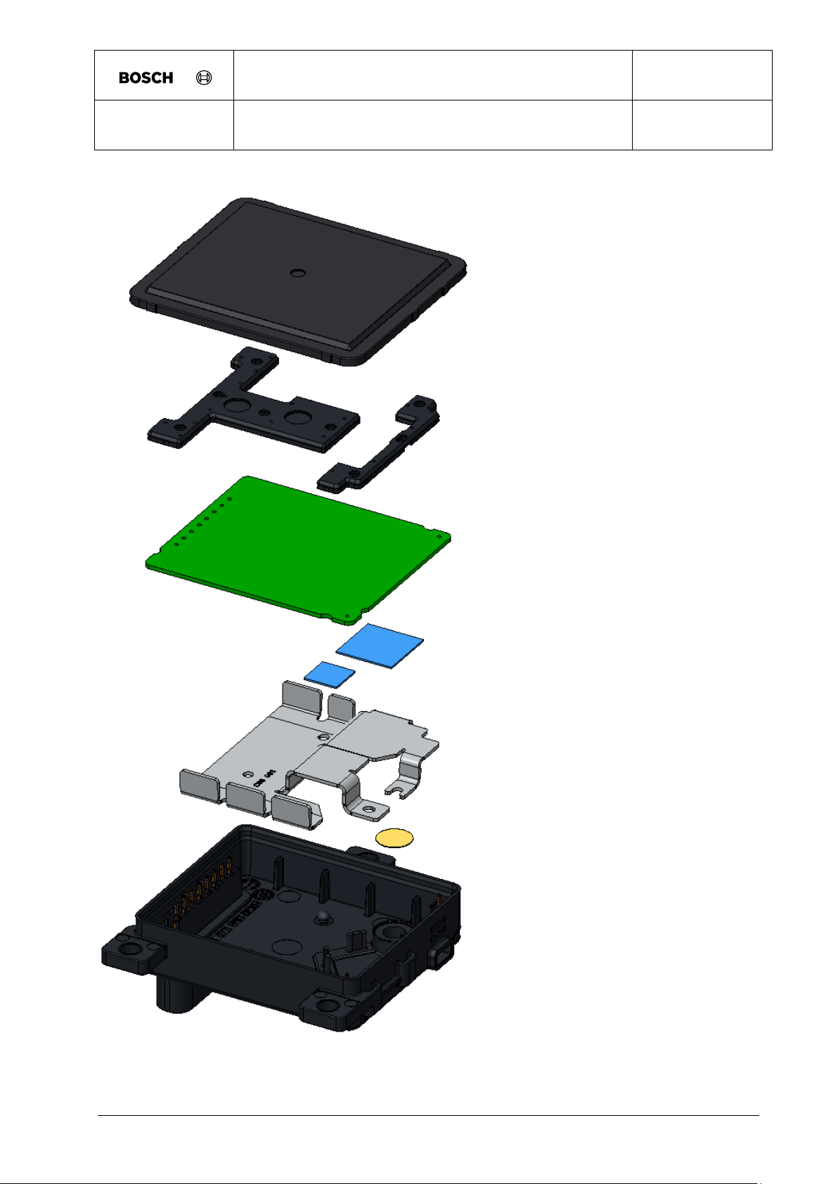
1.1.3. Preliminary Assembly concept
Figure: Assembly concept
© All rights reserved, Robert Bosch GmbH, also for the case of protected rights applications every power of disposal, like copy-right
and passing on rights, with us. The valid issue of this template is filed in CC-DA process landscape.

Technical Customer Documentation
Document version:
Refer to the Change history
CC-DA/ECR5
FR5CPEC
0265K60532
Page:
6
With only 3 main components (radome, PCB, lower housing), the assembly of the FR5CP SCU
is quite simple and is focusing to robust and cost effective mass production.
1.2. Labeling of the product
The radar devices provides information about:
- part-number
- series-number
- hardware and software version
- barcode information
- production date
- radar emission release information
- customer information
1.2.1. Radio Frequency Homologation
1.2.1.1. Phrases and Markings
The following phrases and markings are part of the radio frequency homologation and have to
be reproduced in the vehicle user manual.
1.2.1.1.1. Australia
1.2.1.1.2. Qatar
1.2.1.1.3. South Africa
1.2.1.1.4. Singapore
1.2.1.1.5. Ukraine
1.2.1.1.6. Serbia
1.2.1.1.7. Moldova
1.2.1.1.8. Mexico
1.2.1.1.9. Phillipines
© All rights reserved, Robert Bosch GmbH, also for the case of protected rights applications every power of disposal, like copy-right
and passing on rights, with us. The valid issue of this template is filed in CC-DA process landscape.
1.2.1.1.10. Indonesia
1.2.1.1.11. Brunei Daressalam
1.2.1.1.12. Jordania

Technical Customer Documentation
Document version:
Refer to the Change history
CC-DA/ECR5
FR5CPEC
0265K60532
Page:
7
1.2.1.1.13. United Arabic Emirates
1.2.1.1.14. Morocco
1.2.1.1.15. Malaysia
1.2.1.1.16. South Korea
1.2.1.1.17. Brazil
1.2.1.1.18. Taiwan
1.2.1.1.19. China
1.2.1.1.20. Hong Kong
1.2.1.1.21. Japan
1.2.1.1.22. Europe
1.2.1.1.23. USA
Once FCC approval is granted for FR5CPEC, the following FCC ID has to be included in
the vehicle user manual and labelled on the product.
FCC ID: NF3-FR5CPEC
The following warning text for RF equipment has to be included in the vehicle user
manual:
User Manual statement according to §15.19
This device complies with Part 15 of the FCC Rules. Operation is subject to the following two
conditions:
1. this device may not cause harmful interference, and
2. this device must accept any interference received, including interference that
3. may cause undesired operation.
User Manual statement according to §15.21:
Changes or modifications made to this equipment not expressly approved by Robert BOSCH
GmbH may void the FCC authorization to operate this equipment.
User Manual statement according to §15.105:
This equipment has been tested and found to comply with the limits for a Class A digital device,
pursuant to Part 15 of the FCC Rules. These limits are designed to provide reasonable
protection against harmful interference when the equipment is operated in a commercial
© All rights reserved, Robert Bosch GmbH, also for the case of protected rights applications every power of disposal, like copy-right
and passing on rights, with us. The valid issue of this template is filed in CC-DA process landscape.

Technical Customer Documentation
Document version:
Refer to the Change history
CC-DA/ECR5
FR5CPEC
0265K60532
Page:
8
environment. This equipment generates, uses, and can radiate radio frequency energy and, if
not installed and used in accordance with the instruction manual, may cause harmful
interference to radio communications. Operation of this equipment in a residential area is likely
to cause harmful interference in which case the user will be required to correct the interference
at his own expense.
RF Exposure Information according 2.1091 / 2.1093 / KDB 447498 / OET bulletin 65:
Radio frequency radiation exposure Information:
This equipment complies with FCC radiation exposure limits set forth for an uncontrolled
environment. This equipment should be installed and operated with minimum distance of 20 cm
between the radiator and your body. This transmitter must not be co-located or operating in
conjunction with any other antenna or transmitter.
1.2.1.1.24. Canada
Once Canada approval is granted for FR5CPEC the following ISED certification number,
PMN and HVIN has to be included in the vehicle user manual and labelled on the product
on the product.
IC: 3887A-FR5CPEC
HVIN: FR5CPEC
PMN: Front Radar 5 Car Plus Ethernet CAN
The following warning text for RF equipment has to be included in the vehicle user
manual:
RF equipment according to RSS_GEN in English and French language
This device complies with Industry Canada license-exempt RSS standard(s). Operation is
subject to the following two conditions: (1) this device must not cause interference, and (2) this
device must accept any interference, including interference that may cause undesired operation
of the device.
Le présent appareil est conforme aux CNR d'Industrie Canada applicables aux appareils radio
exempts de licence. L'exploitation est autorisée aux deux conditions suivantes: (1) l'appareil ne
doit pas produire de brouillage, et (2) l'utilisateur de l'appareil doit accepter tout brouillage
radioélectrique subi, même si le brouillage est susceptible d'en compromettre le
fonctionnement.
© All rights reserved, Robert Bosch GmbH, also for the case of protected rights applications every power of disposal, like copy-right
and passing on rights, with us. The valid issue of this template is filed in CC-DA process landscape.

Technical Customer Documentation
Document version:
Refer to the Change history
CC-DA/ECR5
FR5CPEC
0265K60532
Page:
9
RF Exposure Information according to RSS-102 in English and French language:
This equipment complies with FCC and IC radiation exposure limits set forth for an uncontrolled
environment. This equipment should be installed and operated with minimum distance of 20 cm
between the radiator and your body. This transmitter must not be co-located or operating in
conjunction with any other antenna or transmitter.
Cet équipement est conforme aux limites d'exposition aux rayonnements IC établies pour un
environnement non contrôlé. Cet équipement doit être installé et utilisé avec un minimum de 20
cm de distance entre la source de rayonnement et votre corps. Ce transmetteur ne doit pas etre
place au meme endroit ou utilise simultanement avec un autre transmetteur ou antenne.
1.2.1.1.25. Argentina
1.3. Dimensions and weights
Outside dimension:
Box volume, total Length (depth in X-direction) = 18.7 mm
Detailed dimensions see offer drawing.
Outside dimension:
Box volume, total Width = 62.6mm
Detailed dimensions see offer drawing.
Outside dimension:
Box volume, total Height = 72mm
Detailed dimensions see offer drawing.
Maximum weight of complete SCU (w/o heating) w/o mounting device and poka yoke element
>80gr.
© All rights reserved, Robert Bosch GmbH, also for the case of protected rights applications every power of disposal, like copy-right
and passing on rights, with us. The valid issue of this template is filed in CC-DA process landscape.

Technical Customer Documentation
Document version:
Refer to the Change history
CC-DA/ECR5
FR5CPEC
0265K60532
Page:
10
Symbol Parameter
Note or Test Condition
min typ max Unit
P_RF_on operating power consumption
- RF on, approx. 30%
duty cycle
- COM Interfaces ON
- Processing Unit: M
- VBATT=14V +/- 5%
- 4 W
Symbol Parameter
Note or Test Condition
min typ max Unit
P_RF_off operating power consumption
- RF off
- COM Interfaces ON
- Processing Unit: M
- VBATT=14V +/- 5%
- 2,5 W
1.4. Power consumption / power output
This section describes the power consumption of the SCU for different operating states.
1.5. General remarks for service, repair and maintenance
Repair and maintainance of the product is not allowed
Sensor can`t be opened without damageing.
In case of service the Sensor needs to be replaced.
1.6. Information on disposal and recycling
All Materials are released regarding the following regulations:
- ELV (Altautorichtlinie) and GADSL (BBM)
- RoHS
- REACh
© All rights reserved, Robert Bosch GmbH, also for the case of protected rights applications every power of disposal, like copy-right
and passing on rights, with us. The valid issue of this template is filed in CC-DA process landscape.

Technical Customer Documentation
Document version:
Refer to the Change history
CC-DA/ECR5
FR5CPEC
0265K60532
Page:
11
2. System description
2.1. Vehicle integration interfaces
This chapter describes the requirements for all parts mounted in front or around the sensor, like
painted bumper, unpainted cover and emblem/radome, regarding RF integration at 77 GHz with
FR5plus radar sensors.
Values are marked with t.b.c. or t.b.d. showing that they have to be confirmed or defined during
the development process.
As product development is an on-going process, we reserve the right to make amendments in
line with technical progress.
The radar sensor performance should be influenced as low as possible by the installation
behind a fascia. Therefore the two-way radar loss by the fascia should be as low as possible
and the reflection attenuation must fulfill the requirements listed below.
Vertical misalignment will cause additional attenuation reducing the maximum range.
Horizontal misalignment will cause reduced detection at higher azimuth angles.
Ghost target detection caused by interference signals of multiple reflection at fascia and metallic
parts of the vehicle must be avoided. A simulation can be offered to evaluate the risk and the
need of using absorber material to suppress this unwanted signal. Because the threshold of
detection is very low, a high attenuation is required. Plastic material can only achieve high
enough attenuation, if carbon black is added.
2.1.1.1. Radar Cone
Radar Cone for PLUS Family
The radar cone describes the zone where the fascia has to be optimized. Any parts of the
vehicle inside the radar cone may influence the radar performance. Cables, brackets, bars etc.
should not touch the radar cone. The fascia in this zone may not have bends and edges as well
as changes in thickness or material or painting.
Based on the footprint on the top side of the radar PCB the cone is characterized by a vertical
and a horizontal opening angle. The footprint is centered regarding to the sensor housing. A
CAD model of the radar cone is available.
The footprint for radar cone has the following dimensions: (W x H) 55 mm x 55 mm
© All rights reserved, Robert Bosch GmbH, also for the case of protected rights applications every power of disposal, like copy-right
and passing on rights, with us. The valid issue of this template is filed in CC-DA process landscape.

Technical Customer Documentation
Document version:
Refer to the Change history
CC-DA/ECR5
FR5CPEC
0265K60532
Page:
12
Figure: Footprint of the radar cone. For better visibility the footprint is shown on top of the
sensor housing.
Radar cone definition for covered installation (FR5CP):
The horizontal opening angle depends on the angle range that is evaluated by the sensor in
azimuth and elevation, whereby the opening angle of the radar cone has to be larger than the
angle range that is evaluated. For covered integration the radar cone is 10° larger than the used
angle range that is evaluated by the sensor.
Radar cone:
±70°
(1)
in horizontal direction (not including misalignment)
± 20° in vertical direction (not including misalignment)
(1)
Valid for angle measurement range of ±60°
© All rights reserved, Robert Bosch GmbH, also for the case of protected rights applications every power of disposal, like copy-right
and passing on rights, with us. The valid issue of this template is filed in CC-DA process landscape.

Technical Customer Documentation
Document version:
Refer to the Change history
CC-DA/ECR5
FR5CPEC
0265K60532
Page:
13
2.1.1.2. Fascia design guidelines
Material
Material with low dielectric constant (r) and low dielectric loss factor tanδ at 77 GHz should be
used. Recommended are materials based on polypropylene (PP) and polymethyl methacrylate
(PMMA), while materials like polycarbonate (PC) and acrylonitrile butadiene styrene (ABS) are
still ok. The material shall be homogenous, compounds including glass fiber, carbon fiber or
metal particles are not recommended.
The fascia shall be designed for radar transparency. The thickness shall be a multiple of the half
wavelength (in the material) to minimize the influence of the fascia. The quality criteria of radar
transparency is the reflection coefficient of the radome/fascia. Tolerances of the overall
thickness and the dielectric constant of the used material influence the amount of reflection at
the radome/fascia. Additional influence occurs due to curvature of the fascia. Therefore the
radius has to be as large as possible. With sharp edges the negative influence will increase
significantly. Not allowed are ribs, structures and steps changing the thickness of the
radome/fascia.
Painting
The layer structure of the painting, typically made of three painting layers consisting of primer,
base coating and clear coating, will increase the effective permittivity value
and dielectric
r,eff
loss factor tanδ of the painted plate used as fascia.
Fascia Classification (FR5CP)
The two-way radar loss caused by fascia should be as low as possible. High losses decrease
the sensor performance regarding range and angle estimation. Therefore it is recommended to
achieve a two-way radar loss below 3 dB.
© All rights reserved, Robert Bosch GmbH, also for the case of protected rights applications every power of disposal, like copy-right
and passing on rights, with us. The valid issue of this template is filed in CC-DA process landscape.

Technical Customer Documentation
Document version:
Refer to the Change history
CC-DA/ECR5
FR5CPEC
0265K60532
Page:
14
1. Reflection coefficient <-15 dB
is achieved when fascia has optimized thickness within a tolerance of ±0.1 mm and permittivity
within a tolerance of ±0.02. Dielectric loss factor tanδ shall be <0.01. With such low reflection a
vertical tilt angle of 0° is possible. This is the case for unpainted or a single e.g. black paint cover.
Also well designed emblems without air gap inside may be usable.
2. Reflection coefficient <-10 dB
is achieved when fascia has optimized thickness within a tolerance of ±0.2 mm and permittivity
within a tolerance ±0.02. Dielectric loss factor tanδ shall be <0.03. With such reflection a vertical tilt
angle of 0° must be avoided.
3. Reflection coefficient <-6 dB
is achieved when fascia has optimized thickness within a tolerance of ±0.2 mm and permittivity
within a tolerance of ±0.2. Dielectric loss factor tanδ shall be <0.05. With such reflection a vertical
tilt angle of >18° is required. This is the case for painted bumper especially when various colors are
used.
4. Reflection coefficient >-6 dB
is achieved when fascia has no optimized thickness or a painting with high metallic content is used.
The attenuation will exceed the maximum allowed limit.
Classification of reflection caused by the fascia
The examples described in the classification of reflection are derived from evaluation of flat
plates with constant thickness and homogeneous material. Deviations from this situation may
cause a change in classification and the vertical tilt angle of fascia has to be increased.
Surface Properties of the fascia
The surfaces of the fascia shall not exceed an average roughness height of 20 µm
(corresponding to ISO 1302 class N10; VDI 3400 class 45).
© All rights reserved, Robert Bosch GmbH, also for the case of protected rights applications every power of disposal, like copy-right
and passing on rights, with us. The valid issue of this template is filed in CC-DA process landscape.

Technical Customer Documentation
Document version:
Refer to the Change history
CC-DA/ECR5
FR5CPEC
0265K60532
Page:
15
2.1.1.3. Installation Hints
To enable the full performance of the radar sensor, it is recommended to use the following
installation hints and guidelines for the RF integration of the sensor.
Sensor rotation around radome normal (FR5CP)
The sensor shall not be rotated more than 1.5° around the normal of the radome surface.
Maximum angle between radar cone and fascia
The angle α between the radar beam inside the radar cone and the fascia may not be larger
than 70° anywhere inside the radar cone.
Figure: Maximum angle between fascia and radar cone
© All rights reserved, Robert Bosch GmbH, also for the case of protected rights applications every power of disposal, like copy-right
and passing on rights, with us. The valid issue of this template is filed in CC-DA process landscape.

Technical Customer Documentation
Document version:
Refer to the Change history
CC-DA/ECR5
FR5CPEC
0265K60532
Page:
16
Minimum distance between sensor and fascia
The minimum distance between the sensor radome and the fascia or any other part of the
vehicle may not be smaller than 5 mm.
This is valid for fascia parts fulfilling the following requirements.
Figure: Minimum distance above sensor radome
Vertical tilt of fascia (FR5CP)
The vertical tilt angle between the sensor normal and the surface normal of the fascia shall be in
the range according to the following table.
Figure: vertical tilt angle of fascia to sensor normal
© All rights reserved, Robert Bosch GmbH, also for the case of protected rights applications every power of disposal, like copy-right
and passing on rights, with us. The valid issue of this template is filed in CC-DA process landscape.

Technical Customer Documentation
Document version:
Refer to the Change history
CC-DA/ECR5
FR5CPEC
0265K60532
Page:
17
Minimum
vertical tilt
reflection
coefficient
max. tolerance
thickness
tolerance ε
r
tanδ application
<-15 dB ±0.1 mm ±0.02 <0.01
unpainted,
(black)
painting,
embleme
±0.2 mm ±0.02 <0.03
unpainted,
(black)
painting,
embleme
±0.1 mm ±0.2 <0.03
painted
bumper
>18° <-6 dB ±0.2 mm ±0.2 <0.05
painted
bumper
>8°
<-10 dB
Table: minimum vertical tilt angle of fascia to sensor normal
Curvature of fascia for FR5CP
Curvature of the fascia may influence the radar performance, especially with low vertical tilt
angles. The minimum radius of the curvature shall be according to the following rules:
R > 350 mm, no significant influence expected
R < 350 mm, significant influence possible, has to be evaluated
R < 200 mm, significant influence expected, not recommended
Absorber around the sensor
It is highly recommended to use a cone made of absorber material around the radar cone of the
sensor to prevent ghost targets. The design of the absorber cone must fulfill the following
design guidelines (reflection from outside the radar cone, multipath reflection).
Reflection from outside the radar cone
Reflections from structures located outside the radar cone have to be avoided.
Furthermore interference signals picked up by the sensor antennas should be avoided by
keeping a minimum distance (d) of 5 mm to 10 mm for parts in front of the sensor.
Even with compliance to the radar cone, reflections at parts outside the radar cone may disturb
the received signal. Reflections at parts causing an interference signal to the receiving antenna
and reflections at parts getting to the receiving antenna after a second reflection at the fascia
(multipath reflection).
© All rights reserved, Robert Bosch GmbH, also for the case of protected rights applications every power of disposal, like copy-right
and passing on rights, with us. The valid issue of this template is filed in CC-DA process landscape.

Technical Customer Documentation
Document version:
Refer to the Change history
CC-DA/ECR5
FR5CPEC
0265K60532
Page:
18
Closed surfaces of brackets and masks made of metal or high reflecting material need a tilt
angle being arranged that the reflection is not received by the receiving antennas of the sensor.
Figure: Reflection at bracket or mask
For closed surfaces (masks) in azimuth, the angle between mask surface and the normal
vector n of the sensor shall be above 75° for parts outside of the radar cone.
For closed surfaces (masks) in elevation, the angle between mask surface and the normal
vector n of the sensor shall be above 20° for parts outside of the radar cone.
Multipath reflection
Reflections of incoming signals at bracket or shielding absorber are coming back to the sensor if
reflection at the bumper occurs. The figure below shows the situation which should be avoided.
The worst case happens if the combination of the vertical tilt angles of shielding and bumper is
1 = 2 / 2 . For a low interference signal the condition shall be:
1 > 2 / 2 +10°
or
1 < 2 / 2 -10°
© All rights reserved, Robert Bosch GmbH, also for the case of protected rights applications every power of disposal, like copy-right
and passing on rights, with us. The valid issue of this template is filed in CC-DA process landscape.

Technical Customer Documentation
Document version:
Refer to the Change history
CC-DA/ECR5
FR5CPEC
0265K60532
Page:
19
Figure: a) Requirements for parts outside radar cone to avoid multipath reflection
The same requirements are valid for a horizontal tilt of the fascia.
3. Technical data with measured variables and measuring conditions
3.1. Mechanical characteristics
Gravel bombardment:
According to ISO 20567-1 against back housing (covered installation)
Mechanical shock:
According to DIN EN 60068-2-27
500m/s^2 / 6ms duration
Mechanical vibration (broadband random vibration):
According to DIN EN 60068-2-64
Frequencyspectrum 5 Hz - 2000 Hz according to the following profile
© All rights reserved, Robert Bosch GmbH, also for the case of protected rights applications every power of disposal, like copy-right
and passing on rights, with us. The valid issue of this template is filed in CC-DA process landscape.

Technical Customer Documentation
Document version:
Refer to the Change history
CC-DA/ECR5
FR5CPEC
0265K60532
Page:
20
a
= 30.8 m/s²
eff
Protection class:
According to International Protection Marking, ISO 20653
IP6Kx, IPx6K, IPx7, IPx9K
Temperature range with restricted operation (communication interface working):
Top_max=+85°C ... Tmax=+95°C.
Temperature range of operation:
Top_min= -40°C ... Top_max=+85°C.
Duration see Reliability
Temperature range of operation:
Top_min= -40°C ... Top_max=+85°C.
Duration see Reliability
Corrosion resistance against salt spray and humidity
According to DIN EN 60068-2-11
Sensor may not be exposed to direct UV light for more than 48h
3.2. Electrical characteristics
The chapter electrical car integration describes the vehicle connector interface of the Radar
SCU.
The detailed description of the following connection topics are adapted to the defined feature
configuration:
- Connector Pinning
© All rights reserved, Robert Bosch GmbH, also for the case of protected rights applications every power of disposal, like copy-right
and passing on rights, with us. The valid issue of this template is filed in CC-DA process landscape.

Technical Customer Documentation
Document version:
Refer to the Change history
CC-DA/ECR5
FR5CPEC
0265K60532
Page:
21
Pin No. Designation Description
1 COM2-L Ethernet (ETH_TRXN)
2 COM2-H Ethernet (ETH_TRXP)
3 Spare not used
4 Spare not used
5 GND Sensor ground: connected to terminal 31
6 COM1-L Communication interface 1: Low signal
7 COM1-H Communication interface 1: High signal
8 VBATT Supply voltage for sensor (terminal 15/30)
- Connector Power Supply Interface
- Connector Communication Interface
- Connector Multi-Purpose I/O Interface
3.2.1. Electrical Vehicle Connector Pinning
This section describes the SCU vehicle connector pin properties and the connector pinning.
3.2.1.1. Pin Properties
Every connector pin is robust against short circuits to the supply voltage, to GND and to the
neighbour pins. The resistance of the short circuit may be as low as 0,1 Ohm.
An unwanted supply of the ECU by any other pins than the dedicated power supply pins is
impossible.
The ECU is robust against 5 kOhm shunt between adjacent pins of the vehicle connector
caused by dirt. No disturbance of the functionality.
3.2.1.2. Pin Assignment
Vehicle connector pin number assignment
© All rights reserved, Robert Bosch GmbH, also for the case of protected rights applications every power of disposal, like copy-right
and passing on rights, with us. The valid issue of this template is filed in CC-DA process landscape.

Technical Customer Documentation
Document version:
Refer to the Change history
CC-DA/ECR5
FR5CPEC
0265K60532
Page:
22
V5COM
Buck
Switching
Regulator SR1
SDN1
V3LN
V3MMIC
LR
3,3V
LR-LN
3,3V
Vbatt1
Vbatt-
monitoring-
switch
Vbatt-mon
Vbatt3
V3MMIC-in
Boost
Switching
Regulator
SR3
Vbatt2
V3LN-in
Buck
Switching
Regulator SR2
SDN2
SDN3
V5COM-SW
V5COM
switch
V4
V3DIG
GND
Vbatt
3.2.2. Vehicle Power Supply
3.2.2.1. Constraints and Definitions
The car battery supplies power to the Sensor (terminal 15/30)
All power supply parameters are measured at the ECU vehicle connector supply pins (VBATT
to GND) unless different specified.
All power supply parameters are guaranteed and designed over ambient temperature Ta=
Ta_min to Ta_max unless different specified. (-40°C to 85°C, see Chapter "Operating
Environment")
All power supply parameters are guaranteed and designed over lifetime unless different
specified.
All power supply values are continuous values.
Definition COM Interfaces ON:
COM interfaces are working according to the respective communication standard.
3.2.2.2. Power Supply System 12V
The equivalent circuit diagram of the VBATT - Interface is as follows:
© All rights reserved, Robert Bosch GmbH, also for the case of protected rights applications every power of disposal, like copy-right
and passing on rights, with us. The valid issue of this template is filed in CC-DA process landscape.

Technical Customer Documentation
Document version:
Refer to the Change history
CC-DA/ECR5
FR5CPEC
0265K60532
Page:
23
Symbol Parameter Note or Test Condition min typ max Unit
Umin
min. voltage without
damageing the ECU
- reverse polarity
- t <= 60s
- Ri < 30mOhm
- 14,28 - 14,00 V
Symbol Parameter Note or Test Condition min typ max Unit
Umax_res_up
max. reset voltage Power
Up
- - 6,0 V
Symbol Parameter Note or Test Condition min typ max Unit
Umin_res_dn
min. reset voltage Power
Down
4,5 - - V
Symbol Parameter Note or Test Condition min typ max Unit
Umin_com min. communication voltage
- COM Interfaces ON
- Object list preservation
- min value Power Down
- max value Power Up
5,5 - 6 V
Symbol Parameter Note or Test Condition min typ max Unit
Umin_op min. operating voltage
- COM Interfaces ON
- RF Module ON
- - 7,0 V
Symbol Parameter Note or Test Condition min typ max Unit
U_heating
radome heating operating
voltage
Ta= - 25°C to 25°C 9 - Umax_op V
Symbol Parameter Note or Test Condition min typ max Unit
Umax_op max. operating voltage
- COM Interfaces ON
- RF Module ON
16 - - V
Symbol Parameter Note or Test Condition min typ max Unit
Umax_com
max. communication
voltage
- COM Interfaces ON
- Object list preservation
see
Umax_op
see
Umax_op
see
Umax_op
V
Symbol Parameter Note or Test Condition min typ max Unit
Umax
max. voltage without
damageing the ECU
- - 35 V
The inrush-current is below 30 A. It decays to 10 % of the maximum value within 150 µs.
Condition: V_Batt=14.0V, 5m wire harness length, 0.5mm²
© All rights reserved, Robert Bosch GmbH, also for the case of protected rights applications every power of disposal, like copy-right
and passing on rights, with us. The valid issue of this template is filed in CC-DA process landscape.

Technical Customer Documentation
Document version:
Refer to the Change history
CC-DA/ECR5
FR5CPEC
0265K60532
Page:
24
Component Typical Value Package Size Toleranze Voltage Rating Power Rating Current Rating
R1100 61.9R 0805 1% 400V 400mW R1101 61.9R 0805 1% 400V 400mW C1100 4.7nF 0603 10% 100V - L1100 100µH 1210 +50/-30% 80V - 150mA
R1120 not populated 0402 - - - R1121 not populated 0402 - - - D1100 not populated SOT323-3L - - - -
3.2.3. Electrical Communication Interface
3.2.3.1. CAN1 Interface
The equivalent circuit diagram of the CAN1 - Interface is as follows:
typical values:
The CAN1 communication interface is compliant to CAN-HS according to ISO 11898-2: 2015
and ISO 11898-5:2007
The CAN1 communication interface is compliant to CAN-FD according to ISO 11898-2: 2015
and ISO 11898-5:2007
ISO7637-2 Electrical disturbances from conduction and coupling
© All rights reserved, Robert Bosch GmbH, also for the case of protected rights applications every power of disposal, like copy-right
and passing on rights, with us. The valid issue of this template is filed in CC-DA process landscape.

Technical Customer Documentation
Document version:
Refer to the Change history
CC-DA/ECR5
FR5CPEC
0265K60532
Page:
25
Component Typical Value Package Size Tolerance Voltage Rating Power Rating Current Rating
L1452 200uH 1210 - - - 50mA
R1451 1k 0805 1% 200V 0,4W R1452 1k 0805 1% 200V 0,4W R1453 100k 0603 1% 50V 0,1W C1450 100nF 0603 10% 50V - C1451 100nF 0603 10% 50V - C1453 4,7nF 0603 10% 100V - -
3.2.3.2. Ethernet Interface
The equivalent circuit diagram of the Ethernet - Interface is as follows:
The Ethernet communication interface is compliant to the IEEE100Base-T1
© All rights reserved, Robert Bosch GmbH, also for the case of protected rights applications every power of disposal, like copy-right
and passing on rights, with us. The valid issue of this template is filed in CC-DA process landscape.

Technical Customer Documentation
Document version:
Refer to the Change history
CC-DA/ECR5
FR5CPEC
0265K60532
Page:
26
Date
Template
Version
Description
Author Name
15.11.2017
1.0
Initial version, created according to the
requirements of the central directives CD-04504-
000, 1.3 and CD-04504-001 Definition of
contents, 1.3 and
reviewed by Bernd Landes (CC-DA/QMM1) and
Andre Reichmann (CC-DA/QMM1)
Mariana Georgieva-Grosse
(CC-DA/EPV1)
4. Change history of the template
© All rights reserved, Robert Bosch GmbH, also for the case of protected rights applications every power of disposal, like copy-right
and passing on rights, with us. The valid issue of this template is filed in CC-DA process landscape.
 Loading...