

ςТЎϩХʉ ЌТϾϦφЍʉ ʌμВТЎϺυ
ΖЎϩʉ ˒μВЖЙʉʓ ИͳϞφЁʑ
OBJ_BUCH-816-001.book Page 1 Wednesday, October 9, 2013 3:39 PM
Robert Bosch GmbH
Power Tools Division
70745 Leinfelden-Echterdingen
Germany
www.boschproductiontools.com
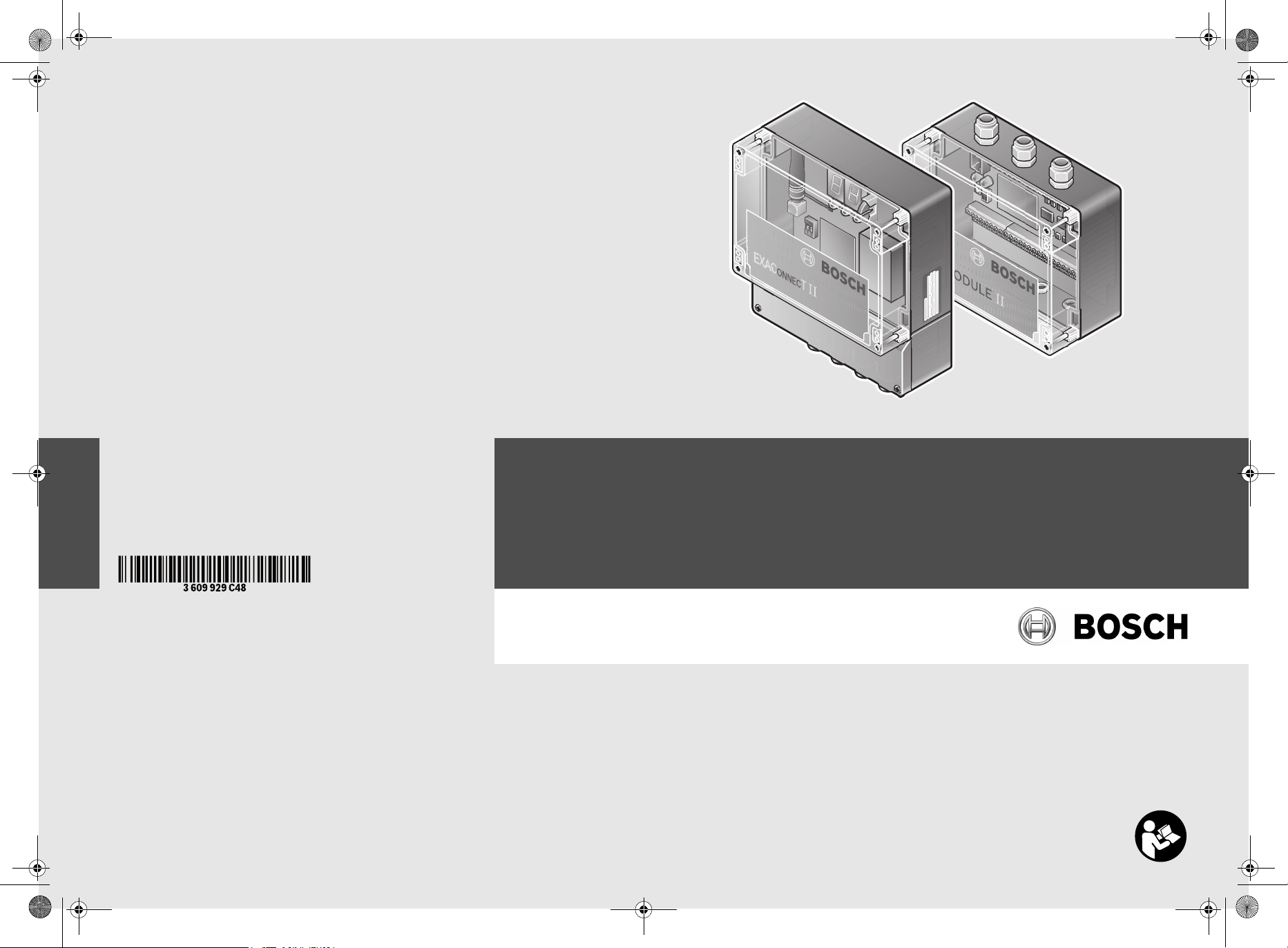
EXAConnecT II + I/O-Module II
3 609 929 C48 (2013.xx) PS / ## UNI
de Originalbetriebsanleitung
en Original instructions
fr Notice originale
es Manual original
pt Manual original
it Istruzioni originali
nl O orspronkelijke gebruiksaanwijzing
da Original brugsanvisning
sv Bruksanvisning i original
no Original driftsinstruks
fi Alkuperäiset ohjeet
el Πρωτότυπο οδηγιών χρήσης
tr Orijinal işletme talimatı
pl Instrukcja oryginalna
cs Původní návod k používání
sk Pôvodný návod na použitie
hu Eredeti használati utasítás
ru Оригинальное руководство по эк-
сплуатации
uk Оригінальна інструкція з
експлуатації
kk Пайдалану нұсқаулығының
түпнұсқасы
ro Instrucţiuni originale
bg Оригинална инструкция
mk Оригинално упатство за работа
sr Originalno uputstvo za rad
sl Izvirna navodila
hr Originalne upute za rad
et Algupärane kasutusjuhend
lv Instrukcijas oriģinālvalodā
lt Originali instrukcija
cn 正本使用说明书
tw 原始使用說明書
ko 사용 설명서 원본
th หนังสือคู่มือการใช้งานฉบับต้นแบบ
id Petunjuk-Pet unjuk untuk Penggunaan
Orisinal
vi Bản gốc hướng dẫn sử dụng
ar
fa
OBJ_BUCH-816-001.book Page 2 Wednesday, October 9, 2013 3:39 PM
2 |
Deutsch . . . . . . . . . . . . . . . . . . . . . . . . . . . . . . . . . . . . . . . . . Seite 10
English . . . . . . . . . . . . . . . . . . . . . . . . . . . . . . . . . . . . . . . . . . Page 25
Français . . . . . . . . . . . . . . . . . . . . . . . . . . . . . . . . . . . . . . . . . Page XX
Español . . . . . . . . . . . . . . . . . . . . . . . . . . . . . . . . . . . . . . . . Página XX
Português. . . . . . . . . . . . . . . . . . . . . . . . . . . . . . . . . . . . . . . Página XX
Italiano . . . . . . . . . . . . . . . . . . . . . . . . . . . . . . . . . . . . . . . . . Pagina XX
Nederlands . . . . . . . . . . . . . . . . . . . . . . . . . . . . . . . . . . . . . Pagina XX
Dansk . . . . . . . . . . . . . . . . . . . . . . . . . . . . . . . . . . . . . . . . . . . Side XX
Svenska . . . . . . . . . . . . . . . . . . . . . . . . . . . . . . . . . . . . . . . . . Sida XX
Norsk . . . . . . . . . . . . . . . . . . . . . . . . . . . . . . . . . . . . . . . . . . . Side XX
Suomi. . . . . . . . . . . . . . . . . . . . . . . . . . . . . . . . . . . . . . . . . . . . Sivu XX
Ελληνικά. . . . . . . . . . . . . . . . . . . . . . . . . . . . . . . . . . . . . . . . Σελίδα XX
Türkçe . . . . . . . . . . . . . . . . . . . . . . . . . . . . . . . . . . . . . . . . . Sayfa XX
Polski . . . . . . . . . . . . . . . . . . . . . . . . . . . . . . . . . . . . . . . . . . Strona XX
Česky . . . . . . . . . . . . . . . . . . . . . . . . . . . . . . . . . . . . . . . . . . Strana XX
Slovensky. . . . . . . . . . . . . . . . . . . . . . . . . . . . . . . . . . . . . . . Strana XX
Magyar . . . . . . . . . . . . . . . . . . . . . . . . . . . . . . . . . . . . . . . . . . Oldal XX
Русский . . . . . . . . . . . . . . . . . . . . . . . . . . . . . . . . . . . . . Страница XX
Українська. . . . . . . . . . . . . . . . . . . . . . . . . . . . . . . . . . . Сторінка XX
Қазақша. . . . . . . . . . . . . . . . . . . . . . . . . . . . . . . . . . . . . . . . . . .Бет XX
Română . . . . . . . . . . . . . . . . . . . . . . . . . . . . . . . . . . . . . . . . Pagina XX
Български . . . . . . . . . . . . . . . . . . . . . . . . . . . . . . . . . . . Страница XX
Македонски . . . . . . . . . . . . . . . . . . . . . . . . . . . . . . . . . . . Страна XX
Srpski. . . . . . . . . . . . . . . . . . . . . . . . . . . . . . . . . . . . . . . . . . Strana XX
Slovensko . . . . . . . . . . . . . . . . . . . . . . . . . . . . . . . . . . . . . . . Stran XX
Hrvatski . . . . . . . . . . . . . . . . . . . . . . . . . . . . . . . . . . . . . . Stranica XX
Eesti . . . . . . . . . . . . . . . . . . . . . . . . . . . . . . . . . . . . . . . . . Lehekülg XX
Latviešu . . . . . . . . . . . . . . . . . . . . . . . . . . . . . . . . . . . . . . Lappuse XX
Lietuviškai . . . . . . . . . . . . . . . . . . . . . . . . . . . . . . . . . . . . Puslapis XX
中文 . . . . . . . . . . . . . . . . . . . . . . 页 XX
中文 . . . . . . . . . . . . . . . . . . . . . . 頁 XX
한국어 . . . . . . . . . . . . . . . . . . . . . . . . 페이지 XX
ภาษาไทย. . . . . . . . . . . . . . . . . . . . . . . . . . . . . . . . . หน้า XX
Bahasa Indonesia . . . . . . . . . . . . . . . . . . . . . . . . . . . . . . Halaman XX
Tiếng Việt . . . . . . . . . . . . . . . . . . . . . . . . . . . . . Trang XX
. . . . . . . . . . . . . . . . . . . . . . . . . . . . . . XX
. . . . . . . . . . . . . . . . . . . . . . . . . . . . . . XX
3 609 929 C48 | (9.10.13) Bosch Power Tools
OBJ_BUCH-816-001.book Page 3 Wednesday, October 9, 2013 3:39 PM
2
5
4
3
2
| 3
6
1
2
0 602 491 003
33
28
32
31
30
29
28
7
2
8
2
34
28
35
27
28
0 602 491 004
Bosch Power Tools 3 609 929 C48 | (9.10.13)
OBJ_BUCH-816-001.book Page 4 Wednesday, October 9, 2013 3:39 PM
4 |
20
6
5
4 3
21
16
17 18 19
91514 12 11 10 913
0 602 491 003
3 609 929 C48 | (9.10.13) Bosch Power Tools
OBJ_BUCH-816-001.book Page 5 Wednesday, October 9, 2013 3:39 PM
-
TD
TD+
D
RD
RD+
GN
+
D
1IB-
1IA
1OZ-
1OY+
GN
33
32
31
ON
1 2
29
30
| 5
34
-
+
Y
A+
2IB-
2I
GND
2OZ
2O
+9-30V
4
3
IN1IN
D
D
2
GN
D
5
3
6
4
IN
IN
IN
IN
GN
GN
D
D
9
IN
IN8
IN7
IN10
IN11
IN12
GND
GN
GN
D
D
15
IN16
IN13
IN
IN14
GND
GN
GN
OUT2
OUT1
D
GND
GN
OUT
OUT
OUT5
OUT6
D
GN
GND
OUT7
OUT8
GND
OUT9
OUT10
OUT12
OUT11
OUT13
OUT14
D
GN
GND
OUT15
OUT16
3436
0 602 491 004
Bosch Power Tools 3 609 929 C48 | (9.10.13)
A
OBJ_BUCH-816-001.book Page 6 Wednesday, October 9, 2013 3:39 PM
6 |
A B
2
2
7
8
2
2
22
C D
19
9
22
M4 x 20
8
13
1224 11 23
Pin 1
Pin 8
25
11 12
E
PG
-
TD-
RD
TD+
RD+
ON
1 2
26
3 609 929 C48 | (9.10.13) Bosch Power Tools
PG
Y
A+
1IB-
1I
GND
1OZ-
1OY+
PG
30V
2IB-
9-
2IA+
GND
2OY+
GND
2OZ-
+
012
OBJ_BUCH-816-001.book Page 7 Wednesday, October 9, 2013 3:39 PM
| 7
F
G
EXAConnecT
RS422
RS422
1
2
GND
1
26
2
1
RS422
RS422
1
RS4222RS422
I/O-Module I/O-Module
26
27
H
27
27
GND
+9-30V
GND
+
OUT1
SPS
IN1
1
OUT
IN2
GND
OUT2-
OUT2+
. . .
IN3
IN4
GND
24V DC
37
OUT1
1
1+
IN
IN
OUT2
2
IN
3
GND
OUT
+
2
IN
OUT4
. . .
GND
24V DC
38
SPS
Bosch Power Tools 3 609 929 C48 | (9.10.13)

OBJ_BUCH-816-001.book Page 8 Wednesday, October 9, 2013 3:39 PM
8 |
I J
40
39
K
43
44
45
46 47
L
M N
41
RS422
RS232/USB
42
16
21
15
20
3 609 929 C48 | (9.10.13) Bosch Power Tools
OBJ_BUCH-816-001.book Page 9 Wednesday, October 9, 2013 3:39 PM
| 9
O P
49 48
17
Bosch Power Tools 3 609 929 C48 | (9.10.13)
OBJ_BUCH-816-001.book Page 10 Wednesday, October 9, 2013 3:39 PM
10 | Deutsch
Verwenden Sie Schraubsystem, Zubehör, Einsatzwerk-
Deutsch
Sicherheitshinweise
Allgemeine Sicherheitshinweise
WARNUNG
haltung der Sicherheitshinweise und Anweisungen können
elektrischen Schlag, Brand und/oder schwere Verletzungen
verursachen.
Bewahren Sie alle Sicherheitshinweise und Anweisungen
für die Zukunft auf.
Der in den Sicherheitshinweisen verwendete Begriff „Elektrowerkzeug“ bezieht sich auf netzbetriebene Elektrowerkzeuge
(mit Netzkabel) und auf akkubetriebene Elektrowerkzeuge
(ohne Netzkabel).
Arbeitsplatzsicherheit
Halten Sie Ihren Arbeitsbereich sauber und aufge-
räumt. Unordnung und unbeleuchtete Arbeitsbereiche
können zu Unfällen führen.
Arbeiten sie mit dem Schraubsystem Basisstation
EXAConnecT, I/O-Module und Industrie-Akkuschrauber BT-EXACT/ BT-ANGLE EXACT nicht in explosionsgefährdeter Umgebung, in der sich brennbare Flüssigkeiten, Gase oder Stäube befinden. Elektrowerkzeuge
erzeugen Funken, die den Staub oder die Dämpfe entzünden können.
Elektrische Sicherheit
Vermeiden Sie Körperkontakt mit geerdeten Oberflä-
chen wie von Rohren, Heizungen, Herden und Kühlschränken. Es besteht ein erhöhtes Risiko durch elektri-
schen Schlag, wenn Ihr Körper geerdet ist.
Zweckentfremden Sie das Kabel nicht, um die Basissta-
tion, das I/O-Module oder das Elektrowerkzeug zu tragen, aufzuhängen oder um den Stecker aus der Steckdose zu ziehen. Halten Sie das Kabel fern von Hitze, Öl,
scharfen Kanten oder sich bewegenden Geräteteilen.
Beschädigte oder verwickelte Kabel erhöhen das Risiko eines elektrischen Schlages.
Sicherheit von Personen
Seien Sie aufmerksam, achten Sie darauf, was Sie tun,
und gehen Sie mit Vernunft an die Arbeit mit einem
Schraubsystem. Benutzen Sie kein Schraubsystem,
wenn Sie müde sind oder unter dem Einfluss von Drogen, Alkohol oder Medikamenten stehen. Ein Moment
der Unachtsamkeit beim Gebrauch des Schraubsystems
kann zu ernsthaften Verletzungen führen.
Verwendung und Behandlung des Schraubsystems
Bewahren Sie unbenutzte Schraubsysteme außerhalb
der Reichweite von Kindern auf. Lassen Sie Personen
das Schraubsystem nicht benutzen, die mit diesem
nicht vertraut sind oder diese Anweisungen nicht gelesen haben. Schraubsysteme sind gefährlich, wenn sie von
unerfahrenen Personen benutzt werden.
Lesen Sie alle Sicherheitshinweise und
Anweisungen. Versäumnisse bei der Ein-
zeuge usw. entsprechend diesen Anweisungen. Berücksichtigen Sie dabei die Arbeitsbedingungen und
die auszuführende Tätigkeit. Der Gebrauch von
Schraubsystemen für andere als die vorgesehenen Anwendungen kann zu gefährlichen Situationen führen.
Sicherheitshinweise für Basisstationen und Erweiterungsmodule
GEFAHR! Achten Sie darauf, dass die Basisstation und
das I/O-Module nicht an die Stromversorgung angeschlossen ist, bevor Sie sie öffnen. Die Basisstation
muss komplett spannungsfrei sein, da sonst die Gefahr eines elektrischen Schlages besteht.
Halten Sie die Basisstation und das I/O-Module von Re-
gen oder Nässe fern. Das Eindringen von Regen oder Näs-
se in die Basisstation oder das I/O-Module erhöht das Risiko eines elektrischen Schlages.
Halten Sie die Basisstation und das I/O-Module sauber.
Durch Verschmutzung besteht die Gefahr eines elektrischen Schlages.
Überprüfen Sie vor jeder Benutzung Basisstation, I/O-
Module, Kabel und Stecker. Benutzen Sie die Basisstation und das I/O-Module nicht, sobald Sie Schäden feststellen. Lassen Sie sie nur von qualifiziertem Fachpersonal und nur mit Original-Ersatzteilen reparieren.
Beschädigte Basisstationen, I/O-Module’s, Kabel und Stecker erhöhen das Risiko eines elektrischen Schlages.
Der Anschluss der Basisstation EXAConnecT und der
externen Geräte (Personal Computer, I/O-Module, Signallampe, Scanner, etc.) darf aufgrund der Komplexität der elektrischen Schaltungen nur von in der
Elektro-/Informationstechnik geschultem Personal
durchgeführt werden. Ansonsten ist die Sicherheit der
Bedienperson und der Geräte nicht gewährleistet.
Lesen und beachten Sie strikt die Sicherheits- und Ar-
beitshinweise in der Betriebsanleitung der von Ihnen
verwendeten Schrauber BT-EXACT/BT-ANGLE EXACT.
3 609 929 C48 | (9.10.13) Bosch Power Tools

OBJ_BUCH-816-001.book Page 11 Wednesday, October 9, 2013 3:39 PM
Produkt- und Leistungsbeschreibung
Lesen Sie alle Sicherheitshinweise und Anweisungen. Versäumnisse bei der Einhaltung
der Sicherheitshinweise und Anweisungen
können elektrischen Schlag, Brand und/oder
schwere Verletzungen verursachen.
Bestimmungsgemäßer Gebrauch
Das Bosch Schraubsystem BT-EXACT/ BT-ANGLE EXACT und
EXAConnecT ist bestimmt zum Eindrehen und Lösen von
Schrauben sowie zum Anziehen und Lösen von Muttern im angegebenen Abmessungs- und Leistungsbereich. Es ist nicht
bestimmt zum Dokumentieren von Drehmoment oder Drehwinkel einer Verschraubung.
Das i.O.- bzw. n. i.O.-Signal resultiert ausschließlich aus einem Abschaltsignal der mechanischen Abschaltkup plung, die
entsprechend kalibriert sein muss und ständige Nachprüfung
erfordert. Dieses i.O.- bzw. n.i. O.-Signal lässt keine Rückschlüsse auf die Verschraubungsqualität zu.
Diese Signale können mit der Basisstation EXAConnecT und
deren Software ausgewertet und dokumentiert werden. Eine
Änderung der Hard- und/oder Software oder der Anschluss
von Zusatzhardware schließt eine Haftung der Robert Bosch
GmbH grundsätzlich aus.
Länderspezifische Hinweise
Europäische Gemeinschaft
Dieses Schraubsystem darf in allen Ländern der Europäischen Gemeinschaft verwendet werden. In Frankreich wird
die Verwendung von Bluetooth nur geduldet. Bitte erkundigen Sie sich nach den Bestimmungen des Einsatzgebietes.
Nordamerika
Die Basisstation wurde geprüft und erfüllt die Grenzwerte für
ein Digitalgerät der Klasse A gemäß Teil 15 der Richtlinien der
amerikanischen Bundesbehörde für das Fernmeldewesen
(Federal Communications Commission). Diese Grenzwerte
stellen einen angemessenen Schutz gegen schädliche Funkstörungen sicher, wenn die Basisstation im gewerblichen Bereich eingesetzt wird. Die Basisstation erzeugt, verwendet
und kann Funkfrequenzenergie ausstrahlen, die bei nicht de r
Anleitung des Herstellers entsprechender Installation und
Verwendung der Basisstation Störungen des Funkempfangs
verursachen kann. Der Betrieb dieser Basisstation in einem
Wohngebiet verursacht wahrscheinlich schädliche Funkstörungen, die die Bedienperson auf eigenen Kosten beseitigen
lassen muss.
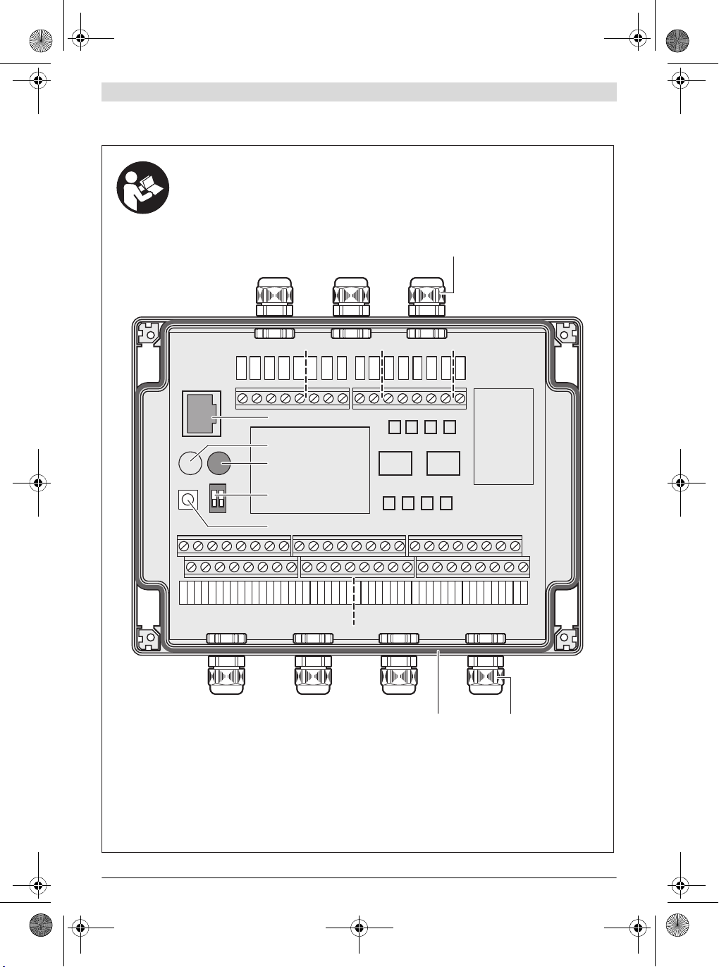
Abgebildete Komponenten
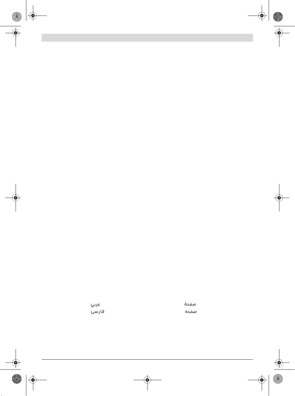
Die Nummerierung der abgebildeten Komponenten bezieht
sich auf die Darstellungen auf den Grafikseiten.
1 Basisstation EXAConnecT
2 Kreuzschlitzschrauben
3 Grüne LED-Anzeige (betriebsbereit)
4 Gelbe LED-Anzeige (Ethernet-Verbindung)
5 Blaue LED-Anzeige (Bluetooth-Verbindung)
6 Display: Anzeige für Statuscodes
7 Servicedeckel
8 Wartungsdeckel
9 Aussparungen zur Wandbefestigung
10 Dichtungsring
11 Kabelverschraubung (PG 16)
12 Kontermutter Kabelverschraubung
13 Erdungsklemme
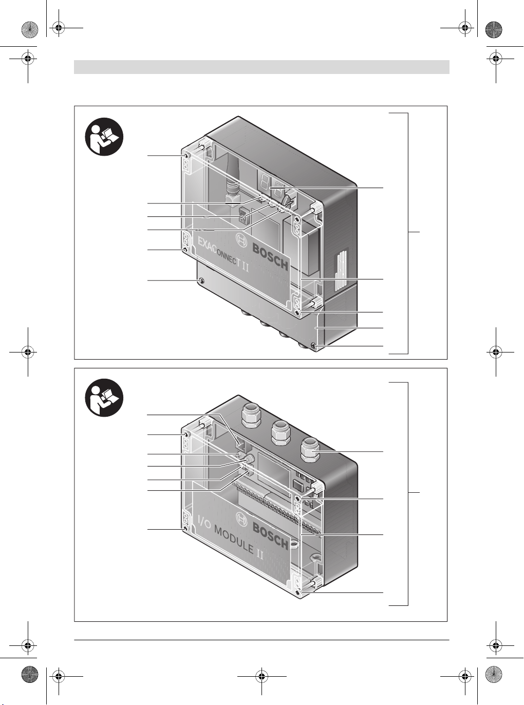
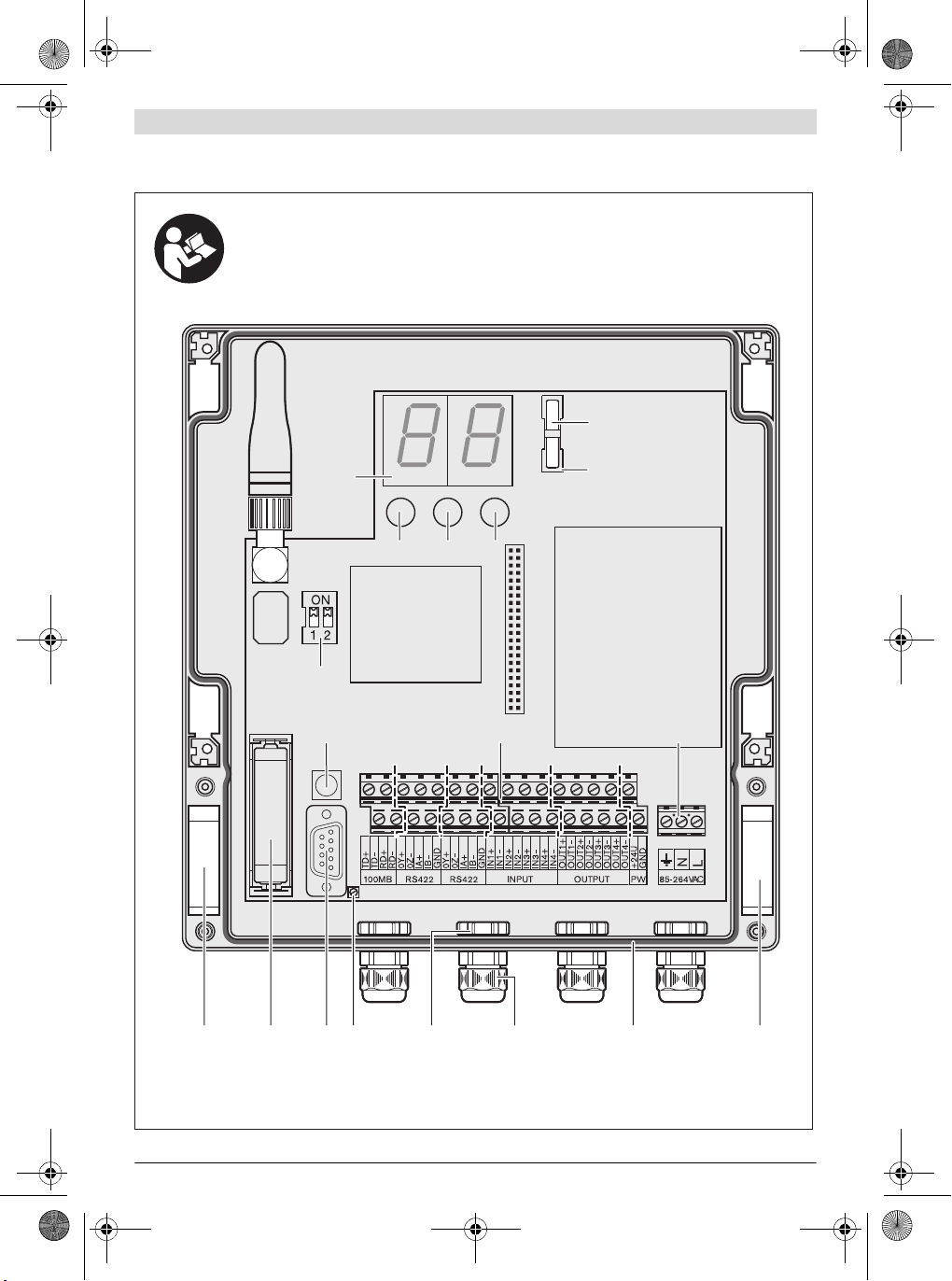
14 RS232-Schnittstelle
15 Pufferbatter ie
16 DIP-Schalter Basisstation
17 Reset-Taster Basisstation
18 Klemmleiste
19 Anschluss Energieversorgung
20 Knopfzelle für Echtzeituhr
21 Knopfzellen-Sockel
22 M4-Kreuzschlitzschrauben
23 Netzkabel (3-adrig) *
24 Kunststoffsteg zur Isolation des Anschlusses für die
Energieversorgung von den anderen Anschlüssen
25 Netzwerkkabel (Ethernet) *
26 Netzkabel (5-adrig) *
27 Erweiterungsmodul I/O-Module
28 Kreuzschlitzschrauben
29 DIP-Schalter I/O-Module
30 Reset-Taster I/O-Module
31 Rote LED-Anzeige (Fehler)
32 Grüne LED-Anzeige (betriebsbereit)
33 RJ45-Schnittstelle (Ethernet)
34 Kabelverschraubung (PG 16)
35 Servicedeckel
36 Dichtungsring
Optionale Systemerweiterungen
37 mechanischer Taster/Schalter
38 Signallampe
39 Freigabe-Taster *
40 Kabel des Freigabe-Tasters
41 Schnittstellenwandler
42 Barcode-Scanner (RS232 oder USB)
43 Gelbe Signallampe
44 Blaue Signallampe
45 Grüne Signallampe
46 Rote Signallampe
47 Externe Energieversorgung der Signallampe
Konfigurationssoftware
48 Symbolfeld Schrauber
Registerkarte Seriennummer Schrauber
49
*Abge bildetes oder beschriebenes Zubehör gehört nicht zum
Standard-Lieferumfang. Das vollständige Zubehör finden S ie in
unserem Zubehörprogramm.
Deutsch | 11
Bosch Power Tools 3 609 929 C48 | (9.10.13)
OBJ_BUCH-816-001.book Page 12 Wednesday, October 9, 2013 3:39 PM
12 | Deutsch
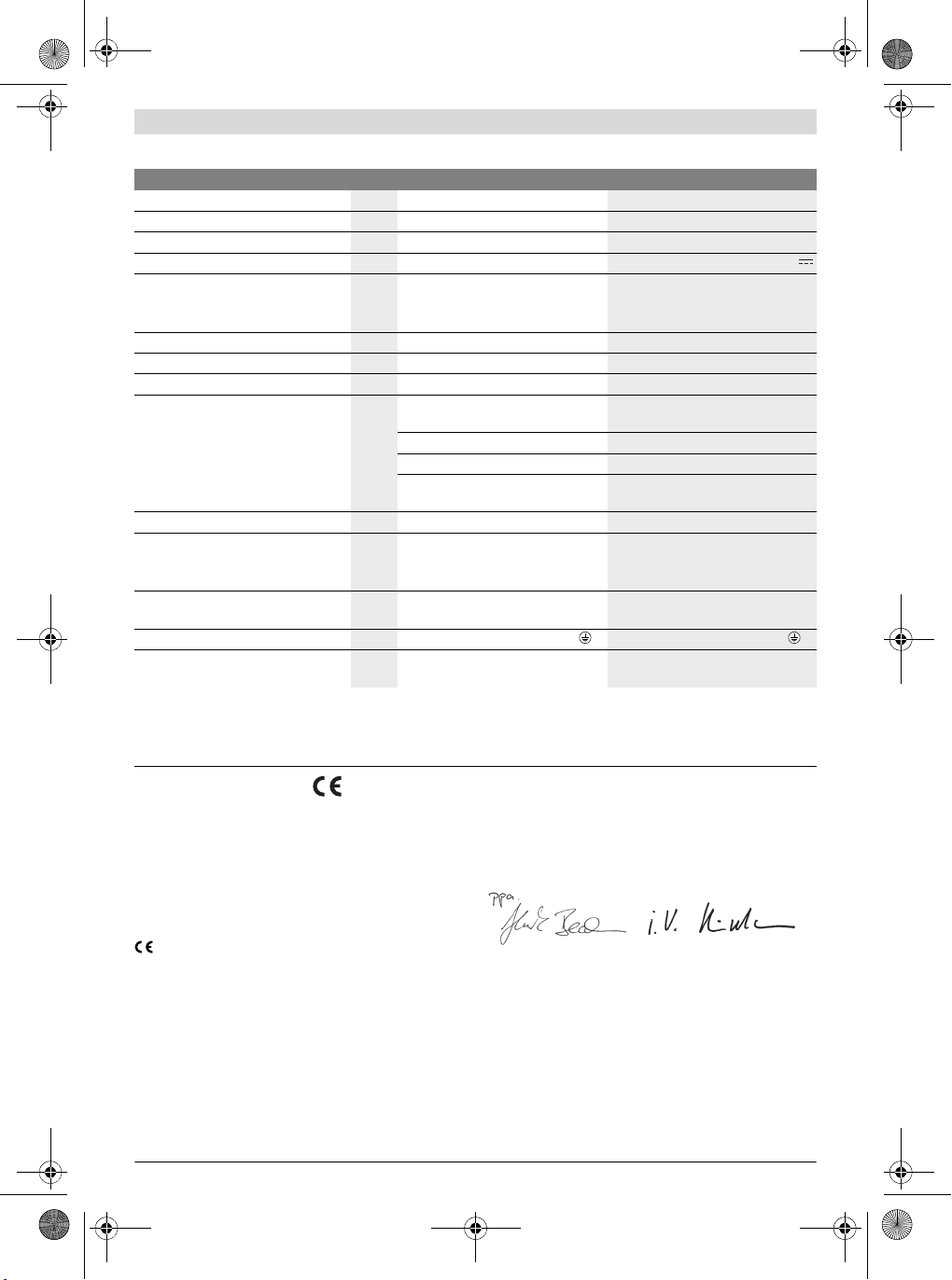
Technische Daten
Basisstation EXAConnecT Erweiterungsmodul I/O-Module
Sachnummer
Eingangsspannung
Eingangsstrom maximal
Eingangsfrequenz
Gleichstrom-Ausgang
V 100 –240 24
mA 150 200
Hz 50 –60
V
– Ausgangsspannung
– Ausgangsstrom maximal
mA
Lagertemperatur °C –20... 80 –20...80
Betriebstemperatur
Relative Luftfeuchte
Datenschnittstelle
°C 5–70 5–70
% 20 – 90 frei von Betauung 20 – 90 frei von Betauung
Bluetooth wireless technology
Klasse 2 (Spezifikation 1.2)
Übertragungsreichweite maximal
Pufferbatterien
m10,0* –
1,5 V (Standard-Mikrozelle AAA)
(3-V-Lithium-Batterie, CR 2032)
Gewicht entsprechend EPTA-Procedure 01/2003
kg 1,0 0,5
Schutzklasse
Schutzart
Bluetooth® ist ein eingetragenes Warenzeichen von Bluetooth SIG, Inc. (Special Interest Group) .
Die Angaben gelten für eine Nennspannung [U] von 230 V. Bei abweichenden Spannungen und in länderspezifischen Ausführungen können diese Angaben variieren.
* Die Übertragungsreichweite kann durch Umgebungsbedingungen beeinflusst werden. Wände aus oder mit Metall reduzieren die Übertragungsreichweite.
IP 54 (staub- und spritzwasserge-
Konformitätserklärung
Wir erklären in alleiniger Verantwortung, dass das unter
„Technische Daten“ beschriebene Produkt mit den folgenden
Normen oder normativen Dokumenten übereinstimmt:
IEC 60950-1:2005 + Corr. 1:2006 + A1:2009,
EN 300328 V.1.7.1, EN 300328 V.1.8.1:2012.09,
EN 301489-1:2008, EN 301489-3:2002
gemäß den Bestimmungen der Richtlinien 1999/5/EG,
2004/108/EG, 2011/65/EU.
05
WARNUNG! Der Betrieb dieser Basisstation kann in ei-
nem Wohngebiet Funkstörungen verursachen. In die-
sem Fall muss der Betreiber der Basisstatio n angemessene Maßnahmen zu deren Beseitigung durchführen.
0 602 491 003 0 602 491 004
24
200
RS422 (2x seriell)
RS422 (2x seriell)
RS232
Ethernet (1x)
(1x; mit 2 Anschlussmöglichkeiten)
Knopfzelle
/I /I
IP 54 (staub- und spritzwasserge-
schützt)
Technische Unterlagen bei:
Robert Bosch GmbH, PT/ETM9,
D-70745 Leinfelden-Echterdingen
Henk Becker
Executive Vice President
Engineering
Robert Bosch GmbH, Power Tools Division
D-70745 Leinfelden-Echterdingen
Leinfelden, XX.XX.2013
Helmut Heinzelmann
Head of Product Certification
PT/ETM9
Ethernet
schützt)
–
–
–
–
–
3 609 929 C48 | (9.10.13) Bosch Power Tools

OBJ_BUCH-816-001.book Page 13 Wednesday, October 9, 2013 3:39 PM
Montage
Betriebs- und Lagerungsumgebung
Die Basisstation sowie das I/O-Module ist ausschließlich für
den gewerblichen Betrieb an geschlossenen Einsatzorten geeignet. Für ihren einwandfreien Betrieb sollte die zulässige
Umgebungstemperatur zwischen 5 °C und 70 ° C (41 ° F und
158 ° F) liegen, bei einer zulässigen relativen Luftfeuchtigkeit
zwischen 20 und 90 % frei von Betauung.
Systemvoraussetzung
Die Basisstation EXAConnecT sowie das I/O-Module werden
ohne Kabel ausgeliefert und müssen vor Inbetriebnahme
fachgerecht verkabelt werden.
Für die Datenabfrage benötigen Sie zusätzlich einen PC mit
folgender Software:
–Betriebssystem Microsoft Windows XP, Vista, 7 oder 8
(32 und 64 Bit)
–aktuelle Webbrowser, die Java Runtime Environment
(JRE) ab Version 1.4 unterstützen
– Java Runtime Environment (JRE) ab Version 1.4
Anschlüsse der Basisstation
Die Konfiguration Ihres PCs/Systems wird in dieser Betriebsanleitung nicht erklärt. Auch zum Anschluss von beispielsweise Freigabe-Taster oder Barcode-Scanner erhalten Sie nur
Hinweise, die die Basisstation betreffen.
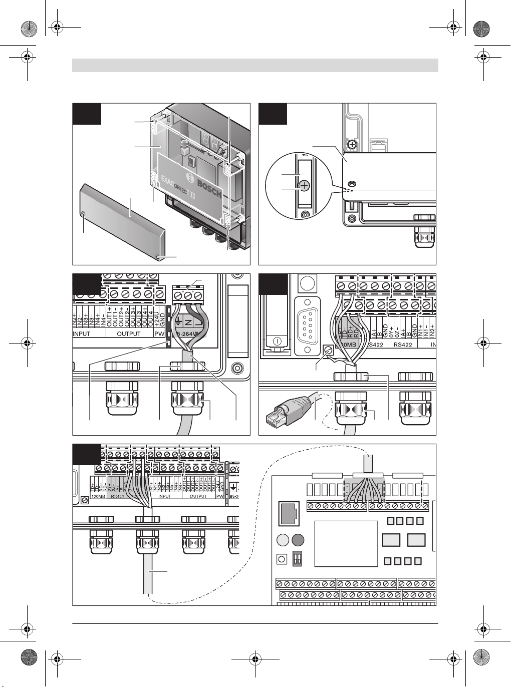
Anschlussarbeiten (siehe Bild A)
Der Anschluss der Basisstation
EXAConnecT und der externen Geräte
darf aufgrund der Komplexität der elektri-
schen Schaltungen nur von in der Elektro-/Informationstechnik geschultem Personal durchgeführt werden. An-
sonsten ist die Sicherheit der Bedienperson und der Geräte
nicht gewährleistet.
GEFAHR! Achten Sie darauf, dass die Basisstation und
das I/O-Module nicht an die Stromversorgung angeschlossen ist, bevor Sie sie öffnen. Die Basisstation
muss komplett spannungsfrei sein, da sonst die Gefahr eines elektrischen Schlages besteht.
Unter dem Wartungsdeckel 8 befindet sich die Klemmleiste
18 zum Anschluss der externen Module.
Es stehen Ihnen folgende Anschlüsse zur Verfügung:
– Netzwerkanschluss (Ethernet) „100MB“
– Serielle Schnittstelle „RS422“ (COM1)
– Serielle Schnittstelle „RS422“ (COM2)
– Serielle Schnittstelle „RS422“ (COM3)
– 24-V-Eingang „INPUT“ (4 Stück)
– 24-V-Ausgang „OUTPUT“ (4 Stück)
– Gleichstromausgang „PW“
Unter dem Servicedeckel 7 befinden sich zwei Dip-Schalter
16:
Schalter Beschreibung
1ONIP-Adresse im Setup EXAConnecT
1 OFF feste IP-Adresse: 10.10.10.10
2 Zur Zeit nicht belegt.
– Entfernen Sie an der spannungsfreien Basisstation den
Wartungsdeckel 8, indem Sie die unteren zwei kleinen
Kreuzschlitzschrauben 2 lösen.
– Entfernen Sie an der spannungsfreien Basisstation den
Servicedeckel 7, indem Sie die oberen vier kleinen Kreuzschlitzschrauben 2 lösen.
– Schrauben Sie nach Beendigung der Anschlussarbeiten
den Wartungsdeckel 8 oder den Servicedeckel 7 mit den
Kreuzschlitzschrauben 2 wieder fest an das Gehäuse der
Basisstation.
Achten Sie bei der Montage von Wartungs- und Servicedeckel
darauf, dass der Dichtungsring 36 korrekt in der Vertiefung
sitzt, da die Basisstation sonst nicht staub- und feuchteresistent ist.
Anschluss der Kabel an die Klemmleiste
Die Kabeldurchführungen sind geeignet für Kabel mit einem
Durchmesser von 5 –10 mm.
Achten Sie darauf, dass die Kabel korrekt in die Kabel-
durchführung eingelegt sind und die Dichtungen nicht
beschädigt sind. Ansonsten kann die Schutzart IP 54
nicht sichergestellt werden.
– Verschrauben Sie die Kabel der externen Module korrekt
und ziehen Sie die Schrauben mit 1,3 Nm an.
Wandbefestigung (siehe Bild B)
Zur Wandbefestigung der Basisstation benötigen Sie zwei
Kreuzschlitzschrauben 22 (M4 x 20; Kopfdurchmesser
8mm).
– Entfernen Sie den Wartungsdeckel 8 (siehe „Anschlussar-
beiten“, Seite 13).
– Führen Sie die Kreuzschlitzschrauben 22 in die Ausspa-
rung 9 am linken und rechten unteren Rand der Basisstation und schrauben Sie sie damit an die Wand.
– Befestigen Sie den Wartungsdeckel 8 wieder.
Anschluss der Basisstation an die Energieversorgung (siehe Bild C)
Spannung und Frequenz der Stromquelle müssen mit den Angaben auf dem Typenschild der Basisstation übereinstimmen.
Um die Basisstation an die Stromversorgung anzuschließen,
benötigen Sie ein 3-adriges geerdetes Netzkabel (Typ: Kupferschlauchleitung, min. 3 x 0,75 mm
Das Netzkabel muss mit einem Schutzkontaktstecker versehen sein und den länder- und kundenspezifischen Anforderungen entsprechen.
– Entfernen Sie den Wartungsdeckel 8 (siehe „Anschlussar-
beiten“, Seite 13).
Deutsch | 13
Werkseinstellung: 10.10.10.10
2
).
Bosch Power Tools 3 609 929 C48 | (9.10.13)

OBJ_BUCH-816-001.book Page 14 Wednesday, October 9, 2013 3:39 PM
14 | Deutsch
– Lösen Sie die Kontermutter 12 an der rechten Kabelver-
schraubung 11 durch Drehen gegen den Uhrzeigersinn.
– Ziehen Sie das steckerlose Kabelende des Netzkabels 23
durch die Öffnung der Kabelverschraubung, rechts entlang
des Isolierstegs 24 zum Anschluss 19.
– Schließen Sie die Phase am Symbol (Last), den Nulllei-
ter am Symbol (Neutral) und die Schutzerde am Symbol
des Anschlusses 19 an.
– Prüfen Sie, ob das Kabel fest sitzt. Drehen Sie dann die
Kontermutter 12 an der Kabelverschraubung 11 im Uhrzeigersinn wieder fest.
Achten Sie stets darauf, dass die Basisstation geerdet
ist.
Bei einem Steckanschluss stecken Sie den Schutzkontaktstecker des Netzkabels 23 in eine Schutzkontaktsteckdose in
Nähe der Basisstation.
Verwenden Sie kein Verlängerungskabel!
Wenn Sie die Basisstation direkt am Stromnetz anschließen
(Festanschluss), benötigen Sie ein zusätzliches Schaltelement, um die Basisstation bei Bedarf (z.B. Montage- oder
Wartungsarbeiten) stromlos zu schalten. Dieser Ein-/Ausschalter soll gut zugänglich in Nähe der Basisstation angebracht sein.
Anschluss der Basisstation an den PC
(siehe Bild D)
Sie können die Basisstation EXAConnecT sowohl direkt an Ihren PC anschließen, als auch an ein firmenspezifisches Netzwerk. Dafür benötigen Sie Netzwerkkabel mit einem RJ45Stecker.
– Entfernen Sie den Wartungsdeckel 8 (siehe „Anschlussar-
beiten“, Seite 13).
– Lösen Sie die Kontermutter 12 an der linken Kabelver-
schraubung 11 durch Drehen gegen den Uhrzeigersinn.
– Ziehen Sie das steckerlose K abelende des Netzwerkkabels
25 durch die Öffnung der Kabelverschraubung 12 zur
Klemmleiste 18.
– Messen Sie am 8-poligen Stecker, welche Farbe an wel-
chem Pin liegt.
Entnehmen Sie der Tabelle (siehe „Pin-Belegung der
Ethernet-Schnittstelle“, Seite14), welche Adern Sie für
den Anschluss an der Basisstation brauchen, und isolieren
Sie die nicht benötigten Adern ab.
– Schließen Sie die verbliebenen Adern gemäß der Tabelle
am Netzwerkanschluss „100MB“ der Klemmleiste 18 an.
– Schließen Sie die Abschirmung des Patch-Kab els an die Er-
dungsklemme 13 an.
Verwenden Sie die Crossover-Belegung für den direkten Anschluss der Basisstation an Ihren PC und die 1:1-V erbindung
zum Anschluss an Ihr Firmen-Netzwerk, Ihren Server oder Ihren Netzwerk-Hub.
– Prüfen Sie, ob das Kabel fest sitzt. Drehen Sie dann die
Kontermutter 12 an der Kabelverschraubung 11 im Uhrzeigersinn wieder fest.
3 609 929 C48 | (9.10.13) Bosch Power Tools
Pin-Belegung der Ethernet-Schnittstelle
Pin Farbe der Adern
z.B.
1weiß/orange RD+ TD+
2orange RD– TD–
3 weiß/grün TD+ RD+
4blau – –
5weiß/blau – –
6grün TD– RD–
7weiß/braun – –
8braun – –
CrossoverBelegung
1:1-Anschluss
am Netzwerk
Netzwerkanschluss der Basisstation
Bei der Installation müssen Sie die Netzwerkparameter für
die Verbindung der Basisstation mit Ihrem Rechner einstellen.
– Stecken Sie den Stecker des Kabels 25 in die Netzan-
schlussbuchse Ihres PCs, wenn Sie bei der Ethernet-Verbindung an der Basisstation die Crossover-Belegung gewählt haben.
Bei einem 1:1-Anschluss stecken Sie den Stecker in eine
freie Netzwerksteckdose Ihres Firmennetzwerks.
– Schließen Sie die Basisstation an die Energieversorgung
an (siehe „Anschluss der Basisstation an die Energieversorgung“, Seite 13).
– Stellen Sie die Netzwerkparameter ein (siehe „Einstellung
der Netzwerkparameter“, Seite 14).
Nach kurzer Zeit blinkt die gelbe LED-Anzeige 4 und auf dem
Display 6 erscheinen umlaufende Balken. Nach einigen Sekunden zeigt die grüne LED-Anzeige 3 durch Dauerlicht an,
dass die Basisstation betriebsbereit ist.
Einstellung der Netzwerkparameter
Die Basisstation wird mit der IP-Adresse 10.10.10.10 geliefert. Diese IP-Adresse sollte in Ihrem Netzwerk nicht mehr
verwendet werden.
Crossover-Belegung (Basisstation und Stand-Alone-PC)
Für den Datenaustausch zwi schen Ihrem PC und der Basisstation muss Ihr PC auf eine statische IP-Adresse eingestellt sein.
– Öffnen Sie in Ihrem Betriebssystem das Eigenschaften-
dialogfeld für Netzwerkverbindungen.
– Wählen Sie das Internet-Protokoll (TCP/IP) aus, das der
Netzwerkverbindung zur Basisstation zu Grunde liegt.
–Klicken Sie auf Eigenschaften.
– Aktivieren Sie die Option Folgende IP-Adresse verwen-
den.
– Geben Sie für die statische IP-A dresse folgende Einstellun-
gen in den Feldern ein:
IP-Adresse: 10.10.10.5
Subnetzmaske: 255.255.2 55.0
Ein einigen Fällen kann es nötig sein, die Basisstation zu routen.
– Starten Sie das Fenster Eingabeaufforderung.
– Geben Sie den Befehl
route add 10.10.10.10 10.10.10.5
ein und drücken Sie Enter.

OBJ_BUCH-816-001.book Page 15 Wednesday, October 9, 2013 3:39 PM
– Öffnen Sie auf Ihrem PC den Webbrowser und geben Sie
folgende Adresse ein:
http://10.10.10.10
Nach kurzer Zeit öffnet sich ein Sicherheitzertifikat, das Sie
bestätigen sollten, um alle Funktionen der Basisstation zur
Verfügung zu haben.
Das Java Applet wird geladen. Sie haben jetzt Zugriff auf die
Basisstation EXAConnecT.
Basisstation und Netzwerk
– Öffnen Sie einen Webbrowser und geben Sie in der
Adresszeile http://10.10.10.10 ein.
▷ Die Software wird geladen.
– Wählen Sie die Registerkarte EXAConnecT.
– Klicken Sie auf die Schaltfläche Setup.
▷ Das Fenster EXAConnecT Setup wird angezeigt.
– Wählen Sie die Registerkarte TCP/IP Settings.
▷ Die Option Get network parameters automatically
(DHCP) ist nicht ausgewählt.
– Geben Sie im Eingabefeld IP Address eine freie IP-Adresse
im gewünschten Adressbereich ein.
Der Standardwert 255.255.255.0 muss in der Regel nicht
geändert werden. Geben Sie bei Bedarf im Eingabefeld
Default Gateway die IP-Adresse des Gateways ein.
Hinweis: Notieren Sie die statische IP-Adresse auf dem
EXAConnecT oder in einem Verzeichnis.
Bei unbekannter IP-Adresse besteht die Möglichkeit die IPAdresse 10.10.10.10 mit Hilfe des DIP-Schalters 16 einzustellen (siehe „Anschlussarbeiten“, Seite 13).
– Klicken Sie auf die Schaltfläche Apply.
▷ Ein Hinweisfenster zum Neustart des Systems wird an-
gezeigt.
– Starten Sie das System neu (siehe „System neu starten
(Reset)“, Seite 19).
Betreiben Sie mehrere EXAConnecT müssen Sie zur eindeuti-
gen Identifikation verschiedene statische IP-Adressen oder
verschiedene Namen vergeben.
– Wählen Sie die Option Get network parame ters automa-
tically (DHCP) aus.
– Geben Sie im Eingabefeld einen Host-Namen an (Stan-
dardwert: XXXXXXXXX).
– Starten Sie das System neu (siehe „System neu starten
(Reset)“, Seite 19).
Sie können jetzt die Konfigurationsseite des EXAConnecT
durch die Eingabe des Host-Namens in der Adresszeile des
Webbrowsers öffnen.
Anschluss eines I/O-Modules
Das I/O-Module stellt 16 z usätzliche digitale Eingänge und 16
zusätzliche digitale Ausgänge zur Verfügung, die von der
Basisstation ausgewertet bzw. gesteuert werden können.
Energieversorgung
Die 24-V-Versorgung kann aus der Basisstation erfolgen (24V-Power-Ausgang der Basisstation: Klemmleiste 18), wobei
zu beachten ist, dass das I/O-Module dann auf dem gleichen
Massepotenzial wie die Basisstation liegt.
Sollen diese von einander getrennt sein, so ist ein zusätzliches externes Netzteil zur Versorgung des I/O-Modules vorzusehen. Die einzige Verbindung zur Basisstation ist dann die in
der Basisstation potenzialfrei ausgeführte RS422-Schnittstelle. Somit bleibt in diesem Fall die Trennung der Massepotenziale der Basisstation und des I/O-Modules erhalten.
Die RS422-Schnittstelle erlaubt lange Kabelverbindungen bis
zu 1000 m zwischen Basisstation und I/O-Module. Ab 20 m
Abstand zur Basisstation sollte das I/O-Module eine separate
Stromversorgung bekommen.
RS422-Verbindung zur Basisstation (siehe Bild E)
Der Anschluss des I/O-Modules an die Basisstation erfolgt
über eine RS422-Schnittstelle.
– Entfernen Sie den Wartungsdeckel 8 (siehe „Anschlussar-
beiten“, Seite 13).
– Lösen Sie die Kontermutter 12 an der mittleren linken Ka-
belverschraubung 11 durch Drehen gegen den Uhrzeigersinn.
– Ziehen Sie das steckerlose Kabelende eines 5-adrigen
Netzkabels 26 durch die Öffnung der Kabelverschraubung
12 zur Klemmleiste 18.
Die RS422-Schnittstellen sind entsprechend der nachfolgenden Tabelle zu verdrahten.
EXAConnecT I/O-Module
OY+ 1IA+
OZ– 1IB–
IA+ 1OY+
IB– 1OZ–
GND GND
– Prüfen Sie, ob das Kabel fest sitzt. Drehen Sie dann die
Kontermutter 12 an der Kabelverschraubung 11 im Uhrzeigersinn wieder fest.
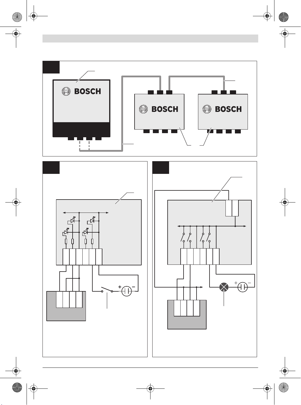
Kaskadierung (siehe Bild F)
Es können auch zwei I/O-Module’s kaskadiert werden, um die
Anzahl der verfügbaren Ein- und Ausgänge auf 32 zu erhöhen.
Dazu wird das zweite I/O-Module seinerseits an die freie
RS422-Schnittstelle des ersten I/O-Modules angeschlossen.
Ausgangsbefehle von der Basisstation für das 2. I/O-Module
werden vom 1. I/O-Module automatisch an das 2. I/O-Module
weitergeleitet. Ebenso werden Änderungen der Eingangszustände auf dem 2. I/O-Module vom 1. I/O-Module automatisch an die Basisstation weitergeleitet.
Die Eingänge und die Ausgänge verwenden das gleiche
Massepotenzial und sind nicht einzeln gegeneinander isoliert.
Auf der I/O-Leiste ist je zwei Eingangs- bzw. Ausgangsklemmen eine Masseklemme (GND) vorgesehen. Alle Masseklemmen auf sämtlichen Klemmleisten haben dasselbe Potenzial.
Deutsch | 15
Bosch Power Tools 3 609 929 C48 | (9.10.13)

OBJ_BUCH-816-001.book Page 16 Wednesday, October 9, 2013 3:39 PM
16 | Deutsch
Die RS422-Schnittstellen sind entsprechend der nachfolgenden Tabelle zu verdrahten.
1. I/O-Module 2. I/O-Module
2OY+ 1IA+
2OZ– 1IB–
2IA+ 1OY+
2IB– 1OZ–
GND GND
Beschaltung der digitalen Eingänge (siehe Bild G)
Die digitalen Eingänge sind im I/O-Module mit einer Schutzschaltung vor einem Optokoppler-Eingang (Diode) beschaltet.
Folgende Eingangspannungsbereiche sind zulässig:
– HIGH-Signal 3,2 – 26,0 V
–LOW-Signal 0,0–1,3V
Angeschaltet werden können passive (z.B. Taster oder Schalter) oder aktive Elemente (z.B. digitale SPS-Ausgänge).
Passive Elemente benötigen dafür jedoch eine zusätzliche
Spannungsquelle.
– Ein I/O-Module verbinden:
Wählen Sie im Dropdown Listenfeld Device on COM1 oder
im Dropdown Listenfeld Device on COM2 die Option I/O
Extensions (1x) aus.
Zwei I/O-Module verbinden:
Wählen Sie im Dropdown Listenfeld Device on COM1 oder
im Dropdown Listenfeld Device on COM2 die Option I/O
Extensions (2x) aus.
– Klicken Sie auf die Schaltfläche COM 1/2 Parameter Se-
tup.
▷ Das Fenster Setup COM1/2 wird angezeigt.
– Geben Sie in den Dropdown Listenfeldern folgende Optio-
nen ein:
Baudrate: 57600
Data Bits: 8
Parity: N
Stop Bits: 1
– Klicken Sie auf die Schaltfläche Save.
–Klicken Sie im Fenster EXAConnecT Setup auf die Schalt-
fläche
▷ Dadurch stehen bei allen angemeldeten Schraubern im
Man kann die notwendige Schaltspannung für einen Taster
oder Schalter auch von der Versorgung des I/O-Modules oder
der Basisstation entnehmen, da hier nur ein minimaler Strom
fließt.
Die Eingänge des I/O-Modules werden alle 50 ms gesampelt.
Angelegte Eingangssignale sollten eine Phasendauer von
100 ms daher nicht unterschreiten, um sicher erkannt zu
werden.
Beschaltung der digitalen Ausgänge (siehe Bild H)
Die digitalen Ausgänge des I/O-Modules sind elektronische
Leistungsschalter (Power MOSFET) mit geringem On-Widerstand (< 0,1 Ohm). Es wird kein Potenzial geliefert, sondern
nur nach Masse durchgeschaltet. Die Versorgung der zu
schaltenden Geräte ist daher durch externe Spannungen/Netzteile zu gewährleisten.
Die zulässigen Schaltbereiche sind:
– Maximale Schaltspannung 28 V
– Maximaler Schaltstrom 2A
Werden mit den Ausgängen des I/O-Modules digitale Eingän-
ge (mit hohem Innenwiderstand) anderer Geräte beschaltet
(z.B. von einer SPS), muss kein externes Netzteil verwendet
werden. Die Schaltspannung kann von der Versorgung des
I/O-Modules oder der Basisstation entnommen werden.
Bei Leistungsgeräten (z.B. Signallampen) sind externe Netzteile zwingend erforderlich, weil die Basisstation auf seinem
24-V-Ausgang nur maximal 420 mA liefern kann.
Konfiguration der Basisstation für das I/O-Module
– Öffnen Sie einen Webbrowser und geben Sie in der
Adresszeile http://10.10.10.10 ein.
▷ Die Software wird geladen.
– Wählen Sie die Registerkarte EXAConnecT.
– Klicken Sie auf die Schaltfläche Setup.
▷ Das Fenster EXAConnecT Setup wird angezeigt.
– Wählen Sie die Registerkarte COM Port Devices.
Die Bezeichnungen INn oderOUTn stellen die Ein- oder Ausgänge des oder der I/O-Modulee dar (n = Nummer des jeweiligen Ein-/Ausganges).
Anschluss des Freigabe-Tasters (siehe Bild I)
Wenn Sie einen BT-Schrauber mit einem Freigabe-Taster
sperren oder entsperren wollen (z. B. um eine Verschraubungsserie zu starten), müssen Sie einen Freigabe-Taster an
die Basisstation anschließen. Der Freigabe-Taster 39 kann
nur angeschlossen werden, wenn keine speicherprogrammierbare Steuerung (SPS) angeschlossen ist.
Die Spannung muss von einem positiven Eingang der Basisstation durch den Freigabe-Taster und zurück geführt werden.
– Entfernen Sie den Wartungsdeckel 8 (siehe „Anschlussar-
beiten“, Seite 13).
– Lösen Sie die Kontermutter 12 an der mittleren rechten
Kabelverschraubung 11 durch Drehen gegen den Uhrzeigersinn.
– Ziehen Sie das Kabelende des Kabels 40 durch die Öff-
nung der Kabelverschraubung 12 zur Klemmleiste 18.
– Schließen Sie eine Ader des Kabels 40 an der „+24V“-
Klemme des Gleichstromausgangs an und die andere Ader
an einer „IN+“-Klemme des 24-V-Eingangs. Sie können
„IN1+“, „IN2+“, „IN3+“ oder „IN4+“ wählen.
– Verbinden Sie anschließend in der Basisstation eine Ader
von der „GND“-Klemme des Gleichstromausgangs mit der
passenden „IN– “-Klemme des 24-V-Eingangs. Wenn Sie
z.B. eine Ader des Kabels 40 an der „IN1+“-Klemme des
24-V-Eingangs angeschlossen haben, müssen Sie die Ader
von der „GND“-Klemme an der„IN1–“-Klemme anschließen.
– Prüfen Sie, ob das Kabel fest sitzt. Drehen Sie dann die
Kontermutter 12 an der Kabelverschraubung 11 im Uhrzeigersinn wieder fest.
OK.
Fenster Screwdriver Setup die Registerkarten
Screwdriver Settings und Output Settings zur Verfügung, um weitere Ein- und Ausgänge einzustellen.
3 609 929 C48 | (9.10.13) Bosch Power Tools

OBJ_BUCH-816-001.book Page 17 Wednesday, October 9, 2013 3:39 PM
– Anschließend müssen Sie am Rechner das Sperren/Ent-
sperren per Freigabe-Taster für jeden einzelnen Schrauber
konfigurieren.
Hinweis: Die Ein- und Ausgänge können frei programmiert
werden (Informationen dazu siehe Software-Betriebsanleitung).
Anschluss eines Barcode-Scanners (siehe Bild J)
An der Basisstation können maximal zwei Barcode-Scanner
42 angeschlossen werden, z.B. um den BT-Schraubern unterschiedliche Schraubprogramme zuordnen zu können.
Die RS422-Schnittstellen sind potenzialfrei ausgeführt und
benötigen somit eine externe Spannungsversorgung.
RS422-Verbindung zur RS232- oder USB-Schnittstelle
Während die Basisstation zwei serielle Schnittstellen RS422
(COM1 und COM2) hat, verfügen einige Barcode-Scanner
über eine serielle RS232- oder USB-Schnittstelle. Ein solcher
Barcode-Scanner lässt sich daher nur mittels eines Schnittstellenwandlers an die Basisstation anschließen.
– Entfernen Sie den Wartungsdeckel 8 (siehe „Anschlussar-
beiten“, Seite 13).
– Lösen Sie die Kontermutter 12 an der mittleren linken Ka-
belverschraubung 11 und führen Sie ein mindestens 6-ad-
riges Netzkabel vom Schnittstellenwandler 41 durch die
Öffnung der Kabelverschraubung zu einer der beiden
RS422-Schnittstellen auf der Klemmleiste 18.
Die RS422-Schnittstellen sind entsprechend der nachfolgen-
den Tabelle zu verdrahten.
EXAConnecT Schnittstellenwandler
IA+ Tx+
IB– Tx–
OZ- Rx–
OY+ Rx+
GND GND
24V+ V+*
Sollte die Eingangsspannung des Schnittstellenwandlers 24-V-DC entsprechen, können Sie die 24V+ auf der Klemmle iste 18 des
EXAConnecT zur Spannungsversorgung verwenden.
Die empfohlenen Kabellängen betragen zwischen Basisstation und Schnittstellenwandl er maximal 1000 m und zwischen
Schnittstellenwandler und Barcode-Scanner maximal 5 m.
– Schrauben Sie nach Beendigung der Anschlussarbeiten
den Wartungsdeckel 8 mit den beiden Kreuzschlitzschrau-
ben 2 wieder fest an die Basisstation.
– Drehen Sie die Kontermutte r 12 an der mittleren linken Ka-
belverschraubung 11 wieder fest.
Hinweis: Bei der seriellen Technik werden D-SUB9-Stecker/Buchsen verwandt. Eventuell müssen Sie sogenannte
Gender Changer verwenden, die einen Wechsel von Stecker
auf Buchse oder umgekehrt ermöglichen.
Konfiguration des Barcode-Scanners
Nach abgeschlossener Verkabelung der Basisstation, Anschluss an die Energieversorgung und Verbindung mit dem
PC, müssen Sie die Software konfigurieren, damit die Eingangssignale des/der Schnittstellenwandler und des/der Barcode-Scanner verarbeitet werden können.
Hinweis: Halten Sie die Betriebsanleitungen des/der Schnittstellwandler und des/der Barcode-Scanner bereit. Dort finden Sie die nun notwendigen Einstellparameter.
– Öffnen Sie einen Webbrowser und geben Sie in der
Adresszeile http://10.10.10.10 ein.
▷ Die Software wird geladen.
– Wählen Sie die Registerkarte EXAConnecT.
– Klicken Sie auf die Schaltfläche Setup.
▷ Das Fenster EXAConnecT Setup wird angezeigt.
– Wählen Sie die Registerkarte COM Port Devices.
– Wählen Sie im Dropdown Listenfeld Device on COM1 die
Option Barcode Scanner aus.
– Klicken Sie auf die Schaltfläche COM1 Parameter Setup.
▷
– Geben Sie in den Dropdown Listenfeldern die gewünsch-
ten Optionen für Baudrate, Data Bits, Parity, Stop Bits
ein.
Die Baudrate der RS422-Schnittstellen an der Basisstati-
on kann im Bereich von 1 200 Baud bis 115200 Baud so-
wie mit verschiedenen Werten für die Datenbits, Parität
und Stoppbits per Software eingestellt werden. Ein Hard-
ware-Handshake ist per Definition nicht vorgesehen.
– Klicken Sie auf die Schaltfläche Save.
– Wenn Sie nur einen Barcode-Scanner angeschlossenen
haben, klicken Sie im Fenster EXAConnecT Setup auf die
Schaltfläche OK.
Wenn Sie einen zweiten oder dritten Barcode-Scanner ange-
schlossen haben, können Sie diesen mit den analogen Arbeitsschritten über das Dropdown Listenfeld Device on
COM2 oder Device on COM3 konfigurieren.
Anschluss einer Signallampe (siehe Bild K)
Sie können eine Signallampe 38 über die speicherprogrammierbare Steuerung (SPS) anschließen oder ohne SPS direkt
an der Basisstation.
Signallampen und Lampensäulen werden nicht von Bosch angeboten.
Beachten Sie deren Bedienungsanleitung.
Signallampen, die weniger als 10 W Gesamtleistung erfordern, können direkt an der Basisstation angeschlossen werden.
Ansonsten benötigen die Signallampen eine eigene Energieversorgung.
– Entfernen Sie den Wartungsdeckel 8 (siehe „Anschlussar-
beiten“, Seite 13).
– Lösen Sie die Kontermutter 12 an der mittleren rechten
Kabelverschraubung 11 und führen Sie die Kabel der Sig-
nallampen durch die Öffnung der Kabelverschraubung zu
den „OUT+“-Klemmen auf der Klemmleiste.
Der 24-V-Ausgang ist mit Optokopplern potenzialfrei für 24-
V-Signale ausgelegt. Es können bis zu 3 A geschaltet werden.
Deutsch | 17
Das Fenster Setup COM1 wird angezeigt.
Bosch Power Tools 3 609 929 C48 | (9.10.13)

OBJ_BUCH-816-001.book Page 18 Wednesday, October 9, 2013 3:39 PM
18 | Deutsch
– Schließen Sie die 4 Adern der Signallampen an den
„OUT+“-Klemmen an.
Es wird folgende Konfiguration empfohlen:
Klemme Beschreibung
OUT1+ Signalisiert „Schrauber ist freigegeben“ z. B.
für die gelbe Signallampe 43 am Ausgang
„OUT1“.
OUT2+ Signalisiert eine fehlerfreie Einzelverschrau-
bung (Einzelergebnis i.O.) z. B. für die grüne
Signallampe 45 am Ausgang „OUT2“.
OUT3+ Signalisiert eine fehlerhafte Einzelverschrau-
bung (Einzelergebnis n.i.O) oder eine fehlerhafte Schraubfallserie (Gesamtergebnis
n.i.O) z. B. für die rote Signallampe 46 am
Ausgang „OUT3“.
Die Einschaltdauer des Signals ist im Fenster
Screwdriver Setup, Registerkarte Output
Settings konfigurierbar.
OUT4+ Signalisiert eine fehlerfreie Schraubfallserie
(Gesamtergebnis i.O) z. B. für die blaue Signallampe 44 am Ausgang „OUT4“.
Die Einschaltdauer des Signals ist im Fenster
Screwdriver Setup, Registerkarte Output
Settings konfigurierbar.
Das Signal erlischt automatisch, sobald der
nächste Einzelschraubfall oder die nächste
Schraubfallserie beginnt.
– Führen Sie die 4 Adern der Signallampen zu einer externen
Energieversorgung 47 und von dieser zu den entsprechenden „24 V+“-Klemmen des „24 V– “-Ausgangs.
– Schrauben Sie nach Beendigung der Anschlussarbeiten
den Wartungsdeckel 8 mit den beiden Kreuzschlitzschrauben 2 wieder fest an die Basisstation.
– Drehen Sie die Kontermutter 12 an der mittleren rechten
Kabelverschraubung 11 wieder fest.
– Konfigurieren Sie die Signallampen wie eine standard SPS.
SPS-Anschluss
Die Basisstation besitzt 4 eingebaute 24-V-Ein- und Ausgänge, die mit Hilfe der Software unterschiedlich konfiguriert
werden können.
Bitte beachten Sie, dass die 24-V-Eingänge „IN n“ und die 24V-Ausgänge „OUT n“ nur Schaltelemente sind, die mit Optokopplern potenzialfrei für 24-V-Signale ausgelegt sind. Es
können bis zu 3 A geschaltet werden. Eine externe Strom-
versorgung ist für die SPS-Schaltfunktionen erforderlich.
– Entfernen Sie an der spannungsfreien Basisstation den
Wartungsdeckel 8, indem Sie die unteren zwei kleinen
Kreuzschlitzschrauben 2 herausdrehen (siehe Bild A).
So gelangen Sie an die Klemmleiste 18 (siehe Bild B).
– Lösen Sie die Kontermutter 12 an einer der mittleren Ka-
belverschraubung 11 und führen Sie die Kabel von und zur
SPS durch die Öffnung der Kabelverschraubung zum 24-VEingang oder zum 24-V-Ausgang je nach gewünschter
Schaltung, der nachfolgend aufgeführten Beispiele.
Beispiel 1: 2 Schrauber mit unterschiedlichen Signalen
(i.O./n. i.O.) oder 4 Schrauber mit einheitlichem Signal
(i.O.)
– Führen Sie ein Kabel vom positiven 24-V-Ausgang der SPS
entweder zur „OUT1+“- oder „OUT4+“-Klemme des 24-V-
Ausgangs der Basisstation und verkabeln Sie es in Reihe
über die „OUT+“-Klemmen.
– Führen Sie von jeder „OUT–“-Klemme ein Kabel zu einem
positiven Eingang an der SPS zurück.
Die Basisstation kann nun die Signale für zwei Schrauber mit
unterschiedlichen Signalen, wie folgt an die SPS übermitteln:
– „OUT1– “ meldet von Schrauber 0 das i.O.-Signal.
– „OUT2– “ meldet von Schrauber 0 das n.i. O.-Signal.
– „OUT3– “ meldet von Schrauber 1 das i.O.-Signal.
– „OUT4– “ meldet von Schrauber 1 das n.i. O.-Signal.
Bei 4 Schraubern mit gleichen Signalen, wenn beispi elsweise
nur die erfolgreichen Schraubaufgaben aufgezeichnet werden sollen, sieht die Übermittlung wie folgt aus:
– „OUT1– “ meldet von Schrauber 0 das i.O.-Signal.
– „OUT2– “ meldet von Schrauber 1 das i.O.-Signal.
– „OUT3– “ meldet von Schrauber 2 das i.O.-Signal.
– „OUT4– “ meldet von Schrauber 3 das i.O.-Signal.
Beispiel 2: 2 Schrauber mit unterschiedlichen Signalen
(i.O. und n. i.O) werden von der SPS auch freigegeben
– Führen Sie zwei Kabel von positiven 24-V-Ausgängen der
SPS zur „IN1+“- und „IN2+“-Klemme am 24-V-Eingang der
Basisstation.
– Führen Sie je ein Kabel von der „IN1– “-Klemme und der
„IN2–“-Klemme zu einem negativen Eingang der SPS.
Die SPS kann nun beispielsweise Schrauber 0 mit einem Sig-
nal zur „IN1+“-Klemme an der Basisstation freigeben.
Einstellung des DIP-Schalters (siehe Bild L)
– Entfernen Sie den Serviced eckel 7 (siehe „Anschlussarbei-
ten“, Seite 13).
So gelangen Sie an den DIP-Schalter 16.
Schalterbelegung
Schalter Beschreibung
1 ON Normaler Betrieb der Basisstation.
1 OFF Die Basisstation lässt sich fest auf die IP-
2 Zur Zeit nicht belegt.
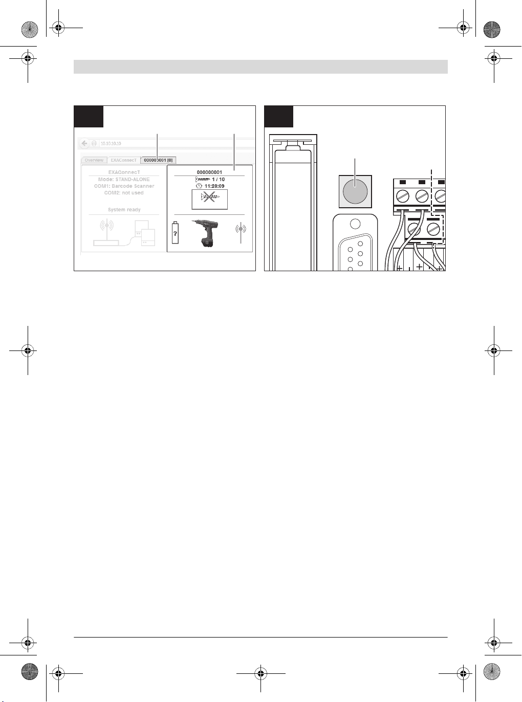
Wechsel der Pufferbatterie (siehe Bild M)
Die Pufferbatterie dient der Notstromversorgung der Basisstation, damit die gerade übermittelten Daten gespeichert
werden können.
Dies setzt voraus, dass eine leistungsstarke Pufferbatterie
eingesetzt ist und über das Service-Tool aktiviert wurde (siehe Anleitung Service-Tool).
Wenn die Pufferbatterie an Leistung verliert, erscheint im Display 6 der Basisstation der Statuscode EO (siehe „Status-
codes“, Seite 21).
Adresse 10.10.10.10 einstellen. Dies
empfiehlt sich, wenn Sie Wartungs- und
Service-Arbeiten vornehmen wollen.
3 609 929 C48 | (9.10.13) Bosch Power Tools

OBJ_BUCH-816-001.book Page 19 Wednesday, October 9, 2013 3:39 PM
Wechseln Sie noch während des Betriebs die Pufferbatterie,
da sonst ein Datenverlust droht.
– Entfernen Sie den Wartungsdeckel 8 (siehe „Anschlussar-
beiten“, Seite 13).
Berühren Sie keine spannungsführenden Teile der Ba-
sisstation, wenn Sie während des Betriebs den Serviceoder Wartungsdeckel entfernt haben. Es besteht die
Gefahr eines elektrischen Schlags.
–Entfernen Sie die alte Batterie 15 und setzen Sie eine neue
1,5 V Standard-Mikrozelle AAA ein.
Achten Sie beim Einsetzen der Batterie auf die richtige Polung entsprechend der Abbildung.
Wechsel der Knopfzelle für die Echtzeituhr (siehe
Bild N)
Eine Lithiumbatterie (3 V, CR 2032) dient der permanenten
Stromversorgung der Echtzeituhr (Real Time Clock, RTC).
– Trennen Sie die Basisstation von der Stromversorgung.
– Entfernen Sie den Serviced eckel 7 (siehe „Anschlussarbei-
ten“, Seite 13).
– Biegen Sie den Halteb ügel zur Seite und entnehmen Sie
die verbrauchte Knopfzelle 20 aus dem Sockel 21.
– Stecken Sie unter Beachtung der richtigen Polung eine
neue Knopfzelle in den Sockel 21, bis der Haltebügel über
den Seitenrand der Knopfzelle klickt.
– Schrauben Sie den Servicedeckel 7 mit den Kreuzschlitz-
schrauben 2 wieder fest an das Gehäuse der Basisstation.
– Verbinden Sie die Basisstation mit der Stromversorgung.
– Wählen Sie in der Konfigurationssoftware die Registerkar-
te EXAConnecT.
– Klicken Sie auf die Schaltfläche Setup.
▷ Das Fenster EXAConnecT Setup wird angezeigt.
– Wählen Sie die Registerkarte Access Point Parameter.
– Geben Sie im Feld Clock Time Adjustment das aktuelle
Datum und die aktuelle Uhrzeit ein oder wählen Sie die Op-
tion Taking over Date/Time from PC.
–Klicken Sie im Fenster EXAConnecT Setup auf die Schalt-
fläche OK.
Betrieb
Inbetriebnahme der Basisstation
Lesen und beachten Sie die Betriebsanleitungen der In-
dustrie-Akkuschrauber (BT-EXACT/BT-
ANGLE EXACT). Bevor Sie Verschraubungen an der Basis-
station protokollieren können, muss ein geladener Akku in
den entsprechenden Schrauber gesteckt werden.
Durch einmaliges Drücken des Drückerstarts geht der
Schrauber in den Bereitschaftsmodus. Dies wird durch die
rot blinkende BT-LED am Schrauber angezeigt.
– Öffnen Sie einen Webbrowser und geben Sie in der
Adresszeile http://10.10.10.10 ein.
▷ Die Software wird geladen.
– Bestätigen Sie gegebenenfalls das Sicherheitszertifikat.
– Wählen Sie die Registerkarte EXAConnecT.
– Klicken Sie auf die Schaltfläche Setup.
▷ Das Fenster EXAConnecT Setup wird angezeigt.
– Wählen Sie die Registerkarte Screwdrivers, um zum An-
meldemenü zu gelangen.
– Klicken Sie auf die Schaltfläche Search.
▷ Alle im Bereitschaftsmodus befindlichen Schrauber
– Wählen Sie den Schrauber aus, den Sie anmelden wollen
und klicken Sie danach auf die Schaltfläche Connect.
▷ Der Schrauber wird auf der rechten Seite angezeigt.
–Klicken Sie im Fenster EXAConnecT Setup auf die Schalt-
fläche OK.
▷ Am Schrauber wird die Verbindung mit der dauerhaft
– Wählen Sie die Registerkarte Overview.
▷ Der Schrauber wird in einem rechteckigen Symbolfeld
▷ Für jeden angemeldeten Schrauber wird zusätzlich eine
– Klicken Sie auf das Schraubersymbol im Symbolfeld oder
auf die Schaltfläche Unlock in der zugehörigen SchrauberRegisterkarte.
▷ Der Schrauber ist für die eingestellte Schraubaufgabe
Nach erfolgreichem Abschluss der Schraubaufgabe (Standardwert 5 x i.O.) ist der Schrauber wieder automatisch gesperrt. Näheres dazu finden Sie in der Bedienungsanleitung
der Software.
LED-Anzeigen Basisstation
Unterhalb des Displays 6 zur Anzeige der Statuscodes, befinden sich drei LED-Anzeigen, die den Systemzustand signalisieren.
Nr.
3 grün Dauerlicht Basisstation betriebsbereit
4 gelb unregelmäßi-
5 blau Dauerlicht mindestens eine bestehen-
System neu starten (Reset) (siehe Bild P)
1. Möglichkeit:
– Unterbrechen Sie die Energieversorgung.
Hinweis: Bei nicht aktiver Notstromversorgung (werksei-
2. Möglichkeit:
– „Reset“ über Service-Tool (siehe Anleitung Service-Tool).
3. Möglichkeit:
– Entfernen Sie den Wartungsdeckel 8 (siehe „Anschlussar-
beiten“, Seite 13).
– Drücken Sie mindestens 3 Sekunden auf den Reset-Taster
17.
Deutsch | 19
(max. 25) werden auf der linken Seite angezeigt. Dies
kann bis zu 30 Sekunden dauern.
leuchtenden BT-LED angezeigt.
Der Schrauber ist nun gesperrt.
angezeigt (siehe Bild O).
Registerkarte Seriennummer [Schrauberindex (0-6)]
(z. B. 0000001 [0]) angezeigt (siehe Bild O).
freigeschaltet.
Die rote BT-LED erlischt und der Schrauber kann verwendet werden.
LED-Anzeige
tig aus) gehen alle Schraubdaten verloren. Bitte vorher
speichern.
Bedeutung
Ethernet-Verbindung
ges Blinken
de Bluetooth-Verbindung
Bosch Power Tools 3 609 929 C48 | (9.10.13)

OBJ_BUCH-816-001.book Page 20 Wednesday, October 9, 2013 3:39 PM
20 | Deutsch
Sobald die LED-Anzeigen erlöschen, bootet das System neu
(ca. 20 Sekunden).
Hinweis: Während des Boot-Vorgangs darf kein weiterer
„Reset“ erfolgen. Das Betriebssystem könnte Schaden nehmen.
Inbetriebnahme des I/O-Modules
Wird das I/O-Module über den Access Point mit 24 V versorgt,
so schaltet es sich beim Einschalten des Access Points automatisch mit ein.
Bei Versorgung des I/O-Modules durch ein externes Netzteil
sollte dieses vor dem Access Point oder zumindest gleichzeitig wie der Access Point eingeschaltet werden, weil letzterer
beim Hochfahren dem I/O-Module Initial-Kommandos senden
können muss.
LED-Anzeigen I/O-Module
Unterhalb des Displays 6 zur Anzeige der Statuscodes, befinden sich zwei LED-Anzeigen, die den Systemzustand signalisieren.
Nr. LED-Anzeige Bedeutung
32 grün Dauerlicht I/O-Module be-
31 rot Kommunikationsfehler
– falsche Verkabelung der RS422-
Schnittstelle
– falsche Konfiguration der Baudra-
te im Setup der Basisstation
– nicht zueinander passende Firm-
ware von Basisstation und I/O-Module
triebsbereit
BT-EXACT/BT-ANGLE EXACT Schraubsystem
Das Schraubsystem BT-EXACT/BT-ANGLE EXACT ermöglicht
eine kabellose Datenübertragung von Schraubsignalen mit
Bluetooth wireless technology.
Gesendet werden i.O.- und n.i.O.-Signale (Verschraubung in
Ordnung/nicht in Ordnung) der Industrie- Akkuschrauber d er
Serie BT-EXACT und BTANGLE EXACT an die Basisstation.
Ohne die Basisstation ist die Inbetriebnahme von Schraubern
der Reihe BT-EXACT und BT-ANGLE EXACT nicht möglich: Die
Schrauber sind bei Lieferung gesperrt und können nur von
der Basisstation freigegeben werden.
– Nehmen Sie zuerst die Basisstation in Betrieb.
3 609 929 C48 | (9.10.13) Bosch Power Tools

OBJ_BUCH-816-001.book Page 21 Wednesday, October 9, 2013 3:39 PM
Statuscodes
Alle Statuscodes werden sowohl im Display 6 der Basisstation als auch im Monitorprogramm angezeigt.
Fehlercodes, die sich auf einen Ausfall oder Nicht-Erreichbarkeit der Basisstation beziehen, werden nur im Monitorprogramm angezeigt.
Warnungen
Warnungen dienen der Information.
Es sind Meldungen, die darauf hindeuten, dass eine Fehlersi-
tuation eintreten könnte, wenn nicht rechtzeitig Gegenmaßnahmen vorgenommen werden.
Code Fehlerbeschreibung Abhilfe
A<N> Der Absolutzählerwert N_OFF im Schrauber hat den Wert 1000 er-
reicht bzw. unterschritten. Bei N_OFF = 0 schaltet der Schrauber
endgültig ab.
H0 Der Speicher der Basisstation ist aufgrund sich ansammelnder Ist-
Daten zu 50 % verbraucht.
H1 Der Speicher der Basisstation ist aufgrund sich ansammelnder Ist-
Daten zu 75 % verbraucht.
H2 Der Speicher der Basisstation ist aufgrund sich ansammelnder Ist-
Daten zu 90 % verbraucht.
Liegen mehrere Statuscodes gleichzeitig an, werden diese im
zyklischen Wechsel (alle 2 Sekunden) angezeigt.
Die Statuscodes unterteilen sich in folgende Gruppen:
– Warnungen
– Nicht kritische Fehler
– Kritische Fehler
– Protokollspezifische Fehler
Der Betrieb der Basisstation ist zunächst nicht eingeschränkt.
Parameter N_OFF des betreffenden Schraubers
wieder auf einen größeren Wert setzen (Schrauber
Setup: Service und Kalibrierung).
Daten zum nächstmöglichen Zeitpunkt über das
Monitorprogramm sichern.
Daten schnellstmöglich über das Monitorprogramm
sichern.
Daten sofort über das Monitorprogramm sichern.
Deutsch | 21
Nicht-kritische Fehler
Die Anzeige von nicht-kritischen Fehlern dienen der Information.
Der Betrieb der Basisstation ist nur noch eingeschränkt möglich.
Nicht-kritische Fehler können von der Basisstation in der Regel selbst behoben werden. Falls nicht, werden sie zu kritischen Fehlern konvertiert.
Code Fehlerbeschreibung Abhilfe
C<N> Der Schrauber mit dem internen Index N ist außer Funkreichweite
oder stromlos (Akkuwechsel). Solange der Statuscode sichtbar
Schrauber wieder in Funkreichweite bringen bzw.
vollen Akku einsetzen.
ist, versucht die Basisstation zyklisch, den Schrauber wieder zu
verbinden.
Die primäre Spannungsversorgung ist ausgefallen oder der ResetTaster wurde betätigt.
Primäre Stromversorgung der Basisstation über-
prüfen.
Die Basisstation sichert alle Daten, wenn die Notstromversorgung
aktiviert wurde (siehe Anleitung Service-Tool).
Alle Schrauber werden gesperrt. Alle sonstigen Schnittstellen wer-
den abgeschaltet.
Nach Ende der Datensicherung schaltet sich die Basisstation ganz
ab bzw. startet erneut.
L0 Die Basisstation schickt keine zyklischen Keep-Alive-Pakete mehr
Ethernet-Kabel vom PC zur Basisstation prüfen.
oder die TCP-Verbindung zur Basisstation wurde unerwartet getrennt (RESET).
Hinweis: Diese Meldung wird nur im Monitorprogramm angezeigt.
L1 Bei der automatischen Datensicherung per FTP ist ein Fehler auf-
getreten. Im Falle einer temporären Störung (Datensicherung
funktioniert beim nächsten Zyklus wieder) wird der Status-Code
automatisch gelöscht.
Bosch Power Tools 3 609 929 C48 | (9.10.13)
Ethernet-Kabel, FTP-Einstellungen im AP-Setup
und entfernten FTP-Server überprüfen.
Bei dauerhaftem bzw. wiederholtem Auftreten Her-
steller kontaktieren.

OBJ_BUCH-816-001.book Page 22 Wednesday, October 9, 2013 3:39 PM
22 | Deutsch
Kritische Fehler
Bei kritischen Fehlern ist in der Regel der Einsatz eines Service-Technikers notwendig.
Der Betrieb der Basisstation ist nur noch eingeschränkt bzw.
gar nicht mehr möglich.
Code Fehlerbeschreibung Abhilfe
F0 Der Speicher der Basisstation is t aufgrund sich ansammelnder Ist-
Daten zu 100 % verbraucht.
Die Basisstation ist mit Hilfe eines Reserve-Speichers noch be-
Daten müssen über das Monitorprogramm gesi-
chert werden, bevor der Normalbetrieb wieder auf-
genommen werden kann.
triebsbereit, jedoch werden neue Soll- oder Ist-Daten nicht mehr
gespeichert.
Alle Schrauber sind gesperrt.
F1 Die Einstellungen der Basisstation konnten aufgrund eines inter-
nen Speicherfehlers nicht gespeichert werden.
F2 Die Einstellungen der Schrauber konnten aufgrund eines internen
Speicherfehlers nicht gespeichert werden.
F3 Die Einstellungen der Basisstation konnten aufgrund eines fal-
schen Dateiformats oder einer falschen Dateiversion nicht gelesen
werden.
Hinweis: Die Basisstation ist mit den Standard-Einstellungen be-
Speichern erneut versuchen, sonst Hersteller kon-
taktieren.
Speichern erneut versuchen, sonst Hersteller kon-
taktieren.
Einstellungen der Basisstation erneut eingeben und
sichern.
Bei wiederholtem Auftreten Hersteller kontaktie-
ren.
triebsbereit.
F4 Die Einstellungen der Schrauber konnten aufgrund eines falsc hen
Dateiformats oder einer falschen Dateiversion nicht gelesen werden.
Hinweis: Die Basisstation ist mit den Standard-Einstellungen be-
Schrauber erneut registrieren bzw. Schrauber-Ein-
stellungen erneut eingeben und sichern.
Bei wiederholtem Auftreten Hersteller kontaktie-
ren.
triebsbereit. Vorher bereits registrierte Schrau ber müssen jedoch
neu registriert werden.
E0 Die Batterieüberw achung hat eine zu geringe Kapazität der Puffer-
Batterie festgestellt. Bei Stromausfall droht Datenverlust, falls die
Pufferbatterie wechseln (siehe „Wechsel der Puf-
ferbatterie“, Seite 18).
Basisstation noch ungesicherte Daten im Speicher hat.
Hinweis: Falls ein Datenverlust beim Abschalten der primären
Stromversorgung droht, ist die Batterie unbedingt im laufenden
Betrieb zu wechseln.
E1 Die interne Real-Time-Clock (RTC) ist noch nicht gestellt worden.
Uhrzeit stellen.
Eine Erzeugung von Zeitstempeln ist nicht möglich.
Alle Schrauber sind gesperrt.
E2 Die Basisstation hat derzeit ein Datum vor dem 1. September
Uhrzeit stellen.
2004. Eine Erzeugung von aktuellen Zeitstempeln ist nicht möglich.
Alle Schrauber sind gesperrt.
E3 Die Basisstation hat aufgrund eines vorherigen Stromausfalls auf
Batteriebetrieb (Backup-Power) umgeschaltet, jedoch wegen zu
Pufferbatterie wechseln (siehe „Wechsel der Puf-
ferbatterie“, Seite 18).
geringer Batteriekapazität nicht mehr alle Daten sichern können.
Hinweis: Diese Meldung wird automatisch gelöscht, sobald wieder Ist-Daten erzeugt werde n.
3 609 929 C48 | (9.10.13) Bosch Power Tools

OBJ_BUCH-816-001.book Page 23 Wednesday, October 9, 2013 3:39 PM
Code Fehlerbeschreibung Abhilfe
E4 Die Betriebssoftware (Firmware) der Basisstation ist nicht vorha n-
den (Datei PROEJCT.HEN auf der Flash-Disk). Sofern die Basisstation noch betriebsbereit ist, gibt es für den laufenden Betrieb keine Einschränkung (Betriebsbereitschaft wird durch grüne LED
angezeigt). Allerdings wird die Basisstation in diesem Zustand
nach dem nächsten Reset nicht mehr hochfahren.
Sofern beim Hochfahren der Basisstation (nach einem Reset) festgestellt wird, dass die Betriebssoftware fehlt, wird derselbe Fehler-Code angezeigt, aber ohne Betriebsbereitschaft (grüne LED
leuchtet nicht). Ein normaler Betrieb der Basisstation ist in diesem
Zustand nicht möglich.
E5 Ein Routine-Check des Dateisystems beim Start der Basisstation
hat eine Inkonsistenz im Flashspeicher festgestellt. Es läuft lediglich ein Reservesystem, um diese Meldung anzuzeigen und Gegenmaßnahmen einzuleiten.
Ein normaler Betrieb der Basisstation ist nicht möglich.
Hinweis: Alle gespeicherten Daten (inklusive der Firmware) sind
gelöscht.
E6 Die Bluetooth-Schnittstelle der Basisstation ist nicht oder nicht
mehr verfügbar oder der Bluetooth-Protokoll-Stack meldet unerwartete Fehler.
E7 Die Betriebs-Software der Basisstation hatte einen internen Aus-
nahmefehler (Exception).
E8 Falsche Firmware Version:
Die Betriebssoftware (Firmware) des Access Points hat eine falsche Version (z. B. V1.9.x auf einem EXAConnecT II).
P<N> Der Schrauber mit dem internen Index N hat über die BT-Schnitt-
stelle mit falschem Format oder gar nicht geantwortet.
Protokollspezifische Fehler
Protokollspezifische Fehler beziehen sich auf das jeweilige
Datenbank-Protokoll wobei die Fehler-Codes individuell an
dieses angepasst werden können.
Diese Fehlercodes können je nach Protokoll unterschiedliche
Bedeutungen haben.
Wartung und Service
Wartung und Reinigung
Trennen Sie die Basisstation sowohl von der Energie-
versorgung als auch vom PC, wenn Sie Reinigungsarbeiten durchführen. Dadurch vermeiden Sie die Gefahr
eines elektrischen Schlages.
Kontrollieren Sie beim Entfernen von Service- und
Wartungsdeckel den Dichtungsring 36 auf korrekten
Sitz. Tauschen Sie einen schadhaften Dichtungsring
aus. Nur ein korrekt in der Vertiefung sitzender Dichtungs-
ring garantiert bei geschlossenem Gehäuse Staub- und
Feuchteresistenz.
Reinigen Sie die Anschlussbuchsen und das Gehäuse der von
der Energieversorgung getrennten Basisstation mit einem
Firmware-Update durchführen bzw. Basisstation
flashen, wenn nicht mehr betriebsbereit.
Flash-Speicher neu formatieren.
Bei wiederholtem Auftreten Hersteller kontaktie-
ren.
Basisstation neu starten.
Bei wiederholtem Auftreten Hersteller kontaktie-
ren.
Basisstation neu starten.
Bei wiederholtem Auftreten Hersteller kontaktie-
ren.
Richtige Firmware (V2.x) auf Access Point aufspie-
len (flashen).
Schrauber-Akku oder Schrauber austauschen.
Bei wiederholtem Auftreten Hersteller kontaktie-
ren.
trockenen, fusselfreien Tuch und entfernen Sie Staub- und
Schmutzpartikel.
Lassen Sie Wartungs- und Reparaturarbeiten nur von
qualifiziertem Fachpersonal durchführen. Damit wir d
sichergestellt, dass die Sicherheit der Basisstation und
des I/O-Modules erhalten bleibt.
Eine autorisierte Bosch-Kundendienststelle führt diese Arbeiten schnell und zuverlässig aus.
Zubehör
Über das komplette Qualitätszubehörprogramm können Sie
sich im Internet unter www.bosch-pt.com oder bei Ihrem
Fachhändler informieren.
Kundendienst und Anwendungsberatung
Geben Sie bei allen Rückfragen und Ersatzteilbestellungen
bitte unbedingt die 10-stellige Sachnummer laut Typenschild
des Produkts an.
Der Kundendienst beantwortet Ihre Fragen zu Reparatur und
Wartung Ihres Produkts sowie zu Ersatzteilen. Explosionszeichnungen und Informationen zu Ersatzteilen finden Sie
auch unter:
www.bosch-pt.com
Deutsch | 23
Bosch Power Tools 3 609 929 C48 | (9.10.13)

OBJ_BUCH-816-001.book Page 24 Wednesday, October 9, 2013 3:39 PM
24 | Deutsch
Das Bosch-Anwendungsberatungs-Team hilft Ihnen gerne bei
Fragen zu unseren Produkten und deren Zubehör.
www.powertool-portal.de, das Internetportal für Handwerker und Heimwerker.
Deutschland
Robert Bosch GmbH
Servicezentrum Elektrowerkzeuge
Zur Luhne 2
37589 Kalefeld – Willershausen
Unter www.bosch-pt.com können Sie online Ersatzteile bestellen oder Reparaturen anmelden.
Kundendienst: Tel.: (0711) 40040480
Fax: (0711) 40040481
E-Mail: Servicezentrum.Elektrowerkzeuge@de.bosch.com
Anwendungsberatung: Tel.: (0711) 40040480
Fax: (0711) 40040482
E-Mail: Anwendungsberatung.pt@de.bosch.com
Österreich
Tel.: (01) 797222010
Fax: (01) 797222011
E-Mail: service.elektrowerkzeuge@at.bosch.com
Schweiz
Tel.: (044) 8471511
Fax: (044) 8471551
E-Mail: Aftersales.Service@de.bosch.com
Luxemburg
Tel.: +32 2 588 0589
Fax: +32 2 588 0595
E-Mail: outillage.gereedschap@be.bosch.com
Entsorgung
Basisstation, I/O-Module, Batterien, Zubehör und
Verpackungen sollen einer umweltgerechten Wiederverwertung zugeführt werden.
Werfen Sie elektronische Bauteile und Batterien nicht in den
Hausmüll!
Nur für EU-Länder:
Gemäß der Europäischen Richtlinie 2012/19/EU
über Elektro- und Elektronik-Altgeräte und ihrer
Umsetzung in nationales Recht müssen nicht
mehr gebrauchsfähige Elektro- und Elektronikgeräte getrennt gesammelt und einer umweltgerechten Wiederverwertung zugeführt werden.
Nicht mehr gebrauchsfähige Akkus/Batterien können direkt
abgegeben werden bei:
Deutschland
Recyclingzentrum Elektrowerkzeuge
Osteroder Landstraße 3
37589 Kalefeld
Schweiz
Batrec AG
3752 Wimmis BE
Änderungen vorbehalten.
3 609 929 C48 | (9.10.13) Bosch Power Tools

OBJ_BUCH-816-001.book Page 25 Wednesday, October 9, 2013 3:39 PM
Safety warnings for access points and expansion
English
Safety Notes
General Safety Rules
WARNING
and instructions may result in electric shock, fire and/or serious injury.
Save all warnings and instructions for future reference.
The term “power tool” in the warnings refers to your mainsoperated (corded) power tool or battery-opera ted (cordless)
power tool.
Workplace safety
Keep work are clean and lit. Cluttered and dark areas in-
vite accidents.
Do not use the screwdriving system consisting of
EXAConnecT access point, I/O module and BT-EXACT/BT-ANGLE EXACT production cordless screwdrivers in an explosion-hazardous environment in which
flammable liquids, gases or dusts are present. Power
tools create sparks which may ignite the dust or fumes.
Electrical Safety
Avoid body contact with earthed or grounded surfaces
such as pipes, radiators, ranges and refrigerators.
There is an increased risk of electric shock if your body is
earthed or grounded.
Do not abuse the cord. Never use the cord for carrying,
pulling or unplugging the access point, the I/O module
or the power tool. Keep cord away from heat, oil, sharp
edges and moving parts. Damaged or entangled cord s in-
crease the risk of electric shock.
Personal safety
Stay alert, watch what you are doing and use common
sense when operating a screwdriving system. Do not
use a screwdriving system while you are tired or under
the influence of drugs, alcohol or medication. A mo-
ment of inattention while operating the screwdriving system may result in serious personal injury.
Screwdriving system use and care
Store idle screwdriving systems out of the reach of
children and do not allow persons unfamiliar with the
screwdriving system or these instructions to operate
the screwdriving system. Screwdriving systems are dan-
gerous in the hands of untrained users.
Use the screwdriving system, acc essories and tool bits
etc. in accordance with these instructions, taking into
account the working conditions and the work to be performed. Use of the screwdriving system for operations
different from those intended could result in a hazardous
situation.
Read all safety warnings and all instructions. Failure to follow the warnings
modules
DANGER! Ensure that the access point and the I/O mod-
ule are not connected to the power supply before you
open them. The access point must be completely de-ener-
gised, otherwise there is a risk of electric shock.
Do not expose the access point and the I/O module to
rain or wet conditions. Rain or water entering the access
point or the I/O module will increase the risk of electric
shock.
Keep the access point and the I/O module clean. Dirt
poses a danger of electric shock.
Check the access point, I/O module, cables and plugs
before each use. Stop using the access point and the
I/O module as soon as you discover damage to them.
Have them serviced only by a qualified repair person
using only identical replacement parts. Damaged ac-
cess points, I/O modules, cables and plugs increase the
risk of electric shock.
Due to the complexity of the electrical circuitry, the
EXAConnecT access point and the external devices
(Personal Computer, I/O module, signal lamp, scanner,
etc.) must be connected only by personnel trained in
electrical engineering and information technology.
Otherwise the safety of the user and the devices is not ensured.
Read and strictly observe the safety and work instruc-
tions in the operating instructions of the
BT-EXACT/BT-ANGLE EXACT screwdrivers you are using.
Product Description and Specifications
Intended Use
The Bosch BT-EXACT/BT-ANGLE EXACT and EXAConnecT
screwdriving system is intended for driving and loosening
screws and tightening and loosening nuts in the specified dimension and performance range. It is not intended for documenting the torque or rotation angle of a screw connection.
The OK or NOK signal results exclusively from a sh ut-off signal
of the mechanical shut-off clutch, which has to be correspondingly calibrated and which requires continual re-checking. This OK or NOK signal does not permit any conclusions to
be drawn about the quality of a screw connection.
These signals can be analysed and documented using the
EXAConnecT access point and its software. Any mo dification
of the hardware and/or software or the connection of additional hardware fundamentally exclud es any liability of Robert
Bosch GmbH.
English | 25
Read all safety warnings and all instructions. Failure to follow the warnings and in-
structions may result in electric shock, fire
and/or serious injury.
Bosch Power Tools 3 609 929 C48 | (9.10.13)

OBJ_BUCH-816-001.book Page 26 Wednesday, October 9, 2013 3:39 PM
26 | English
Country-specific instructions
European Union
This screwdriving system may be used in all countries of the
European Union. In France, the use of Bluetooth is only tolerate d. P leas e in form you rsel f of the regulations of the region of
use.
North America
The access point has been tested and found to comply with
the limits for a Class A digital device, pursuant to Part 15 of
the FCC Rules (Federal Communications Commission). These
limits are designed to provide reasonable protection against
harmful interference when the access point is operated in a
commercial environment. This access point generates, uses,
and can radiate radio frequency energy and, if not installed
and used in accordance with the manufacturer’s instruction
manual, may cause interference to radio communications.
Operation of this access point in a residential area is likely to
cause harmful interference, in which case the user will be required to correct the interference at his own expense.
Product Features
The numbering of the product features refers to the illustrations on the graphics pages.
1 EXAConnecT access point
2 Phillips screw s
3 Green LED indicator (ready for operation)
4 Yellow LED indicator (Ethernet connection)
5 Blue LED indicator (Bluetooth connection)
6 Display: Display for status codes
7 Service cover plate
27 I/O module expansion module
28 Phillips screws
29 DIP switch for I/O module
30 Reset button for I/O module
31 Red LED indicator (error)
32 Green LED indicator (ready for operation)
33 RJ45 interface (Ethernet)
34 Cable gland (PG 16)
35 Service cover plate
36 Seal ring
Optional system expansions
37 Mechanical button/switch
38 Signal lamp
39 Release button *
40 Cable of the release button
41 Interface converter
42 Barcode scanner (RS232 or USB)
43 Yellow signal lamp
44 Blue signal lamp
45 Green signal lamp
46 Red signal lamp
47 External power supply of the signal lamp
Configuration software
48 Symbol field for screwdriver
49 Screwdriver serial number tab
*Accessories shown or described are not part of the standard delivery scope of the product. A complete overview of accessories
can be found in our accessories program.
8 Maintenance cover plate
9 Holes for wall fastening
10 Seal ring
11 Cable gland (PG 16)
12 Locknut for cable gland
13 Ground terminal
14 RS232 interface
15 Backup battery
16 DIP switch for access point
17 Reset button for access point
18 Terminal strip
19 Power supply connection
20 Button cell for real time clock
21 Button cell socket
22 M4 Phillips screws
23 Mains cable (3-wire) *
24 Plastic bar for insulating the power supply connection
from the other connections
25 Network cable (Ethe rnet)*
26 Mains cable (5-wire) *
3 609 929 C48 | (9.10.13) Bosch Power Tools

OBJ_BUCH-816-001.book Page 27 Wednesday, October 9, 2013 3:39 PM
English | 27
Technical Data
EXAConnecT access point I/O module expansion module
Article number
Input voltage
Maximum input current
Input frequency
Direct current output
V 100–240 24
mA 150 200
Hz 50–60
V
– Output voltage
– Maximum output current
mA
Storage temperature °C -20 ... 80 -20 ... 80
Operating temperature
°C 5–70 5–70
Relative humidity
%
Data interface Bluetooth wireless technology class 2
Maximum transmission range
Backup batteries
m10.0* –
1.5 V (Standard microcell AAA)
(3 V lithium battery, CR 2032)
Weight according to EPTA-Procedure
01/2003
kg 1.0 0.5
Protection class
Degree of protection
Bluetooth® is a registered trademark of Bluetooth SIG, Inc. (Special Interest Group).
The values given are valid for a nominal voltage [U] of 230 V. For different vol tages and models for specific countries, these values can vary.
* The transmission range can be influenced by ambient conditions. Walls made of or containing metal will reduce the transmission range.
IP 54 (dust and splash water
Declaration of Conformity
We declare under our sole responsibility that the product described under “Technical Data” is in conformity with the following standards or standardization documents:
IEC 60950-1:2005 + Corr. 1:2006 + A1:2009,
EN 300328 V.1.7.1, EN 300328 V.1.8.1:2012.09,
EN 301489-1:2008, EN 301489-3:2002
according to the provisions of directives 1999/5/EC,
2004/108/EC, 2011/65/EU.
05
WARNING! The operation of this access point can
cause radio interference in a residential area. In this
case, the operator of the access point must take appropriate measures to eliminate this interference.
0 602 491 003 0 602 491 004
24
200
20–90, free of moisture
20– 90, free of moisture
condensation
(specification 1.2)
RS422 (2x serial)
RS232
Ethernet (1x)
(1x; with 2 connection possibilities)
Button cell
/I /I
IP 54 (dust and splash water
protected)
Technical documents at:
Robert Bosch GmbH, PT/ETM9,
D-70745 Leinfelden-Echterdingen
Henk Becker
Executive Vice President
Engineering
Robert Bosch GmbH, Power Tools Division
D-70745 Leinfelden-Echterdingen
Leinfelden, XX.XX.2013
Helmut Heinzelmann
Head of Product Certification
PT/ETM9
condensation
RS422 (2x serial)
Ethernet
protected)
–
–
–
–
–
Bosch Power Tools 3 609 929 C48 | (9.10.13)

OBJ_BUCH-816-001.book Page 28 Wednesday, October 9, 2013 3:39 PM
28 | English
Assembly
Operating and Storage Environment
The access point and the I/O module are suitable exclusively
for commercial operation at enclosed work sites. For troublefree operation, the permitted ambient temperature should lie
between 5 °C and 70 °C (41 °F a nd 158 °F ) at a permitted
relative humidity of between 20 and 90%, free of condensation.
System Requirement
The EXAConnecT access point and the I/O module are supplied without a cable and must be properly wired before being
put into operation.
For data retrieval you will also need a PC with the following
software:
– Microsoft Windows XP, Vista, 7 or 8 (32 and 64 Bit) op-
erating system
–Up-to-date web browser which supports Java Runtime
Environment (JRE) from version 1.4
– Java Runtime Environment (JRE) from version 1.4
Connections of the access point
Configuration of your PC/system is not explained in these operating instructions. For connecting devices such as the release button or barcode scanner, you will also only receive instructions concerning the access point.
Connection Work (see figure A)
Due to the complexity of the electrical circuitry, the EXAConnecT access point and
the external devices must be connected
only by personnel trained in electrical engineering and information technology. Otherwise the safety of the user and
the devices is not ensured.
DANGER! Ensure that the access point and the I/O mod-
ule are not connected to the power supply before you
open them. The access point must be completely de-ener-
gised, otherwise there is a risk of electric shock.
The terminal strip 18 for connecting the external modules is
located under the maintenance cover plate 8.
The following connections are available to you:
– Network connection (Ethernet) “100MB”
– Serial interface “RS422” (COM1)
– Serial interface “RS422” (COM2)
– Serial interface “RS422” (COM3)
– 24 V input “INPUT” (4x)
– 24 V output “OUTPUT” (4x)
– Direct current output “PW”
Two DIP switches 16 are located under the service cover
plate 7:
Switch Description
1 ON IP address in EXAConnecT setup
Factory setting: 10.10.10.10
1 OFF Fixed IP address: 10.10.10.10
2 Not currently occupied.
– Remove the maintenance cover plate 8 on the voltage-free
access point by unscrewing the bottom two small Phillips
screws 2.
– Remove the service cover plate 7 on the voltage-free ac-
cess point by unscrewing the top fou r small Phillips screws
2.
– After completing the connection work, securely fit the
maintenance cover plate 8 or the service cover plate 7
back onto the housing of the access point using the Phillips
screws 2 .
When mounting the maintenance cover plate and service cover plate, ensure that the seal ring 36 is correctly fitted in the
recess because otherwise the access point will not be dust
and moisture resistant.
Connecting the Cables to the Terminal Strip
The cable glands are suitable for cables with a diameter of
5–10 mm.
Ensure that the cables are correctly inserted into the
cable gland and that the seals are not damaged. Other-
wise the IP54 protection class cannot be ensured.
– Screw the cables of the external modules correctly and
tighten the screws with 1.3 Nm.
Wall Fastening (see figure B)
You require two Phillips screws 22 (M4 x 20; head diameter
8 mm) to fasten the access point on a wall.
– Remove the maintenance cover plate 8 (see “Connection
Work”, page 28).
– Feed the Phillips screws 22 into the h oles 9 on the bottom
left and right edges of the access point and use them to
screw it to the wall.
– Fit the maintenance cover plate 8 again.
Connecting the Access Point to the Power Supply
(see figure C)
The voltage and frequency of the power source must agree
with the values on the nameplate of the access point.
In order to connect the access point to the power supply, you
need a 3-wire grounded mains cable (type: copper hose line,
min. 3 x 0.75 mm
The mains cable must be equipped with a safety plug and
meet the country-specific and customer-specific requirements.
– Remove the maintenance cover plate 8 (see “Connection
Work”, page 28).
– Loosen the locknut 12 on the right-hand cable gland 11 by
turning it counterclockwise.
– Pull the plugless end of the mains cable 23 through the
opening in the cable gland, along the right of the insulating
bar 24 to the connection 19.
– Connect the phase wire to the symbol (load), the neu-
tral wire to the symbol (neutral) and the protective
ground wire to the symbol of the connection 19.
– Check whether the cable is securely fitted. Then retighten
the locknut 12 on the cable gland 11 by turning it clockwise.
Always ensure that the access point is grounded.
2
).
3 609 929 C48 | (9.10.13) Bosch Power Tools

OBJ_BUCH-816-001.book Page 29 Wednesday, October 9, 2013 3:39 PM
For a plug connection, insert the safety plug of the mains cable 23 into a safety socket near to the access point.
Do not use an extension cable!
If you connect the access point directly to the power mains
(fixed connection), you require an additional switching element in order to disconnect the access point from the current
if required (e.g. assembly or maintenance work). This on/off
switch should be accommodated in a readily accessible position in the vicinity of the access point.
Connecting the Access Point to the PC
(see figure D)
You can connect the EXAConnecT access point both directly
to your PC and to a company-specific network. You require
network cables with an RJ45 plug to do this.
– Remove the maintenance cover plate 8 (see “Connection
Work”, page 28).
– Loosen the locknut 12 on the left-hand cable gland 11 by
turning it counterclockwise.
– Pull the plugless end of the network cable 25 through the
opening in the cable gland 12 to the terminal strip 18.
– Measure at the 8-pin plug which colour is at which pin.
Refer to the table (see “Pin assignment of the Ethernet interface”, page 29) to se e which wires you need for the connection to the access point, and insulate the wires that are
not needed.
– Connect the remaining wires to the “100M B” network con-
nection of the terminal strip 18 in accordance with the table.
– Connect the shield of the patch cable to the ground termi-
nal 13.
Use the crossover assignment to directly connect the access
point to your PC and the 1:1 connection to connect to your
company network, server or network hub.
– Check whether the cable is securely fitted. Then retighten
the locknut 12 on the cable gland 11 by turning it clockwise.
Pin assignment of the Ethernet interface
Pin Colour of the
wires, e.g.
1 white/orange RD+ TD+
2 orange RD- TD3 white/green TD+ RD+
4blue – –
5white/blue – –
6 green TD- RD7white/brown – –
8brown – –
Crossover assignment
1:1 connection
on network
Network Connection of the Access Point
During installation you have to set the network parameters
for the connection of the access point to your computer.
– Insert the plug of the cable 25 into the network connection
port of your PC if you have chosen crossover assignment
on the access point for the Ethernet connection.
For a 1:1 connection, insert the plug into a free network
socket of your company network.
– Connect the access point to the power supply (see “Con-
necting the Access Point to the Powe r Supply”, page 28).
– Set the network parameters (see “Setting the Network Pa-
rameters”, page 29).
After a short time, the yellow LED indicator 4 flashes and encircling bars appear on the display 6. After a few seconds, the
green LED indicator 3 shows by way of a continuous light that
the access point is ready for operation.
Setting the Network Parameters
The access point is delivered with the IP address
10.10.10.10. This IP address should no longer be used in
your network.
Crossover assignment (access point and stand alone PC)
For the exchange of data between your PC and the access
point, your PC must be set to a static IP address.
– Open the properties dialogue field for network connec-
tions in your operating system.
– Select the internet protocol (TCP/IP) that is linked to the
network connection to which you have connected the ac-
cess point.
–Click on Properties.
– Activate the Use the following IP address option.
– Enter the following settings into the fields for the static IP
address:
IP address: 10.10.10.5
Subnet mask: 255.255.255.0
In some cases, it may be nece ssary to route the access point.
– Start the Command Prompt window.
–Enter the command
route add 10.10.10.10 10.10.10.5
and press Enter.
– Open the web browser on your PC and enter the following
address:
http://10.10.10.10
After a short time, a security certificate will open and you
should confirm it in order to have available all functions of the
access point.
The Java applet is loaded. You now have access to the
EXAConnecT access point.
Access point and network
– Open a web browser an d enter http://10.10.10.10 in the
address bar.
▷ The software is loaded.
– Select the EXAC onnecT tab.
–Click on the Setup button.
▷ The EXAConnecT Setup window is displayed.
– Select the TCP/IP Settings tab.
▷ The Get network parameters automatically (DHCP)
– Enter a free IP address in the desired address range into
the IP Address input field.
The standard value 255.255.255.0 normally does not
hav e to be ch ang ed. I f re quir ed, ente r th e IP a ddr ess o f th e
gateway into the Default Gateway input field.
English | 29
option is not selected.
Bosch Power Tools 3 609 929 C48 | (9.10.13)

OBJ_BUCH-816-001.book Page 30 Wednesday, October 9, 2013 3:39 PM
30 | English
Note: Note down the static IP address on the EXAConnecT or
in a directory.
If the IP address is not known, it is possible to set the IP address 10.10.10.10 using the DIP switch 16 (see “Connection
Work”, page 28).
–Click on the Apply button.
▷ A notification window prompting a system restart is dis-
played.
– Restart the system (see “System Reset”, page 34).
If you are operating more than one EXAConnecT, you have to
assign various static IP addresses or various names to enable
clear identification.
– Select the Get network parameters automatically (DH-
CP) option.
– Enter a host name into the input field (standard value:
XXXXXXXXX).
– Restart the system (see “System Reset”, page 34).
Now you can open the configuration page of the EXAConnecT
by entering the host name in the address bar of the web
browser.
Connecting an I/O Module
The I/O module provides 16 additional digital inputs and 16
additional digital outputs wh ich can be analysed or controlled
by the access point.
The inputs and outputs use the same ground potential and are
not individually insulated against each other. One ground terminal (GND) is provided per two input or output terminals on
the I/O strip. All ground terminals on all terminal strips have
the same potential.
Power Supply
The 24 V supply can be performed from the access point (24
V power output of the access point: terminal strip 18): Here it
must be noted that the I/O module is t hen on th e sa me gr oun d
potential as the access point.
If you want to separate them from each other, an additional
external power supply unit must be provided to supply the I/O
module. The only connection to the access point is then the
potential-free RS422 interface in the access point. In this
case, the separation of the ground potentials of the access
point and the I/O module is then retained.
The RS422 interface allows long cable connections of up to
1000 m between access point and I/O module. The I/O module should be given a separate power supply if the distance to
the access point is 20 m or more.
RS422 connection to the access point (see figure E)
Connection of the I/O module to the access point is performed via an RS422 interface.
– Remove the maintenance cover plate 8 (see “Connection
Work”, page 28).
– Loosen the locknut 12 on the middle left-hand c able gland
11 by turning it counterclockwise.
– Pull the plugless end of a 5-wire mains cable 26 through
the opening in the cable gland 12 to the terminal strip 18.
The RS422 interfaces must be wired according to the following table.
EXAConnecT I/O module
OY+ 1IA+
OZ- 1IBIA+ 1OY+
IB- 1OZGND GND
– Check whether the cable is securely fitted. Then retighten
the locknut 12 on the cable gland 11 by turning it clock-
wise.
Cascading (see figure F)
It is also possible to cascade two I/O modules in order to increase the number of available inputs and outputs to 32. To
do so, the second I/O module is connected to the free RS422
interface of the first I/O module.
Output commands from the access point for the 2nd I/O module are automatically forwarded from the 1st I/O module to
the 2nd I/O module. Changes to the input statuses on the 2nd
I/O module are also automatically forwarded from the 1st I/O
module to the access point.
The RS422 interfaces must be wired according to the following table.
1st I/O module 2nd I/O module
2OY+ 1IA+
2OZ- 1IB2IA+ 1OY+
2IB- 1OZGND GND
Switching of the digital inputs (see figure G)
The digital inputs are switched in the I/O module with a protective circuit before an optocoupler input (diode).
The following input voltage ranges are permitted:
– HIGH signal 3.2–26.0 V
– LOW signal 0.0–1.3 V
Passive elements (e.g. buttons or switches) or active elements (e.g. digital PLC outputs) can be activated.
However, passive elements require an additional voltage
source for this.
The required switching voltage for a button or switch can also
be taken from the supply of the I/O module or the access point
because the required current is only minimal.
The inputs of the I/O module are sampled every 50 ms. Applied input signals should therefore not fall below a phase duration of 100 ms, in order to be definitely detected.
Switching of the digital outputs (see figure H)
The digital outputs of the I/O module are electronic power
switches (Power MOSFET) with low On resistance
(< 0.1 Ohm). No potential is de livered, rather switching is only to ground. The supply of the devices that have to be
switched must therefore be ensured by external voltages/power supply units.
3 609 929 C48 | (9.10.13) Bosch Power Tools

OBJ_BUCH-816-001.book Page 31 Wednesday, October 9, 2013 3:39 PM
English | 31
The permitted switching ranges are:
– Maximum switching voltage 28 V
– Maximum switching current 2 A
No external power supply unit has to be used if digital inputs
(with high internal resistance) of other devices are switched
with the outputs of the I/O module (e.g. from a PLC). The
switching voltage can be taken from the supply of the I/O
module or the access point.
External power supply units are absolutely necessary for power devices (e.g. signal lamps) because the access point can
only deliver maximum 420 mA on its 24 V output.
Configuration of the access point for the I/O module
– Open a web browser an d enter http://10.10.10.10 in the
address bar.
▷ The software is loaded.
– Select the EXACo nnecT tab.
–Click on the Setup button.
▷ The EXAConnecT Setup window is displayed.
– Select the COM Port Devices tab.
– Connecting one I/O module:
Select the I/O Extensions (1x) option in the Device on
COM1 dropdown list field or in the Device on COM2 drop-
down list field.
Connecting two I/O modules:
Select the I/O Extensions (2x) option in the Device on
COM1 dropdown list field or in the Device on COM2 drop-
down list field.
–Click on the COM 1/2 Parameter Setup button.
▷ The Setup COM1/2 window is displayed.
– Enter the following options in the dropdown list fields:
Baudrate: 57600
Data Bits: 8
Parity: N
Stop Bits: 1
–Click on the Save button.
– Click on the OK button in the EXAConnecT Setup window.
▷ As a result, all registered screwdrivers in the Screwdriv-
er Setup window will have the Screwdriver Settings
and Output Settings tabs, in order to set further inputs
and outputs.
The INn or OUTn designations represent the inputs or outputs
of the I/O module(s) (n = number of the respective input/output).
Connecting a Release Button (see figure I)
If you want to lock or unlock a BT screwdriver with a release
button (e.g. to start a screwdriving series), you have to connect a release button to the access point. The release button
39 can only be c onn ecte d if no pr ogr amma ble logi c co ntro lle r
(PLC) is connected.
The voltage must be fed from a positive input of the access
point through the release button and back.
– Remove the maintenance cover plate 8 (see “Connection
Work”, page 28).
– Loosen the locknut 12 on the middle right-hand cable
gland 11 by turning it counterclockwise.
– Connect one wire of the cable 40 to the “+24V” terminal of
the direct current output and the other wire to an “IN+” terminal of the 24 V input. You can select “IN1+”, “IN2+”,
“IN3+” or “IN4+”.
– Then in the access point, connect a wire from the “GND”
terminal of the direct current output to the matching “IN-”
terminal of the 24 V input. If, for example, you have connected a wire of the cable 40 to the “IN1+” terminal of the
24 V input, you have to connect the wire from the “GND”
terminal to the “IN1-” terminal.
– Check whether the cable is securely fitted. Then retighten
the locknut 12 on the cable gland 11 by turning it clockwise.
– On the computer, you then have to configure the lock-
ing/unlocking via release button for each individual screwdriver.
Note: The inputs and outputs can be programmed freely (see
software operating instructions for information on this).
Connecting a Barcode Scanner (see figure J)
Maximum two barcode scanners 42 can be connected to the
access point, e.g. to be able to assign different screwdriving
programs to the BT screwdrivers.
The RS422 interfaces are potential-free and therefore require an external voltage supply.
RS422 connection to the RS232 or USB interface
Whereas the access point has two RS422 serial interfaces
(COM1 and COM2), the barcode scanner has one serial
RS232 or USB interface. Such a barcode scanner can therefore only be connected to the access point using an interface
converter.
– Remove the maintenance cover plate 8 (see “Connection
Work”, page 28).
– Loosen the locknut 12 on the middle left-hand c able gland
11 and feed a minimum 6-wire mains cable from the interface converter 41 through the opening in the cable gland
to one of the two RS422 interfaces on the terminal strip
18.
The RS422 interfaces must be wired according to the following table.
EXAConnecT Interface converter
IA+ Tx+
IB- TxOZ- RxOY+ Rx+
GND GND
24V+ V+*
If the input voltage of the interface converter corresponds to 24-V-DC,
you can use the 24V+ on the terminal strip 18 of the EXACon necT for
voltage supply.
The recommended cable lengths between the access point
and the interface converter are maximum 1000 m and between the interface converter and the barcode scanner maximum 5 m.
– Pull the end of the cable 40 through the opening in the ca-
ble gland 12 to the terminal strip 18.
Bosch Power Tools 3 609 929 C48 | (9.10.13)

OBJ_BUCH-816-001.book Page 32 Wednesday, October 9, 2013 3:39 PM
32 | English
– When the connection work is completed, screw the main-
tenance cover plate 8 securely back onto the access point
using the two Phillips screws 2 .
– Retighten the locknut 12 on the middle left-hand cable
gland 11.
Note: The serial technology uses D-SUB9 plugs/sockets. You
may have to use so-called Gender Changers which enable a
change from plug to socket or vice versa.
Configuration of the Barcode Scanner
When you have finished wiring the access point, connecting
to the power supply and connecting to the PC, you have to
configure the software so that the input signals of the interface converter(s) and the barcode scanner(s) can be processed.
Note: Have the operating instructions of the interface converter(s) and the barcode scanner(s) ready. There you will
find the setting parameters which are now required.
– Open a web browser an d enter http://10.10.10.10 in the
address bar.
▷ The software is loaded.
– Select the EXACo nnecT tab.
–Click on the Setup button.
▷ The EXAConnecT Setup window is displayed.
– Select the COM Port Devices tab.
– Select the Barcode Scanner option in the Device on
COM1 dropdown list field.
–Click on the COM1 Parameter Setup button.
▷ The Setup COM1 window is displayed.
– Enter the desired options for Baudrate, Data Bits, Parity,
Stop Bits in the dropdown list fields.
The baud rate of the RS422 interfaces at the access point
can be set using software in a range from 1200 baud to
115200 baud and with various values for the data bits,
parity and stop bits. By definition, a hardware handshake
is not provided for.
–Click on the Save button.
– If you have connected only one barcode scanner, click on
the OK button in the EXAConnecT Setup window.
If you have connected a second or third barcode scanner, you
can configure it with the same work steps via the Device on
COM2 or Device on COM3 dropdown list field.
Connecting a Signal Lamp (see figure K)
You can connect a signal lamp 38 via the programmable logic
controller (PLC) or directly to the access point without a PLC.
Signal lamps and stack lights are not offered by Bosch.
Observe their operating instructions.
Signal lamps that require less than 10 W overall power can be
connected directly to the access point.
Otherwise the signal lamps require their own power supply.
– Remove the maintenance cover plate 8 (see “Connection
Work”, page 28).
– Loosen the locknut 12 on the middle right-hand cable
gland 11 and feed the cables of the signal lamps through
the opening in the cable gland to the “OUT+” terminals on
the terminal strip.
The 24 V output is constructed with optocouplers for potential-free output of 24 V signals. Up to 3 A can be connected.
– Connect the 4 wires of the signal lamps to the “OUT+” ter-
minals.
The following configuration is recommended:
Terminal Description
OUT1+ Signals that the “screwdriver is unlocked” e.g.
OUT2+ Signals a flawless single screwdriving action (in-
OUT3+ Signals a flawed single screwdriving action (in-
OUT4+ Signals a flawless series of screwdriving actions
– Feed the 4 wires of the signal lamps to an external power
supply 47 and from there to the corresponding “24 V+”
terminals of the “24 V-” output.
– When the connection work is completed, screw the main-
tenance cover plate 8 securely back onto the access point
using the two Phillips screws 2 .
– Retighten the locknut 12 on the middle right-hand cable
gland 11.
– Configure the signal lamps like a standard PLC.
PLC Connection (SPS)
The access point has 4 built-in 24 V inputs and outputs which
can be configured differently using the software.
Please note that the “IN n” 24 V inputs and the “OUT n” 24 V
outputs are only switching elements which have a potentialfree construction with optocouplers fo r 24 V signals. Up to 3
A can be connected. An external power supply is required
for the PLC switching functions.
– Remove the maintenance cover plate 8 on the voltage-free
access point by unscrewing the bottom two small Phillips
screws 2 (see figure A).
In this way, you can access the terminal strip 18
(see figure B).
– Loosen the locknut 12 on one of the middle cable glands
11 and feed the cables from and to the PLC through the
opening in the cable gland to the 24 V input or to the 24 V
output depending on the desired switching. See the examples listed below.
for the yellow signal lamp 43 at the “OUT1” output.
dividual result OK) e.g. for the green signal lamp
45 at the “OUT2” output.
dividu al result NO K) or a flawe d series of s crewdriving actions (overall result NOK) e.g. for the
red signal lamp 46 at the “OUT3” output.
The switch-on duration of the signal can be configured in the Screwdriver Setup window, via
the Output Settings tab.
(overall result OK) e.g. for the blue signal lamp
44 at the “OUT4” output.
The switch-on duration of the signal can be configured in the Screwdriver Setup window, via
the Output Settings tab.
The signal ceases automatically once the next
single screwdriving action or the next series of
screwdriving actions begins.
3 609 929 C48 | (9.10.13) Bosch Power Tools

OBJ_BUCH-816-001.book Page 33 Wednesday, October 9, 2013 3:39 PM
Example 1: 2 screwdrivers with different signals
(OK/NOK) or 4 screwdrivers with uniform signal (OK)
– Feed a cable from the positive 24 V output of the PLC ei-
ther to the “OUT1+” or “OUT4+” terminal of the 24 V out-
put of the access point and wire it in series via the “OUT+ ”
terminals.
– Feed a cable back from each “OUT-” terminal to a positive
input on the PLC.
The access point can now transmit the signals to the PLC for
two screwdrivers with different signals as follows:
– “OUT1-” reports the OK signal from screwdriver 0.
– “OUT2-” reports the NOK signal from screwdriver 0.
– “OUT3-” reports the OK signal from screwdriver 1.
– “OUT4-” reports the NOK signal from screwdriver 1.
The transmission is as follows for 4 screwdrivers with the
same signals, when for example only the successful screwdriving tasks are to be recorded:
– “OUT1-” reports the OK signal from screwdriver 0.
– “OUT2-” reports the OK signal from screwdriver 1.
– “OUT3-” reports the OK signal from screwdriver 2.
– “OUT4-” reports the OK signal from screwdriver 3.
Example 2: 2 screwdrivers with different signals (OK and
NOK) are also unlocked by the PLC
– Feed two cables from positive 24 V outputs of the PLC to
the “IN1+” and “IN2+” terminal at the 24 V input of the ac-
cess point.
– Feed one cable each from the “IN1-” terminal and the “IN2-
” terminal to a negative input of the PLC.
The PLC can now, for example, unlock screwdriver 0 with a
signal to the “IN1+” terminal at the access point.
Setting the DIP Switch (see figure L)
– Remove the service co ver plate 7 (see “Connection Work”,
page 28).
In this way, you can access the DIP switch 16.
Switch assignment
Switch Description
1 ON Normal operation of the access point.
1 OFF The access point can be permanently set
to the IP address 10.10.10.10. This is
recommended for when you want to perform maintenance and service work.
2 Not currently occupied.
Changing the Backup Battery (see figure M)
The backup battery serves to supply emergency power to the
access point so that the data that has just been transmitted
can be stored.
This requires a powerful backup battery to be used and activated via the Service-Tool (see Service-Tool instructions).
If the backup battery loses power, the EO status code appears
in the display 6 of the access point (see “Status codes”,
page 35).
Change the backup battery during operation because otherwise there is a threat of data loss.
– Remove the maintenance cover plate 8 (see “Connection
Work”, page 28).
Do not touch any live parts of the access point when
you have removed the service or maintenance cover
plate during operation. There is a risk of electric shock.
– Remove the old batte ry 15 and insert a new 1.5 V standard
AAA microcell battery.
Make sure that you insert the battery at the correct polarity
according to the illustration.
Changing the Button Cell for the Real Time Clock
(see figure N)
A lithium battery (3 V, CR 2032) is used to provide permanent power supply to the Real Time Clock (RTC).
– Disconnect the access point from the power supply.
– Remove the service c over plate 7 (see “Connection Work”,
page 28).
– Bend the retainer to one side and remove the used button
cell 20 from the socket 21.
– Insert a new button cell into the socket 21 at the correct
polarity until the reta iner clicks over the edge of the butt on
cell.
– Screw the service cover plate 7 securely back onto the
housing of the access point using the Phillips screws 2 .
– Connect the access point to the power supply.
– Select the EXAC onnecT tab in the configuration software.
–Click on the Setup button.
▷ The EXAConnecT Setup window is displayed.
– Select the Access Point Parameter tab.
– Enter the current date and time in the Clock Time Adjust-
ment field or select the Taking over Date/Time from PC
option.
– Click on the OK button in the EXAConnecT Setup window.
Operation
Putting the Access Point into Operation
Read and observe the operating instructions of the pro-
duction cordless screwdrivers (BT-EXACT/BT-
ANGLE EXACT). A charged battery has to be inserted into
the corresponding screwdriver before you can log the
screwdriving applications on the access point.
Pressing the trigger start once puts the screwdriver in the
ready mode. This is indicated by the red flashing BT-LED on
the screwdriver.
– Open a web browser an d enter http://10.10.10.10 in the
address bar.
▷ The software is loaded.
– Confirm the security certificate if necessary.
– Select the EXAC onnecT tab.
–Click on the Setup button.
▷ The EXAConnecT Setup window is displayed.
– Select the Screwdrivers tab to go to the registration
menu.
–Click on the Search button.
▷ All screwdrivers in ready mode (max. 25) are displayed
English | 33
on the left-hand side. This may take up to 30 seconds.
Bosch Power Tools 3 609 929 C48 | (9.10.13)

OBJ_BUCH-816-001.book Page 34 Wednesday, October 9, 2013 3:39 PM
34 | English
– Select the screwdriver you want to register and then click
on the Connect button.
▷ The screwdriver is displayed on the right-hand side.
– Click on the OK button in the EXAConnecT Setup window.
▷ Connection is indicated on the screwdriver by the con-
tinuously lit BT-LED.
The screwdriver is now locked.
– Select the Overview tab.
▷ The screwdriver is displayed in a rectangular symbol
field (see figure O).
▷ A Serial number [Screwdriver index (0-6)] tab (e.g.
0000001 [0]) is also displayed for each registered
screwdriver (see figure O).
– Click on the screwdriver symbol in the symbol field or on
the Unlock button in the relevant screwdriver tab.
▷ The screwdriver is unlocked for the set screwdriving
task.
The red BT-LED goes out and the screwdriver can be
used.
The screwdriver is automatically locked again after successful
completion of the screwdriving task (standard value 5 x OK).
More detailed information about this can be found in the operating instructions of the software.
LED indicators on access point
Underneath the display 6 for displaying the status codes,
there are three LED indicators which signal the system status.
LED Indi-
No.
cations
3 green Continuous
4 yellow Intermittent
5 blue Continuous
Meaning
light
flashing
light
Access point ready for operation
Ethernet connection
At least one existing Bluetooth connection
System Reset (see figure P)
1st possibility:
– Interrupt the power supply.
Note: All screwdriving data will be lost if emergency power
supply (factory setting: off) is not active. Please save
first.
2nd possibility:
– “Reset” via Service-Tool (see Service-Tool instructions).
3rd possibility:
– Remove the maintenance cover plate 8 (see “Connection
Work”, page 28).
– Press the reset button 17 for at least 3 seconds.
The system will reboot as soon as the LED indicators go out
(approx. 20 seconds).
Note: Do not “reset” again during the boot sequence. The op-
erating system could become damaged.
Putting the I/O Module into Operation
If the I/O module is supplied with 24 V via the access point, it
will automatically switch on when the access point is switched
on.
If the I/O module is supplied by an external power supply unit,
it shou ld be switc hed on befor e the access point or at l east at
the same time as the access point because the access point
may have to send initial commands to the I/O module during
boot-up.
LED indicators on I/O module
Underneath the display 6 for displaying the status codes,
there are two LED indicators which signal the system status.
No.
32 green Continuous
31 red Communication error
BT-EXACT/BT-ANGLE EXACT screwdriving system
The BT-EXACT/BT-ANGLE EXACT screwdriving system enables wireless data transfer of screwdriving signals using Bluetooth wireless technology.
OK and NOK signals (screw connection OK/not OK) of the production cordless screwdrivers in the BT-EXACT and BTANGLE EXACT series are transmitted to the access point.
Without the access point, screwdrivers in the BT-EXACT and
BT-ANGLE EXACT series cannot be put into operation: The
screwdrivers are locked when they are delivered and can be
unlocked only by the access point.
– First put the access point into operation.
LED Indications
Meaning
light
– Incorrect wiring of the RS422 in-
terface
– Incorrect configuration of the
baud rate in the access point setup
– Firmware of access point and I/O
module do not match
I/O module ready for
operation
3 609 929 C48 | (9.10.13) Bosch Power Tools

OBJ_BUCH-816-001.book Page 35 Wednesday, October 9, 2013 3:39 PM
Status codes
All status codes are shown both in the display 6 of the access
point and in the monitor program.
Error codes which refer to a failure or unavailability of the access point are displayed only in the monitor program.
If several status codes are present simultaneously, they are
cycled through in intervals of two seconds.
The status codes are divided into the following groups:
– Warnings
– Non-critical errors
– Critica l errors
– Log-specific errors
Warnings
Warnings provide information.
They are notifications which warn that an error could occur if
The access point can initially continue to be operated without
restriction.
no countermeasures are taken in time.
Code Error description Corrective Measure
A<N> The N_OFF absolute counter value in the screwdriver has reached
or fallen below the value 1000. The screwdriver permanently
switches off at N_OFF = 0.
H0 The memory in the access point is 50% full on account of the
amount of actual data collected.
H1 The memory in the access point is 75% full on account of the
amount of actual data collected.
H2 The memory in the access point is 90% full on account of the
amount of actual data collected.
Set the N_OFF parameter of the affected screwdriver back to a larger value (screwdriver setup: service
and calibration).
Secure the data at the next ava ilable opportunity via
the monitor program.
Secure the data as quickly as possible via the monitor program.
Secure the data immediately via the monitor program.
English | 35
Non-critical errors
Non-critical errors are displayed to provide information.
The access point can be operated only with restriction.
Non-critical errors can normally be remedied by the access
point itself. If this is not possible, however, they are converted into critical errors.
Code Error description Corrective Measure
C<N> The screwdriver having the internal index N is out of wireless range
or is currentless (rechargeable battery replacement). As long as
Bring the screwdriver back into the wireless range
or insert a fully charged battery.
the status code is visible, the access point tries in a cyclical manner
to reconnect the screwdriver.
The primary voltage supply has failed or the reset button was
pressed.
Inspect the primary power supply of the access
point.
The access point secures all data when the emergency power sup-
ply has been activated (see Service-Tool instructions).
All screwdrivers are locked. All other interfaces are switched off.
After the data has been secured, the access point shuts down com-
pletely or restarts.
L0 The access point no longer sends any cyclic Keep Alive packets, or
the TCP connection to the access point was severed unexpectedly
Check the Ethernet cable from the PC to the access
point.
(RESET).
Note: This message appears only in the monitor program.
L1 An error occurred during automatic data backup via FTP. The sta-
tus code is automatically deleted in the event of a temporary fault
(data backup works again in the next cycle).
Check the Ethernet cable, FTP settings in the AP
setup and removed FTP server.
Contact the manufacturer if the error occurs persis-
tently or repeatedly.
Bosch Power Tools 3 609 929 C48 | (9.10.13)

OBJ_BUCH-816-001.book Page 36 Wednesday, October 9, 2013 3:39 PM
36 | English
Critical errors
A service technician normally has to be called in the event of
critical errors.
The access point can be operated only with restriction or cannot be operated at all.
Code Error description Corrective Measure
F0 The memory in the access point is 100% full on account of the
amount of actual data collected.
Data has to be secured via the monitor program be-
fore normal operation can be resumed.
Owing to reserve memory, the access point is still ready for opera-
tion but cannot save any new specified or actual data.
All screwdrivers are locked.
F1 The settings of the access point could not be saved on account of
an internal memory error.
F2 The settings of the screwdrivers could not be saved on account of
an internal memory error.
F3 The s ettings of the access point were not readable on account of an
incorrect file format or an incorrect file version.
Note: The access point is ready for operation with the default set-
tings.
F4 The se ttings of the screwdrivers were not readable on account of
an incorrect file format or an incorrect file version.
Note: The access point is ready for operation with the default set-
tings. If screwdrivers have already been registered, however, they
Try once again to save the data. Otherwise contact
the manufacturer.
Try once again to save the data. Otherwise contact
the manufacturer.
Enter the settings of the access point again and save
them.
Contact the manufacturer if the error continues to
occur.
Register the screwdrivers again and/or enter the
screwdriver settings again and save them.
Contact the manufacturer if the error continues to
occur.
must be registered again.
E0 Battery monitoring has detected that the capacity of the backup
battery is too low. There is a threat of data loss if there is a power
Change the backup battery (see “Changing the
Backup Battery”, page 33).
failure and unsecured data is still present in the memory of the access point.
Note: If th ere is a thre at of data l oss u pon sh utdow n of t he pri mary
power supply, the battery absolutely must be replaced during ongoing operation.
E1 The internal Real Time Clock (RTC) has not yet been set. Genera-
Set the time.
tion of time stamps is not possible.
All screwdrivers are locked.
E2 The access point currently has a date prior to 1 September 2004.
Set the time.
Generation of current time stamps is not possible.
All screwdrivers are locked.
E3 The access point has switched to battery operation (backup pow-
er) because of a prior power failure. However, not all data c ould be
Change the backup battery (see “Changing the
Backup Battery”, page 33).
secured because the capacity of the battery is too low.
Note: This message will be deleted automatically as soon as actual
data is generated again.
E4 The operating software (firmware) of the access point is not pre-
sent (the file PROJECT.HEN on the flash disk). If the access point
Perform a firmware update or flash the access point
if it is not ready for operation.
is still ready for operation, there are no restrictions for the operation in progress (operational readiness indicated by green LED).
How ever, in th is st ate the access point will not boot again after the
next reset.
If the absence of the operating software is detected upon booting
the access point (after a reset), the same error code will appear
but without operational readiness (green LED does not light up).
Normal operation of the access point is not possible in this state.
3 609 929 C48 | (9.10.13) Bosch Power Tools

OBJ_BUCH-816-001.book Page 37 Wednesday, October 9, 2013 3:39 PM
Code Error description Corrective Measure
E5 A routine check of the file system during access point start-up has
detected an inconsistency in the flash memory. Only a reserve system is running in order to display this message and to initiate countermeasures.
Normal operation of the access point is not possible.
Note: All data stored (including the firmware) has been erased.
E6 The Bluetooth interface of the access point is not accessible or is
no longer accessible or the Bluetooth proto col stack reports unexpected errors.
E7 The operating software of the access point had an internal excep-
tion error (exception).
E8 Wrong firmware version:
The operating software (firmware) of the access point is the wrong
version (e.g. V1.9.x on an EXAConnecT II).
P<N> The screwdriver having the internal index N has re sponded via the
BT interface with an incorrect format or has not responded at all.
Log-specific errors
Log-specific errors refer to the respective d atabase log,
whereby the error codes can be individually adapted to this
log.
These error codes can have different meanings depending on
the log.
Maintenance and Service
Maintenance and Cleaning
Disconnect the access point both from the power sup-
ply and from the PC when you perform cleaning work.
In this way, you prevent the danger of electric shock.
Check that the seal ring 36 is correctly seated when
you remove the service and maintenance cover plates.
Replace any damaged seal rings. Only when the seal ring
is sitting correctly in the recess will it ensure dust and
moisture resistance when the housing is closed.
Clean the connection sockets and the housing of the access
point with a dry, lint-free cloth afte r it has been disconnected
from the power supply, and remove dust and dirt particles.
Have maintenance and repair work performed only by
qualified specialists. This will ensure that the safety of
the access point and I/O module is maintained.
An authorized Bosch after-sales service agent will carry out
this work quickly and reliably.
Accessories
For more information on the complete quality accessories
program, please refer to the Internet under
www.bosch-pt.com or contact your specialist shop.
Reformat the flash memory.
Contact the manufacturer if the error continues to
occur.
Restart the access point.
Contact the manufacturer if the error continues to
occur.
Restart the access point.
Contact the manufacturer if the error continues to
occur.
Install (flash) the correct firmwa re (V2.x) onto the
access point.
Replace the rechargeable battery of the screwdriver
or replace the screwdriver itself.
Contact the manufacturer if the error continues to
occur.
After-sales Service and Application Service
In all correspondence and spare parts orders, please always
include the 10-digit article number given on the nameplate of
the product.
Our after-sales service responds to your questions concerning maintenance and repair of your product as well as spare
parts. Exploded views and information on spare parts can also be found under:
www.bosch-pt.com
Bosch’s application service team will gladly answer questions
concerning our products and their accessories.
Great Britain
Robert Bosch Ltd. (B.S.C.)
P.O. Box 98
Broadwater Park
North Orbital Road
Denham
Uxbridge
UB 9 5HJ
Tel. Service: (0844) 7360109
Fax: (0844) 7360146
E-Mail: boschservicecentre@bosch.com
Ireland
Origo Ltd.
Unit 23 Magna Drive
Magna Business Park
City West
Dublin 24
Tel. Service: (01) 4666700
Fax: (01) 4666888
English | 37
Bosch Power Tools 3 609 929 C48 | (9.10.13)

OBJ_BUCH-816-001.book Page 38 Wednesday, October 9, 2013 3:39 PM
38 | English
Australia, New Zealand and Pacific Islands
Disposal
Robert Bosch Australia Pty. Ltd.
Power Tools
Locked Bag 66
Clayton South VIC 3169
Customer Contact Center
Inside Australia:
Phone: (01300) 307044
Do not dispose of electronic components and batteries into
household waste!
Only for EC countries:
Fax: (01300) 307045
Inside New Zealand:
Phone: (0800) 543353
Fax: (0800) 428570
Outside AU and NZ:
Phone: +61 3 95415555
www.bosch.com.au
Republic of South Africa
Customer service
Hotline: (011) 6519600
Gauteng – BSC Service Centre
35 Roper Street, New Centre
Johannesburg
Tel.: (011) 4939375
Fax: (011) 4930126
E-Mail: bsctools@icon.co.za
KZN – BSC Service Centre
Unit E, Almar Centre
143 Crompton Street
Pinetown
Tel.: (031) 7012120
Batteries no longer suitable for use can be dire ctly returned
at:
Great Britain
Robert Bosch Ltd. (B.S.C.)
P.O. Box 98
Broadwater Park
North Orbital Road
Denham
Uxbridge
UB 9 5HJ
Tel. Service: (0844) 7360109
Fax: (0844) 7360146
E-Mail: boschservicecentre@bosch.com
Subject to change without notice.
Fax: (031) 7012446
E-Mail: bsc.dur@za.bosch.com
Western Cape – BSC Service Centre
Democracy Way, Prosperity Park
Milnerton
Tel.: (021) 5512577
Fax: (021) 5513223
E-Mail: bsc@zsd.co.za
Bosch Headquarters
Midrand, Gauteng
Tel.: (011) 6519600
Fax: (011) 6519880
E-Mail: rbsa-hq.pts@za.bosch.com
The access point, I/O module, batteries, accessories
and packaging should be sorted for environmentally
friendly recycling.
According to the European directive
2012/19/EU for Waste Electrical and Electronic
Equipment and its implementation into national
law, electrical and electronic equipment that are
no longer usable must be collected separately
and disposed of in an environmentally correct
manner.
3 609 929 C48 | (9.10.13) Bosch Power Tools
 Loading...