

Page 1

R
- LCD-3500
- LCD-3500
LCD-3500
Service Manual
Service Manual
Page 2

ST-350B REPAIR MUNUAL
Glossary
Antenna Ant
Tuner tun
Pre-I.F. amplifier Pre-IF. amp
Surface acoustic wave filter SAWF
Picture I.F. amplifier P-IF. Amp
Video frequency detector V.F.D.
Intermediate frequency amplifier IF. amp
Video frequency amplifier VF. amp
Sound signal filter SSF
FM detector FM det.
Electronics volume control EVC
Audio amplifier AA
Vertical oscillator V. Osc
Vertical output V. out
Synchronizing separation Syn. sep.
Horizontal AFC H.AFC
Horizontal oscillation H. osc
Horizontal output H. Out
High voltage H.V.
Rectifier and filter R.& F.
Speaker SP.
Liquid Crystal Display LCD
Thin Film Transistor TFT
- 2 -
Page 3

SAFETY PRECAUTIONS
WARINING:BEFORE SERVICING THIS CHASSIS, READ “ SAFETY PRECAUTIONS”
AND “PRODUCT SAFETY NOTICE”
SAFETY INSTRUCTIONS
1. Potential as high as 600-800 volts is present when this receiver in operating.
Operation of the receiver outside the cabinet or with the back cover removed
risks a shock hazard fromThe receiver.
(1) Servicing should not be attempled by anyone who in not htoroughly familiar
with the precautions necessary when working on high-volage equipment.
If any fuse in this TV receiver is down, replace it with the fuse specified
in the chassis Parts list.
2. When replacing parts or circuit boards, wind the lead wires around terminals
before Soldering.
3. When replacing a high wattage resistor(metel oxide film resistor) in the
circuit board, keep the resistor 10mm away from circuit board.
4. Keep wires away from high voltage or high temperature components.
5. This TV receiver should be connected to DC 8V.
6. Before returning the set to the customer, always perform an AC leakage current
check on the Exposed metallic parts of the cabinet, such as antennas, terminals,
soresheads, metal overlays Shock. Plug the AC line cord directly into a 240V
AC outlet. (Do not use a line isolation transformer during this check. Use an
ac voltmeter having 1500 ohms per volt sensitivity or more in the following
manner.)With the unit AC switch first ON and OFF, measure form a known
ground(metal waterpipe, conduit,etc.) to all exposed metal parts of the TV
receiver(antennas, handle bracket, metal cabinet screwheads metallic overays,
control shafts, etc.) especially any exposed metal parts that offer an
electrical return path to the chassis. Any measured current must not exceed
0.5 milliamp. Reverse the power cord plug in the outlet and repeat the test.
Any measurements not within the limits specified herein indicate a potential
shock hazard that must be eliminated before returning the set to the customer.
- 3 -
Page 4
- 4 -
Page 5
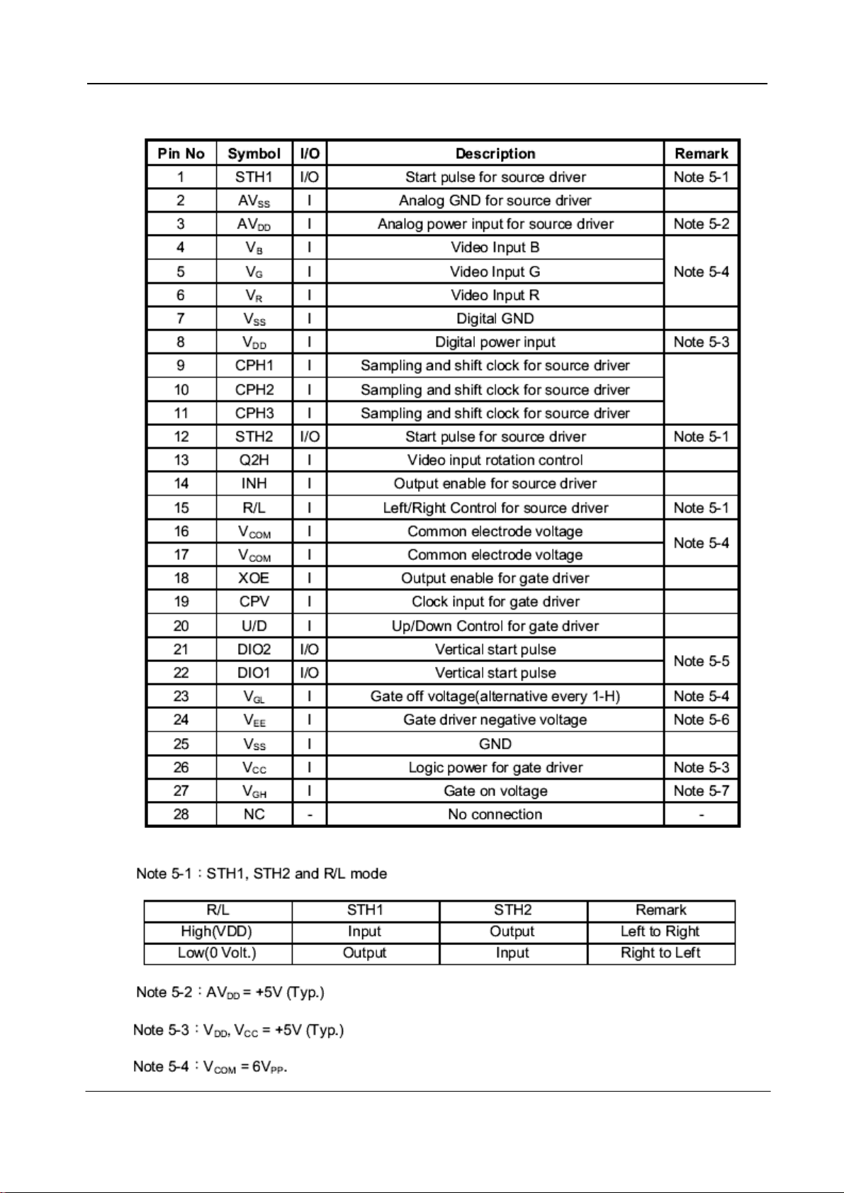
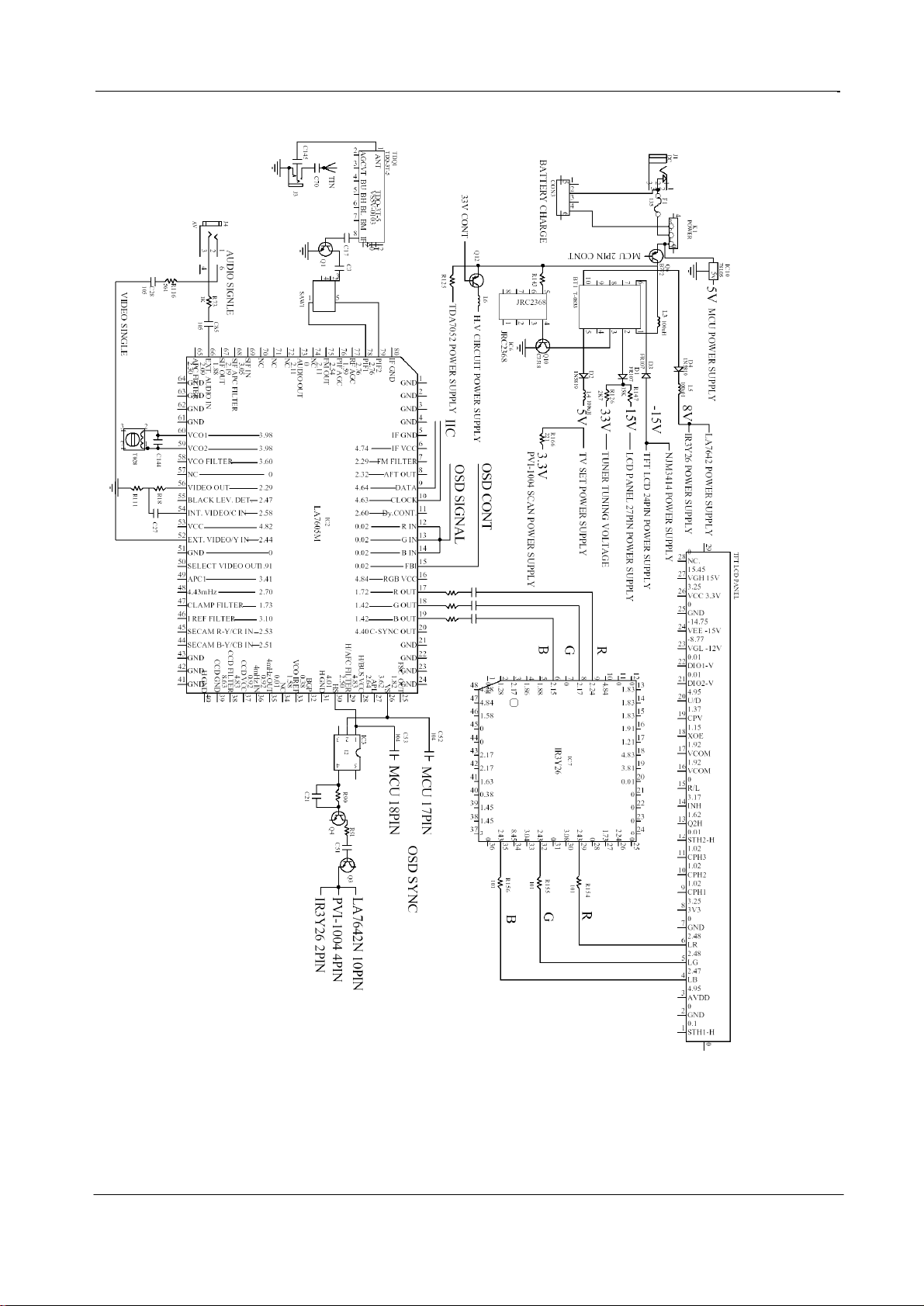
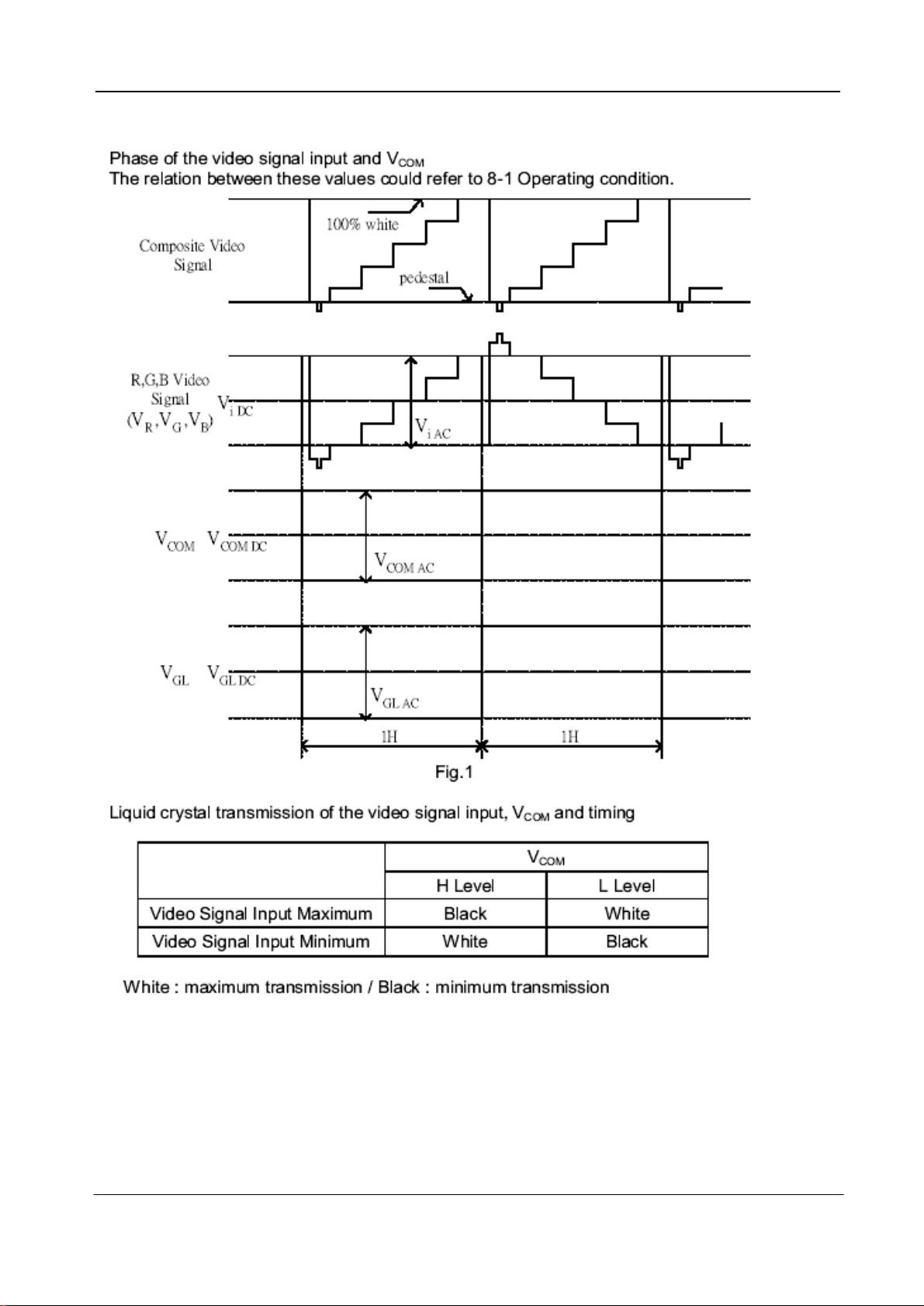
LCD PANEL INPUT/OUTPUT TERMINALS
- 5 -
Page 6
- 6 -
Page 7
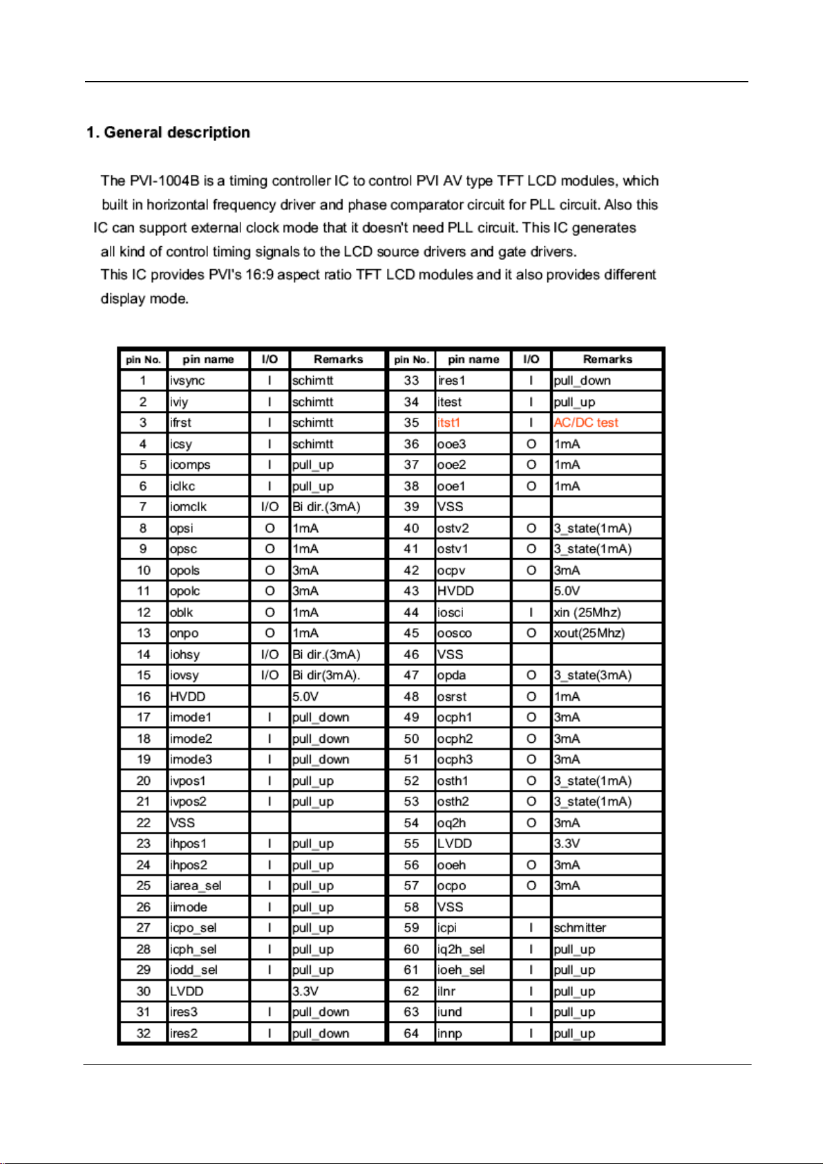
PVI-1004B FRAME DIAGRAM AND PIN FUNCTION
2.PIN ASSIGNMENT
- 7 -
Page 8

3.PIN DESCRIPTION
- 8 -
Page 9

- 9 -
Page 10

- 10 -
Page 11

LA7642N FRAME DIAGRAM AND PIN FUNCTION
- 11 -
Page 12

TDA7052 FRAME DIAGRAM AND PIN FUNCTION
A. THE FRAME DIAGRAM
B. THE PIN FUNCTION
- 12 -
Page 13

NJM2377 FRAME DIAGRAM AND PIN FUNCTION
- 13 -
Page 14

24C08 FRAME DIAGRAM AND PIN FUNCTION
- 14 -
Page 15

NJM3414 FRAME DIAGRAM AND PIN FUNCTION
- 15 -
Page 16

IR3Y26 FRAME DIAGRAM AND PIN FUNCTION
- 16 -
Page 17

- 17 -
Page 18

IR3Y26 FRAME DIAGRAM AND PIN FUNCTION
R
POWER
NC
PIN CONFIGURATION:
1
2
VOL
VT
VSS
XT1
XT2
VDD
NC
KEY
AFT
CHROMA
LNA
UHF
BAND2
BAND1
REM
SD
BACKWARD
ENABLE
SCL1
SDA1
SCL0
SDA0
B
VS
RES
FILT
NC
CVIN
HS
G
I
BL
NC
- 18 -
Page 19

THE PROGRAM DIAGRAM REPAIRING BLACK AND WHITE TV
TO START
YES YES YES YES YES
RASTER?
YES/NO
NORMAL
RESTER?
TES/NO
PICTURE?
YES/NO
NORMAL
PICTYRE?
YES/NO
NORMAL
SOUND?
YES/NO
NO NO NO NO NO
PART 1
PART 2
PART 3
PART 4
PART 5
REPAIR REPAIR REPAIR REPAIR REPAIR
YES
End
NORMAL
color
YES/NO?
NO
REPAIR
PART 6
- 19 -
Page 20

PART 1 RASTER YES/NO?
TROUBLE PHENOMENON SOLVING ACTION
1 NO RASTER AND NO SOUND SIGNAL
2 NO RASTER AND HAVE SOUND
PART 2 NORMAL RASTER YES/NO?
TROUBLE PHENMENON SOLVING ACTION
1 RASTER TOO CLUTTER
2 RASTER TOO DARK
PART 3 PICTURE YES/NO?
TROUBLE PHENMENON SOLVING ACTION
1 NO PICTURE
2 NOISE AND WAVE (VIDEO)
3 NO NOISE AND WAVE (VIDEO)
4 SCANNING RETRACE LINE
·CHECK AC ADAPTOR CONNECTION
·REPLACE FRESH BATTERIES
·H.V CIRCUIT OR LCD PANEL.
·LCD PANEL IS BAD
·CHECK PVI-1004B (LCD DRIVER)CIRCUIT
·LCD PANE IS BAD
·H.VOLT CIRCUIT IS BAD
·MAKE SURE THE ANTENNA IS NOT BROKEN
·ADJUST THE BRIGHTNESS AND CONTRAST
CONTROLS
·ANTENNA OR HIGH FREQUENCY AMPLIFIER OR
TUNER
·TUNER OR IF AMPLIFIER OR AGC
·VIDEO FREQUENCY AMPLIFIER CIRCUIT
PART 4 NORMAL RASTER YES/NO?
TROUBLE PHENMENON SOLVING ACTION
THE VERTICAL AND HORIZONTAL
1
FREQUENCY ARE NOT SYNCHRONIZE.
THE VERTICAL FREQUENCY IS NOT
2
SYNCHRONIZE
3 INTERFERED
4 SOFT PICTURE OR NO CLEAR
PART 5 NORMAL SOUND SIGNAL YES/NO?
TROUBLE PHENMENON SOLVING ACTION
NO SOUND SIGNAL OR LIGHT SOUND
1
VOICE OR SOUND SIGNAL DISTORTION
PART 6 NORMAL COLOR YES/NO?
TROUBLE PHENMENON SOLVING ACTION
1 NO COLOR
·PUBLIC CHANNEL OR AGC OR SYNCHRONIZING
SEPARATION CIRCUIT
·VERTICAL OSCILLATOR OR INTEGRATED CIRCUIT
·AFC CIRCUIT OR HORIZONTAL
OSCILLATOR OR POWER SUPPLY ORINTERFERED
BY POWER SUPPLY AND OUTSIDE OR HORIZONTAL
OUTPUT OR SOUND SIGNAL ABSORBING ETC
·TUNER OR PICTURE CHANNEL OR AGC OR VIDEO
FREQUENCY AMPLIFIER
·SOUND SIGNNAL CHANNEL
·CHECK COLOR DECODE CIRCUIT(IR3Y31)
- 20 -
Page 21

654321
12
11
10
9
R68
151
RF
SD
9V
8V
-15V
15V
R93
10K
33V
5V
CON1
28PT
STH1-H1GND2AVDD 3LB4LG5LR6GND73V38CPH19CPH210CPH311STH2-H12Q2H13INH14R/L15VCOM16VCOM17XOE
0.1
0
4.95
2.47
2.48
2.48
0
3.25
1.02
1.02
1.02
0.01
1.62
3.17
0
1.92
1.92
18
U/D20DIO2-V21DIO1-V22VGL -12V23VEE -15V24GND25VCC 3.3V26VGH 15V27NC.
CPV
1.15
1.37
4.95
0.01
0.01
-8.77
-14.75
19
0
3.25
IF
C13
103
R118
22K
R117
22K
C41
220P
C14
R157
101
J4
AV
1
2
34
R88
10K
0.16134.08148.45150.20
LA7642N
103
CON2
SPACK
R116
561
C28
105
IC11
C49
104 C50
C112
105
3V3
J2
EAR
R24
151
C82
100P
L7
22uH
11012
STH1
9V
33V
AGC
5V
R66
101
8V
C4
104
IF
C17
103
5V
AFT
SDA
SCL
R65
101
C2
103
RI
GI
BI
BLACK
5V
RO
GO
BO
SD
VS
HS
R64
101
Q12
2SA8550
R101
100K
R14
1K
R6
100K
R5
100K
R31
5K6
220uF/16V
C99
330P
C8
103
R112
R1133K9
R114
R13
1K
5V
R28
1K
221
Q1
2SA9018
C22
3K9
3K9
Q9
2SC1815
R30
R29
10
C25
105
C98
330P
C87
10uF/10V
R19
1K
C26
105
VB
R1
27K
R36
33K
VG
L6
470uH
C126
220uF/16V
R110
8K2
SAW1
38.9
C3
103
1
2
3
4
5
C1
6
103
7
8
9
10
11
12
13
14
15
16
17
18
19
20
21
22
23
24
R86
10K
VR
GND
GND
R38
33K
R34
4K7
Q15
D1863
R35
4K7
Q14
D1863
C44
10uF/50V
345
2
80
3V3
CPH1
CP H2
CP H3
STH2
Q2H
INH
C115
223
RF AGC
BT4
76
1.59
PIF AGC
T-0835
1
12
2
13
3
14
4
16
5 6
11
C116
223
C19
103
75
2.11
2.54
FM OUT
C147
39P/3KV
9
8
17
7
15
R85
10K
73NC74
C90
472
R84
10K
R16
1K
69NC70NC71NC72
1
2
C79
10P
0
2.11
SIF IN
C148
104/100V
C18
103
R22
1K
1
77
79
PIF178PIF2
2.76
2.76
IF GND
AUDIO OUT
GND
GND
IF GND
IF VCC
FM FILTER
AFT OUT
DATA
CLOCK
Dy.CONT.
R IN
G IN
B IN
FBI
RGB VCC
R OUT
G OUT
B OUT
C-SYNC OUT
GND
4.74
2.29
2.32
4.64
4.63
2.60
0.02
0.02
0.02
0.02
4.84
1.72
1.42
1.42
4.40
IC2
LA7605M
3.98
3.98
3.60
0
2.29
BLACK LEV. DET.
2.47
2.58
4.82
EXT. VIDEO/Y IN
2.44
0
SELECT VIDEO OUT
1.91
3.41
2.70
1.73
3.10
SECAM R-Y/CR IN
2.53
SECAM B-Y/CB IN
2.51
GND
GND
GND
1.82
3.62
2.64
4.83
2.50
4.01
0.38
1.58
0.01
0.92
R39
33KR40
R8
47K
R173
0
Q3
2SC1815
R21
1K
0.92
FSC OUT25VS26APL27H/BUS VCC28H/AFC FILTER29HS30H GND31BGP32VCO IREF33NC344mHz OUT354mHz IN36CCD VCC37CCD FILTER38CCD GND39H GND
R32
R89
10K
33K
R42
33K
R91
10K
Q4
2SC1815
4K7
R122
150K
C51
104
C38
R45
333
3K3
C34
105
C88
R41
33K
1 2 3
IC3
I2
10uF/10V
C11
103
45
R90
47K
C21
102
5V
VCOM
XOE
R96
CON6
10K
2P/3.5
C141
2.2uF/10V
C84
R125
105
47
C146
103
C7
105
68
3.05
C93
474
C81
102
R105
331
66
67
2.09
1.88
2.19
GND
SIF OUT
GND
GND
EXT. AUDIO IN
SIF APC FILTER
GND
VCO1
VCO2
VCO FILTER
VIDEO OUT
INT. VIDEO/C IN
VCC
GND
APC1
4.43mHz
CLAMP FILTER
I REF FILTER
GND
GND
GND
4.83
8.63
40
C86
10uF/10V
C89
C12
10uF/10V
103
65
NC
VGL
out-
n.c.
gnd
out+
7
C43
2.2uF/10V
-15V
8
7
6
5
6
R115
75
C24
10uF/10V
DIO1
DIO2
5V
CPV
R59
22K
C149
104
2.30
64
63
APC FILTER
62
61
60
59
58
57
R18
56
1K
55
54
53
C27
105
4
3
2
1
C140
470uF/16V
C85
105
P-56P
N-33P
C144
56P
C91
102
R120
680K
IC5
TDA7052
cont
gnd
in+
vcc
R73
1K
R7
47K
BT3-T028
T028
2 3
1
R111
1K5
52
51
50
49
18P
C48
C36
105
R17
1K
C80 102
X2-4.43
4.433619
48
47
46
45
44
43
42
R74
41
4K7
C92
474
16
C33
473
R124
2M
C94
474
C16
103
3.9314.1326.3636.9445.3754.4864.4470
C113
105
C114
105
C109
105
C110
C111
105
105
8V
15V
SECAM
C15
103
8
104
290
R150
12K
15.45
0
104
104
104
104
C59
C60
C61
C62
28
NC
1.83
1.83
NC
R1
G1
地
B1
同步输出
组合放大
同步分离
NC
4.84
1.58
48
33K
DIO1
DIO2
XOE
R136
3K9
VSS39ooe138ooe237ooe3
C133
10uF/10V
C78
104
0
12
C135
0
B213G214R2
10uF/10V
11
4.84
10
C71
1电源
2.24
104
R131
R130 1K5
R129 1K5
R16030K
C72
104
R152
51K
1K5
RO
GO
BO
C30
9
2.17
104
8
C29
0
104
7
2.15
6
C31
1.88
104
5
1.86
4
2.17
3
1.28
2
1
4.28
D
C
SYNC
36
34
33
LVDD
iodd-sel
icph-sel
icpo-sel
iimode
iarea-sel
ihpos2
ihpos1
imodel3
imodel2
imodel1
R98
10K
2
7
ires2
ires3
VSS
ivpos2
ivpos1
16
1
8
ires1
R149
15K
32
31
30
29
28
27
26
25
24
23
22
21
20
19
18
17
VGL
4.7uF/25V
R168
20K
R95
10K
3V3
3V3
C142
5V
R44
33K
R60
22K
B
VCOM
A
45
R99
10K
NJM3414
3
6
itst135itest
R97
10K
IC8
9V
VR
5V
VG
8V
VB
R151
51K
R153
62K
R154
R155
101
R156
101
C134
220uF/16V
C65
104
R9
47K
R4333K
101
C63
104
C64
104
25
NC
0
0
0
0
26
Y0校正
2.24
27
Y0校正
1.73
28
GND
0
29
RO
2.43
30
R直流检测
3.08
31
GND
0
32
GO
2.43
33
G直流检测
3.04
34
2电源
8.45
35
BO
2.43
36
NC
0
B直流检测37B通道副亮度调节38R通道副亮度调节39RGB放大调节40亮度调节41B通道副对比度调节42R通道副对比度调节43NC44组合翻转信号输入45翻转信号输入46同步输入47同步输出
3
1.45
C66
104
C67
104
68K
0
1.45
R158
R58
22K
C68
104
0
0.38
R10
47K
19NC20NC21NC22NC23NC24
3.81
行滤波器输出
IC7
IR3Y26
1.67
C73
104
R159
22K
4.83
2.17
17开关18
1.21
2.17
R12
47K
R119
22K
调整输出
C69
104
1.91
0
16
行滤波器输入端
15
1.83
对比度调节
0
R11
36K
R146
H/2
CPV
BT2-T029
C137
T029
D5
82P
T1
R142
100K
7
C100
56P
1
2 3
R25
1K
R137
3K9
R163
561
C138
682
R148
15K
R167
C32
105
20K
C46
18P
3V3
46
45
44
43
42
151
R169
CPH1
5V
CPH2
CPH3
C101
C102
100P
100P
STH1
STH2
Q2H
3V3
INH
VR2
C139
220P
R135
50K
2.4991.28104.28
VS
SYNC
R164
H/2
561
5V
SYNC
R170
C103
100P
R1343K9
C76
104
R161
2K2
R166
221
C125
10uF/10V
3K9
151
R171
49
ocph1
osrst48opda47VSS
50
ocph2
51
ocph3
151
52
osth1
53
osth2
54
oq2h
55
LVDD
56
ooeh
57
ocpo
58
VSS
59
icpi
60
iq2h-sel
61
ioeh-sel
62
ilnr
63
iund
64
innp
ivsync1iviy2ifrst3icsy4icomps5iclkc6iomclk7opsi8opsc9opols10opolc11oblk12onpo13iohsy14iovsy15hvdd
R165
561
R26
1K
R94
10K
C75
104
C136
105
iosci
oosco
HVDD
40
ocpv
ostv141ostv2
IC4
PVI1004C
R162
561
-15V
33V
7
C23
10uF/10V
C105
4.7uF/25V
R49 22K
R52 22K
R48 22K
R50
22K
R51
22K
R82
10K
R83
10K
R63
101
8
SCL
VCC
A01A12A23A3
C123
220uF/16V
C54
104
C20
103
AGC
5V
SCL
SDA
IC9
24C08
C57
104
UPC574
ZD3
C124
220uF/16V
R4
27K
VR1
1K
R139
2K2
TDQ1
TDQ-3T-5
TIN
J3
R79
22K
R37
33K
D
C
IC10
78L05
C47
18P
C45
15P
L2
22uH
R108
681
R107
1K5
C108
C10
220uF/16V
5v
R55
22K
R87 10K
X1-32K
32K
R106 390K
C107
10uF/10V
C6
103
R92
10K
R56
22K
Q5
R109
8K2
ZD1
3V9
R70
4K7
103
1
PWM
5.00
2
POWER
4.83
3
VT
3
4
VSS
0
5
XT1
1.96
6
XT2
2.36
7
C9
VDD
103
4.94
8
NC
0
9
R80
KEY
10K
0
10
AFT
2.32
11
CHROMA
2.58
12
PWM
5.00
2SA1015
C5
103
C39
C40
220P
R54
22K
0
-RES13FILT14CVIN15NC16-VS17-HS18R19G20B21BL22I23NC
C35
R2
27K
180P
R53
22K
45
47NC48
0
5.00
5.00
105
SCK0
PWM146PWM2
4.98
3.61
4.92
C52
331
R104
104
R103
C42
270K
2.2uF/10V
AFT
SECAM
LL-MB38
104
2
1
2
3
4
5
67
220uF/16V
F1
135
123
5 6
CON3
BT
RF1
3
1
R57
22K
D6
LED
C117
2SA8550
4
2SC1815
R172
1R0
Q11
AV/TV
MENU
C58
104
SW1
AUTO
SW2
SW3
SW4
VOL-
SW5
VOL+
SW6
CH-
SW7
CH+
Q7
R23
1K
R128
1K5
R127
2K7
R133
3K9
R33
4K7
R132
8K2
R3
27K
R123
150K
Q6
B772
Q8
2SC1815
R81
10K
R100
10K
R144
180K
C143
CON4
6P
0
B
K1
POWER
1
0
2
3
4
J1
A
1
DC
1
2
2
3
3
TIN
R78
22K
C97
104
Q2
2SC1815
43
44
0.
0.
0.
SI0
SO0
IC1
LC86F3264A
0
3.26
3.83
C53
104
RIGIBI
HSVS
0
CON5
6P
L3 100uH
C119
220uF/16V
6
7
8
9
10
BT1
T-0833
R143
C131
47R
10uF/10V
C83
102
R121
680K
C130
10uF/10V
R77
22K
4.92
0.01
R69
4K7
1
2
3
4
5
67
JRC2377
41NC42
C96
104
RF
R72
4K7
IC6
1
ANT
C145
102
AGCVTBUBHBLBM8IF
2
C95
104
4.92
0.01
R15
22K
0
0.02
3
C37
104
4.68
4.92
0.01
0.01
5.00
REM
4.44
INT2
5.00
INT1
5.00
INT0
0.02
SCL1
0.02
SDA1
4.62
SCL0
4.68
SDA0
0.02
C106
4.7uF/25V
P0337P0438P0539P0640P07
P02
P01
P00
NC
R76
22K
4.92
0.01
24
R46
R71
R75
3K3
4K7
4K7
R47
3K3
BLACK
Q13
R102
2SA1015
10K
D4
1N5819
C122
220uF/16V
FR107
1
2
3
4
5
D3
C118
220uF/16V
D1
FR107
C128
10uF/50V
1N5819
D2
C120
220uF/16V
L5
100uH
C121
220uF/16V
220uF/16V
C132
45
3
6
7
8
R145
36K
C56104
2
JRC2368
1
R141
100K
456
C104
4.7uF/25V
36
35
34
0
33
32
31
30
29
28
27
26
25
0
R62
101
5
4
C77
104
R147
15K
R126
2K7
C55
104
L4
C74
R138
2K2
R140
6K8
TDQ-3T-5
VS5V-0103
R61
101
6NC7
SDA
C129
10uF/50V
C127
10uF/50V
100uH
220uF/16V
Q10
C3518
1 2 3 4 5 6
Page 22

1
2
4
17
19
3
11
10
6
16
21
20
18
22
23
7
8
15
9
14
13
12
APPROVE:
COLLATE:
scale:
fit
unit:
mm
DESIGN:
FILE S/N:
FILE NAME
232221
BATTERY BOX(BACK)
SCREW
20
BATTERY FIX SWITCH
BATTERY PLUG 1
1918171615
SPRING
BATTERY BOX(FRONT)
BATTERY FIX UNIT
LI-ION BATTERY 1
5
14
SCREW
SCREW
MAIN CASE(BACK)
ROD ANTENNA 1
9
MAIN PCB
KEY PCB
SCREW
6
7
8
TFT LCD MODULE 1
SCREW
FIX FLAKE
3
5
4
KEY
SPEAKER
SCREW
10
11
12
13
S/N
1
2
KEY UNIT
MAIN CASE(FRONT)
PART NAME Q.T.Y
page:
1
1.0
ver:
1
1
2
PA2.0x6mm
ABS
ABS
1
1
1
ABS
ABS
1
3
PA2.0x6mm
FM2.0x8mm
ABS1
1
1
4
PA1.7x6mm
4
PA2.0x6mm
1
4
PA2.6x8mm
1
1
1 ABS
4
ABS
ABS
REMARK
 Loading...