

Roadstar DVD-5105 Service Manual

Service Manual
- DVD-5105
R
DVD-5105
Service Manual
- DVD-5105
5
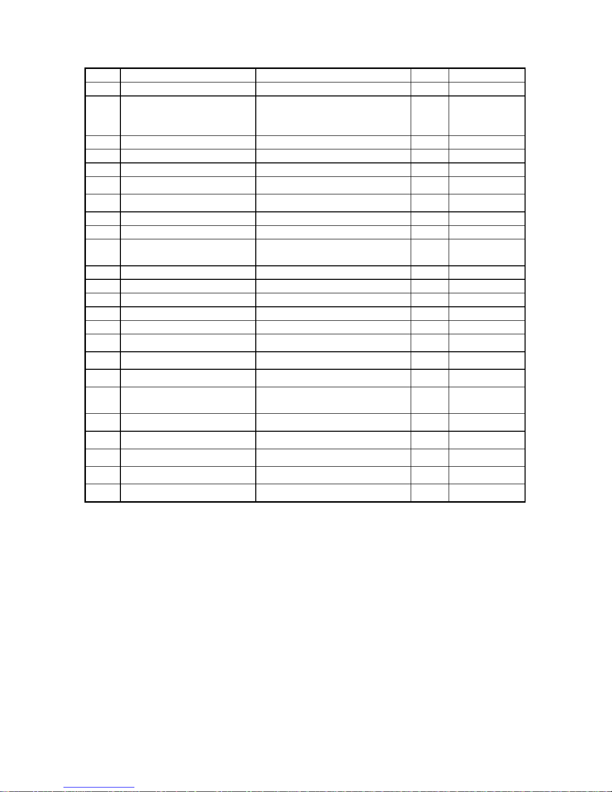
No. Name Specification Q’ty /Note
1 NTSC/PAL PVM-14N6E 1
2 EC TV (14”) Schneider STV 365 1 AC
230V~50Hz
50Watt
3 Transformer 220V 1
4 Oscillator OS-9100D 100MHZ 3
5 Video/Audio Cable Lotus terminal 3
6 Video Cable Lotus terminal 1
7 S-video Cable 1
8 DVD Power Cable 1
9 CBS test disc 1
10 NF-200 test disc PAL Navigation Files Test Disc
V1.1
1
11 TCD-731RA test disc Vertical Deviation 0.54~1.0mm 1
12 SBC444A test disc Phillips Test Disc 1
13 DVD-Karaoke test disc Single side double layer 1
14 MP3 test disc CD 1
15 Remote Controller RMC-300 for DVD-V300 1
16 Earphone
6.3φload 32 ohm
1
17 AV Selector 1
18 Earphone jack (adapter) 1
19 BNC male to RCA female
adapter
12
20 BNC Three Female 2
21 Plastic Bowl 6 For test discs
22 Earphone tool 1
23 SCART Cable 2
24 SCART testers 1
II DVD Player Error Code
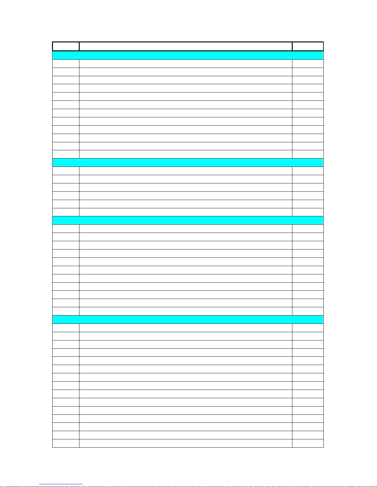
6
CODE Description of Trouble Note
Power Test
T01 No Power
T02 Power LED off or in poor brightness
T03 Abnormal LED display or no display at all.
T04 Time-consuming loading
T05 Remote controller in poor contact or not working.
T06 Run In after turning unit on, no test available.
T07 System breakdown after turning unit on.
T08 System breakdown during play.
T09 Wrong F/W version or version can not be changed.
T0A Unit burnt out.
T0B Unsteady turn on.
T0C Noise in unit.
Disc Drive Test
T10 Noise in disc drive
T11 No Disc
T12 Disc drive does not work or gets stuck
T13 Disc tray does not reset
T14 Disc drive scratches discs
T15 Disc skip (does not play CD, VCD or DVD)
Video Test
T20 No image/abnormal (please mark abnormality)
T21 Video 1 No image/abnormal (please mark abnormality)
T22 Video 2 No image/abnormal (please mark abnormality)
T23 S-Video No image/abnormal or B/W (please mark abnormality)
T24 Abnormal VCD image (please mark abnormality)
T25 Abnormal DVD image (please mark abnormality)
T26 Abnormal NF-200 image (please mark abnormality)
T27 SCART Video No image/abnormal (please mark abnormality)
T28 SCART S-Video No image/abnormal (please mark abnormality)
T29 Abnormal on-screen subtitle or no displays at all
TA0 Abnormal menu setting (please mark abnormality)
Audio Test
T30 Audio 1/left channel no waveform (audio) or abnormal waveform (audio)
T31 Audio 1/right channel no waveform (audio) or abnormal waveform (audio)
T32 Audio 2/left channel no waveform (audio) or abnormal waveform (audio)
T33 Audio 2/right channel no waveform (audio) or abnormal waveform (audio)
T34 AC3 no waveform (audio) or abnormal waveform (audio)
T35 TCD-731RA noise
T36 TCD-712 noise
T37 SBC444A noise
T38 Karaoke VCD noise
T39 Karaoke DVD noise
TB0 CBS no waveform (audio) or abnormal waveform (audio)
TB1 MP3 noise
TB2 Audio no waveform (audio) or abnormal waveform (audio)
TB3 SCART Audio no waveform (audio) or abnormal waveform (audio)
TB4 SCART Audio left no waveform (audio) or abnormal waveform (audio)
7
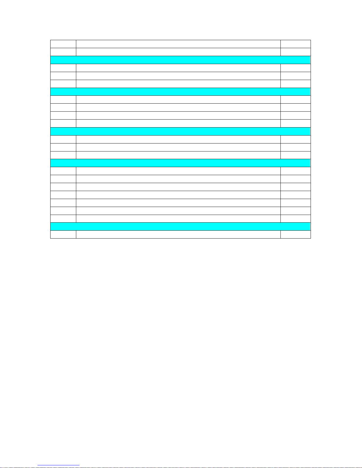
TB5 SCART Audio right no waveform (audio) or abnormal waveform (audio)
TB6 OPTICAL no waveform (audio) or abnormal waveform (audio)
Earphone Test
T40 Earphone no sound or sound with pause, noises, interference or echo.
T41 Earphone (right) no sound or sound with pause, noise or interference.
T42 Earphone (left) no sound or sound with pause, noise or interference.
Function Key Test
T61 Image does not pause or stop
T62 No fast-forward or rewind
T63 Panel buttons does not work
T64 Shuttle multiplication in abnormal display or off
System Setting Test
T71 Unsuccessful entry to system setting.
T72 No play or system breakdown after system setting.
T73 Region code can not be set or unable to enter
Appearance Test
T81 Scratches, large gaps, illegible or wrong characters.
T82 Slipping screws
T83 Missing parts
T84 Poor assembly
T85 Poor raw material
T86 Wrong parts
T87 Foreign materials inside
Other Tests
T99 Others

8
IIIMechanical Appearance Diagram
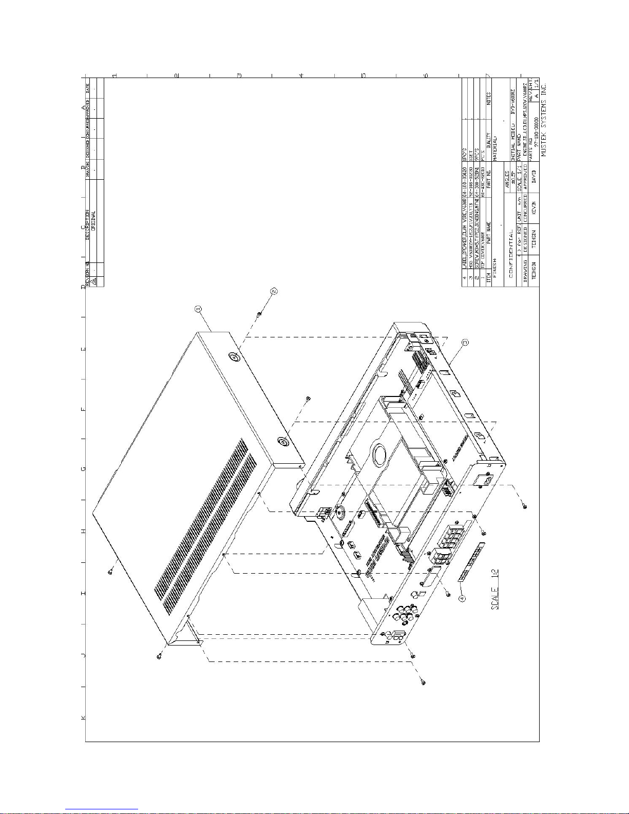
9
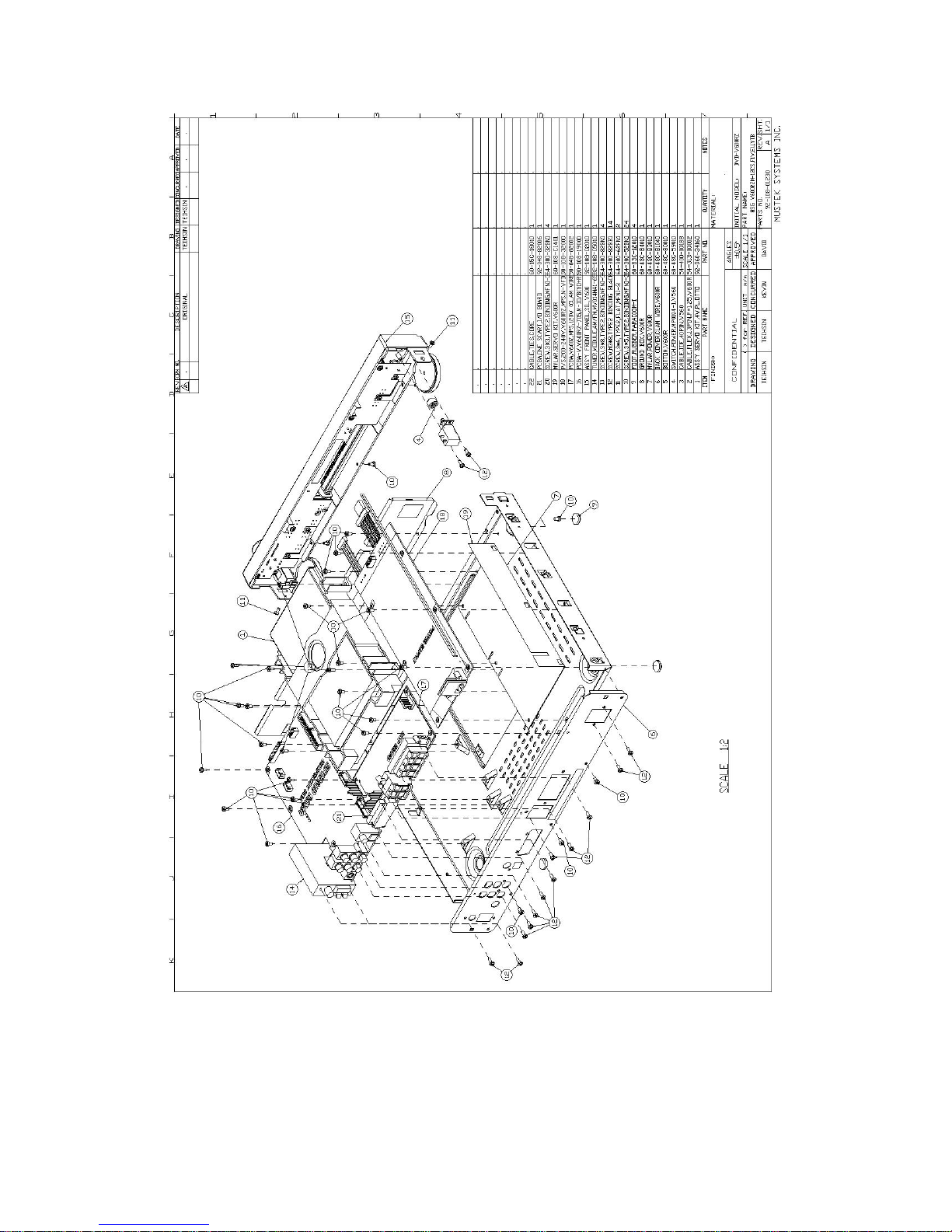
10
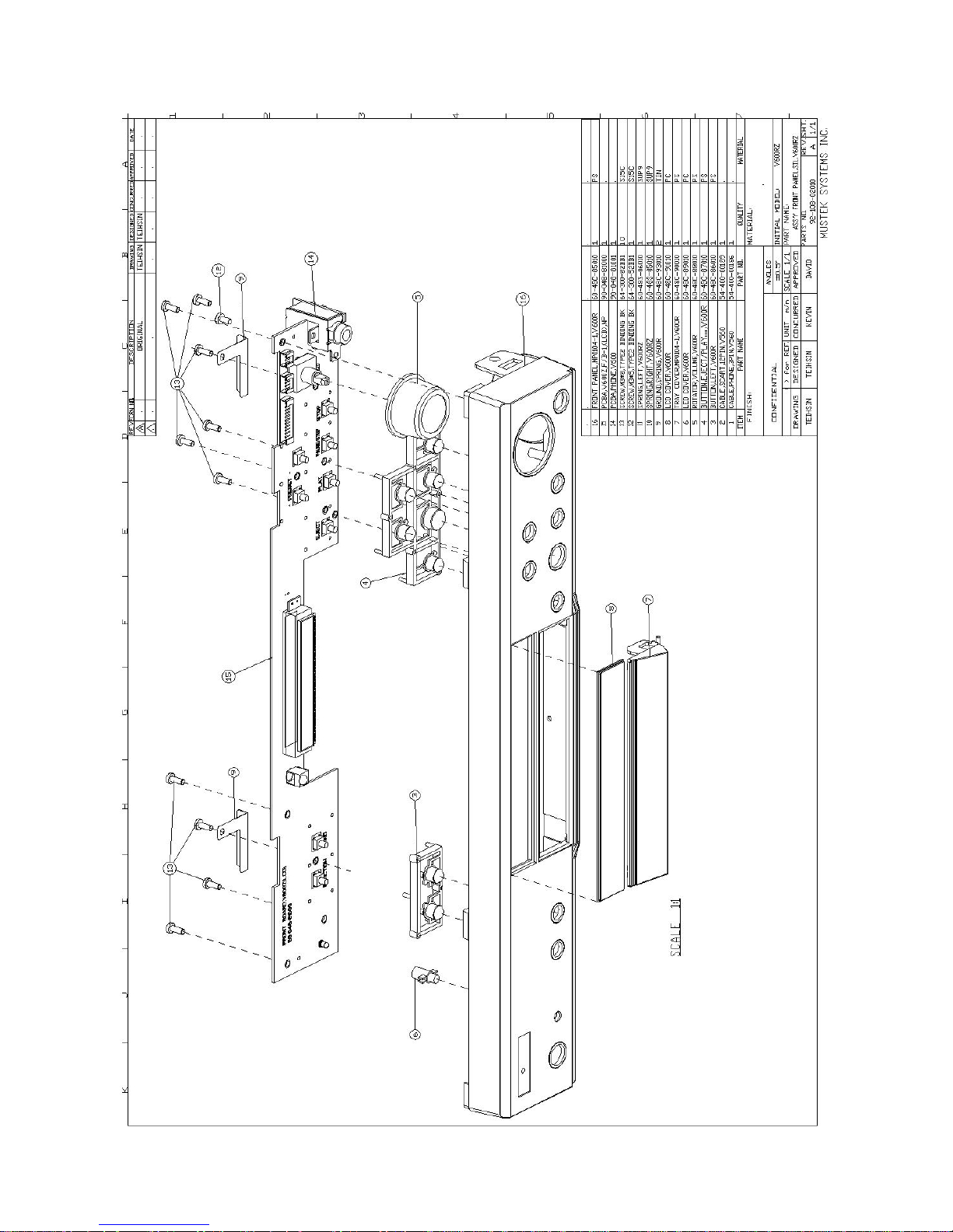
11

12
IVMaintenance
T01No Power
1. Power Board
- Remove the top cover and check if the 12pin Cable connected to the Power Board is
correctly plugged on the right position, or you may have to plug it again for a test.
- If the above step does not work, remove the fixation screw from the Power Board and
replace the Power Board.
2. MAIN BOARD
- Remove the top cover by removing the F/W first and replace a new F/W or plug the
F/W correctly before checking for normal function.
- Check if the 12pin Cable connected to the MAIN BOARD is correctly plugged on the
right position, or you may have to plug it again.
- If the above step does not work, the MAIN BOARD can be NG and replace the MAIN
BOARD.
T02Power LED off or in poor brightness
1. Front Board
- Remove the top cover and the front panel and check if the Front Board LED is
damaged or reversed polarity.
- Check if the 4 pin Cable connecting Front Board and Front Board is correctly plugged
on the right position, or you may have to plug it again.
- Test U1 Pin 42 to see if the voltage is low when Power goes ON. Be sure that U1 Pin
41 is Hi. Otherwise, it would suggest that U1 is NG.
- If the above step does not work, it would suggest that Front Board is NG, change the
Front Board.
T03Abnormal front panel LCD display or no display
1. Front Board
- Remove the top cover by removing the front panel first and check if the PIN of the
LCD MODULE experiences short circuit or breakage.
- Check if U3 Pin4~42 on the Front Board has signal output (Check for cold welding,
missing welding and polarities of the parts).
- Check if the 12pin Cable linking the Main Board and the Front Board is correctly
plugged on the right position, or you may have to plug it again.
- If none of the above steps works, replace the Front Board.
2. Main Board
- Remove the top cover and check if the 40 pin Cable connecting DVD-ROM and Main
Board is correctly plugged on the right position, or you may have to plug it again.
- Check J22 and J23 connector pin for missing welding, cold welding, wrong parts or
reverse welding.
- Remove F/W and replace a new F/W or plug F/W again. Check if it works correctly.
- If none of the above steps works, it would suggest MAIN BOARD or DVD-ROM is
NG, replace it.
3. Power Board

13
- Remove the top cover and check if the 12 pin Cable connected to the Power Board is
correctly plugged on the right position, or you may have to plug it again for a test.
- Use a universal wattmeter or an oscillator to test for 5V between Main Board J13 Pin 3
and GND, if not, it would suggest poor Power Board.
- If the above steps do not work, remove the fixation screw from the Power Board and
replace Power Board.
T04Time-consuming loading
1. Main Board
- Remove the top cover and check if the 40 pin Cable connecting DVD-ROM and Main
Board is correctly plugged on the right position, or you may have to plug it again.
- If none of the above steps works, it would suggest MAIN BOARD or DVD-ROM is
NG, replace it.
T05Remote Controller in poor contact or does not work
1. Remote Controller
- If this device does not work correctly, first check if the power supply is all right, if not,
replace the battery.
2. Front Board
- Remove the top cover by removing the front panel and check for short circuit,
breakage, missing welding on U1 and check for 5V output on U1 pin 56.
- Use a universal wattmeter or an oscillator to test FRONT BOARD U4 PIN 1 and press
on the remote controller to test for any signal out put, if no out put, replace U4.
- Check if 12pin Cable connecting Main Board to Front Board is plugged correctly on
the right position or you may have to plug it again.
- If none of the above steps works, replace Front Board or Main Board.
T06Run In after turning on, no test available
1. Main Board
- Remove the top cover and replace with new F/W.
- If none of the above steps works, replace Main Board.
T07System breakdown after turn on
1. Main Board
- Remove the top cover and check if all Flat Cables connected to the inside of the device
is plugged correctly on the right position, or you may have to plug it again.
- Remove F/W and replace it with a new F/W or plug F/W correctly before checking if it
works correctly.
- If none of the above steps works, replace MAIN BOARD.

14
T08System breakdown during play
1. Main Board
- Remove the top cover and check if all Flat Cables connected to the inside of the device
is plugged correctly on the right position, or you may have to plug it again.
- Remove F/W and replace it with a new F/W or plug F/W correctly before checking if it
works correctly.
- If none of the above steps works, replace MAIN BOARD.
2. DVD ROM
- Check DVD Loader for unsteadiness (skip discs), if yes, replace it.
3. DVD DISC
- Check the test disc for severe scratches or circular, curved scratches, if yes, replace the
test piece before testing again.
T09F/W in wrong version or version can not be changed
- Remove the top cover and update the MAIN BOARD F/W before proceeding with the
test.
T0ADevice burnt out
1. F/W
- Check MAIN BOARD F/W for reverse polarities, if yes, replace it or install it
correctly.
2. PCBA
- Check and verify PCBA of burnt unit and replace it.
T0BUnsteady turn on
1.Main Board
- Remove the top cover and check if all Flat Cables on the inside are plugged on the
right position, or you may have to plug them again.
- Remove F/W and replace it with a new one or plug F/W again before checking if it
works well.
- If none of the above steps works, replace MAIN BOARD.
T0CNoise in unit (noise when turning on unit)
1. DVD ROM
- Check for source of noise in DVD-ROM. If yes, replace it.
T10Noise in disc drive
1. DVD ROM
- Check for source of noise in DVD-ROM. If yes, replace it.

15
T11NO DISC
1. Main Board
- Remove the top cover and check if the 40 pin Cable connecting DVD-ROM and Main
Board is correctly plugged on the right position, or you may have to plug it again.
- Check the resistors or bus resistors on Main Board J12 for missing welding, cold
welding, wrong parts or reverse welding.
- If none of the above steps works, replace Main Board.
2. DVD ROM
- Check if DVD-ROM does not read, if not, replace it.
T12Disc drive does not work or gets stuck
1. Main Board
- Remove the top cover and check if the 40 pin Cable connecting DVD-ROM and Main
Board is correctly plugged on the right position, or you may have to plug it again.
- Check if caused by poor assembly.
- If none of the above steps works, replace it.
T13Disc drive does not reset
1. DVD ROM
- Replace disc drive.
- Check if caused by poor assembly or parts.
T14Disc drive scratching discs
1. Main Board
- Replace disc drive.
T15Disc skip
1. DVD ROM
- Replace disc drive.
T20No Image/ Abnormal
1. Main Board
- Remove the top cover and check if the 40 pin Cable connecting DVD-ROM and Main
Board is correctly plugged on the right position, or you may have to plug it again.

16
- Use a universal wattmeter or an oscillator to test for 5V between Main Board J13 Pin 2,
3 and GND, if not, test if RX7 produces 5V, if so, go to the next step.
- Use an oscillator to test if Y2 creates 27MHz, if not, check C58 and C59 to see if its to
be 22P. Eliminate missing and cold welding. If X301 is NG, replace it.
- Check if U10 is in poor contact or F/W IC with problem.
- If none of the above steps works, replace MAIN BOARD.
2. DVD ROM (rare)
- If it does not work by replacing Main Board, replace DVD ROM.
T21Video 1 No image/abnormal
1. Main Board
- Remove the top cover and check if the Flat Cables connected to the inside of the
device are properly plugged in the right position, or plug them correctly.
- Check J13 of Pin 2 for missing and cold welding, if yes, remove them.
- Check post CVBS RLC for missing welding or cold welding, wrong parts, short circuit
or interruption, if any, eliminate it.
- If none of the above steps works, check U15 for missing and cold welding, if any,
eliminate it.
- If none of the above steps works, replace MAIN BOARD.
T22Video 2 No image/abnormal
2. Main Board
- Remove the top cover and check if the Flat Cables connected to the inside of the
device are properly plugged in the right position, or plug them correctly.
- Check J13 of Pin 2 for missing and cold welding, if yes, remove them.
- Check post CVBS 1 RLC for missing welding or cold welding, wrong parts, short
circuit or interruption, if any, eliminate it.
- If none of the above steps works, check U15 for missing and cold welding, if any,
eliminate it.
- If none of the above steps works, replace MAIN BOARD.
T23S-Video No image/abnormal or B/W
1. Main Board
- Check post Y_OUT and C_OUT RLC for missing welding or cold welding, wrong
parts, short circuit or interruption, if any, remove it.
- If none of the above steps works, check U15 for missing and cold welding, if any,
eliminate it.
- If none of the above steps works, replace MAIN BOARD.
T24VCD display abnormal

17
1. Main Board
- Check U15 for missing, cold-welding or short-circuit and eliminate if any.
- Check U6, X2, U14 and U15 for missing welding or cold welding and eliminate if any.
- If none of the above steps works, replace MAIN BOARD.
2. DVD-ROM
- In case of pause, skip tracks on the screen, be sure to verify for scratches or dirt on the
disc, if none replace DVD-ROM
T25DVD display abnormal
1. Main Board
- Check U15 for missing, cold-welding or short-circuit and eliminate if any.
- Check U6, X2, U14 and U15 for missing welding or cold welding and eliminate if any.
- If none of the above steps works, replace MAIN BOARD.
2. DVD-ROM
- In case of pause, skip tracks on the screen, be sure to verify for scratches or dirt on the
disc, if none replace DVD-ROM
T26NF-200 Display abnormal
1. DVD ROM
- Replace DVD ROM.
2. Main Board
- Replace Main Board.
T27SCART Video no image/abnormal
- Check if the Cable between SCART Board and Main Board is properly plugged, if not,
plug it properly.
- Replace SCART Board.
T28SCART – S Video no image/abnormal
- Check if the Cable between SCART Board and Main Board is properly plugged, if not,
plug it properly.
- Replace SCART Board.
T29Abnormal on-screen subtitle or no displays at all
1. Main Board
- Remove the top cover by first removing F/W (U3) and replacing it with a new F/W or
plugging F/W again. Check if it works well, or replace F/W.
- Check X2, U14 or U6 for missing welding, cold welding or short circuit. Eliminate or
replace all (all are digital signals and can not be measured).

18
- If none of the above steps works, replace MAIN BOARD.
TA0Abnormal menu setting
1. Main Board
- Check U6 for missing or cold welding and eliminate if any.
- If none of the above steps works, replace MAIN BOARD.
T30Audio 1/(left) no sound or abnormal sound
4. Main Board
- Check J13 of Pin1 and Pin6 on Main Board for missing welding, cold welding, short
circuit, interruption, missing parts or wrong parts, if any, correct.
- Check post U17 for missing welding, cold welding, short circuit, interruption, missing
parts or wrong parts, if any, correct.
- If none of the above steps works, replace MAIN BOARD.
T31Audio 1/ (right) no sound or abnormal sound
1. Main Board
- Check J13 of Pin1 and Pin6 on Main Board for missing welding, cold welding, short
circuit, interruption, missing parts or wrong parts, if any, correct.
- Check post U17 for missing welding, cold welding, short circuit, interruption, missing
parts or wrong parts, if any, correct.
- If none of the above steps works, replace MAIN BOARD.
T32Audio 2/(left) no sound or abnormal sound
1. Main Board
- Check J13 of Pin1 and Pin6 on Main Board for missing welding, cold welding, short
circuit, interruption, missing parts or wrong parts, if any, correct.
- Check post U17 for missing welding, cold welding, short circuit, interruption, missing
parts or wrong parts, if any, correct.
- If none of the above steps works, replace MAIN BOARD.
T33Audio 2/(right) no sound or abnormal sound
1. Main Board
- Check J13 of Pin1 and Pin6 on Main Board for missing welding, cold welding, short
circuit, interruption, missing parts or wrong parts, if any, correct.
- Check post U17 for missing welding, cold welding, short circuit, interruption, missing
parts or wrong parts, if any, correct.
- If none of the above steps works, replace MAIN BOARD
T34AC3 no sound or abnormal sound
 Loading...