

Page 1

Service Manual
- DT-956LCD
R
DT-956LCD
Service Manual
- DT-956LCD
Page 2

2
CONTENTS
Page
Disassembly Instructions ..................................................................................................................................... 3
Disassembly Diagram.......................................................................................................................................... 5
Block Diagram ..................................................................................................................................................... 7
Alignment Locations ............................................................................................................................................9
Alignment Procedures .......................................................................................................................................10
Printed Circuit Board.......................................................................................................................................... 12
Exploded View (Display).................................................................................................................................... 31
Exploded View Part List (Display)......................................................................................................................32
Exploded View (Unit) ......................................................................................................................................... 34
Exploded View Parts List (Unit) ......................................................................................................................... 35
Exploded View (Radio Box)...............................................................................................................................36
Exploded View Part List (Radio Box)................................................................................................................. 37
Schematic Diagram ...........................................................................................................................................38
Electrical Parts List ............................................................................................................................................ 51
Specifications..................................................................................................................................................... 63
Page 3

3
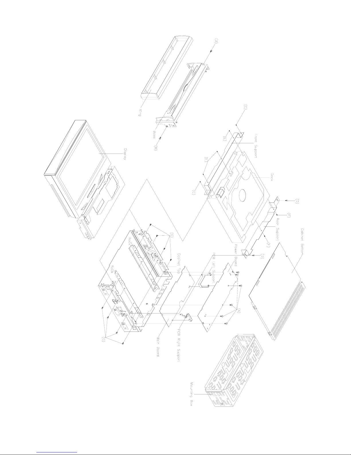
DISASSEMBLY INSTRUCTIONS (UNIT)
1. Using the unlock key that came with the unit or a similar tool, unlock the Mounting Box and remove toward the
rear of the unit.
2. Take out the Cabinet Bottom.
3. Remove six screws (A) from on the power board then remove the Power Board; The Left Support; The Right
Support and the Main Board.
4. Take out the Ring and remove two screws (B) from each side of the base then remove the Base.
5. Remove two screws (C) from on the front support and remove two screws (D) from the rear support.
6. Remove three screws (E) and remove the Front Support.
Remove two screws (F) and remove the Deck and the Rear Support.
7. Remove eight screws (G) from each side of the cabinet top then remove the Rock; The Display and the
Cabinet Top.
Page 4

4
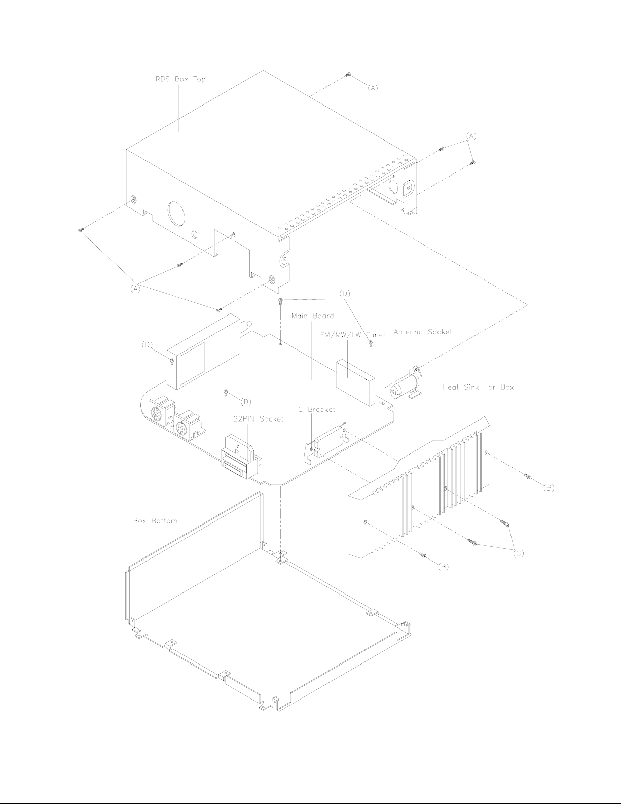
DISASSEMBLY INSTRUCTIONS (RADIO BOX)
1. Remove six screws (A) from each side of the box top the remove the Antenna Socket and the 22PIN Socket.
2. Remove the screws (B) from on the Heat Sink for Box then remove the RDS Box Top.
3. Remove two screws (C) from on the Heat Sink for Box then remove the IC Bracket and the Heat Sink For
Box.
4. Remove four screws (D) from on the main board then remove the Main Board and the Box Bottom.
Page 5
5
DISASSEMBLY DIAGRAM (UNIT)
Page 6
6
DISASSEMBLY DIAGRAM (RADIO BOX)
Page 7
7
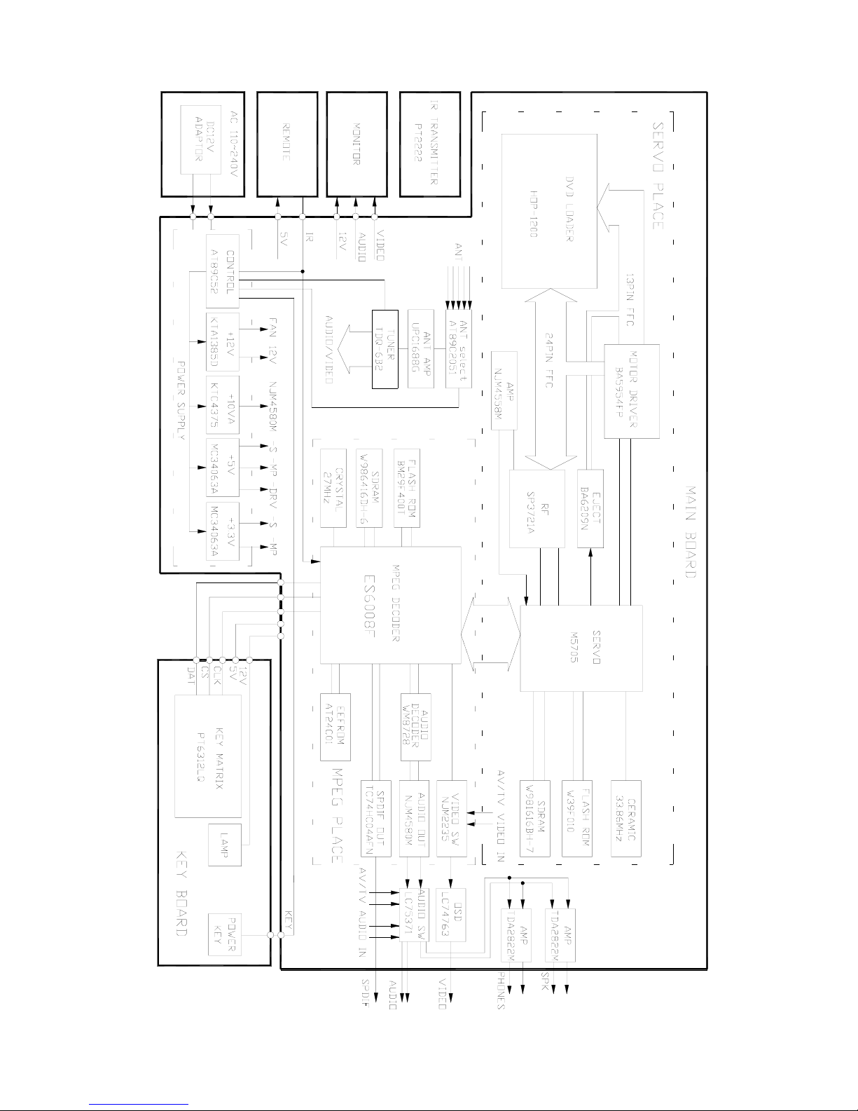
BLOCK DIAGRAM (DVD)
Page 8
8
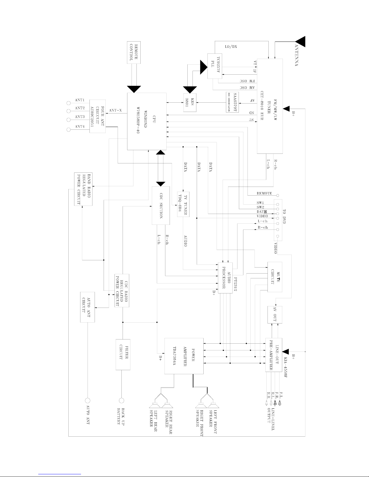
BLOCK DIAGRAM (RADIO BOX)
Page 9
9
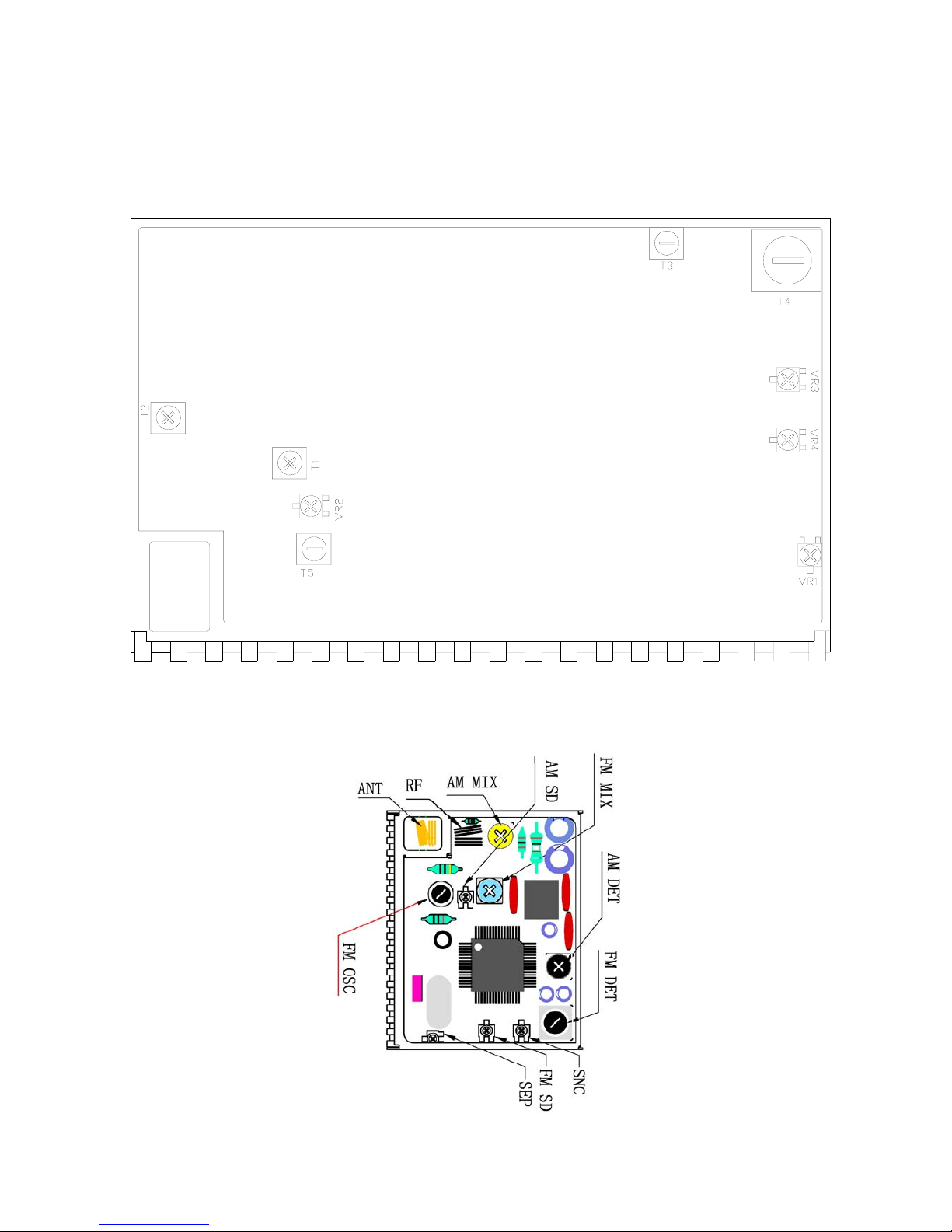
ALINGMENT LOCATIONS
LA1787 FM/MWLW TUNER
Page 10

10
ALIGNMENT PROCEDURES
FM ADJUSTMENT
Equipment Required
z AM IF/RF signal generator
z Solid-state voltmeter (SSVM)
z Regulated DC power supply
z 2-CH voltmeter
z Distortion meter
FM Alignment Using FM Signal Generator
Note: Press the radio power switch to on the radio. Signal generator output must be kept as low as possible
to avoid overload and clipping.
Step Generator
Coupling
Generator Display
Setting
Adjustment Remarks
Stereo
Separation
Signal
Generator
to antenna
receptacle
98.1 MHz
Int. 1 kHz
Dev. 75 kHz
L+R = 90 %
pilot = 10 %
98.1 MHz VR1
Adjust AF
output power
at maximum
separating
more than 30 dB
FM SNC
Adjustment
98.1 MHz
Dev. 75 kHz
L+R=90 %
Int. 1 kHz
60dBµV output
98.1 MHz
@ 40 dBµ
98.1 MHz VR3
Stereo Separation
25 dB (±5 dB)
STOP
SENS.
Signal Generator
to antenna
receptacle
98.1 MHz
Mod. 1kHz
Dev 75kHz
98.1 MHz
VR4
Adjust AF to stop
station.
Note: The tuner module is well-adjust and adjustment is not recommended.
Page 11

11
AM ADJUSTMENT
Equipment Required
z MW IF/RF signal generator
z Solid-state voltmeter (SSVM)
z Regulated DC power supply
z 2-CH voltmeter
z Distortion meter
MW Alignment Using AM Signal Generator
Note: Press the radio power switch to on the radio. Signal generator output must be kept as low as possible
to avoid overload and clipping.
Step
Generator
Coupling
Generator
Display
Setting
Adjustment
Remarks
MW
Seek
SENS.
Signal Generator
to antenna
receptacle.
1000 kHz
Input level
25 dBµV
1000 kHz VR2 Adjust AF
Stop station.
Note: The tuner module is well-adjust and adjustment is not recommended.
Page 12
12
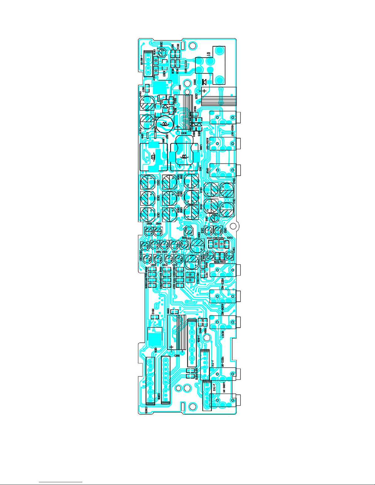
PRINTED CIRCUIT BOARDS
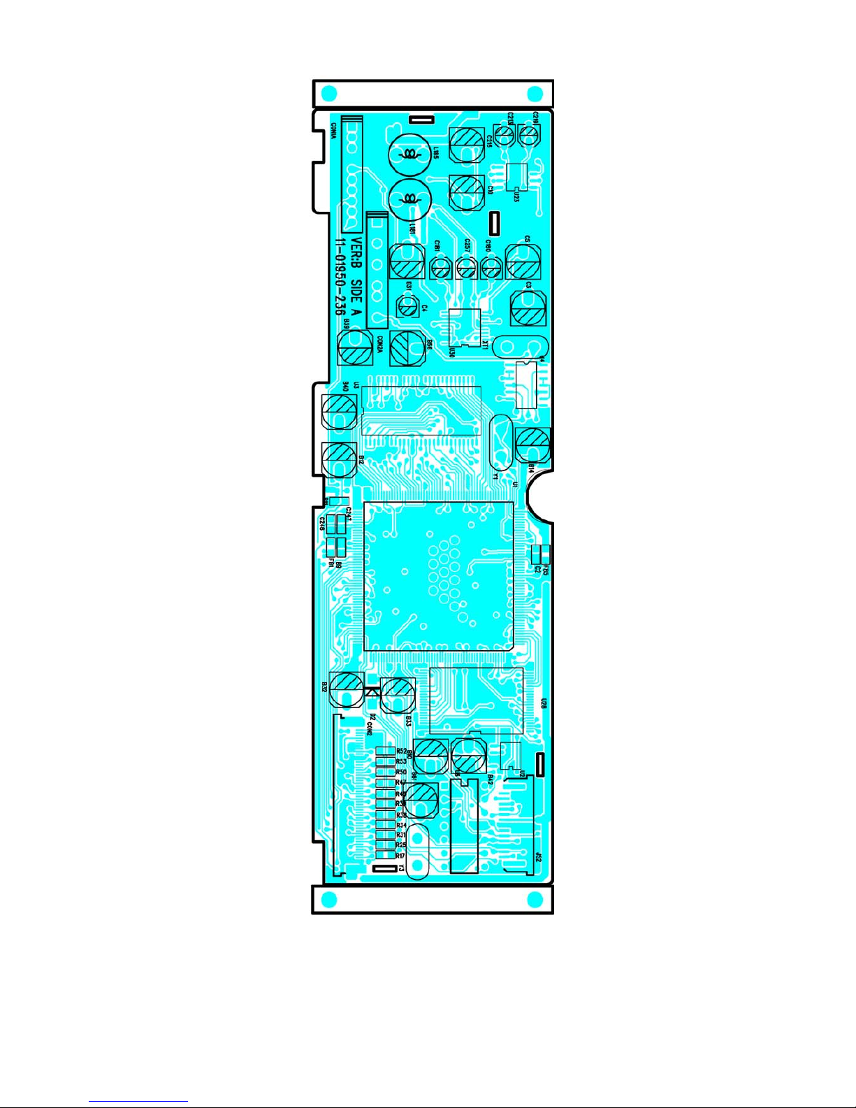
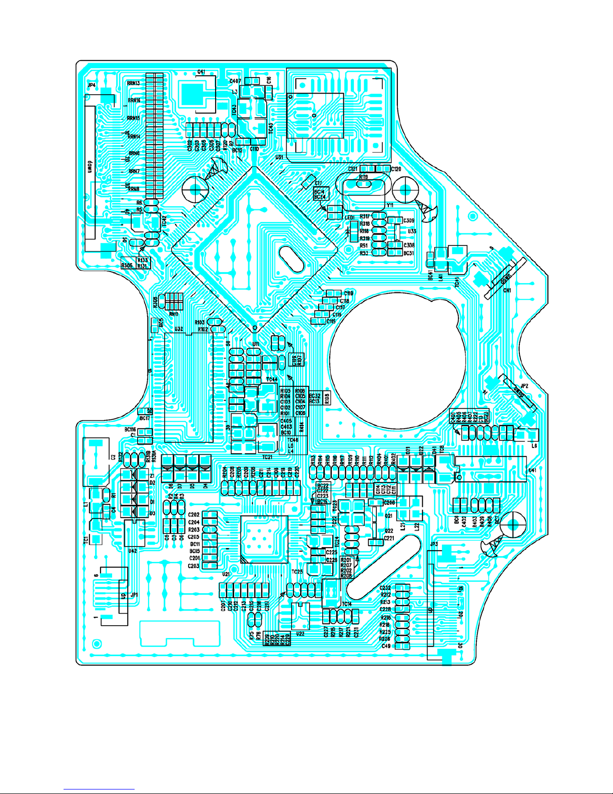
MAIN BOARD
TOP VIEW
Page 13
13
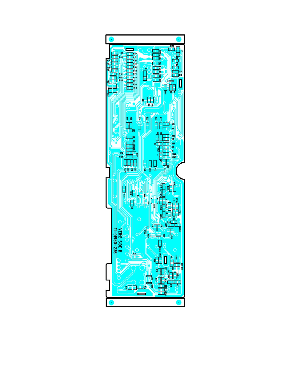
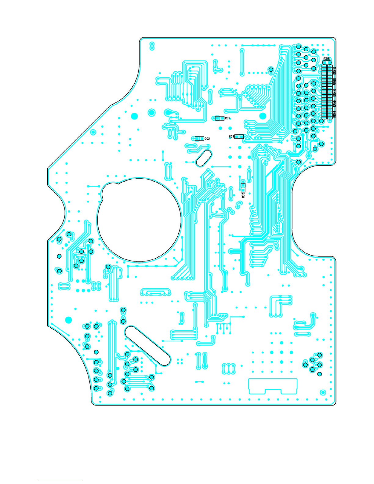
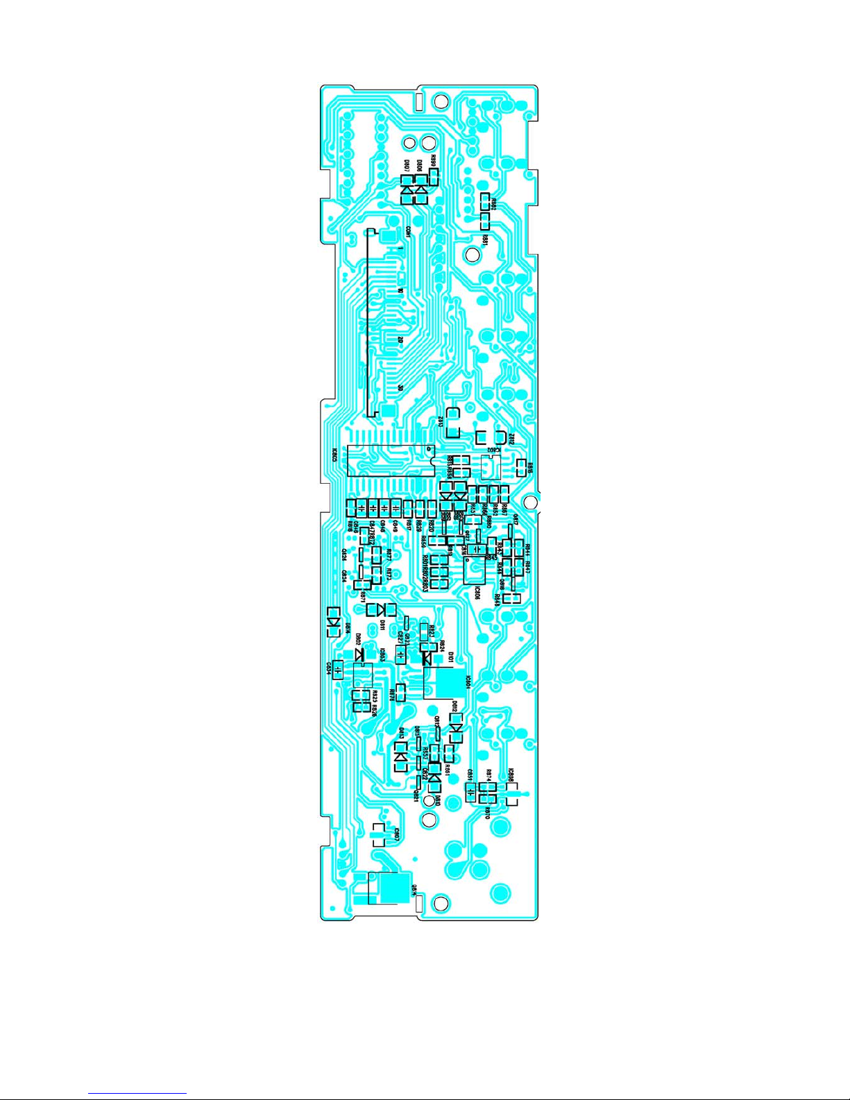
MAIN BOARD
BOTTOM VIEW
Page 14
14
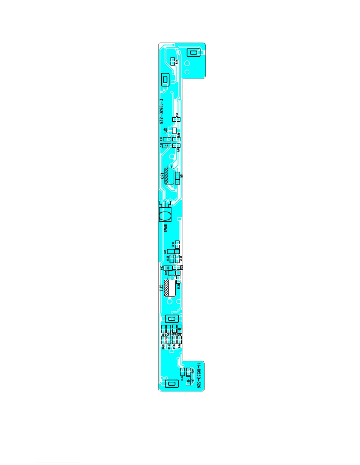
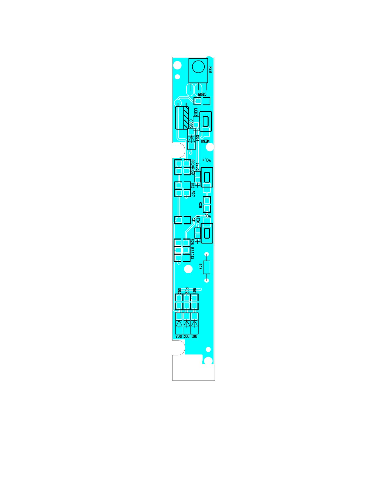
KEY BOARD
TOP VIEW
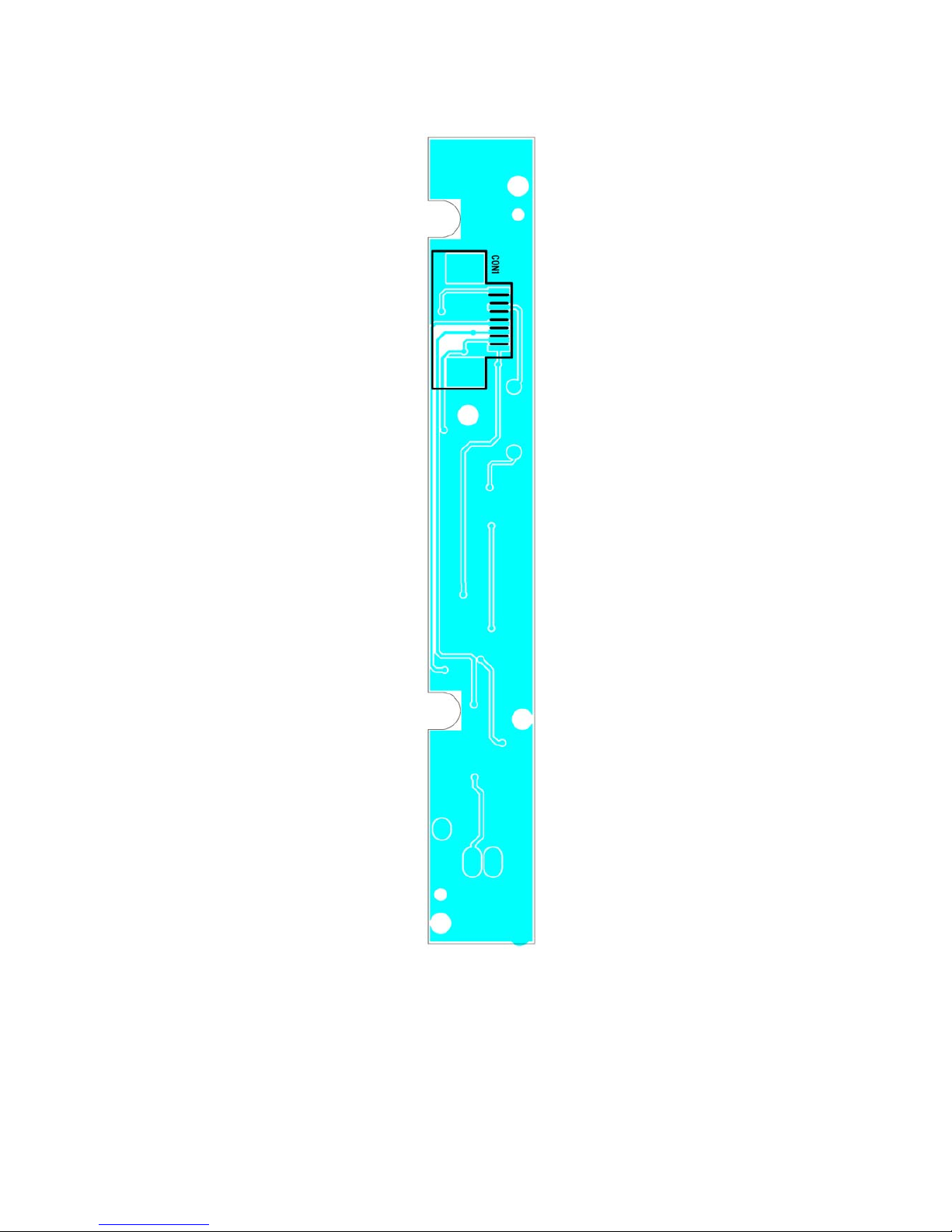
Page 15

15
KEY BOARD
BOTTOM VIEW
Page 16
16
MONITOR KEY BOARD
TOP VIEW
Page 17
17
MONITOR KEY BOARD
BOTTOM VIEW
Page 18
18
CD SERVO BOARD
TOP VIEW
Page 19
19
CD SERVO BOARD
BOTTOM VIEW
Page 20
20
POWER BOARD
TOP VIEW
Page 21
21
POWER BOARD
BOTTOM VIEW
Page 22
22
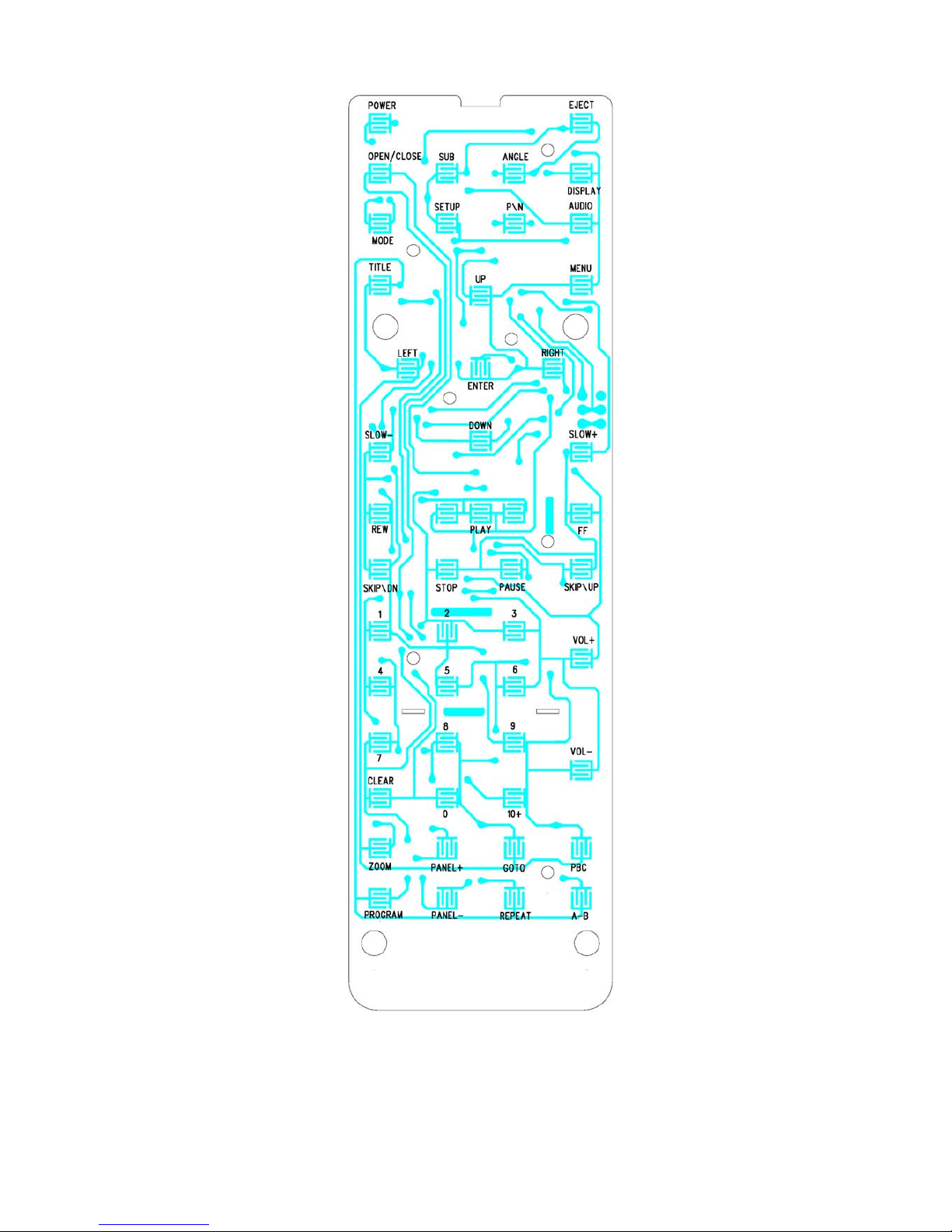
REMOTE BOARD
TOP VIEW
Page 23

23
REMOTE BOARD
BOTTOM VIEW
Page 24

24
DISPLAY BOARD
TOP VIEW
Page 25

25
DISPLAY BOARD
BOTTOM VIEW
Page 26

26
MOTOR CONTROL BOARD
TOP VIEW
Page 27

27
MOTOR CONTROL BOARD
BOTTOM VIEW
Page 28

28
TRAVEL CONTROL BOARD
Page 29

29
RADIO BOX BOARD
TOP VIEW
Page 30

30
RADIO BOX BOARD
BOTTOM VIEW
Page 31

31
EXPLODED VIEW
DISPLAY
Page 32

32
EXPLODED VIEW PARTS LIST
DISPLAY
Ref. No. Description RS Part No. Mfr’s Part No.
1
2
3
4
5
6
7
8
9
10
11
12
13
14
15
16
17
18
19
20
21
22
23
24
25
26
27
28
29
30
31
32
33
34
35
36
37
38
39
40
TFT. Cabinet Top (S. OP1304+1203) RDS W/O Brand
TFT LCD PW065XS1 PVI
TFT Fiber Sheet
Display Board
TFT Bracket COG
Cover Bottom (S. OPC1203)
Front Lens (S. OP1203/Grey426) W/O Brand
Panel Top (S. OPC1203)
Monitor Key Board
PICT Knob (L-Up) (S. OPC0000)
PC Sheet
VOL Knob (E-Silver)
VOL Back Light
Sensor Lens 2 For 1953 TFT
GEAR B (7)
Support Plate 1.2MM
Rotate Support
Move Support
Left Support
Right Support
Rotate Plate
Rotate Support Cover
Synchrony Shaft
Synch-Gear A
Motor Control Board
Protect Block
Left Motor Support ASS’Y
Motor Sheet
Right Motor Support ASS’Y
Gear Support ASS’Y
Gear A (4)
Gear A (3)
Gear A (2)
Worm Wheel B
Washer Sheet
Spring For Worm
Worm Wheel A
Gear Shaft B
Gear B (5)
Gear B (1)
51-D9522-83Y
27-01341-01
35-16901-00
11-01955-929
61-C9502-01
51-B9524-80N
33-D9533-81Y
52-D9525-80
11-01953-305
52-D9527-01
43-D9501-00
52-D9523-90E
52-D9530-00W
53-D9535-00
34-16908-01
39-C9501-00
39-16906-01
39-16905-02
52-16941-01
52-16942-01
52-B9524-00
39-B9501-00
34-16901-00
34-16912-00
11-01950-426
52-16940-00
39-16901-00
39-16912-00
39-16903-00
39-16902-00
52-16954-00
52-16948-00
52-16953-00
52-16959-00
35-16905-00
36-16903-01
52-16958-00
34-16902-00
34-16911-00
52-16949-00
Page 33

33
Ref. No. Description RS Part No. Mfr’s Part No.
41
42
43
44
45
46
47
48
49
50
51
52
53
54
55
56
57
58
59
60
Gear B (3)
Gear A (1)
Motor PWN10EA10C
Rotate Screw M3.5 BH/MS
Panel Spring (R)
Gear B (6)
Gear Support
Rotate Shaft
Bush B
Spring For Move Sup
Bush A
Left Slide Lock ASS’Y
Dial Spring Ø4X8X0.4 DWG-29
Right Slide Lock ASS’Y
Screw Ø2.0X2.0 KH/MS
Screw Ø2.0X2.0 BH/MS
Screw Ø2X3 CH/MS BLACK
Screw Ø2.6X6 PH/MS
Screw Ø2.6X4 BH/MS
Screw Ø2X8 PA/ST
52-16950-00
52-16947-00
97-01300-03
40-16901-00
36-16906-00
34-16907-00
39-16904-00
34-16903-00
34-16904-00
36-16901-00
34-16905-00
39-16908-00
36-00002-00
39-16909-00
40-12002-02
40-62002-01
40-12003-09H
40-02606-00
40-02604-01
40-12008-10
Page 34

34
EXPLODED VIEW (UNIT)
Page 35

35
EXPLODED VIEW PARTS LIST
UNIT
Ref. No. Description RS Part No. Mfr’s Part No.
1
2
3
4
5
6
7
8
9
10
11
12
13
14
15
16
17
18
19
20
21
22
23
24
25
26
27
28
29
30
31
Display
Ring (S. OP1203)
Panel Base (S. OPC1203/Gear426)
DVD MECH THIN Socket Type (HPD-60)
PC Sheet For Deck
Cabinet Bottom
Main Fiber
Cabinet Top W/RDS BOX
Mounting Box 60C
Door Sheet
Shade
Key Board
PWR Knob (L-Up) (E-Silver)
EJ/OPEN Knob (L-Up) (E-Silver)
PC Sheet
Sensor Lens 1 For 1953 Base
CD Back Light
Reset Knob (S. OPC1203)
Front Support
Rear Support
Power Board
Main Board
PCB Left Support
PCB Right Support
Spring Washer M5
Screw M5 (Rear Cabinet)
Rock
Motor Control Board
Screw Ø2.0X2.0X BH/MS
Screw Ø2X5 BH/ST Black
Screw Ø2.6X4 BH/MS
51-16924-80N
51-D9521-81Y
94-17820-00
43-B9504-00
61-B9501-00
35-B9501-00
61-B9513-01
61-02905-00
43-B9501-00
81-69005-02
11-19530-326
52-D9528-91E
52-D9526-91E
43-D9502-00
53-D9534-00
52-D9529-00W
52-D9524-80
39-B9502-00
39-B9503-00
11-19510-567
11-01950-237
39-B9504-00
39-B9505-00
35-50001-00
34-14461-00
39-16911-00
11-01950-446
40-62002-01
40-12005-06
40-02604-01
Page 36

36
EXPLODED VIEW
RADIO BOX
Page 37

37
EXPLODED VIEW PARTS LIST
RADIO BOX
Ref. No. Description RS Part No. Mfr’s Part No.
1
2
3
4
5
6
7
8
9
10
11
12
13
14
RDS Box Top (S. OPC0000) DVD195 W/O CDC
Box Bottom (S. OPC0000)
Heat Sink For Box
Main Board
LA1787 FM/MW/LW CET-8010 EUR V-Type
TV Tuner TDQ-6B2 (PAL B/G) Stand Type
IC Bracket (7560)
22PIN Socket (B+GND PIN=1.0X1.0MM)
13P DIN Socket Black
8P DIN Socket SKDS-08-02
Antenna Socket J-020-03 SINGL. Hole
Screw Ø2.6X4 BH/MS
Screw Ø2.6X6 PH/ST
Screw Ø3X14 PH/MS
61-B9512-31W
61-B9506-30
61-B9508-00
11-01956-026
29-17870-06
29-00185-01
39-A8013-00
25-F1141-22
25-00900-01
25-D0802-00
39-00017-02
40-02604-01
40-02606-05
40-03014-00
Page 38

38
SCHEMATIC DIAGRAM (MAIN BOARD) (MPEG)
Page 39

39
SCHEMATIC DIAGRAM (MPEG-POWER)
Page 40

40
SCHEMATIC DIAGRAM (MPEG-IN/OUT)
Page 41

41
SCHEMATIC DIAGRAM (POWER BOARD) (POWER)
Page 42

42
SCHEMATIC DIAGRAM (INTERFACE)
Page 43

43
SCHEMATIC DIAGRAM (KEY BOARD)
Page 44

44
SCHEMATIC DIAGRAM (SERVO BOARD) (SERVO)
Page 45

45
SCHEMATIC DIAGRAM (ATAPI)
Page 46

46
SCHEMATIC DIAGRAM (REMOTE BOARD)
Page 47

47
SCHEMATIC DIAGRAM (DISPLAY BOARD) (DRIVER)
Page 48

48
SCHEMATIC DIAGRAM (DISPLAY BOARD) (MCU)
Page 49

49
SCHEMATIC DIAGRAM (MOTOR CONTROL BOARD)
Page 50

50
SCHEMATIC DIAGRAM (RADIO BOX)
Page 51

51
ELECTRICAL PARTS LIST
Ref. No. Parts No. Description Q’ty
PC BOARD ASSY, MAIN BOARD
Q24/6
Q13,22
Q1
D2
D1,4
U2
U23
U1
U3
U4
U30
U28
U6
Y1
Y3
B1~3,6~9,11/3/5~30/4~8,41/5,59,C1
,6,9,11/2/9,230/2,246/7,256
C248/9
C184/8
C185,190
C20/1
C196/7
C8,23
C7
C4,180/1,213/9,257
C3,5,10,215
B10/2/4,31~3/9,40/2,56,61
FB2,7
R61
R19
R11/2/6
R14/5,29,156
R54,187/8
R43,56/7,304
R20/4
R178
R22/8,186/9
R296
R9,13/7/8,23/5/6,30~9,48~50
R55
R21/7
01-00106-00
01-00231-00
01-03265-00
02-04001-01
02-04148-02
03-02401-00
03-04580-00
03-06008-00
03-06146-00
03-07404-01
03-08728-00
03-29400-20
03-78153-03
04-00270-00
04-00400-02
05-63104-02
05-63200-00
05-63221-00
05-63222-01
05-63330-00
05-63471-00
05-63473-01
05-63474-02
06-16106-54
06-16107-54
06-63227-54
07-05000-54
07-63000-00
07-63100-00
07-63101-00
07-63102-00
07-63103-00
07-63104-00
07-63113-00
07-63151-00
07-63203-00
07-63271-00
07-63330-00
07-63330-04
07-63332-00
KRA106S (SOT-23)
KRC231S (SOT-23)
KTC3265-Y (SOT-23)
CHIP IN4001 (SOD-106)
DIODE CHIP RLS4148 1206 ROHM
EEPROM (FLAT PACK) 24C01
NJM4580M (SOP-8PIN)
ES6008 (PQFP-208PIN)
W986416DH-6 (TSOP II-54PIN)
TC74HCU04FAN (SOL-14PON)
WM8728 (SSOP-20PIN)
AM29LV400BT-90 DVD195/1951
IC EM78P153SP DVD195 (EE1F/016F)
CRYSTAL 27M (HC-49/US)
CERAMIC RESONATOR 4MHZ
CHIP CAP 0.1µF ±20% Y5V 0603 SMT
CHIP CAP 20P ±5% NPO 0603 SMT
CHIP CAP 220PF ±5% NPO 0603 SMT
CHIP CAP 2200PF ±10% X7R 0603 SMT
CHIP CAP 33PF ±5% NPO 0603 SMT
CHIP CAP 470PF ±5% NPO 0603 SMT
CHIP 0.047µF ±10% X7R 0603 SMT
CHIP 0.47µF ±20% X7R 0603 SMT
E. CAP CHIP 10µ/16V Ø4X5.5
E. CAP CHIP 100µ/16V Ø6.3X5.5
E. CAP CHIP 220µ/6.3V Ø6.3X5
CHIP RES 0Ω 1/10W
CHIP RES 0Ω ±5% 0603 SMT
CHIP RES 10Ω ±5% 0603 SMT
CHIP RES 100Ω ±5% 0603 SMT
CHIP RES 1kΩ ±5% 0603 SMT
CHIP RES 10kΩ ±5% 0603 SMT
CHIP RES 100kΩ ±5% 0603 SMT
CHIP RES 11kΩ ±5% 0603 SMT
CHIP RES 150Ω ±5% 0603 SMT
CHIP RES 20kΩ ±5% 0603 SMT
CHIP RES 270Ω ±5% 0603 SMT
CHIP RES 33Ω ±5% 0603 SMT
CHIP CN34JT 33Ω (0603X4 SMT)
CHIP RES 3.3kΩ ±5% 0603 SMT
2
2
1
1
2
1
1
1
1
1
1
1
1
1
1
44
2
2
2
2
2
2
1
6
4
11
2
1
1
3
4
3
4
2
1
4
1
21
1
2
Page 52

52
ELECTRICAL PARTS LIST - CONTINUED
Ref. No. Parts No. Description Q’ty
R1,3~7,10,52/8,299
R64,179
L12
FB1/3~6
L185
L181
R40/2/5~7,51/3/9
07-63472-00
07-63750-00
09-00270-00
09-00601-00
09-03315-00
09-10190-00
09-11470-00
11-01950-237
12-00162-00
CHIP RES 4.7kΩ ±5% 0603 SMT
CHIP RES 75Ω ±5% 0603 SMT
CHIP SGMI1608M2R7KT
CHIP BGH2012B601LB
SL0805-3R3M1R5
SL0805-101KR90
EMIFIL (SMD) BLM11B470SB
PCB DVD195 MPEG BOARD F/S 146X49.5X1.2
50PIN FPC P0.5/0.3
10
2
1
5
1
1
8
1
1
PC BOARD ASSY, FM TUNER BOARD
LED1~3
C12/3
C11,CR05
CR03
R04
RR04
R23/7
R26/8
R139
MENU VOL+/-
CON01
REM
02-01112-00F
05-63103-01
05-63104-01
06-16475-02
07-05121-00
07-63000-00
07-63102-00
07-63152-00
07-63821-00
11-01953-305
16-01140-04A
25-00101-08
25-16901-08
29-01201-00
SMD LED PG1112H GREEN “STANLEY”
CHIP 0.01µF ±10% X7R 0603 SMT
CHIP 0.1µF ±10% X7R 0603 SMT
E. CAP 4.7µF 16V (Ø3.5X5MM)
RES 120Ω 1/4W
CHIP RES 0Ω ±5% 0603 SMT
CHIP RES 1kΩ ±5% 0603 SMT
CHIP RES 1.5kΩ ±5% 0603 SMT
CHIP RES 820Ω ±5% 0603 SMT
KB (MYSON) FOR DVD1953 D/S 118X13X1.0
TACT SW. KPS-1107SW TAPPING
8PIN 1.0MM WIRE FFC 50MM
8PIN 1.0MM SMT CON
IR RECEIVER GP1UM261XK (SHARP)
3
2
2
1
1
1
2
2
1
1
3
1
1
1
PC BOARD ASSY, KEY BOARD
QF1
LED
POWER LED
DF1
ZD2
UF1
CF3/5
CF6~8
CF4
CF2
CF1
RF17
RF1
RF4,12~4
RF2,3
RF10/1
RF5
01-03265-00
02-01112-00F
02-01112-02F
02-04148-02
02-50047-01
03-06312-00
05-03101-10
05-03104-10F
05-03470-10
06-10107-01
06-16475-02
07-63000-00
07-63100-00
07-63102-00
07-63103-00
07-63151-00
07-63333-00
KTC3265-Y (SOT-23)
SMD LED PG1112H GREEN “STANLEY”
SMD LED BR1112H RED “STANLEY”
DIO CHIP RLS4148 1206 ROHM
CHIP ZENER DIODE 4.7V (LL-34)
IC PT6312LQ ANGUS
CHIP CAP CM21CH101K25AT
CHIP CAP 0.1µF 25V Z5U ±20%
CHIP CAP CM21CH47K50KT
E. CAP 100µF 10V (Ø5X7MM MINI)
E. CAP 4.7µF 16V (Ø3.5X5MM)
CHIP RES 0Ω ±5% 0603 SMT
CHIP RES. 10Ω ±5% 0603 SMT
CHIP RES. 1kΩ ±5% 0603 SMT
CHIP RES. 10kΩ ±5% 0603 SMT
CHIP RES. 150Ω ±5% 0603 SMT
CHIP RES. 33kΩ ±5% 0603 SMT
1
2
1
1
1
1
2
3
1
1
1
1
1
4
2
2
1
Page 53

53
ELECTRICAL PARTS LIST - CONTINUED
Ref. No. Parts No. Description Q’ty
RF9
RF6,8
RF16
RESET, EJECT, OPEN, POWER
REM1
07-63471-00
07-63472-00
07-63681-00
11-19530-326
16-01140-04A
25-19500-12
29-01201-00
CHIP RES. 470Ω ±5% 0603 SMT
CHIP RES. 4.7kΩ ±5% 0603 SMT
CHIP RES. 680Ω ±5% 0603 SMT
PCB DVD1953 KB D/S 161X21.2X1.2MM
TACT SW KPS-1107SW TAPPING
DVD195 12PIN RIBBOM WIRE 110MM (1.5MM)
IR RECEIVER GP1UM261XK (SHARP)
1
2
1
1
4
1
1
PC BOARD ASSY, SDK/CD SERVO BOARD
Q21/2
D1~5,21/2,41
Z1
Q41
U32
U21
U22
U33
U11
U41
U42
U31
Y11
TC1
C3,5~7,302
C217
C108,117/8,206,218,221/3
CBC1,3,4,13,24,31,40/9,104/6/7,110
/5/6/9,201~5,210/9,225/6/8/9,403~
5/7
C120/1
C220
C308
C208/9,211,227
C105
C113/4
C222,401
C102,112,214
C111,231,309
C103
C207,212/3/5/6
C109
C2
TC22~5,46
01-01298-00
02-04148-02
02-50062-54
03-01117-01
03-01616-00
03-03721-01
03-04580-00
03-04743-00
03-05706-00
03-05918-00
03-06289-00
03-39010-01
04-03386-00
05-25106-10
05-63100-00
05-63101-00W
05-63102-00
05-63104-01
05-63120-00
05-63151-00
05-63224-01
05-63330-00
05-63470-00
05-63471-00
05-63472-01
05-63473-01
05-63474-00
05-63561-00
05-63681-00
05-63682-01
06-16226-55
06-63106-55
KTA1298 (SOT-23)
DIO CHIP RLS4148 1206 ROHM
ZENER DIODE SMD 6.2V (LLDS) 1206
FIX 3.3V VOL REGVLATER AMS1117-3.3
W981616BH-7 (TSOP II-50PIN)
IC SP3721A (HIGH TEMP) (PQFP-64PIN)
NJM4580M (SOP-8PIN)
IC BD4743G (SMP5) ROHM
IC M5706 (PQFP-176PIN)
BA5819FP-Y HSOP-25PIN
BA6289F (SOP8)
IC SST39SF010 (TSOP-32PIN)
CERAMIC ZTA33.86MX
TAN CAP CHIP 10µ 25V 1206 SMT
CHIP CAP 10PF ±5% NPO 0603 SMT
CHIP CAP 100PF ±5% NPO 0603 SMT
CHIP CAP 1000PF ±5% NPO 0603 SMT
CHIP 0.1µF ±10% X7R 0603 SMT
CHIP CAP 12PF ±5% NPO 0603 SMT
CHIP CAP 150PF ±5% NPO 0603 SMT
CHIP 0.22µF ±10% X7R 0603 SMT
CHIP CAP 33PF ±5% NPO 0603 SMT
CHIP CAP 47PF ±5% NPO 0603 SMT
CHIP 470PF ±5% NPO 0603 SMT
CHIP 4700PF ±10% X7R 0603 SMT
CHIP 0.047µF ±10% X7R 0603 SMT
CHIP CAP 0.47µF Y5V +80%
CHIP 560PF ±5% NPO 0603 SMT
CHIP 680PF ±5% NPO 0603 SMT
CHIP 6800PF ±10% X7R 0603 SMT
TAN CAP 22µ/16V SMD (3.5X2.8X2.0MM)
TAN CAP 10µ/6.3V SMD (3.5X2.8X2.0MM)
2
8
1
1
1
1
1
1
1
1
1
1
1
1
5
1
7
50
2
1
1
4
1
2
2
3
3
1
5
1
1
5
Page 54

54
ELECTRICAL PARTS LIST - CONTINUED
Ref. No. Parts No. Description Q’ty
TC8,14,21,41~5
R414
R132,401/2,131A/B
R120,207
R5,6
RRN6~8,13~6
R1,317
R104,112/8,209,210/7,305,315,404
RN4,9~12
R102,119,215
R101
R406
R214
R208
R107
R409
R216/8,225/6
R114,201/4~6,308,407
RN11
R109~111/5,405
R403/8
R2~4,106,116,318
R113
R221
R105,117,202
R108
R103
R203,220
L21/2
L1,3~6,41
JP2
JP4
JP1
JP3
06-63107-55
07-05033-54
07-63000-00
07-63100-00
07-63101-00
07-63101-04
07-63102-00
07-63103-00
07-63103-04
07-63104-00
07-63122-00
07-63123-00
07-63152-00
07-63153-00
07-63203-00
07-63223-00
07-63242-00
07-63330-00
07-63330-04
07-63332-00
07-63333-00
07-63472-00
07-63473-00
07-63474-00
07-63512-00
07-63513-00
07-63563-00
07-63822-01
09-00100-54
09-31601-00
11-01004-227
25-50501-14
25-50501-50
25-50502-06
25-50502-30
TAN CAP 100µ/6.3V SMD (3.2X1.6X2.0MM)
CHIP RES 3.3Ω SMD 0805
CHIP RES 0Ω ±5% 0603 SMT
CHIP RES 10Ω ±5% 0603 SMT
CHIP RES 100Ω ±5% 0603 SMT
CHIP CN34JT 100Ω (0603X4 SMT)
CHIP RES 1kΩ ±5% 0603 SMT
CHIP RES 10kΩ ±5% 0603 SMT
CHIP CN34JT 10kΩ (0603X4 SMT)
CHIP RES 100kΩ ±5% 0603 SMT
CHIP RES 1.2kΩ ±5% 0603 SMT
CHIP RES 12kΩ ±5% 0603 SMT
CHIP RES 1.5kΩ ±5% 0603 SMT
CHIP RES 15kΩ ±5% 0603 SMT
CHIP RES 20kΩ ±5% 0603 SMT
CHIP RES 22kΩ ±5% 0603 SMT
CHIP RES 2.4kΩ ±5% 0603 SMT
CHIP RES 33Ω ±5% 0603 SMT
CHIP CN34JT 33Ω (0603X4 SMT)
CHIP RES 3.3kΩ ±5% 0603 SMT
CHIP RES 33kΩ ±5% 0603 SMT
CHIP RES 4.7kΩ ±5% 0603 SMT
CHIP RES 47kΩ ±5% 0603 SMT
CHIP RES 470kΩ ±5% 0603 SMT
CHIP RES 5.1kΩ ±5% 0603 SMT
CHIP RES 51kΩ ±5% 0603 SMT
CHIP RES 56kΩ ±5% 0603 SMT
CHIP RES 8.2kΩ ±1% 0603 SMT
INDUCTOR 10µH SMD 0805
EMIFIL (SMD) BLM31P601SG
DVD-1004 SB D/S 130X90X0.8MM
14P 0.5MM SMD SOCKET DOWN CONTACT
50P SOCKET 50002A-50T1-B SUYIN
6P 1MM SMD SOCKET UPPER CONTACT
30P 0.5MM SMD SOCKET UPPER CONTACT
8
1
5
2
2
7
2
11
5
3
1
1
1
1
1
1
4
7
1
5
2
6
1
1
3
1
1
2
2
6
1
1
1
1
1
PC BOARD ASSY, POWER BOARD
Q805/9,827
Q810/3
Q820/5
Q817/8
Q807,814/6
01-00106-00
01-00106-10
01-00231-00
01-01298-00
01-01385-00
KRA106S (SOT-23)
KRC106S (SOT-23)
KRC231S (SOT-23)
KTA1298 (SOT-23)
KTA1385D-Y (DPAK)
3
2
2
2
3
Page 55

55
ELECTRICAL PARTS LIST - CONTINUED
Ref. No. Parts No. Description Q’ty
D817
D804~9,814/6
D801~3
Z813
Z812
Z811
IC804
IC806
IC1
IC802
IC801/7/8
IC803
C853/4
C827
C816,837/9,851
C834
C801/2/7/8,811~5/7
C809,835/8,840/2/5
C850/2/5
C810,826,836
C803/6,819,828~33,841/3
R818/9,853,866/7,881/2,890
R819,878
R843/6
R822,834/5/7,842,851/2,876
R824
R801
R2,845/8,856
R821,836,874,896/7
R826
R844/7
R880
R854/5,870
R823/5
R804/7~9
R1,875
R849,850/8/9
R827
R805,812~4
R802/3,892~5
R828
L887
02-04001-01
02-04148-02
02-05819-02
02-50051-03
02-50091-01
02-50100-02
03-00141-00
03-02235-00
03-04052-03
03-04580-00
03-07805-02
03-34063-01
05-63101-00
05-63102-01
05-63104-02
05-63470-00
06-16106-54
06-16107-54
06-16107-55
06-16108-02
06-63227-54
07-63000-00
07-63100-00
07-63101-00
07-63103-00
07-63122-01
07-63151-00
07-63221-00
07-63222-00
07-63222-01
07-63223-00
07-33331-00
07-63332-00
07-63362-01
07-63392-00
07-63471-00
07-63473-00
07-63512-00
07-63681-00
07-63750-00
07-63821-00
09-03315-00
CHIP IN4001 (SOD-106)
DIO CHIP RLS4148 1206 ROHM
CHIP IN5819 (SOD-106)
CHIP ZENER DIODE 5.1V ±5% (LL-34)
CHIP ZENER DIODE 9.1V ±5% 0.5W LL-34
CHIP ZENER DIODE 10V (LL-34)
IC PQICZ41H SMD SHARP
IC CHIP NJM2235M JRC
I.C. CHIP BU4052BCF ROHM
NJM4580M (SOP-8PIN)
KIA 78L05F (SOT-89)
MC34063A (SOP-8PIN)
CHIP 100PF ±5% NPO 0603 SMT
CHIP 1000PF ±10% X7R 0603 SMT
CHIP CAP 0.1µF ±20% Y5V 0603 SMT
CHIP CAP 47PF ±5% NPO 0603 SMT
E. CAP CHIP 10µ/16V Ø4X5.5
E. CAP CHIP 100µ/16V Ø6.3X5.5
TAN CAP 100µ/16V SMD (7.3X4.3X2.8MM)
E. CAP 1000µ 16V Ø8MM
E. CAP CHIP 220µ/6.3V Ø6.3X5
CHIP RES 0Ω ±5% 0603 SMT
CHIP RES 10Ω ±5% 0603 SMT
CHIP RES 100Ω ±5% 0603 SMT
CHIP RES 10kΩ ±5% 0603 SMT
CHIP RES 1.2kΩ ±1% 0603 SMT
CHIP RES 150Ω ±5% 0603 SMT
CHIP RES 220Ω ±5% 0603 SMT
CHIP RES 2.2kΩ ±5% 0603 SMT
CHIP RES 2.2kΩ ±1% 0603 SMT
CHIP RES 22kΩ ±5% 0603 SMT
CHIP RES 330Ω ±5% 0603 SMT
CHIP RES 3.3kΩ ±5% 0603 SMT
CHIP RES 3.6kΩ ±1% 0603 SMT
CHIP RES 3.9kΩ ±5% 0603 SMT
CHIP RES 470Ω ±5% 0603 SMT
CHIP RES 47kΩ ±5% 0603 SMT
CHIP RES 5.1kΩ
CHIP RES 680Ω ±5% 0603 SMT
CHIP RES 75Ω ±5% 0603 SMT
CHIP RES 8200Ω ±5% 0603 SMT
SL0805-3R3M1R5
1
8
3
1
1
1
1
1
1
1
3
1
2
1
4
1
11
6
3
3
11
8
2
2
8
1
1
4
5
1
2
1
3
2
4
2
4
1
4
6
1
1
Page 56

56
ELECTRICAL PARTS LIST - CONTINUED
Ref. No. Parts No. Description Q’ty
L883/6
L888
REPEAT
AUDIO OUT, AUDIO IN2
VIDEO OUT, VIDEO IN2
SPDIF
CON1B,CON2B
09-22113-00
09-70275-00
11-01950-387
11-19510-567
16-00035-04
16-00035-10
16-00035-20
16-00035-30
25-05569-01
25-19510-32
25-24184-05
25-34184-10C
CDRH125-221M1R3
CHOKE 275UH JCI-519-Ø6X8
32PIN FPC P1.0/0.4
DVD1951 POWER BOARD F/S 173X45X1.2MM
Ø3.5MM JACK (4PIN) W/SW
Ø3.5MM JACK (4PIN) BLACK
Ø3.5MM JACK (4PIN) YELLOW
Ø3.5MM JACK (4PIN) ORANGE
4PIN 5569-NA1 SKT (DVD120)
1.0MM PITCA FFC/FPC CONNECT OF P/A SMT
EAFER FOR 5PIN JST2.0
EAFER FOR 10PIN JST2.0
2
1
1
1
1
2
2
1
1
1
1
2
PC BOARD ASSY, REMOTE BOARD
Q1
D4,8,9
IC2
IC1
C1,2,4,6
C3,5
R1
R17/9
X1,XT1
01-01781-18
02-00120-00
02-04148-02
03-00101-00
03-02222-00
05-63121-00
06-06476-02
07-05022-54
07-63470-00
09-50455-05
11-01950-507
TR. 2SD1781K-R “ROHM”
IR EMITIER DIODE MIE-544A4
DIO CHIP RLS4148 1206 ROHM
IC S0101 (SGNEC)
IC PT2222-001 SOP ANGUS
CHIP 120PF ±5% NPO 0603 SMT
E. CAP 47µF 6.3V (Ø5X5MM)
CHIP RES. 2.2Ω 1/10W
CHIP RES 47Ω ±5% 0603 SMT
CER RESONATOR CSB-455E “MURATA”
DVD195/1951 REM PCB D/S 48X160X1.2MM
1
1
3
1
1
4
2
1
2
2
1
PC BOARD ASSY, DISPLAY BOARD
Q101
Q104/7,401
Q105/6,402/3
Q108
Q102/3,801
D401
D3,4,6,7,102,801/3/4
D101/5
ZD802
ZD101
IC204
IC402
IC401
IC803
IC403
IC202,700/1
IC101
01-00197-00
01-00812-00
01-01623-00R
01-02103-00
01-04672-00
02-00335-00
02-04148-02
02-05040-00
02-50039-01
02-50182-00
03-00331-00
03-00481-00
03-01004-01
03-02408-01
03-03414-00
03-04053-01
03-09741-00
TR. SMD 2SJ197
TR. 2SA812
CHIP TR. C1623 “NEC”
TR CHIP 2SK2103 ROHM
TR. SMD 2SC4672Q
DIODE MA335 SMD PANASONIC
DIO CHIP RLS4148 1206 ROHM
DIO CHIP RB050L-40 SOD106 ROHM
CHIP ZENER DIODE 3.9V ±5% (LL-34)
CHIP ZENER DIODE 8.2V 0.5W
IC CHIP IR3Y31M SHARP
IC BU4S81 SMD ROHM
IC PVI-1004C SMD
IC AT24C08 SOIC ATMEL
IC CHIP NJM3414AM JRC
IC BU4053BF TSSOP16 ROHM
IC BA9741F SOIC16
1
3
4
1
3
1
9
2
1
1
1
1
1
1
1
3
1
Page 57

57
ELECTRICAL PARTS LIST - CONTINUED
Ref. No. Parts No. Description Q’ty
IC800
IC804
X1
X501
X502
C108,414,514/6/8
C106
C49,118,130,141,418,502,701,815/6
,892
C107
C52
C406,509
C113
C110,143,511
C1,2,4,5,7,84,109,120/1/3/4/6,250/1/
6/7,263~6,270~2/8,280/1,402/3/9,4
11/5,506~8
C105,401/7,501,513/5/7,524/5,702~
5,852,862,872,892
C147
C405
C865/6
C111
C505
C410/6
C115
C128/9,133/5/9,140/2,504
C512
C510
C114,503
C408,523
C350
C9,24
C412/3
C3,102~4,127,138,800/2
C882
C6,136/7
C116/7/9,122/5,131/2/4,269,876
R204
R2~4,6,8,10~2/5/6,20/1/3,36/7,69,11
0,126,471/2,510,VR210/5/6,RN/PR
120
03-17805-00
03-23064-01
04-00120-10
04-03579-00
04-04433-00
05-03225-10
05-04683-00
05-25106-10
05-30470-10
05-63100-00
05-63101-00
05-63102-00
05-63103-01
05-63104-01
05-63105-00
05-63151-00
05-63151-01
05-63220-00
05-63221-00
05-63224-01
05-63331-00
05-63332-01
05-63473-01
05-63474-02
05-63560-00
05-63681-00
05-63682-01
05-63820-00
05-63821-00
06-06476-54
06-16107-54
06-35106-54
06-35476-54
06-63227-54
07-05150-54
07-63000-00
07-63100-00
IC CHIP BA178M05FP ROHM
IC MTV230M64 (FOR DVD195) (YOUSHENG)
CRYSTAL 12MHZ 49U/SM 30PPM CHIP
CRYSTAL 3.579MHZ (SMD)
CRYSTAL 4.433MHZ SMD
CHIP CAP 2.2µF/25V SMD 1206
METALIZED CAP 0.068µF 63V ±5%
TAN CAP CHIP 10µ 25V 1206 SMT
CHIP CAP 47PF 3KV ±5% 4.5X2MM
CHIP 10PF ±5% NPO 0603 SMT
CHIP 100PF ±5% NPO 0603 SMT
CHIP 1000PF ±5% NPO 0603 SMT
CHIP 0.01µF ±10% X7R 0603 SMT
CHIP 0.1µF ±10% X7R 0603 SMT
CHIP CAP 105PF/25V Y5V ±20% 0603 SMT
CHIP CAP 150PF ±5% NPO 0603 SMT
CHIP CAP 150PF ±5% SL 0603 SMT NGEATIVE
CHIP 22PF ±5% NPO 0603 SMT
CHIP 220PF ±5% NPO 0603 SMT
CHIP 0.22µF ±10% X7R 0603 SMT
CHIP CAP 330PF ±5% NPO 0603 SMT
CHIP 3300F ±10% X7R 0603 SMT
CHIP 0.047µF ±10% X7R 0603 SMT
CHIP 0.47µF ±20% X7R 0603 SMT
CHIP CAP 56PF ±5% NPO 0603 SMT
CHIP 680PF ±5% NPO 0603 SMT
CHIP 6800PF ±10% X7R 0603 SMT
CHIP CAP 82PF ±5% NPO 0603 SMT
CHIP CAP 820PF ±5% NPO 0603 SMT
E. CAP CHIP 47µ/16V Ø5X5.5
E. CAP CHIP 100µ/16V Ø6.3X5.5
E. CAP CHIP 10µ/35V Ø5X5.5
E. CAP CHIP 47µ/35V Ø6.3X5
E. CAP CHIP 220µ/6.3V Ø6.3X5.5
CHIP RES 15Ω 1/10W
CHIP RES 0Ω ±5% 0603 SMT
CHIP RES 10Ω ±5% 0603 SMT
1
1
1
1
1
5
1
10
1
1
2
1
3
42
17
1
1
2
1
1
2
1
8
1
1
2
2
1
2
2
8
1
3
10
1
13
1
Page 58

58
ELECTRICAL PARTS LIST - CONTINUED
Ref. No. Parts No. Description Q’ty
R103/7,482,512,706/7,813/4
R5,101,117,163,291/3,C404,495,52
5,854,864,874,894
R111,129,181/2/4/5,402,414,466/8,4
70/5/7,481,511,849,850,895
R104,446
R505,528,832
R503
R851/6,871,891
R286,294,307
R489
R114
R449,478,480,509
R526
R447
R479
R124,515
R1,469
R105
R501
R278,297
R467
R312
R109,296/8/9,313
R504
R194,203~5,210,401/4/7,410~3/5~8
,424,430/1,453/4,465
R473
R188,290/2
R113,476
R106,130
R17,115,187,505,517/9,521,811/2,8
31,852,862,872,862,C112
R108,112/8
R875
R102,440/3~5,435/7/9,450/8/9,461/2
,474,865
R279,280/5,514/6/8,520,861
R277
R527
R502
R295,308
R802
07-63101-00
07-63102-00
07-63103-00
07-63104-00
07-63105-00
07-63106-00
07-63122-00
07-63123-00
07-63151-00
07-63152-00
07-63153-00
07-63183-00
07-63203-00
07-63204-00
07-63221-00
07-63222-00
07-63223-00
07-63271-00
07-63273-00
07-63303-00
07-63332-00
07-63333-00
07-63334-00
07-63390-00
07-63391-00
07-63392-00
07-63393-00
07-63471-00
07-63472-00
07-63473-00
07-63513-00
07-63561-00
07-63562-00
07-63683-00
07-63684-00
07-63750-00
07-63752-00
07-63820-00
CHIP RES 100Ω ±5% 0603 SMT
CHIP RES 1kΩ ±5% 0603 SMT
CHIP RES 10kΩ ±5% 0603 SMT
CHIP RES 100kΩ ±5% 0603 SMT
CHIP RES 1MΩ ±5% 0603 SMT
CHIP RES 10MΩ ±5% 0603 SMT
CHIP RES 1.2kΩ ±5% 0603 SMT
CHIP RES 12kΩ ±5% 0603 SMT
CHIP RES 150Ω ±5% 0603 SMT
CHIP RES 1.5kΩ ±5% 0603 SMT
CHIP RES 15kΩ ±5% 0603 SMT
CHIP RES 18kΩ ±5% 0603 SMT
CHIP RES 20kΩ ±5% 0603 SMT
CHIP RES 200kΩ ±5% 0603 SMT
CHIP RES 220Ω ±5% 0603 SMT
CHIP RES 2.2kΩ ±5% 0603 SMT
CHIP RES 22kΩ ±5% 0603 SMT
CHIP RES 270Ω ±5% 0603 SMT
CHIP RES 27kΩ ±5% 0603 SMT
CHIP RES 30kΩ ±5% 0603 SMT
CHIP RES 3.3kΩ ±5% 0603 SMT
CHIP RES 33kΩ ±5% 0603 SMT
CHIP RES 330kΩ
CHIP RES 39Ω ±5% 0603 SMT
CHIP RES 390Ω ±5% 0603 SMT
CHIP RES 3.9kΩ ±5% 0603 SMT
CHIP RES 39kΩ ±5% 0603 SMT
CHIP RES 470Ω ±5% 0603 SMT
CHIP RES 4.7kΩ ±5% 0603 SMT
CHIP RES 47kΩ ±5% 0603 SMT
CHIP RES 51kΩ ±5% 0603 SMT
CHIP RES 560Ω ±5% 0603 SMT
CHIP RES 5.6kΩ ±5% 0603 SMT
CHIP RES 68kΩ ±5% 0603 SMT
CHIP RES 680kΩ ±5% 0603 SMT
CHIP RES 75Ω ±5% 0603 SMT
CHIP RES 7.5kΩ ±5% 0603 SMT
CHIP RES 82Ω ±5% 0603 SMT
8
13
18
2
3
1
4
3
1
1
4
1
1
1
2
2
1
1
2
1
1
5
1
22
1
3
2
2
15
3
1
15
8
1
1
1
2
1
Page 59

59
ELECTRICAL PARTS LIST - CONTINUED
Ref. No. Parts No. Description Q’ty
R13,116,308,513,881
T401
L102~12,501/2
L101/2/4/9,800
L103
T101
T102
VR101,211/2,401~3,501
CON195
CON2
CON101
IC804
07-63822-00
08-02068-00
09-00220-54
09-70151-02
09-70151-54
11-01955-929
15-00132-01
15-00650-00
17-00103-00
25-01950-18
25-03005-00
25-05200-00
25-78516-00
CHIP RES 8.2kΩ ±5% 0603 SMT
IFT CP4L2-6R8 (YEL) 6.8µH ±1% (SUMIDA)
INDUCTOR 22µH SMD 1210
CHOKE COIL 150µH SMD Ø5.8X4.5
CHOKE COIL 150µH SMD Ø7.8X5
PCB PV6.5” DRIVER FOR195 RDS 170X88X1.0
TRANS TV132 JBC-562-EFD15
TRANS PVI 6.5 DRIVER BK-95-50.
SEMI-FIXED VR10KB SMD EVM3Y
FFC/FPC CONNECTOR 1.0S-12X-18 PWB
30PIN CON 0.5MM
CON CHIP 5P (5-3) P=2MM
IC SOCKET 1.27MM 44PIN
5
1
9
5
1
1
1
1
7
1
1
1
1
PC BOARD ASSY, MOTOR BOARD
Q406
Q401~5
Q407
D401/3/6
ZD403
ZD402
ZD401
IC401
IC402
XT401
C406
C407,411
C410
C402~4
C401/9
C408
R403
R437
R423
R412/5~8,425/6/9,433~6,440
R419
R431
R407,422,430,441
R408
R438
R421/4/7
R404~6,420/8,439
R401
01-01385-00
01-01623-00
01-07002-00
02-04148-02
02-50047-01
02-50051-00
02-50068-00
03-01690-01
03-06247-00
04-00400-01M
05-03105-10M
05-63102-02
05-63120-00
05-63223-02
06-16107-04
06-16225-02
07-05033-10
07-12271-00
07-63100-00
07-63103-00
07-63104-00
07-63152-00
07-63223-00
07-63271-00
07-63332-00
07-63472-00
07-63473-00
07-63561-00
KTA1385D-Y (DPAK)
CHIP TR. C1623 “NEC”
TR CHIP RK7002 ROHM
DIO CHIP RLS4148 1206 ROHM
CHIP ZENER DIODE 4.7V (LL-34)
ZENER DIODE 5.1V 0.5W
ZENER DIODE 6.8V 0.5W
IC DVD195/1951 MOTOR CONTROL LOGIC
IC BA6247FP
CRYSTAL 4.0MHZ HC-49U/S 22PF
CHIP CAP KC20E1C105M-TS
CHIP CAP 0.1µF ±20% Y5V 0603 SMT
CHIP 12PF ±5% NPO 0603 SMT
CHIP CAP 220PF/50V X7R ±10% 0603 SMT
E. CAP 100µF 16V (Ø6X5MM)
E. CAP 2.2µF 16V (Ø3.5X5MM)
RES 3.3Ω ±5% 1/2W
CHIP RES 270Ω ±5% 1/4W SMT 1206
CHIP RES 10Ω ±5% 0603 SMT
CHIP RES 10kΩ ±5% 0603 SMT
CHIP RES 100kΩ ±5% 0603 SMT
CHIP RES 1.5kΩ ±5% 0603 SMT
CHIP RES 22kΩ ±5% 0603 SMT
CHIP RES 270Ω ±5% 0603 SMT
CHIP RES 3.3kΩ ±5% 0603 SMT
CHIP RES 4.7kΩ ±5% 0603 SMT
CHIP RES 47kΩ ±5% 0603 SMT
CHIP RES 560Ω ±5% 0603 SMT
1
5
1
3
1
1
1
1
1
1
1
2
1
3
2
1
1
1
1
13
1
2
4
1
1
3
6
1
Page 60

60
ELECTRICAL PARTS LIST - CONTINUED
Ref. No. Parts No. Description Q’ty
R411
REAR
SW3/4, FRONT
07-63681-00
11-01950-427
11-01950-446
16-01140-01
16-01140-02
CHIP RES 680Ω ±5% 0603 SMT
PCB DVD195 MOTOR CONT. 59X40.6X1.2
PCB DVD195 TRAVEL CONT. 152X18.6X1.2
DETECTOR SW. ESE22MH22
DETECTOR SW. ESE22MH24
1
1
1
1
3
PC BOARD ASSY, RADIO BOX BOARD
Q803
Q102,301,605
Q105,801
Q104/5/7/9,110,201~3,302/3,601~4/
6,802
Q106
ZD302
D201~6
D207
D801
D302/3
D101/6/7,301~4
D804
ZD101
ZD801
IC203
IC602
IC305
IC701/2
IC102
IC202
IC601
IC303
IC801
IC802
IC101
IC803
IC301
IC201
XT101
X201
XT301
01-00435-00A
01-00812-00
01-01240-00
01-01623-00R
01-07002-00
02-00062-07
02-00131-00
02-00557-00
02-04001-00
02-04148-00
02-04148-02
02-05401-00
02-50056-00
02-50100-00
03-01688-00
03-02312-00
03-02408-01
03-03801-00
03-04558-26
03-06579-00
03-07062-00
03-07384-00
03-07805-02
03-07809-11A
03-07818-00
03-09257-00
03-17805-00
03-78058-01
03-89205-01
04-00072-00A
04-00120-10
04-00240-00
TRANSISTOR BD435
TR. 2SA812
TRANSISTOR B1240
CHIP TR. C1623 “NEC”
TR CHIP RK7002 ROHM
E.S.D. DIODE NNCD6.2G (5PIN)
DIODE HVC131 CHIP 0603
DIO CHIP MA557 PANASONIC
DIODE IN4001
DIODE IN-4148
DIO CHIP RLS4148 1206 ROHM
DIODE IN5401
ZENER DIODE 5.6V 0.5W
ZENER DIODE 10V ±5% 0.5W
IC CHIP UPC1688G NEC
IC PT2312
IC AT24C08 SOIC ATMEL
IC KRS U. COM 3801-001 (RDS)
I.C. NJM4558M
IC SAA-6579T
IC CHIP BA7062F ROHM
IC TDA7384A (4X40W) “Y”
KIA 78L05F (SOT-89)
REGULATOR L7809CV
REGULATOR LC-78L18
IC TC9257F
IC CHIP BA178M05FP ROHM
IC W78E58BP-40 FOR TV-195 RDS BOX
CPU AT89C2051 SOIC (TV-187) DRIVER ANT
CRYSTAL 7.2MHZ (HC-49U)
CRYSTAL 12MHZ 49U/SM 30PPM CHIP
CRYSTAL 24MHZ HC-49/US 50PPM/33P
1
3
2
16
1
1
6
1
1
2
7
1
1
1
1
1
1
1
2
1
1
1
1
1
1
1
1
1
1
1
1
1
Page 61

61
ELECTRICAL PARTS LIST - CONTINUED
Ref. No. Parts No. Description Q’ty
XT503
XT502
C201~4
C112/3,209,226,240,507,603~6
C114,205~8,216,229~33/5/9
C104,115/9,122/3/8,303,313,325,33
9,537,602,615/9,622,803/4
C607~10
C106/7
C228
C102,121,225,513
C624~7
C534
C503/4,514
C628/9
C217/8,501/2
C117/8,301/2
C108/9
C636
C508
C509
C520
C219,234,310,406,620,635,806
C105,304,405/7,506,621,725
C611~4,631/2,641/2,701~8
C236,512,724,801
C630/3
C311
C116,124,237,516,623,634,805
C601,618
C110/1,120,227,241/2,401~4,505,51
0/1,617
R807
R103,134
R801
R220,523
R315,332,358,402
R202/4/6/8,229,237,370/1/3/4/7~9,3
42,353,368,382/3,401/7/8,509,605~
8,808
04-14318-00
04-17734-00
05-03101-10
05-03102-10
05-03103-10
05-03104-10
05-03105-10M
05-03153-10
05-03200-10
05-03223-10
05-03224-10
05-03240-06W
05-03270-05
05-03272-10
05-03300-05
05-03330-05
05-03472-10
05-05474-10M
05-03560-05
05-03682-10
06-10226-02A
06-16106-01
06-16107-00
06-16225-01
06-16227-01
06-16334-05
06-16475-01
06-16476-00
06-16478-00
06-50105-01
07-05047-10
07-05047-54
07-05056-10
07-05100-54
07-05101-54
07-05102-54
CRYSTAL 14.318MHZ 50PPM HC-49U/SM
CRYSTAL 17.734MHZ 50PPM HC-49U/SM
CHIP CAP CM21CH101K25AT
CHIP CER 1000P 50V K Y5P TA
CHIP CAP CM21X7R103K25AT
CHIP CAP CM21X7R104K25AT
CHIP CAP KC20E1C105M-TS
CHIP CAP 0.015UF 25V K Y5P TA
CHIP CAR 20PF
CHIP CAP CM21X7R223K25AT
CHIP CAP 0.22µ
CHIP CAP 24P NPO TDK
CHIP CER 27P 50V J CH TA
CHIP CAP 2700PF 50V K Y5P TA
CHIP CAP 30P (06035A300JAT2A)
CHIP CER 33P 50V J CH TA
CHIP CAP CM21X7R472K25AT
CHIP CAP KC20E1C474M-TP
CHIP CER 56P 50V J CH TA
CHIP CAP 6800PF 50V K Y5P TA
E. CAP 22µF 10V (4X5)
E. CAP 10µF 16V Ø4X7MM
E. CAP 100µF 16V
E. CAP 2.2µF 16V Ø4X7
E. CAP 220µF 16V (Ø6.3X12MM)
E. CAP 0.33µF 16V 105°C
E. CAP 4.7µF 16V (Ø4X7MM)
E. CAP 47µF 16V (Ø5X11MM)
E. CAP 4700µF 16V (Ø16X32MM)
E. CAP 1µF 50V (Ø4X7MM)
RES. 4.7Ω 1/2W
CHIP RES. 4.7Ω 1/10W
RES. 5.6Ω 1/2W
CHIP RES. 10Ω 1/10W
CHIP RES. 100Ω 1/10W
CHIP RES. 1kΩ 1/10W
1
1
4
10
13
18
4
2
1
4
4
1
3
2
4
4
2
1
1
1
1
7
7
16
4
2
1
7
2
14
1
2
1
2
5
31
Page 62

62
ELECTRICAL PARTS LIST - CONTINUED
Ref. No. Parts No. Description Q’ty
R108,115,127/8,150~2,302~11/3/9,3
34,350,364/5,501/3/5/7,601~4,720~
3,731~4
R511,627
R515
R215
R109,201/3/5/7,513,805/6
R119,120,616~9
R629
R210~4,221,512,525
R129,209,234,525,701~4
R121,403/4,636,709~12,724~9
R301
R631/2,643/4
R615
R126
R133,223~6,231/2/5/8,349,355,614,
621
R312/8,348,519,521,620,641/2,809
R219
R405/6
R228
R361,409,730
R514
R233,520
R104~7,230
L201~4/6
L101/2/5,205,301
L801
CN1
CN2
CN201~4
CN301
IC301
CN8
TU101
07-05103-54
07-05104-54
07-05121-54
07-05134-54
07-05152-54
07-05183-54
07-05220-54
07-05221-54
07-05222-54
07-05223-54
07-05330-54
07-05332-54
07-05470-54
07-05471-54
07-05472-54
07-05473-54
07-05474-54
07-05512-54
07-05562-54
07-05680-54
07-05682-54
07-05750-54
07-05822-54
09-70010-02
09-70100-02
11-01956-026
15-27012-11
16-00035-10
16-00035-20
16-00035-40
25-00900-01
25-78516-00
25-F1141-22
29-17870-06
CHIP RES. 10kΩ 1/10W
CHIP RES. 100kΩ 1/10W
CHIP RES. 120Ω 1/10W
CHIP RES. 130kΩ 1/10W
CHIP RES. 1.5kΩ 1/10W
CHIP RES. 18kΩ 1/10W
CHIP RES. 22Ω 1/10W
CHIP RES. 220Ω 1/10W
CHIP RES. 2.2kΩ 1/10W
CHIP RES. 22kΩ 0805 1/10W ±5%
CHIP RES. 33Ω 1/10W
CHIP RES. 3.3kΩ 1/10W
CHIP RES. 47Ω 1/10W
CHIP RES. 470Ω 1/10W
CHIP RES. 4.7kΩ 0805 1/10W ±5%
CHIP RES. 47kΩ 1/10W
CHIP RES. 470kΩ 1/10W
CHIP RES. 5.1kΩ 1/10W
CHIP RES. 5.6kΩ 1/10W
CHIP RES. 68Ω 1/10W
CHIP RES. 6.8kΩ 1/10W
CHIP RES. 75Ω 0805 1/10W ±5%
CHIP RES. 8.2kΩ 1/10W
CHIP CI160808-IROK 0603
M. INDUCTOR 10UH AXIAL 812212
RDS-BOX PCB (DVD-195)D/S 150X157X1.2MM
RING COIL Ø27X12MM V-TYPE
Ø3.5MM JACK (4PIN) BLACK
Ø3.5MM JACK (4PIN) YELLOW
Ø3.5MM JACK (4PIN) BLUE
13P DIN SOCKET BLACK
IC SOCKET 1.27MM 44PIN
22PIN SOCKET (B+GND PIN=1.0X1.0MM)
LA1787 FM/MW/LW CET-8010 EUR V-TYPE
43
2
1
1
8
6
1
8
8
14
1
4
1
1
15
9
1
2
1
3
1
2
5
5
5
1
1
1
1
4
1
1
1
1
Page 63

63
SPECIFICATIONS
GENERAL:
TV Sensitivity ......................................................................................................... 45 dBµV 9 @ CH25 in average
Current Drain ............................................................................................................................. 15 Ampere (MAX.)
Output Power............................................................................................................................................. 4 X 40W
Power Source ................................................................................................................ DC 12V, Negative ground.
Frequency Range ..................................................................................................................... FM 87.5 - 108 MHz
................................................................................................................................................. MW 522 - 1620 kHz
.................................................................................................................................................... LW 144 - 288 kHz
Sensitivity............................................................................................................................... FM 4 µV (S/N=30dB)
......................................................................................................................................... MW 32 dBµ (S/N=20 dB)
............................................................................................................................................LW 38 dBµ (S/N=20 dB)
DVD:
Supply Voltage..........................................................................................................................12V DC (11V-15V)
Current Consumption.....................................................................................................................Less than 2.0A
Signal System......................................................................................................Competitive video 1.0Vp-p 75Ω
Audio Output Level .............................................................................................................. 10kΩ (2CH 2.0Vrms)
Audio Signal Output
Characteristics:
Frequency Response..................................................................................................................... 20 Hz - 20 kHz
S/N Radio ............................................................................................................................................80 dB (JIS)
Wow and Flutter.............................................................................................................Below Measurable Limits
Note:
Specifications and design are subject to modification, without notice, due to improvements in technology.
Page 64

BOM-E1196
MODEL STAGE PART DESC ASSEMBLY UNIT
E1196 CASING 35-02020-00 MICA SHEET 1
E1196 CASING 35-16901-00 TFT FIBER SHEET 1
E1196 CASING 35-B9501-00 MAIN FIBER 1
E1196 CASING 39-B9501-00 ROTATE SUPPORT COVER (0.0485KG) 1
E1196 CASING 39-B9502-00 FRONT SUPPORT (0.019KG) 1
E1196 CASING 39-B9503-00 REAR SUPPORT (0.059KG) 1
E1196 CASING 39-B9504-00 PCB LEFT SUPRORT (0.0059KG) 1
E1196 CASING 39-B9505-00 PCB RIGHT SUPPORT (0.015KG) 1
E1196 CASING 39-C9501-00 SUPPORT PLATE 1.2MM (0.009KG) 1
E1196 CASING 40-02604-01 SCREW ±2.6X4 BH/MS 27
E1196 CASING 40-12003-09H SCREW ±2X3 CH/MS BLACK 2
E1196 CASING 40-12005-06 SCREW ±2X5 BH/ST BLACK 12
E1196 CASING 40-12008-21 SCREW ±2X8 BA/ST BLACK 2
E1196 CASING 40-12603-22 SCREW ±2.6X3 KH/MS 3
E1196 CASING 43-B9501-00 DOOR SHEET 1
E1196 CASING 43-B9502-00 PC SHEET 1
E1196 CASING 43-B9504-00 PC SHEET FOR DECK 1
E1196 CASING 43-D9501-00 PC SHEET 2
E1196 CASING 43-D9502-00 PC SHEET 1
E1196 CASING 51-16924-80N RING (S.OP1203) 1
E1196 CASING 51-B9524-80N COVER BOTTOM (S.OP1203) 1
E1196 CASING 51-D9521-81Y PANEL BASE (S.OP1203/GREY426) 1
E1196 CASING 51-D9522-83Y TFT CABINET (S.OPC1304+1203) RDS W/O BRAND 1
E1196 CASING 52-16940-00 PROTECT BLOCK 1
E1196 CASING 52-B9524-00 ROTATE PLATE 1
E1196 CASING 52-D9523-90E VOL KB (E-SILVER) 1
E1196 CASING 52-D9524-80 RESET KB (S.OPC1203) 1
E1196 CASING 52-D9525-80 PANEL TOP (S.OPC1203) 1
E1196 CASING 52-D9526-91E EJ/OPEN KB (L-UP) (E-SILVER) 1
E1196 CASING 52-D9527-01 PICT KB (L-UP) (S.OPC0000) 1
E1196 CASING 52-D9528-91E PWR KB (L-UP) (E-SILVER) 1
E1196 CASING 52-D9529-00W CD BACK LIGHT 1
E1196 CASING 52-D9530-00W VOL BACK LIGHT 1
E1196 CASING 53-D9533-81Y PANEL LENS (S.OP1203/GREY426)W/O BRAND 1
E1196 CASING 53-D9534-00 SENSOR LENS 1 FOR 1953 BASE 1
E1196 CASING 53-D9535-00 SENSOR LENS 2 FOR 1953 TFT 1
E1196 CASING 61-B9501-00 CABINET BOTTOM (0.197KG) 1
E1196 CASING 61-B9513-01 CABINET TOP W/RDS BOX 1
E1196 CASING 61-C9502-01 TFT BRACKET (0.21KG) 1
E1196 CASING 81-10006-00 DECK CABLE PAD (36X10X0.5) 1
E1196 CASING 81-16903-01 PROTECT SHEET 40X20X0.3 3
E1196 CASING 81-69005-02 SHADE 1
E1196 CASING 81-78203-00 BLACK CUSHION (FOR REMOTE) 1
E1196 CASING 81-A5601-00 BAD KNOB PAD (18X7.5X2) 4
E1196 CASING 81-A7303-00 LENS SHEET 2 DOUBLE SIDE TAPE 4
E1196 CASING 81-A7304-00 LENS SHEET 3 DOUBLE TAPE 1
E1196 CASING 81-A8502-00 RUBBER (EJ KNOB) 4
E1196 CASING 81-D9501-00 BLACK CUSHION (FOR REMOTE) 1
E0051 CASING3 34-16901-00 SYNCHRON SHAFT 1
E0051 CASING3 34-16902-00 GEAR SHAFT B 1
E0051 CASING3 34-16903-00 ROTATE SHAFT 2
E0051 CASING3 34-16904-01 BUSH A 2
E0051 CASING3 34-16905-01 BUSH B 2
E0051 CASING3 34-16906-00 GEAR SHAFT A 1
E0051 CASING3 34-16907-00 GEAR B(6) 2
E0051 CASING3 34-16908-01 GEAR B (7) 1
E0051 CASING3 34-16911-00 GEAR B (5) 1
E0051 CASING3 34-16912-00 SYNCH-GEAR A 2
E0051 CASING3 34-16913-00 GEAR B (3) 1
E0051 CASING3 34-16914-00 GEAR B (4) 1
E0051 CASING3 35-00011-00 E-RING ±2X5X0.4MM 2
E0051 CASING3 35-03198-05 NYLON WHSHER ±3.1X9.8X0.5 2
E0051 CASING3 35-16903-02 SILVER LABEL (12) 1
E0051 CASING3 35-16905-00 WASHER SHEET ±4.1X8.9 2
E0051 CASING3 35-A1520-00 E- RING 2
E0051 CASING3 35-A1521-00 "O" RING ±2.1X±4X0.3 5
E0051 CASING3 36-00002-00 DIAL SPRING ±4X8X0.4 DWG-29 2
E0051 CASING3 36-16901-00 SPRING FOR MOVE SUP 2
E0051 CASING3 36-16905-00 LEFT WORM SPRING (±0.9) 1
E0051 CASING3 36-16906-01 PANEL SPRING (±1.1) 1
E0051 CASING3 36-16908-00 WORM SPRING (±0.9) 1
E0051 CASING3 39-16901-00 LEFT MOTOR SUPPORT ASS'Y (0.0122KG) 1
E0051 CASING3 39-16902-00 GEAR SUPPORT ASS'Y (0.012KG) 1
E0051 CASING3 39-16903-00 RIGHT MOTOR SUPPORT ASS'Y (0.011KG) 1
E0051 CASING3 39-16904-00 GEAR SUPPORT (0.005KG) 1
E0051 CASING3 39-16905-02 MOVE SUPPORT (0.11KG) 1
Page 65

E0051 CASING3 39-16906-01 ROTATE SUPPORT (0.075KG) 1
E0051 CASING3 39-16908-00 LEFT SLIDE LOCK ASS'Y (0.003KG) 1
E0051 CASING3 39-16909-00 RIGHT SLIDER LOCK ASS'Y (0.0027KG) 1
E0051 CASING3 39-16911-00 ROCK (0.032KG) 2
E0051 CASING3 39-16922-00 MOTOR SHEET 2
E0051 CASING3 40-02606-00 SCREW ±2.6X6 PH/MS 1
E0051 CASING3 40-12002-02 SCREW ±2.0X2.0 KH/MS 7
E0051 CASING3 40-12003-09H SCREW ±2X3 CH/MS BLACK 21
E0051 CASING3 40-16901-00 ROTATE SCREW M3.5 BH/MS 2
E0051 CASING3 40-62002-01 SCREM ±2.0X2.0X BH/MS 6
E0051 CASING3 52-16941-01 LEFT SUPPORT 1
E0051 CASING3 52-16942-01 RIGHT SUPPORT 1
E0051 CASING3 52-16943-00 DAMP WHEEL A 1
E0051 CASING3 52-16944-00 DAMP WHEEL B 1
E0051 CASING3 52-16947-00 GEAR A (1) 1
E0051 CASING3 52-16948-00 GEAR A(3) 1
E0051 CASING3 52-16949-00 GEAR B (1) 1
E0051 CASING3 52-16953-00 GEAR A (2) 1
E0051 CASING3 52-16954-00 GEAR A (4) 1
E0051 CASING3 52-16955-00 GEAR B (2) 1
E0051 CASING3 52-16958-00 WORM WHELL A 1
E0051 CASING3 52-16959-00 WORM WHEEL B 1
E0051 CASING3 52-A3033-00 WORM SHAFT 2
E0051 CASING3 81-16903-01 PROTECT SHEET 40X20X0.3 4
E1196 CASING3 60-T1690-001 (BOM:E0051) TV169/199/DVD195 MOUE MATEL PART ASSEMBLY 1
E0589 CHASSI13 01-00106-00 KRA106S (SOT-23) 1
E0589 CHASSI13 01-01385-00 KTA1385D-Y (DPAK) 1
E0589 CHASSI13 01-01623-00R CHIP TR. C1623 NEC 5
E0589 CHASSI13 01-07002-00 TR CHIP RK7002 ROHM 1
E0589 CHASSI13 02-04148-02 DIO CHIP RLS4148 1206 ROHM 3
E0589 CHASSI13 02-50047-01 CHIP ZENER DIODE 4.7V (LL-34) 1
E0589 CHASSI13 02-50051-00 ZENER DIODE 5.1V ±5% 0.5W 1
E0589 CHASSI13 02-50082-00 ZENER DIODE 8.2V 0.5W 1
E0589 CHASSI13 03-01950-01 IC DVD195 MOTOR CONTROL (4) (TIDAL) AT89C2051 1
E0589 CHASSI13 03-06247-00 IC BA6247FP 1
E0589 CHASSI13 04-00400-01M CRYSTAL 4.0MHZ HC-49U/S 22PF 1
E0589 CHASSI13 05-03105-10M CHIP CAP KC20E1C105M-TS 1
E0589 CHASSI13 05-63104-02 CHIP CAP 0.1uF ±20% Y5V 0603 SMT 2
E0589 CHASSI13 05-63223-02 CHIP CAP 223PF/50V X7R ±10% 0603 SMT 3
E0589 CHASSI13 05-63330-00 CHIP CAP 33PF ±5% NPO 0603 SMT 2
E0589 CHASSI13 06-16107-04 E.CAP 100uF 16V (±6X5MM) 2
E0589 CHASSI13 06-16225-02 E. CAP 2.2uF 16V (±4.0X5MM) 1
E0589 CHASSI13 07-05010-10 RES. 1Ω 1/2W 1
E0589 CHASSI13 07-05033-10 RES 3.3Ω ±5% (1/2)W 1
E0589 CHASSI13 07-12271-00 CHIP RES 270 OHM +/-5% (1/4)WATT SMT 1206 1
E0589 CHASSI13 07-63100-00 CHIP RES 10Ω ±5% 0603 SMT 1
E0589 CHASSI13 07-63103-00 CHIP RES 10KΩ ±5% 0603 SMT 14
E0589 CHASSI13 07-63104-00 CHIP RES 100KΩ ±5% 0603 SMT 1
E0589 CHASSI13 07-63152-00 CHIP RES 1.5KΩ ±5% 0603 SMT 2
E0589 CHASSI13 07-63222-00 CHIP RES 2.2KΩ ±5% 0603 SMT 1
E0589 CHASSI13 07-63223-00 CHIP RES 22KΩ ±5% 0603 SMT 4
E0589 CHASSI13 07-63271-00 CHIP RES 270Ω ±5% 0603 SMT 1
E0589 CHASSI13 07-63332-00 CHIP RES 3.3KΩ ±5% 0603 SMT 1
E0589 CHASSI13 07-63472-00 CHIP RES 4.7KΩ ±5% 0603 SMT 3
E0589 CHASSI13 07-63473-00 CHIP RES 47KΩ ±5% 0603 SMT 7
E0589 CHASSI13 07-63561-00 CHIP RES 560Ω ±5% 0603 SMT 1
E0589 CHASSI13 07-63681-00 CHIP RES 680Ω ±5% 0603 SMT 1
E0589 CHASSI13 11-01950-427 PCB DVD195 MOTOR CON D/S59X40.6X1.2(AT89C2051 1
E0589 CHASSI13 11-01950-446 PCB DVD195/1951 TRAVEL CONTR. D/S152X18.6X1.2 1
E0589 CHASSI13 16-01140-01 DETECTOR SW. ESE22MH22 1
E0589 CHASSI13 16-01140-02 DETECTOR SW. ESE22MH24 3
E0589 CHASSI13 25-01950-12
WAFER FOR 12PIN (PITCH=1.5MM 90•)
1
E0589 CHASSI13 25-01950-13 13PIN SMT CON P=1.0MM (1.0S-12X-PWB) 1
E0589 CHASSI13 25-08360-13A CON CHIP 13PIN P=1.0MM FPC TOP 1
E0589 CHASSI13 25-16900-05 TV-169 5PIN RIBBOM WIRE 60MM (2.0MM PITH) 1
E0589 CHASSI13 25-19500-03 DVD195 3PIN RIBBOM WIRE 100MM (2.0MM DITH) 1
E0589 CHASSI13 25-24184-02 WAFER FOR 2PIN JST2.0 2
E0589 CHASSI13 25-24184-03 WAFER FOR 3 PIN JST 2.0 1
E0589 CHASSI13 25-41100-02 2PIN JS2.0 FLAT CABLE GREY 2
E0589 CHASSI13 29-05183-00 PHOTION TERRUPTER NJL5183K-F20 1
E0589 CHASSI13 97-01300-03 MOTOR PWN10EA10C 2
E1196 CHASSI13 22-D1950-005 (BOM:E0589) DVD195 MOTOR CONTRON BOARD ASSEMBLY 1
E1196 CHASSIS 13-D1950-002 (BOM:E0596) RDS BOX DVD195 W/O TV W/O CDC ASSEMBLY 1
E1196 CHASSIS 13-D1950-004 (BOM:E0818) TV FOR DVD195 RDS BOX ASSEMBLY 1
E1196 CHASSIS 25-01950-03 20PIN PLUG W/4RCA (W/BRAKE W/TELMUTE) 360MM 1
E1196 CHASSIS 29-00185-101 TV TUENR TDQ-6BS2 (B/G) 1
E1196 CHASSIS 61-B9512-31W RDS BOX TOP(S.OPC0000)DVD195 W/OCDC(0.2052KG) 1
E0596 CHASSIS1 01-00435-00A TRANSISTOR BD435 1
E0596 CHASSIS1 01-00812-00 TR. 2SA812 3
E0596 CHASSIS1 01-01240-00 TRANSISTOR B1240 1
Page 66

E0596 CHASSIS1 01-01623-00R CHIP TR. C1623 NEC 13
E0596 CHASSIS1 01-07002-00 TR CHIP RK7002 ROHM 1
E0596 CHASSIS1 02-00062-07 E.S.D. DIODE NNCD6.2G (5PIN) 1
E0596 CHASSIS1 02-04001-00 DIODE 1N4001 1
E0596 CHASSIS1 02-04148-02 DIO CHIP RLS4148 1206 ROHM 7
E0596 CHASSIS1 02-05401-00 DIODE 1N5401 1
E0596 CHASSIS1 02-50056-00 ZENER DIODE 5.6V 0.5W 2
E0596 CHASSIS1 02-50100-00 ZENER DIODE 10V ±5% 0.5W 1
E0596 CHASSIS1 03-02312-00 IC PT2312 1
E0596 CHASSIS1 03-02408-01 IC AT24C08 SOIC ATMEL 1
E0596 CHASSIS1 03-03801-00 IC.KRS U.COM 3801-001 (RDS) 1
E0596 CHASSIS1 03-04558-26 I.C. NJM4558M(SOP-8) 2
E0596 CHASSIS1 03-06579-00 IC SAA-6579T 1
E0596 CHASSIS1 03-07384-00 IC TDA7384A (4X40W) "Y" 1
E0596 CHASSIS1 03-07805-02 KIA 78L05F (SOT-89) 1
E0596 CHASSIS1 03-07809-11A REGULATOR L7809CV 1
E0596 CHASSIS1 03-07818-00 REGULATOR LC-78L18 1
E0596 CHASSIS1 03-09257-00 IC TC9257F 1
E0596 CHASSIS1 03-17805-00 IC CHIP BA178M05FP ROHM 1
E0596 CHASSIS1 03-78058-01 IC W78E58BP-40 FOR 195 RDS BOX (YOUSHENG) 1
E0596 CHASSIS1 04-00072-00A CRYSTAL 7.2MHZ (HC-49U) 1
E0596 CHASSIS1 04-00240-00 CRYSTAL 24MHZ HC-49/US 50PPMM/33P 1
E0596 CHASSIS1 04-00433-00 CRYSTAL 4.332MHZ HC49U 30PPM 1
E0596 CHASSIS1 05-03101-10 CHIP CAP CM21CH101K25AT 1
E0596 CHASSIS1 05-03102-10 CHIP CER 1000P 50V K Y5P TA 6
E0596 CHASSIS1 05-03103-10F CHIP CAP 0.01UF 50V X7R ±10% 1
E0596 CHASSIS1 05-03104-10F CHIP CAP 0.1UF 25V Z5U ±20% 18
E0596 CHASSIS1 05-03105-10M CHIP CAP KC20E1C105M-TS 4
E0596 CHASSIS1 05-03220-10 CHIP CAP 22P 1
E0596 CHASSIS1 05-03223-10 CHIP CAP CM21X7R223K25AT 19
E0596 CHASSIS1 05-03224-10 CHIP CAP 0.22u 6
E0596 CHASSIS1 05-03272-10 CHIP CER 2700P 50V K Y5P TA 2
E0596 CHASSIS1 05-03300-05 CHIP CAP 30P (06035A300JAT2A) 2
E0596 CHASSIS1 05-03330-05 CHIP CER 33P 50V J CH TA 5
E0596 CHASSIS1 05-03471-05 CHIP CAP 0805-50-NPO-470P-J 1
E0596 CHASSIS1 05-03472-10 CHIP CAP CM21X7R472K25AT 2
E0596 CHASSIS1 05-03474-10M CHIP CAP KC20E1C474M-TP 1
E0596 CHASSIS1 05-03681-05 CHIP CAP 0805-50-NPO-680P-J 1
E0596 CHASSIS1 06-16105-01 E. CAP 1uF 16V (±4X7MM) 5
E0596 CHASSIS1 06-16106-01 E. CAP 10uF 16V ±4X7MM 7
E0596 CHASSIS1 06-16107-00 E. CAP 100uF 16V 6
E0596 CHASSIS1 06-16225-01 E. CAP 2.2uF 16V ±4X7 19
E0596 CHASSIS1 06-16227-01 E. CAP 220uF 16V(±6.3X12MM) 2
E0596 CHASSIS1 06-16334-05
E.CAP 0.33uF 16V 105•C
2
E0596 CHASSIS1 06-16475-01 E. CAP 4.7uF 16V (±4X7MM) 1
E0596 CHASSIS1 06-16476-00 E. CAP 47uF 16V (±5X11MM) 5
E0596 CHASSIS1 06-16478-00 E.CAP 4700uF 16V (±16X32MM) 2
E0596 CHASSIS1 06-50104-01C E. CAP 0.1uF 50V (±4X7 MINI) 1
E0596 CHASSIS1 07-05047-10 RES 4.7Ω (1/2)W 2
E0596 CHASSIS1 07-05047-54 CHIP RES. 4.7Ω 1/10W 2
E0596 CHASSIS1 07-05100-54 CHIP RES. 10Ω 1/10W 2
E0596 CHASSIS1 07-05101-54 CHIP RES 100Ω 1/10W 11
E0596 CHASSIS1 07-05102-54 CHIP RES. 1K 1/10W 8
E0596 CHASSIS1 07-05103-54 CHIP RES. 10K 1/10W 41
E0596 CHASSIS1 07-05104-54 CHIP RES. 100K 1/10W 1
E0596 CHASSIS1 07-05105-54 CHIP RES. 1M 0805 1/10W ±5% 2
E0596 CHASSIS1 07-05123-54 CHIP RES. 12K 1/10W 2
E0596 CHASSIS1 07-05151-54 CHIP RES. 150Ω 1/10W 2
E0596 CHASSIS1 07-05152-54 CHIP RES. 1.5K 1/10W 2
E0596 CHASSIS1 07-05220-54 CHIP RES. 22Ω 1/10W 2
E0596 CHASSIS1 07-05221-54 CHIP RES. 220Ω 1/10W 1
E0596 CHASSIS1 07-05222-54 CHIP RES 2.2KΩ 1/10W 10
E0596 CHASSIS1 07-05223-54 CHIP RES 22K 0805 1/10W ±5% 6
E0596 CHASSIS1 07-05330-54 CHIP RES. 33Ω 1/10W 1
E0596 CHASSIS1 07-05332-54 CHIP RES. 3.3K 1/10W 7
E0596 CHASSIS1 07-05333-54 CHIP RES. 33K 1/10W 4
E0596 CHASSIS1 07-05471-54 CHIP RES. 470Ω 1/10W 3
E0596 CHASSIS1 07-05472-54 CHIP RES. 4.7K 0805 1/10W ±5% 8
E0596 CHASSIS1 07-05473-54 CHIP RES. 47K 1/10W 19
E0596 CHASSIS1 07-05512-54 CHIP RES 5.1K 1/10W 2
E0596 CHASSIS1 07-05680-54 CHIP RES. 68Ω 1/10W 1
E0596 CHASSIS1 07-05822-54 CHIP RES 8.2KΩ 1/10W 8
E0596 CHASSIS1 09-70100-02 M-INDUCTOR 10UH AXIAL 812212 3
E0596 CHASSIS1 09-70470-00 MICRO INDUCTOR 4.7UH 1
E0596 CHASSIS1 11-01956-028 PCB RDS-BOX (FOR DVD195) D/S 150X157X1.2MM 1
E0596 CHASSIS1 15-27012-11 RING COIL ±27X12MM V-TYPE (XC-169-110uH) 1
E0596 CHASSIS1 16-00035-10 ±3.5MM JACK 4PIN BLACK 1
E0596 CHASSIS1 16-00035-20 ±3.5MM JACK 4PIN YELLOW 1
E0596 CHASSIS1 25-00900-01 13P DIN SOCKET BLACK 1
E0596 CHASSIS1 25-78516-00 IC SOCKET 1.27MM 44PIN 1
Page 67

E0596 CHASSIS1 25-F1141-22 22PIN SOCKET (B+GND PIN=1.0X1.0MM) 1
E0596 CHASSIS1 29-17870-06 LA1787 FM/MW/LW CET-8010 EUR V-TYPE 1
E0596 CHASSIS1 32-01950-01 13P DIN PLUG W/4 SHIELD WIRE 3M 1
E0596 CHASSIS1 33-00338-00 FLAT TYPE "DIN FUSE" 15A 1
E0596 CHASSIS1 35-N2008-00 FIBRE PAPER (48X38MM) 1
E0596 CHASSIS1 39-00017-02 ANT SOCKET J-020-03 SINGL.HOLE (0.004KG) 1
E0596 CHASSIS1 39-40806-00 HEAT SINK (0.007KG) 1
E0596 CHASSIS1 39-A8013-00 IC BKT (7560) (0.012KG) 1
E0596 CHASSIS1 39-C1512-00 SHIELD COVER (195) 1
E0596 CHASSIS1 39-N2037-00 SHIELD COVER (B) (0.012KG) 1
E0596 CHASSIS1 40-02604-01 SCREW ±2.6X4 BH/MS 11
E0596 CHASSIS1 40-03006-00 SCREW ±3X6 PH/MS 1
E0596 CHASSIS1 40-03014-00 SCREW ±3X14 PH/MS 2
E0596 CHASSIS1 40-04016-21 SCREW ±4X16 BH/ST BLK 4
E0596 CHASSIS1 40-13008-21 SCREW ±3X8 BH/ST BLACK 1
E0596 CHASSIS1 61-B9506-30 BOX BOTTOM (S.OPC0000) (0.236KG) 1
E0596 CHASSIS1 61-B9508-00 HEAT SINK FOR BOX (0.137KG) 1
E0596 CHASSIS1 81-02020-00 RUBBER PAD 20X20X4MM (BLACK) 4
E0596 CHASSIS1 84-00220-00 COLURE TIE/BLACK 220MM 1
E0596 CHASSIS1 85-35045-01 POLY BAG 3(1/2)X4(1/2) W/"PE(04) MARK 1
E0596 CHASSIS1 87-16900-03 BRACKE SWITCH LABEL SILVER/BLK 1
E0596 CHASSIS1 87-59307-01 'GROUND' SILVER/BLK 1
E0596 CHASSIS1 87-59308-01 'MEMORY 12V +' SILVER/BLK 1
E0596 CHASSIS1 87-59309-01 'FRONT-R SPEAKER(+)'SILVER/BLK 1
E0596 CHASSIS1 87-59314-01 'POWER ANTENNA' SILVER/BLK 1
E0596 CHASSIS1 87-59317-01 'REAR-R SPEAKER(+)'SILVER/BLK 1
E0596 CHASSIS1 87-59325-01 'FRONT-R SPEAKER(-)'SILVER/BLK 1
E0596 CHASSIS1 87-59326-01 'REAR-R SPEAKER(-)'SILVER/BLK 1
E0596 CHASSIS1 87-59327-01 'REAR-L SPEAKER(+)'SLIVER/BLK 1
E0596 CHASSIS1 87-59328-01 'REAR-L SPEAKER(-)'SLIVER/BLK 1
E0596 CHASSIS1 87-59329-01 'FRONT-L SPEAKER(+)'SLIVER/BLK 1
E0596 CHASSIS1 87-59330-01 'FRONT-L SPEAKER(-)'SLIVER/BLK 1
E0596 CHASSIS1 87-59333-01 FRONT RCA LABEL 1
E0596 CHASSIS1 87-59334-01 REAR RCA LABEL 1
E0818 CHASSIS1 01-01623-00R CHIP TR. C1623 NEC 3
E0818 CHASSIS1 02-00131-00 DIODE HVC131 CHIP 0603 6
E0818 CHASSIS1 02-00557-00 DIO CHIP MA557 PANASONIC 1
E0818 CHASSIS1 03-01688-00 IC CHIP UPC1688G NEC 1
E0818 CHASSIS1 03-07062-00 IC CHIP BA7062F ROHM 1
E0818 CHASSIS1 03-89205-01 CPU AT89C2051 SOIC (TV-187 DIVERSITY ANTENNA) 1
E0818 CHASSIS1 04-00120-00 CRYSTAL 12MHZ HC49U 30PPM 1
E0818 CHASSIS1 05-03101-10 CHIP CAP CM21CH101K25AT 4
E0818 CHASSIS1 05-03102-10 CHIP CER 1000P 50V K Y5P TA 3
E0818 CHASSIS1 05-03103-10 CHIP CAP CM21X7R103K25AT 10
E0818 CHASSIS1 05-03104-10F CHIP CAP 0.1UF 25V Z5U ±20% 1
E0818 CHASSIS1 05-03220-10 CHIP CAP 22P 1
E0818 CHASSIS1 05-03223-10 CHIP CAP CM21X7R223K25AT 4
E0818 CHASSIS1 05-03300-05 CHIP CAP 30P (06035A300JAT2A) 2
E0818 CHASSIS1 06-16105-01 E. CAP 1uF 16V (±4X7MM) 3
E0818 CHASSIS1 06-16106-01 E. CAP 10uF 16V ±4X7MM 2
E0818 CHASSIS1 06-16226-01 E. CAP 22uF 16V (±4X7MM) 1
E0818 CHASSIS1 06-16227-01 E. CAP 220uF 16V(±6.3X12MM) 1
E0818 CHASSIS1 06-16476-01 E. CAP 47uF 16V (±5X7MM) 1
E0818 CHASSIS1 07-05100-54 CHIP RES. 10Ω 1/10W 1
E0818 CHASSIS1 07-05101-54 CHIP RES 100Ω 1/10W 1
E0818 CHASSIS1 07-05102-54 CHIP RES. 1K 1/10W 6
E0818 CHASSIS1 07-05103-54 CHIP RES. 10K 1/10W 1
E0818 CHASSIS1 07-05134-54 CHIP RES. 130K 1/10W 1
E0818 CHASSIS1 07-05151-54 CHIP RES. 150Ω 1/10W 2
E0818 CHASSIS1 07-05152-54 CHIP RES. 1.5K 1/10W 4
E0818 CHASSIS1 07-05220-54 CHIP RES. 22Ω 1/10W 1
E0818 CHASSIS1 07-05221-54 CHIP RES. 220Ω 1/10W 7
E0818 CHASSIS1 07-05222-54 CHIP RES 2.2KΩ 1/10W 4
E0818 CHASSIS1 07-05223-54 CHIP RES 22K 0805 1/10W ±5% 3
E0818 CHASSIS1 07-05332-54 CHIP RES. 3.3K 1/10W 1
E0818 CHASSIS1 07-05472-54 CHIP RES. 4.7K 0805 1/10W ±5% 7
E0818 CHASSIS1 07-05474-54 CHIP RES. 470K 1/10W 1
E0818 CHASSIS1 07-05562-54 CHIP RES 5.6KΩ 1/10W 1
E0818 CHASSIS1 07-05822-54 CHIP RES 8.2KΩ 1/10W 1
E0818 CHASSIS1 09-70010-02 CHIP CI160808-IROK 0603 5
E0818 CHASSIS1 09-70100-02 M-INDUCTOR 10UH AXIAL 812212 1
E0818 CHASSIS1 16-00035-40 ±3.5MM JACK 4PIN BLUE 4
E0818 CHASSIS1 32-00130-00 RF CON. WIRE FOR TV TUNER 1
E1196 CHASSIS1 01-00106-00 KRA106S (SOT-23) 2
E1196 CHASSIS1 01-00231-00 KRC231S (SOT-23) 2
E1196 CHASSIS1 01-03265-00 TR KTC3265-Y 1
E1196 CHASSIS1 02-04001-01 CHIP IN4001(SOD-106) 1
E1196 CHASSIS1 02-04148-02 DIO CHIP RLS4148 1206 ROHM 2
E1196 CHASSIS1 03-02401-00 EEPROM (FLAT PACK) 24C01 1
E1196 CHASSIS1 03-04580-00 NJM4580M(SOP-8PIN) 1
Page 68

E1196 CHASSIS1 03-06008-00 ES6008 (PQFP-208PIN) 1
E1196 CHASSIS1 03-06416-00 W986416DH-6 (TSOP II-54PIN) 1
E1196 CHASSIS1 03-07404-01 TC74HCU04AFN (SOL-14PIN) 1
E1196 CHASSIS1 03-08728-00 WM8728 (SSOP-20PIN) 1
E1196 CHASSIS1 03-29400-20 AM29LV400BT-90 DVD195/1951 1
E1196 CHASSIS1 03-78153-03 IC EM78P153SP DVD195 (EE1F/016F) 1
E1196 CHASSIS1 04-00270-00 CRYSTAL 27M (HC-49/US) 1
E1196 CHASSIS1 04-00400-02 CERAMIC RESONATOR 4MHZ 1
E1196 CHASSIS1 05-63104-02 CHIP CAP 0.1uF ±20% Y5V 0603 SMT 44
E1196 CHASSIS1 05-63200-00 CHIP CAP 20P ±5% NPO 0603 SMT 2
E1196 CHASSIS1 05-63221-00 CHIP 220PF ±5% NPO 0603 SMT 2
E1196 CHASSIS1 05-63222-01 CHIP 2200PF ±10% X7R 0603 SMT 2
E1196 CHASSIS1 05-63330-00 CHIP CAP 33PF ±5% NPO 0603 SMT 2
E1196 CHASSIS1 05-63471-00 CHIP 470PF ±5% NPO 0603 SMT 2
E1196 CHASSIS1 05-63473-01 CHIP 0.047uF ±10% X7R 0603 SMT 2
E1196 CHASSIS1 05-63474-02 CHIP CAP 0.47u ±20% X7R 063SMT 1
E1196 CHASSIS1 06-16106-54 E.CAP CHIP 10u/16V ±4X5.5 6
E1196 CHASSIS1 06-16107-54 E.CAP CHIP 100u/16V ±6.3X5.5 4
E1196 CHASSIS1 06-63227-54 E.CAP CHIP 220uF/6.3V ±6.3X5 11
E1196 CHASSIS1 07-05000-54 CHIP RES. 0Ω 1/10W 2
E1196 CHASSIS1 07-63000-00 CHIP RES 0Ω ±5% 0603 SMT 1
E1196 CHASSIS1 07-63100-00 CHIP RES 10Ω ±5% 0603 SMT 1
E1196 CHASSIS1 07-63101-00 CHIP RES 100Ω ±5% 0603 SMT 3
E1196 CHASSIS1 07-63102-00 CHIP RES 1KΩ ±5% 0603 SMT 4
E1196 CHASSIS1 07-63103-00 CHIP RES 10KΩ ±5% 0603 SMT 3
E1196 CHASSIS1 07-63104-00 CHIP RES 100KΩ ±5% 0603 SMT 4
E1196 CHASSIS1 07-63113-00 CHIP RES 11K+/-5% 0603 SMT 2
E1196 CHASSIS1 07-63151-00 CHIP RES 150Ω ±5% 0603 SMT 1
E1196 CHASSIS1 07-63203-00 CHIP RES 20KΩ ±5% 0603 SMT 4
E1196 CHASSIS1 07-63271-00 CHIP RES 270Ω ±5% 0603 SMT 1
E1196 CHASSIS1 07-63330-00 CHIP RES 33Ω ±5% 0603 SMT 21
E1196 CHASSIS1 07-63330-04 CHIP CN34JT 33Ω (0603X4 SMT) 1
E1196 CHASSIS1 07-63332-00 CHIP RES 3.3KΩ ±5% 0603 SMT 2
E1196 CHASSIS1 07-63472-00 CHIP RES 4.7KΩ ±5% 0603 SMT 10
E1196 CHASSIS1 07-63750-00 CHIP RES 75Ω ±5% 0603 SMT 2
E1196 CHASSIS1 09-00270-00 CHIP SGMI1608M2R7KT 1
E1196 CHASSIS1 09-00601-00 CHIP BGH2012B601LB 5
E1196 CHASSIS1 09-03315-00 SL0805-3R3M1R5 1
E1196 CHASSIS1 09-10190-00 SL0805-101KR90 1
E1196 CHASSIS1 09-11470-00 EMIFIL (SMD) BLM11B470SB 8
E1196 CHASSIS1 11-01950-237 DVD195 MPEG BOARD F/S 146X49.5X1.2MM 1
E1196 CHASSIS1 12-00162-00 50PIN FPC P0.5/0.3 1
E1196 CHASSIS1 25-00141-13 13PIN 1.0MM WIRE FFC 1
E1196 CHASSIS1 25-00550-10 HOUSING 10PIN 55MM 2
E1196 CHASSIS1 25-08360-13A CON CHIP 13PIN P=1.0MM FPC TOP 1
E1196 CHASSIS1 25-50501-50 50P SOCKET 50002A-50T1-B SUYIN 1
E1196 CHASSIS2 02-01112-00F SMD LED PG1112H GREEN "STANLEY 3
E1196 CHASSIS2 05-63103-01 CHIP 0.01uF ±10% X7R 0603 SMT 2
E1196 CHASSIS2 05-63104-01 CHIP 0.1uF ±10% X7R 0603 SMT 2
E1196 CHASSIS2 06-16475-02 E. CAP 4.7uF 16V (±3.5X5MM) 1
E1196 CHASSIS2 07-05121-00 RES. 120Ω (1/4)W 1
E1196 CHASSIS2 07-63000-00 CHIP RES 0Ω ±5% 0603 SMT 1
E1196 CHASSIS2 07-63102-00 CHIP RES 1KΩ ±5% 0603 SMT 2
E1196 CHASSIS2 07-63152-00 CHIP RES 1.5KΩ ±5% 0603 SMT 2
E1196 CHASSIS2 07-63821-00 CHIP RES 820Ω ±5% 0603 SMT 1
E1196 CHASSIS2 11-01953-305 KB (MYSON) FOR DVD1953 D/S 118X13X1.0MM 1
E1196 CHASSIS2 16-01140-04A TACT SW KPS-1107SW TAPPING 3
E1196 CHASSIS2 25-00101-08 8PIN 1.0MM WIRE FFC 50MM 1
E1196 CHASSIS2 25-16901-08 8PIN 1.0MM SMT CON 1
E1196 CHASSIS2 29-01201-00 IR RECEIVER GP1UM261XK(SHARP) 1
E1196 CHASSIS4 01-03265-00 TR KTC3265-Y 1
E1196 CHASSIS4 02-01112-00F SMD LED PG1112H GREEN "STANLEY 2
E1196 CHASSIS4 02-01112-02F SMD LED BR1112H RED "STANLEY" 2
E1196 CHASSIS4 02-04148-02 DIO CHIP RLS4148 1206 ROHM 1
E1196 CHASSIS4 02-50047-01 CHIP ZENER DIODE 4.7V (LL-34) 1
E1196 CHASSIS4 03-06312-00 IC PT6312LQ ANGUS 1
E1196 CHASSIS4 05-03101-10 CHIP CAP CM21CH101K25AT 2
E1196 CHASSIS4 05-03104-10F CHIP CAP 0.1UF 25V Z5U ±20% 3
E1196 CHASSIS4 05-03470-10 CHIP CAP CM21CH47K50KT 1
E1196 CHASSIS4 06-10107-01 E. CAP 100uF 10V (±5X7MM MINI) 1
E1196 CHASSIS4 06-16475-02 E. CAP 4.7uF 16V (±3.5X5MM) 1
E1196 CHASSIS4 07-63000-00 CHIP RES 0Ω ±5% 0603 SMT 1
E1196 CHASSIS4 07-63100-00 CHIP RES 10Ω ±5% 0603 SMT 1
E1196 CHASSIS4 07-63102-00 CHIP RES 1KΩ ±5% 0603 SMT 4
E1196 CHASSIS4 07-63103-00 CHIP RES 10KΩ ±5% 0603 SMT 2
E1196 CHASSIS4 07-63151-00 CHIP RES 150Ω ±5% 0603 SMT 2
E1196 CHASSIS4 07-63333-00 CHIP RES 33KΩ ±5% 0603 SMT 1
E1196 CHASSIS4 07-63471-00 CHIP RES 470Ω ±5% 0603 SMT 1
E1196 CHASSIS4 07-63472-00 CHIP RES 4.7KΩ ±5% 0603 SMT 2
E1196 CHASSIS4 07-63681-00 CHIP RES 680Ω ±5% 0603 SMT 1
Page 69

E1196 CHASSIS4 11-19530-326 PCB DVD1953 KB D/S 161X22.2X1.2MM 1
E1196 CHASSIS4 16-01140-04A TACT SW KPS-1107SW TAPPING 4
E1196 CHASSIS4 25-19500-12 DVD195 12PIN RIBBOM WIRE 110MM (1.5MM PTICH) 1
E1196 CHASSIS4 29-01201-00 IR RECEIVER GP1UM261XK(SHARP) 1
D1990 CHASSIS8 01-01298-00 KTA1298 (SOT-23) 2
D1990 CHASSIS8 02-04148-02 DIO CHIP RLS4148 1206 ROHM 8
D1990 CHASSIS8 02-50062-54 ZENER DIODE SMD 6.2V(LLDS)1206 1
D1990 CHASSIS8 03-01117-01 FIX 3.3V VOLTAGE REGVLATER AMS1117-3.3 1
D1990 CHASSIS8 03-01616-00 W981616BH-7 (TSOP II-50PIN) 1
D1990 CHASSIS8 03-03721-00 SP3721A (PQFP-64PIN) 1
D1990 CHASSIS8 03-04580-00 NJM4580M(SOP-8PIN) 1
D1990 CHASSIS8 03-04743-00 IC BD4743G (SMP5) ROHM 1
D1990 CHASSIS8 03-05705-00 M5705 (PQFP-176PIN) 1
D1990 CHASSIS8 03-05918-00 BA5918FP-Y HSOP-25PIN 1
D1990 CHASSIS8 03-06289-00 IC BA6289F (SOP8) 1
D1990 CHASSIS8 03-39010-01 IC SST39SF010 (TSOP-32PIN) 1
D1990 CHASSIS8 04-03386-00 CERAMIC ZTA33.86MX 1
D1990 CHASSIS8 05-25106-10 TAN CAP CHIP 10u 25V 1206 SMT 1
D1990 CHASSIS8 05-63100-00 CHIP CAP 10PF ±5% NPO 0603 SMT 5
D1990 CHASSIS8 05-63101-00W CHIP CAP 100PF ±5% NPO 0603SMT 1
D1990 CHASSIS8 05-63102-00 CHIP 1000PF ±5% NPO 0603 SMT 7
D1990 CHASSIS8 05-63104-01 CHIP 0.1uF ±10% X7R 0603 SMT 50
D1990 CHASSIS8 05-63120-00 CHIP 12PF ±5% NPO 0603 SMT 2
D1990 CHASSIS8 05-63151-00 CHIP 150PF ±5% NPO 0603 SMT 1
D1990 CHASSIS8 05-63224-01 CHIP 0.22uF ±10% X7R 0603 SMT 1
D1990 CHASSIS8 05-63330-00 CHIP CAP 33PF ±5% NPO 0603 SMT 4
D1990 CHASSIS8 05-63470-00 CHIP CAP 47PF ±5% NPO 0603 SMT 1
D1990 CHASSIS8 05-63471-00 CHIP 470PF ±5% NPO 0603 SMT 2
D1990 CHASSIS8 05-63472-01 CHIP 4700PF ±10% X7R 0603 SMT 2
D1990 CHASSIS8 05-63473-01 CHIP 0.047uF ±10% X7R 0603 SMT 3
D1990 CHASSIS8 05-63474-00 CHIP CAP 0.47uF Y5V +80% 3
D1990 CHASSIS8 05-63561-00 CHIP 560PF ±5% NPO 0603 SMT 1
D1990 CHASSIS8 05-63681-00 CHIP 680PF ±5% NPO 0603 SMT 5
D1990 CHASSIS8 05-63682-01 CHIP 6800PF ±10% X7R 0603 SMT 1
D1990 CHASSIS8 06-16226-55 TAN CAP 22u/16V SMD(3.5X2.8X2.0MM) 1
D1990 CHASSIS8 06-63106-55 TAN CAP 10u/6.3V SMD (3.2X1.6X2.0MM) 5
D1990 CHASSIS8 06-63107-55 TAN CAP 100u/6.3V SMD (3.5X2.8X2.0MM) 8
D1990 CHASSIS8 07-05033-54 CHIP RES 3.3Ω SMD0805 1
D1990 CHASSIS8 07-63000-00 CHIP RES 0Ω ±5% 0603 SMT 5
D1990 CHASSIS8 07-63100-00 CHIP RES 10Ω ±5% 0603 SMT 2
D1990 CHASSIS8 07-63101-00 CHIP RES 100Ω ±5% 0603 SMT 2
D1990 CHASSIS8 07-63101-04 CHIP CN34JT 100Ω (0603X4 SMT) 7
D1990 CHASSIS8 07-63102-00 CHIP RES 1KΩ ±5% 0603 SMT 2
D1990 CHASSIS8 07-63103-00 CHIP RES 10KΩ ±5% 0603 SMT 11
D1990 CHASSIS8 07-63103-04 CHIP CN34JT 10K (0603X4 SMT) 5
D1990 CHASSIS8 07-63104-00 CHIP RES 100KΩ ±5% 0603 SMT 3
D1990 CHASSIS8 07-63122-00 CHIP RES 1.2KΩ ±5% 0603 SMT 1
D1990 CHASSIS8 07-63123-00 CHIP RES 12KΩ ±5% 0603 SMT 1
D1990 CHASSIS8 07-63152-00 CHIP RES 1.5KΩ ±5% 0603 SMT 1
D1990 CHASSIS8 07-63153-00 CHIP RES 15KΩ ±5% 0603 SMT 1
D1990 CHASSIS8 07-63203-00 CHIP RES 20KΩ ±5% 0603 SMT 1
D1990 CHASSIS8 07-63223-00 CHIP RES 22KΩ ±5% 0603 SMT 1
D1990 CHASSIS8 07-63242-00 CHIP RES 2.4K ±5% 0603 SMT 4
D1990 CHASSIS8 07-63330-00 CHIP RES 33Ω ±5% 0603 SMT 7
D1990 CHASSIS8 07-63330-04 CHIP CN34JT 33Ω (0603X4 SMT) 1
D1990 CHASSIS8 07-63332-00 CHIP RES 3.3KΩ ±5% 0603 SMT 5
D1990 CHASSIS8 07-63333-00 CHIP RES 33KΩ ±5% 0603 SMT 2
D1990 CHASSIS8 07-63472-00 CHIP RES 4.7KΩ ±5% 0603 SMT 6
D1990 CHASSIS8 07-63473-00 CHIP RES 47KΩ ±5% 0603 SMT 1
D1990 CHASSIS8 07-63474-00 CHIP RES 470KΩ ±5% 0603 SMT 1
D1990 CHASSIS8 07-63512-00 CHIP RES 5.1K 3
D1990 CHASSIS8 07-63513-00 CHIP RES 51K ±5% 0603 SMT 1
D1990 CHASSIS8 07-63561-00 CHIP RES 560Ω ±5% 0603 SMT 1
D1990 CHASSIS8 07-63563-00 CHIP RES 56KΩ ±5% 0603 SMT 1
D1990 CHASSIS8 07-63822-01 CHIP RES 8.2K ±1% 0603 SMT 2
D1990 CHASSIS8 09-00100-54 INDUCTOR 10uH SMD 0805 2
D1990 CHASSIS8 09-31601-00 EMIFIL (SMD) BLM31P601SG 6
D1990 CHASSIS8 11-01004-227 DVD-1004 SB D/S 130X90X0.8MM 1
D1990 CHASSIS8 25-50501-14 14P 0.5MM SMD SOCKET DOWN CONTACT 1
D1990 CHASSIS8 25-50501-50 50P SOCKET 50002A-50T1-B SUYIN 1
D1990 CHASSIS8 25-50502-06 6P 1MM SMD SOCKE UPPER CONTACT 1
D1990 CHASSIS8 25-50502-30 30P 0.5MM SMD SOCKET UPPER CONTACT 1
D1990 CHASSIS8 40-01704-05H SCREW ±1.7X4 BH/ST HARD 3
D1990 CHASSIS8 94-17820-00 DVD MECH THIN SLOT TYPE (HPD-60) 1
E1196 CHASSIS8 94-D1950-001 (BOM:D1990) DVD-195 SERVO BOARD ASSEMBLY 1
E0583 CHASSIS9 01-00106-00 KRA106S (SOT-23) 3
E0583 CHASSIS9 01-00106-10 KRC106S (SOT-23) 2
E0583 CHASSIS9 01-00231-00 KRC231S (SOT-23) 2
E0583 CHASSIS9 01-01298-00 KTA1298 (SOT-23) 2
E0583 CHASSIS9 01-01385-00 KTA1385D-Y (DPAK) 3
Page 70

E0583 CHASSIS9 02-04001-01 CHIP IN4001(SOD-106) 1
E0583 CHASSIS9 02-04148-02 DIO CHIP RLS4148 1206 ROHM 8
E0583 CHASSIS9 02-05819-02 CHIP IN5819 (SOD-106) 3
E0583 CHASSIS9 02-50051-03 CHIP ZENER DIODE 5.1V ±5% (LL-34) 1
E0583 CHASSIS9 02-50091-01 CHIP ZENER DIODE 9.1V ±5% 0.5W LL-34 1
E0583 CHASSIS9 02-50100-02 CHIP ZENER DIODE 10V ±5% (LL-34) 1
E0583 CHASSIS9 03-00141-00 IC PQICZ41H SMD SHARP 1
E0583 CHASSIS9 03-02235-00 IC CHIP NJM2235M JRC 1
E0583 CHASSIS9 03-04052-03 IC CHIP BU4052BCF ROHM 1
E0583 CHASSIS9 03-04580-00 NJM4580M(SOP-8PIN) 1
E0583 CHASSIS9 03-07805-02 KIA 78L05F (SOT-89) 3
E0583 CHASSIS9 03-34063-01 MC34063A (SOP-8PIN) 1
E0583 CHASSIS9 05-63101-00 CHIP 100PF ±5% NPO 0603 SMT 2
E0583 CHASSIS9 05-63102-01 CHIP 1000PF ±10% X7R 0603 SMT 1
E0583 CHASSIS9 05-63104-02 CHIP CAP 0.1uF ±20% Y5V 0603 SMT 4
E0583 CHASSIS9 05-63470-00 CHIP CAP 47PF ±5% NPO 0603 SMT 1
E0583 CHASSIS9 06-16106-54 E.CAP CHIP 10u/16V ±4X5.5 11
E0583 CHASSIS9 06-16107-54 E.CAP CHIP 100u/16V ±6.3X5.5 6
E0583 CHASSIS9 06-16107-55 TAN CAP 100u/16V SMD (7.3X4.3X2.8MM) 3
E0583 CHASSIS9 06-16108-02 E. CAP 1000uF 16V ±8MM 3
E0583 CHASSIS9 06-63227-54 E.CAP CHIP 220uF/6.3V ±6.3X5 11
E0583 CHASSIS9 07-63000-00 CHIP RES 0Ω ±5% 0603 SMT 2
E0583 CHASSIS9 07-63100-00 CHIP RES 10Ω ±5% 0603 SMT 2
E0583 CHASSIS9 07-63101-00 CHIP RES 100Ω ±5% 0603 SMT 2
E0583 CHASSIS9 07-63103-00 CHIP RES 10KΩ ±5% 0603 SMT 8
E0583 CHASSIS9 07-63122-01 CHIP RES 1.2K ±1% 0603 SMT 1
E0583 CHASSIS9 07-63151-00 CHIP RES 150Ω ±5% 0603 SMT 1
E0583 CHASSIS9 07-63221-00 CHIP RES 220Ω ±5% 0603 SMT 4
E0583 CHASSIS9 07-63222-00 CHIP RES 2.2KΩ ±5% 0603 SMT 5
E0583 CHASSIS9 07-63222-01 CHIP RES 2.2K ±1% 0603 SMT 1
E0583 CHASSIS9 07-63223-00 CHIP RES 22KΩ ±5% 0603 SMT 2
E0583 CHASSIS9 07-63331-00 CHIP RES 330Ω ±5% 0603 SMT 1
E0583 CHASSIS9 07-63332-00 CHIP RES 3.3KΩ ±5% 0603 SMT 3
E0583 CHASSIS9 07-63362-01 CHIP RES 3.6K ±1% 0603 SMT 2
E0583 CHASSIS9 07-63392-00 CHIP RES 3.9KΩ ±5% 0603 SMT 4
E0583 CHASSIS9 07-63471-00 CHIP RES 470Ω ±5% 0603 SMT 2
E0583 CHASSIS9 07-63473-00 CHIP RES 47KΩ ±5% 0603 SMT 4
E0583 CHASSIS9 07-63512-00 CHIP RES 5.1K 1
E0583 CHASSIS9 07-63681-00 CHIP RES 680Ω ±5% 0603 SMT 4
E0583 CHASSIS9 07-63750-00 CHIP RES 75Ω ±5% 0603 SMT 6
E0583 CHASSIS9 07-63821-00 CHIP RES 820Ω ±5% 0603 SMT 1
E0583 CHASSIS9 07-63822-00 CHIP RES 8.2KΩ ±5% 0603 SMT 2
E0583 CHASSIS9 09-03315-00 SL0805-3R3M1R5 1
E0583 CHASSIS9 09-22113-00 CDRH125-221M1R3 2
E0583 CHASSIS9 09-70275-00 CHOKE 275UH JCI-519-±6X8 1
E0583 CHASSIS9 11-01950-387 32PIN FPC P1.0/0.4 1
E0583 CHASSIS9 11-19510-567 DVD1951 POWER BOARD F/S 173X45X1.2MM 1
E0583 CHASSIS9 16-00035-04 ±3.5MM JACK (4PIN) W/SW 1
E0583 CHASSIS9 16-00035-10 ±3.5MM JACK 4PIN BLACK 1
E0583 CHASSIS9 16-00035-20 ±3.5MM JACK 4PIN YELLOW 1
E0583 CHASSIS9 16-00035-30 ±3.5MM JACK 4PIN ORANGE 1
E0583 CHASSIS9 25-05569-01 4PIN 5569-NA1 SKT (DVD120) 1
E0583 CHASSIS9 25-19510-32 1.0MM PITCA FFC/FPC CONNEOT OF P/A SMT TYPE 1
E0583 CHASSIS9 25-24184-05 WAFER FOR 5PIN JST 2.0 1
E0583 CHASSIS9 25-24184-10C WAFER FOR 10 PIN JST 2.0 2
E0583 CHASSIS9 32-01950-04 DVD195/1951 RGB WIRE RCAX4 1
E0583 CHASSIS9 32-19510-14 DVD1951(RDS) TV-INTERFACE WIRE 14PINS P=2.0MM 1
E1196 CHASSIS9 22-D1950-002 (BOM:E0583) DVD195(RDS) POWER+AV BOARD ASSEMBLY 1
E0862 CHASSISC 01-01781-18 TR. 2SD1781K-R "ROHM" 1
E0862 CHASSISC 02-00120-00 IR EMITIER DIODE MIE-544A4 1
E0862 CHASSISC 02-04148-02 DIO CHIP RLS4148 1206 ROHM 3
E0862 CHASSISC 03-00101-00 IC S0101 (SGNEC) 1
E0862 CHASSISC 03-02222-00 IC PT2222-001 SOP ANGUS 1
E0862 CHASSISC 05-63121-00 CHIP 120PF ±5% NPO 0603 SMT 4
E0862 CHASSISC 06-06476-02 E. CAP 47uF 6.3V (±5X5MM) 2
E0862 CHASSISC 07-05022-54 CHIP RES. 2.2Ω 1/10W 1
E0862 CHASSISC 07-63470-00 CHIP RES 47Ω ±5% 0603 SMT 2
E0862 CHASSISC 09-50455-05 CER RESONATOR CSB-455E"MURATA" 2
E0862 CHASSISC 11-01950-507 DVD195/1951 REM PCB D/S 48X160X1.2MM(RDS VER) 1
E0862 CHASSISC 36-R1201-00 BATTERY SPRING (+) 1
E0862 CHASSISC 36-R1202-00 BATTERY SPRING (-) 1
E0862 CHASSISC 36-R1203-00 BATTERY SPRING (+&-) 1
E0862 CHASSISC 40-12008-21 SCREW ±2X8 BA/ST BLACK 4
E0862 CHASSISC 51-R1202-80S BOTTOM CABINET (S.OPC0204) RC-12 1
E0862 CHASSISC 51-R1205-82Y T.CABINET (S.OPC0204)/PMS433C 195 RDS W/OCDC 1
E0862 CHASSISC 52-R1202-80S BATTERY DOOR (S.OPC0204) RC-12 1
E0862 CHASSISC 53-R1204-31S LENS (S.OPC0000) DVD195 RDS 1
E0862 CHASSISC 81-R1203-01S RUBBER KB (S.OPC0000/PMS877C) 195 RDS 1
E0862 CHASSISC 85-30009-01 POLY BAG 3X9" W/"PE(04) MARK 1
E1196 CHASSISC 22-D1950-008 (BOM:E0862) DVDD195 RC12 REMOTE UNIT W/O CDC ASSEMBLY 1
Page 71

E1196 CHASSISD 05-00104-82 CER CAP 0.1uF 25V 1
E1196 CHASSISD 06-16338-00J
E.CAP 3300uF/16V 105•C ±13X25MM
1
E1196 CHASSISD 12-40281-920 "EI-28"TRANSFOMER PCB W/O FUSE 1
E1196 CHASSISD 15-00028-00C TRANSFOMER RC-6880(COREL)EI-28 1
E1196 CHASSISD 31-16265-04 16# VL1007 WIRE 2650MM YELLOW 1
E1196 CHASSISD 31-16265-10 16# VL1007 WIRE 2650MM BLACK 1
E1196 CHASSISD 52-40532-00 CHOKE BOX 1
E0591 CHASSISG 01-00197-00 TR.SMD 2SJ197 1
E0591 CHASSISG 01-00812-00 TR. 2SA812 3
E0591 CHASSISG 01-01623-00R CHIP TR. C1623 NEC 4
E0591 CHASSISG 01-02103-00 TR CHIP 2SK2103 ROHM 1
E0591 CHASSISG 01-04672-00 TR. SMD 2SC4672Q 3
E0591 CHASSISG 02-00335-00 DIODE MA335 SMD PANASONIC 1
E0591 CHASSISG 02-04148-02 DIO CHIP RLS4148 1206 ROHM 9
E0591 CHASSISG 02-05040-00 DIO CHIP RB050L-40 SOD106 ROHM 2
E0591 CHASSISG 02-50039-01 CHIP ZENER DIODE 3.9V ±5% (LL-34) 1
E0591 CHASSISG 02-50182-00 CHIP ZENER DIODE 8.2V 0.5W 1
E0591 CHASSISG 03-00331-00 IC CHIP IR3Y31M SHARP 1
E0591 CHASSISG 03-00481-00 IC BU4S81G2 SMD ROHM 1
E0591 CHASSISG 03-01004-01 IC PVI-1004C SMD 1
E0591 CHASSISG 03-02408-01 IC AT24C08 SOIC ATMEL 1
E0591 CHASSISG 03-03414-00 IC CHIP NJM3414AM JRC 1
E0591 CHASSISG 03-04053-01 IC BU4053 TSSOP16 ROHM 3
E0591 CHASSISG 03-09741-00 IC BA9741F SOIC16 1
E0591 CHASSISG 03-17805-00 IC CHIP BA178M05FP ROHM 1
E0591 CHASSISG 03-23064-04 IC MTV230M64 (FOR DVD195 RDS DRIVER) 1
E0591 CHASSISG 04-00120-10 CRYSTAL 12MHZ 49U/SM 30PPM CHIP 1
E0591 CHASSISG 04-03579-00 CRYSTAL 3.579MHZ (SMD) 1
E0591 CHASSISG 04-04433-00 CRYSTAL 4.433MHZ SMD 1
E0591 CHASSISG 05-03225-10 CHIP CAP 2.2uF/25V SMD1206 5
E0591 CHASSISG 05-04683-00 METALIZED CAP 0.068uF 63V ±5% 1
E0591 CHASSISG 05-16106-10 TAN CAP 10UF 16V ±10% 1206 SMD 9
E0591 CHASSISG 05-20106-10 TAN CAP CHIP 10U20V 3.5X2.8X2.0MM SMD 1
E0591 CHASSISG 05-30470-10 CHIP CAP 47PF 3KV ±5% 4.5X2MM 1
E0591 CHASSISG 05-63100-00 CHIP CAP 10PF ±5% NPO 0603 SMT 1
E0591 CHASSISG 05-63101-00 CHIP 100PF ±5% NPO 0603 SMT 4
E0591 CHASSISG 05-63102-00 CHIP 1000PF ±5% NPO 0603 SMT 1
E0591 CHASSISG 05-63103-01 CHIP 0.01uF ±10% X7R 0603 SMT 3
E0591 CHASSISG 05-63104-01 CHIP 0.1uF ±10% X7R 0603 SMT 42
E0591 CHASSISG 05-63105-00 CHIP CAP 105PF/25V Y5V ±20% 0603 SMT 17
E0591 CHASSISG 05-63151-00 CHIP 150PF ±5% NPO 0603 SMT 1
E0591 CHASSISG 05-63151-01
CHIP CAP 150PF ±5% SL 0603 SMT NGEATIVE T•
1
E0591 CHASSISG 05-63220-00 CHIP CAP 22PF ±5% NPO 0603 SMT 2
E0591 CHASSISG 05-63221-00 CHIP 220PF ±5% NPO 0603 SMT 1
E0591 CHASSISG 05-63224-01 CHIP 0.22uF ±10% X7R 0603 SMT 1
E0591 CHASSISG 05-63331-00 CHIP 330PF ±5% NPO 0603 SMT 2
E0591 CHASSISG 05-63332-01 CHIP 3300PF ±10% X7R 0603 SMT 1
E0591 CHASSISG 05-63473-01 CHIP 0.047uF ±10% X7R 0603 SMT 8
E0591 CHASSISG 05-63474-00 CHIP CAP 0.47uF Y5V +80% 1
E0591 CHASSISG 05-63560-00 CHIP CAP 56PF ±5% NPO 0603 SMT 1
E0591 CHASSISG 05-63681-00 CHIP 680PF ±5% NPO 0603 SMT 2
E0591 CHASSISG 05-63682-00 CHIP CAP 6800PF/50V X7R ±10% 0603 2
E0591 CHASSISG 06-06476-54 E.CAP CHIP 47uF/6V ±5X5.5 2
E0591 CHASSISG 06-16107-54 E.CAP CHIP 100u/16V ±6.3X5.5 8
E0591 CHASSISG 06-35106-54 E.CAP CHIP 10u/35V ±5X5.5 1
E0591 CHASSISG 06-35476-54 E.CAP CHIP 47u/35V ±6.3X5.5 3
E0591 CHASSISG 06-63227-54 E.CAP CHIP 220uF/6.3V ±6.3X5 10
E0591 CHASSISG 07-05150-54 CHIP RES. 15Ω 1/10W 1
E0591 CHASSISG 07-63000-00 CHIP RES 0Ω ±5% 0603 SMT 31
E0591 CHASSISG 07-63100-00 CHIP RES 10Ω ±5% 0603 SMT 1
E0591 CHASSISG 07-63101-00 CHIP RES 100Ω ±5% 0603 SMT 10
E0591 CHASSISG 07-63102-00 CHIP RES 1KΩ ±5% 0603 SMT 13
E0591 CHASSISG 07-63103-00 CHIP RES 10KΩ ±5% 0603 SMT 18
E0591 CHASSISG 07-63104-00 CHIP RES 100KΩ ±5% 0603 SMT 2
E0591 CHASSISG 07-63105-00 CHIP RES 1MΩ ±5% 0603 SMT 3
E0591 CHASSISG 07-63106-00 CHIP RES 10MΩ ±5% 0603 SMT 1
E0591 CHASSISG 07-63122-00 CHIP RES 1.2KΩ ±5% 0603 SMT 4
E0591 CHASSISG 07-63123-00 CHIP RES 12KΩ ±5% 0603 SMT 3
E0591 CHASSISG 07-63151-00 CHIP RES 150Ω ±5% 0603 SMT 1
E0591 CHASSISG 07-63152-00 CHIP RES 1.5KΩ ±5% 0603 SMT 1
E0591 CHASSISG 07-63153-00 CHIP RES 15KΩ ±5% 0603 SMT 4
E0591 CHASSISG 07-63183-00 CHIP RES 18K ±5% 0603 SMT 1
E0591 CHASSISG 07-63203-00 CHIP RES 20KΩ ±5% 0603 SMT 1
E0591 CHASSISG 07-63204-00 CHIP RES 200K ±5% 0603 SMT 1
E0591 CHASSISG 07-63221-00 CHIP RES 220Ω ±5% 0603 SMT 2
E0591 CHASSISG 07-63222-00 CHIP RES 2.2KΩ ±5% 0603 SMT 2
E0591 CHASSISG 07-63223-00 CHIP RES 22KΩ ±5% 0603 SMT 1
E0591 CHASSISG 07-63271-00 CHIP RES 270Ω ±5% 0603 SMT 1
E0591 CHASSISG 07-63273-00 CHIP RES 27KΩ ±5% 0603 SMT 2
E0591 CHASSISG 07-63303-00 CHIP RES 30KΩ ±5% 0603 SMT 1
Page 72

E0591 CHASSISG 07-63332-00 CHIP RES 3.3KΩ ±5% 0603 SMT 1
E0591 CHASSISG 07-63333-00 CHIP RES 33KΩ ±5% 0603 SMT 5
E0591 CHASSISG 07-63334-00 CHIP RES 330KΩ 0603 ±5% SMT 1
E0591 CHASSISG 07-63390-00 CHIP RES 39Ω ±5% 0603 SMT 22
E0591 CHASSISG 07-63391-00 CHIP RES 390Ω ±5% 0603 SMT 1
E0591 CHASSISG 07-63392-00 CHIP RES 3.9KΩ ±5% 0603 SMT 3
E0591 CHASSISG 07-63393-00 CHIP RES 39K ±5% 0603 SMT 2
E0591 CHASSISG 07-63471-00 CHIP RES 470Ω ±5% 0603 SMT 2
E0591 CHASSISG 07-63472-00 CHIP RES 4.7KΩ ±5% 0603 SMT 15
E0591 CHASSISG 07-63473-00 CHIP RES 47KΩ ±5% 0603 SMT 3
E0591 CHASSISG 07-63513-00 CHIP RES 51K ±5% 0603 SMT 1
E0591 CHASSISG 07-63561-00 CHIP RES 560Ω ±5% 0603 SMT 15
E0591 CHASSISG 07-63562-00 CHIP RES 5.6KΩ ±5% 0603 SMT 8
E0591 CHASSISG 07-63683-00 CHIP RES 68KΩ ±5% 0603 SMT 1
E0591 CHASSISG 07-63684-00 CHIP RES 680KΩ ±5% 0603 SMT 1
E0591 CHASSISG 07-63750-00 CHIP RES 75Ω ±5% 0603 SMT 1
E0591 CHASSISG 07-63752-00 CHIP RES 7.5KΩ ±5% 0603 SMT 2
E0591 CHASSISG 07-63820-00 CHIP RES 82Ω ±5% 0603 SMT 1
E0591 CHASSISG 07-63822-00 CHIP RES 8.2KΩ ±5% 0603 SMT 5
E0591 CHASSISG 08-02068-00 IFT CP4L2-6R8(YEL) 6.8uH ±1% (SUMIDA) 1
E0591 CHASSISG 09-00220-54 INDUCTOR 22uH SMD 1210 9
E0591 CHASSISG 09-70151-02 CHOCK COIL 150uH SMD ±5.8X4.5 (CD54-150uH) 4
E0591 CHASSISG 09-70151-54 CHOCK COIL 150uH SMD ±7.8X5 (XDN-346A-150uH) 1
E0591 CHASSISG 11-01955-929 PCB PVI6.5" DRIVER FOR DVD195 RDS 170X88X1.0 1
E0591 CHASSISG 15-00132-01 TRANS TV-132 JBC-562-EFD15 1
E0591 CHASSISG 15-00650-00 TRANS PVI 6.5" DRIVER BK-95-50 1
E0591 CHASSISG 17-00103-00 SEMI-FIXED VR10KB SMD EVM3Y 7
E0591 CHASSISG 25-01950-18 FFC/FPC CONNECTOR 1.0S-12X-18 PWB 1
E0591 CHASSISG 25-03005-00 30PIN CON 0.5MM 1
E0591 CHASSISG 25-05200-00 CON CHIP 5P (5-3) P=2MM 1
E0591 CHASSISG 25-78516-00 IC SOCKET 1.27MM 44PIN 1
E0591 CHASSISG 27-01341-01 TFT LCD PW065XS1 PVI 1
E0591 CHASSISG 33-20125-00 FUSE 2A/125V SMD R451/0453 1
E1196 CHASSISG 13-T1955-001 (BOM:E0591) PVI 6.5" DRIVER FOR DVD195 RDS ASSEMBLY 1
E0939 CHASSISK 02-05401-00 DIODE 1N5401 1
E0939 CHASSISK 05-00104-82 CER CAP 0.1uF 25V 1
E0939 CHASSISK 06-16108-00 E. CAP 1000uF 16V (±10X15MM) 1
E0939 CHASSISK 11-A0275-02 CHOKE BOARD 1
E0939 CHASSISK 15-00024-03C EI-24 HI-POWER/HI-TEMPERATURE 1
E0939 CHASSISK 25-01950-04 4PIN HOUSING DVD195 (5M) 1
E0939 CHASSISK 31-18282-10 #18/UL WIRE 2800MM BLACK 1
E0939 CHASSISK 31-18482-04 #18/UL WIRE 4800MM YELLOW 1
E0939 CHASSISK 33-30032-01 FUSE 3A UL (±6.35X31.75MM) 1
E0939 CHASSISK 39-80032-00 FUSE CRIMP FOR 8A 32MM FUSE (0.0035KG) 2
E0939 CHASSISK 51-63841-01 FILTER BOX P2638-41(II) 1
E1196 PACKING 22-D1950-010 (BOM:E0939) DVD195 CHOKE BOX ASSEMBLY 1
E1196 PACKING 32-00171-03 DVD171 AV WIRE 2M 1
E1196 PACKING 33-05032-01 FUSE 0.5A UL (±6.35X31.75MM) 1
E1196 PACKING 34-14461-00 SCREW M5 (REAR CAB) 1
E1196 PACKING 35-40005-00 HEXAGON NUT M5 1
E1196 PACKING 35-50001-00 SPRING WASHER M5 2
E1196 PACKING 35-51210-00 PLAIN WASHER M5 1
E1196 PACKING 39-00128-00 METAL BAR (197MM) (0.028KG) 1
E1196 PACKING 39-16915-00 LEFT MOUNTING BKT (0.0225KG) 1
E1196 PACKING 39-16916-00 RIGHT MOUNTING BKT (0.0225KG) 1
E1196 PACKING 39-B9511-00 KEY (0.03KG) 2
E1196 PACKING 40-05005-07 SCREW ±5X5 RH/MS 2
E1196 PACKING 40-15025-11 SCREW ±5X25 TA/ST 1
E1196 PACKING 61-02905-00 MOUNTING BOX 60C (0.1458KG) 1
E1196 PACKING 83-D1950-00 WHITE BOX W/BOX 1
E1196 PACKING 85-10065-01 POLYBAG 6.5X10" W/PE(O4) MARK 2
E1196 PACKING 85-12125-03 12X12.5 PE(O4)&LETTERING, HOLE 2
E1196 PACKING 85-30009-01 POLY BAG 3X9" W/"PE(04) MARK 2
E1196 PACKING 85-35045-01 POLY BAG 3(1/2)X4(1/2) W/"PE(04) MARK 1
E1196 PACKING 85-40012-01 POLY BAG 4 X 12 W/PE MARK 2
E1196 PACKING 86-B9501-00 POLY FORM I 1
E1196 PACKING 86-B9502-00 POLY FORM II 1
E1196 PACKING 87-00410-04 3A FUSE LABEL WHT/BLK 1
E1196 PACKING 87-00410-07 0.5A FUSE LABEL WHT/BLK 1
E1196 PACKING 87-00690-05 CLASS 1 LABEL 1
E1196 PACKING 87-00690-07 LASER CAUTION LABEL 1
E1196 PACKING 87-01300-00 TV130 R.G.B RED IN LABEL 1
E1196 PACKING 87-01300-01 TV130 R.G.B GREEN IN LABEL 1
E1196 PACKING 87-01300-02 TV130 R.G.B BLUE IN LABEL 1
E1196 PACKING 87-01300-03 TV130 R.G.B SYNC IN LABEL 1
E1196 PACKING 87-08168-03 LASER BEAM LABEL 1
E1196 PACKING 87-17300-00 QC PASSED LABEL 1
E1196 PACKING 87-59305-01 '12 PLUS' SILVER/BLK 1
E1196 PACKING 87-59307-01 'GROUND' SILVER/BLK 1
E1196 PACKING 87-59308-01 'MEMORY 12V +' SILVER/BLK 1
Page 73

E1196 PACKING 87-B1301-02 DVD AREA LABEL (2) CLEAR/BLK 1
E1196 PACKING 87-V0000-00 DVD NOTICE LABEL (BLACK) 1
E1196 PACKING 88-V1953-30 DVD-1953+BOX(WITH TV)RDS (RC-12) I/M (COMMON) 1
E1196 PACKING 89-B9501-00 B=B CTN 0,25
E1196 PACKING 99-00001-00 DESICCANT 1
E1196 RECEIVER 06-10476-01 E. CAP 47uF 10V (±4X7 MINI) 1
E1196 RECEIVER 12-01351-396 PCB DVD135 IR 1.2 16X26 1
E1196 RECEIVER 25-01350-33 CD ±3.5 WITH DOUBLE SHIELD 3M 1
E1196 RECEIVER 29-01201-00 IR RECEIVER GP1UM261XK(SHARP) 1
E1196 RECEIVER 40-12005-06 SCREW ±2X5 BH/ST BLACK 1
E1196 RECEIVER 52-B1337-00 CMP TOP 1
E1196 RECEIVER 52-B1338-00 CMD BOT 1
E1196 RECEIVER 82-01000-02 MAGIC TAPE 1"X(1/2)" 1
 Loading...