

Page 1
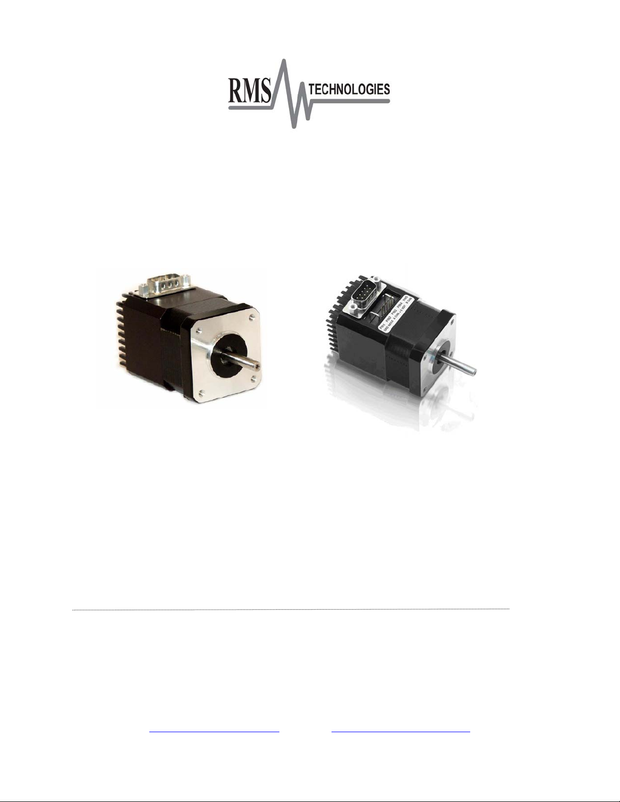
IMD17/IMDE17
INTEGRATED STEP MOTOR AND DRIVER
With Encoder Option
USER MANUAL
Version 1.04
RMS Technologies
2533 N. Carson St. #4698, Carson City, NV 89706-0147
1-877-301-3609
Page 2

Thank you for purchasing the IMD17 or the IMDE17 - Integrated Motor and R208 Driver.
This product is warranted to be free of manufacturing defects for one year from the date of
purchase.
Technical Support for RMS Technologies
By Telephone: 877-301-3609
(Mon.-Fri., 8:00 a.m.-5:00 p.m.)
On the Web: www.rmsmotion.com
Via Email: [email protected]
PLEASE READ BEFORE USING
Before you start, ensure that there is a suitable DC power supply. A current limited lab
supply is recommended for first time users to guard against the possibility of miswiring. In
addition, a suitable STEP and DIRECTION pulse source is also required.
DISCLAIMER
The information provided in this document is believed to be reliable. However, no
responsibility is assumed for any possible inaccuracies or omissions. Specifications are
subject to change without notice.
RMS Technologies reserves the right to make changes without further notice to any
products herein to improve reliability, function, or design. RMS Technologies does not
assume any liability arising out of the application or use of any product or circuit described
herein; neither does it convey any license under its patent rights, nor the rights of others.
CHANGES TO THE DRIVER BOARD
The IMD17/IMDE17 is an integrated Step Motor and R208 driver.
Prior to OCTOBER 1, 2005 the R208 driver board used slower opto-couplers, limiting the
step pulse timing. The old driver board also read step pulses on the rising edge. A revision
change was made on October 1, 2005, using more advanced opto-couplers. These new
opto-couplers can read faster data, yet they are also more sensitive to older PLC step
pulses. If your step pulse signal is not clear, the R208 will pick this up and the motor will
rotate “rough” and irratic. The new boards read step pulses on the falling edge. If the
falling edge of your step pulse is not a clear signal, the motor will rotate “rough” and irratic.
So far, only a small handful of customers have been affected by the change. Mostly those
that use PLC’s from the early 90’s and older. Customers can still request the old R208
boards in quantities of 100 per order (blanket releases are OK). The old boards are under
part number: R208-05.
Special Symbols
Indicates a WARNING
loss of property, or even death (in extreme cases).
and that this information could prevent injury,
RMS Technologies Page 2 Version 1.04
IMD17/IMDE17 10/1/2007
Page 3

IMD17/IMDE17 User Manual
Product: IMD17/IMDE17
Version: 1.04
Date: 10/1/2007
Version Date Description of Changes
1.00
1.01 04/10/2006 Edited Encoder information
1.02 02/02/2007 Standardization of user manuals
1.03 6/7/2007 Added min. order qty for R208-05;
1.04 10/1/2007 Updated internal resistor info and
Version History
updated description of opto supply.
recommended resistors for opto-
isolated inputs.
RMS Technologies Page 3 Version 1.04
IMD17/IMDE17 10/1/2007
Page 4

TABLE OF CONTENTS
1. FEATURES 5
IMDE17 - ENCODER FEATURES 5
DEFAULT SETTINGS 5
2. ELECTRICAL SPECIFICATIONS 6
POWER SUPPLY REQUIREMENTS 6
DRIVER 6
MOTOR SPECIFICATIONS 6
LOGIC INPUT TIMING 7
4. MECHANICAL SPECIFICATIONS 7
DIMENSIONS 8
5. CONNECTORS 9
6. GETTING STARTED 10
ALTERNATIVE STEP RESOLUTION CONNECTION 11
7. CONFIGURING AND CONTROLLING THE IMD17 11
SIGNAL CONTROL SPECIFICATIONS 11
INTERNAL SCHEMATIC 12
RESISTOR VALUES FOR THE OPTO SUPPLY 12
8. TROUBLESHOOTING 13
RMS Technologies Page 4 Version 1.04
IMD17/IMDE17 10/1/2007
Page 5

FEATURES
• NEMA Size 17, 2 Phase, 1.8° Bipolar Step Motor w/ Built-In Microstepping Driver
• Operates from +12 to 24 VDC
• Step Resolution: Full, 1/2, 1/4, 1/8
• Optically Isolated Step, Direction, and Disable/Enable Inputs
• Automatic Current Reduction with Disable Switch
• Low Power Dissipation
• Efficient Current Control
• Quiet Operation
• Thermal Shutdown, Under-Voltage Protection
• Power-On Indicator
• Power Disable/Enable Control
• Sinusoidal current waveform
• Phase Current Range from 0.35 to 2.0 Amp
• Default Setting is 1.0 Amp RMS or, 1.4 Amp Peak
IMDE17 - Encoder Features
• 32 to 1250 cycles per revolution (CPR) chosen by customer
• 2 Channel Quadrature
• TTL Squarewave Outputs and optional index (3rd Channel)
• E2 US Digital Encoder
Pin Number Function
1 Ground
2 Index*
3 Channel A
4 + 5 VDC
5 Channel B
Table 1: Encoder Pinouts
*Optional Index Channel
Default Settings
Default Settings
Step Resolution 8x Microstep
Direction of rotation Counterclockwise
Holding Current 23% of motor’s
rated Current
RMS Technologies Page 5 Version 1.04
IMD17/IMDE17 10/1/2007
Table 2
The IMD17 is set to these default settings
when Pins 2, 3, 4, and 5 are left open.
Page 6

2. ELECTRICAL SPECIFICATIONS
Power Supply Requirements
Voltage +12 VDC to +24 VDC
Driver
Peak Current: 0.35 to 2.0 Amps OR 0.25 to 1.4 Amps
Motor Specifications
NEMA Size 17
Holding Torque (default – 23% holding current):
IMD17-S05 34.5 oz-in
IMD17-M04 48.5 oz-in
IMD17-L04 63.9 oz-in
Holding Torque (special* – 100% holding current):
IMD17-S05 45 oz-in
IMD17-M04 63 oz-in
IMD17-L04 83 oz-in
Steps per Revolution (1.8° Motor)
200, 400, 800, 1600
*NOTE: The IMD17/IMDE17 by default use 23% of the run current as it’s hold current. If
your require more holding torque, the other option is to use 100% of the run current as
your holding current, which must be special ordered.
RMS Technologies Page 6 Version 1.04
IMD17/IMDE17 10/1/2007
Page 7
3. OPERATING SPECIFICATIONS
Operating Temperature: -20° to 50° Celsius
Humidity Range: 0 to 95% (non-condensing)
100% duty cycle is OK as long as bottom of unit is 50°C or less (bottom of unit is
where the black heat sink fins are located)
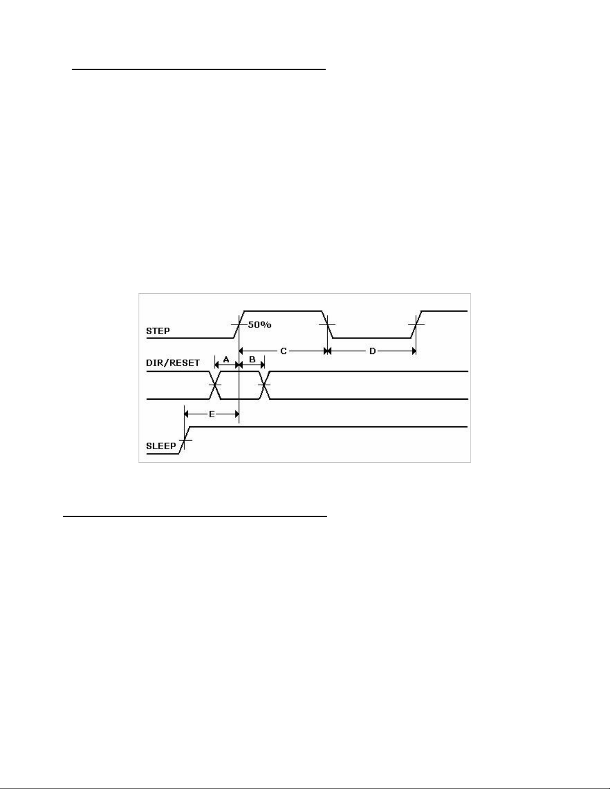
Logic Input Timing
(A) Minimum Command Active Time
Before Step Pulse (Data Set-up Time) 200 nanoseconds
(B) Minimum Command Active Time
After Step Pulse (Data Hold Time) 200 nanoseconds
(C) Minimum Step Pulse Width 20 microseconds
(D) Minimum Step Low Time 20 microseconds
(E) Maximum Power-Down Recovery Time 20 milliseconds
Maximum Step Frequency 25 kHz
Figure 1: Timing Diagram
4. MECHANICAL SPECIFICATIONS
A. Motor Front Shaft Extension Length
Standard length is 0.94”. Customized length is available.
B.
Motor Shaft Diameter
Standard shaft diameter is 0.1968”. Customized diameter length is also
available.
Overall Body Length
C.
Motor body length is available in various lengths
IMD17-S05 (2.69”)
IMD17-M04 (2.92”)
IMD17-L04 (3.24”)
RMS Technologies Page 7 Version 1.04
IMD17/IMDE17 10/1/2007
Page 8
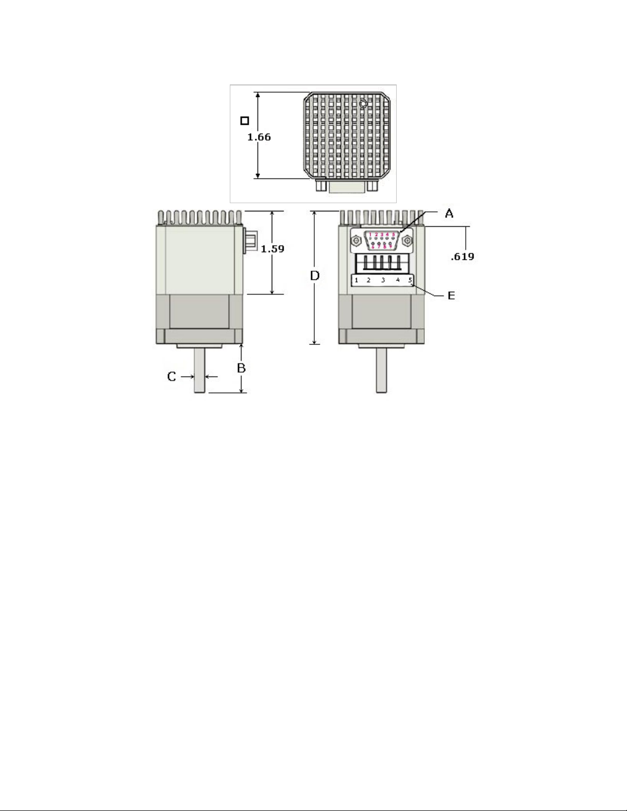
Dimensions
Figure 2: Dimensions Diagram
RMS Technologies Page 8 Version 1.04
IMD17/IMDE17 10/1/2007
Page 9

5. CONNECTORS
A DB-9 female connector cable receives power and provides the control connections for the
IMD17 Unit. Active signals are optically isolated. An open-collector drive is required to provide
pulses for Step, levels for Direction and Disable/Enable.
PIN # COLOR
(#26 AWG Lead)
1 Red +V Motor Supply Voltage. +12 to +24 VDC
2 Black SR1 Input Step Resolution 1. Pins 2 & 3 are used to
3 Brown SR2 Input Step Resolution 2. Pins 2 & 3 are used to
4 Black/White Enable/Disable
5 Orange Direction Input This input is used to change the rotation
6 Green Power Ground The ground or return of power supply
7 White Logic Ground Used to ground to the logic functions (i.e.
8 Blue Opto Supply +5 VDC input used to supply power to the
9 Yellow Step Clock Connects to the open-collector drive.
WARNING! - Do not apply differential voltage on SR1 and SR2, this will damage
the driver.
FUNCTION DESCRIPTION
preset the step resolution by selective
contact to ground (Pin 7)
preset the step resolution by selective
contact to ground (Pin 7)
This input is used to enable/disable the
Input
Table 3: Pin Assignments
output of the driver
direction of the motor
connects here.
step resolution)
isolated logic inputs**
The Resistors shall be connected in series with each Input: Pin 4 (Disable), Pin 5 (Direction), and
**
Pin 9 (Step) if you are to use an opto supply of more than +5VDC. See Section 7.
Figure 3: DB-9 Female Cable Connector (Rear View)
RMS Technologies Page 9 Version 1.04
IMD17/IMDE17 10/1/2007
Page 10

6. GETTING STARTED
In order to properly connect your new IMD17 Unit, first take a look at Figure 4, below.
Here’s a list of the parts needed to make the motor run:
• +12 to 24 Volt Power Supply
• Additional +5 Volt Power Supply
• Function Generator
1. Ensure that the IMD17 is not connected to the Main Power Supply until the
following procedures have been properly carried out.
2. Connect Pin 8 to the Positive Terminal of the +5 VDC Power Supply.
3. Connect the Negative Terminal of the +5 VDC Power Supply to the Negative
Terminal of the Signal Generator. This will be referred to as the Signal
Ground.
4. Connect Pin 1 and Pin 6 to the Positive and Negative Terminals of the Main
Power Supply, respectively.
5. Adjust the Frequency of the Signal Generator to achieve the desired
operating speed.
Figure 4: Connections Diagram
WARNING! DO NOT DISCONNECT THE DB-9 CABLE FROM THE IMD17 UNIT WHILE
POWER IS STILL BEING SUPPLIED. THIS MAY CAUSE DAMAGE TO THE INTERNAL
DRIVER BOARD.
WARNING! If you do not have a +5 VDC Power Source, use a Resistor in series to
limit the current of the opto isolators. See following page for Resistor values. If
the current exceeds 10 mA, the opto couplers cease to function.
RMS Technologies Page 10 Version 1.04
IMD17/IMDE17 10/1/2007
Page 11

ALTERNATIVE STEP RESOLUTION CONNECTION
It is possible to change the microstepping resolution by using the signal from the
controller.
Figure 5: Alternative Step Resolution Connection
By sending a high signal to Pin 2 and/or Pin 3, the connection between these pins
will be effectively closed with Pin 7. This will change the microstepping resolution.
Please refer to the Table 3 for Step Resolution Settings.
PLEASE NOTE: The microstepping resolution should not be changed on the fly, loss of step
may occur.
7. CONFIGURING AND CONTROLLING THE IMD17
SIGNAL CONTROL SPECIFICATIONS
Step Resolution SR1
(Black)
SR2
(Brown)
Full Close Close
Half Close Open
1/4 Open Close
1/8 Open Open
WARNING! Do not change the Step Resolution on the fly, loss of step will occur.
Enable/Disable
Enable Open
Disable Close
Table
Disable the Driver by closing the connection
between Pin 4 and Signal Ground.
Direction
Clockwise Close
Counterclockwise Open
Table 6: Direction Settings
Change direction of rotation by closing the
connections between Pin 5 and the Signal
Ground.
RMS Technologies Page 11 Version 1.04
IMD17/IMDE17 10/1/2007
Table 4: Step Resolution Settings
SR1 (Pin 2) and SR2 (Pin 3) are used
to preset the step resolution by
selective contact closure to ground (Pin
7).
5: Enable/Disable Settings
Page 12
INTERNAL SCHEMATIC
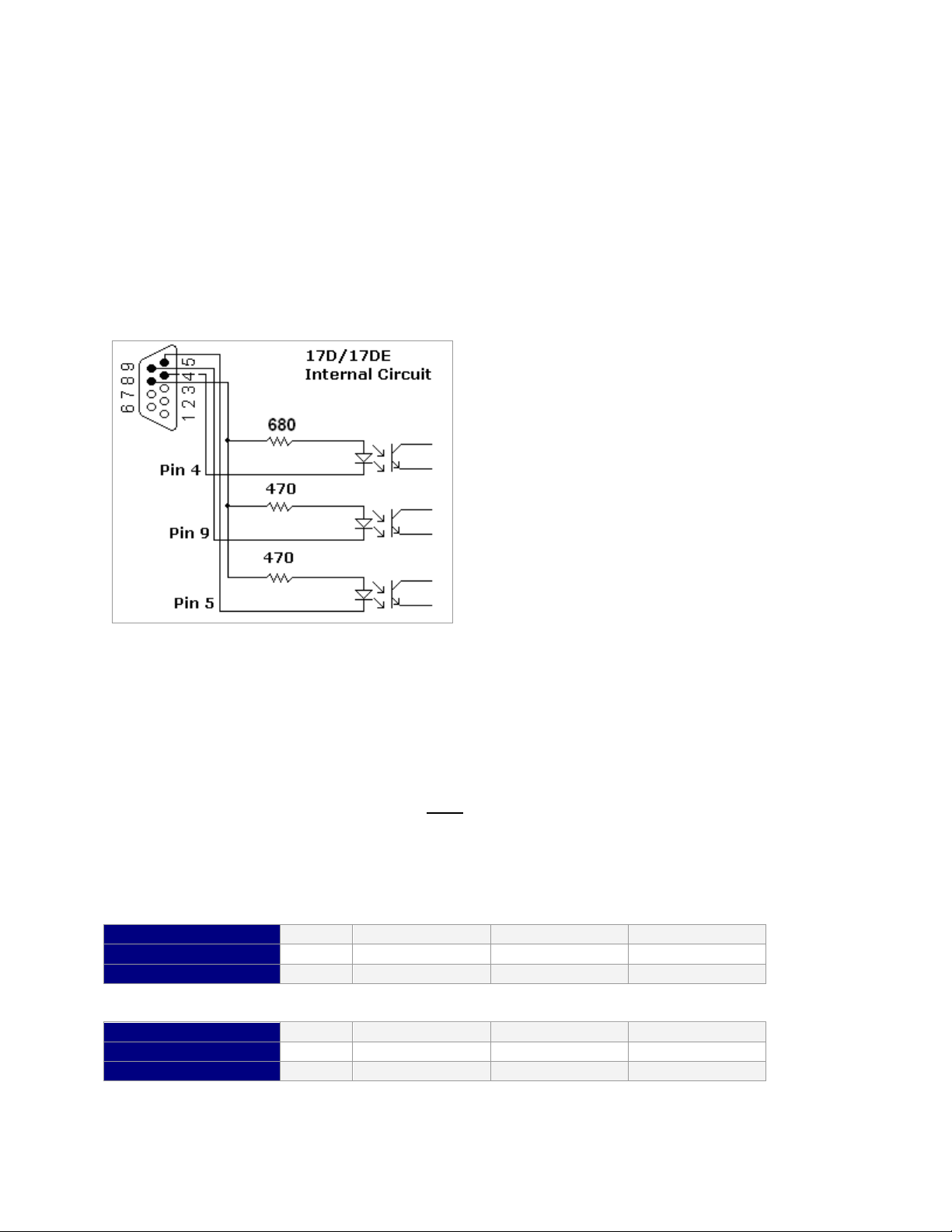
The IMD17 has 3 optically isolated logic inputs. These inputs are isolated to minimize or
eliminate electrical noise coupled onto the drive control signals. Each input is internally
pulled-up to the level of the optocoupler supply and may be connected to sinking outputs on
a controller or a PLC. These inputs are:
Enable/Disable (Pin 4)
Direction (Pin 5)
Step Clock (Pin 9)
Figure 6: Optically Isolated Inputs
Within the Driver lies three 680 Ω
Resistors and three Optocouplers.
The current is limited to 7 mA due to
these three Opto Couplers.
Resistor Values for the Opto Supply
The optocouplers must be powered by an external power supply to maintain isolation. The
Opto Supply for the optocouplers can be between +5 to 24 VDC with respect to the signal
input. It is recommended to use a +5 VDC Opto Supply in order to limit the current going
into the optocouplers to 10 mA. However, if the supply is greater than +5 VDC then a
resistor must be connected in series with each signal line to maintain 10 mA of current
running through the optocouplers. Do NOT
occur to the driver. Refer to Table 7 & 8 for the corresponding Resistor Values.
The Resistors shall be connected in series with each Input: Pin 4 (Disable), Pin 5 (Direction), and Pin 9
(Step).
Step & Direction lines have a 470 ohm internal resistor
Voltage: 5V 10V 15V 24V
Ohms needed: 0 500 1000 2000
Wattage rating: 0 ¼ watt ¼ watt ½ watt
Disable line has a 680 ohm internal resistor
Voltage: 5V 10V 15V 24V
Ohms needed: 0 750 1500 2700
Wattage rating: 0 1/8 watt ¼ watt ½ watt
Table 7 & 8: Resistor Values for inputs
RMS Technologies Page 12 Version 1.04
IMD17/IMDE17 10/1/2007
provide more than 10 mA or damage may
Page 13

8. TROUBLESHOOTING
The Motor is in Holding Position, but does not rotate.
This means that Power is being supplied to the driver and motor, so the power supply is
OK. However, the signal generator might be causing the problem. Try changing the
signal to TTL. If this doesn't help, is the external +5 VDC Power connected? Is Pin 4
(disable) touching Pin 7 (logic ground)? This will disable the driver from running.
The Microstepping does not always change to the correct step resolution.
Changing the microstepping "on the fly" might ruin the driver. It is recommended to
disable the motor from running (either turn power off, or use the disable pin), then
change the step resolution.
RMS Technologies Page 13 Version 1.04
IMD17/IMDE17 10/1/2007
 Loading...