

Page 1
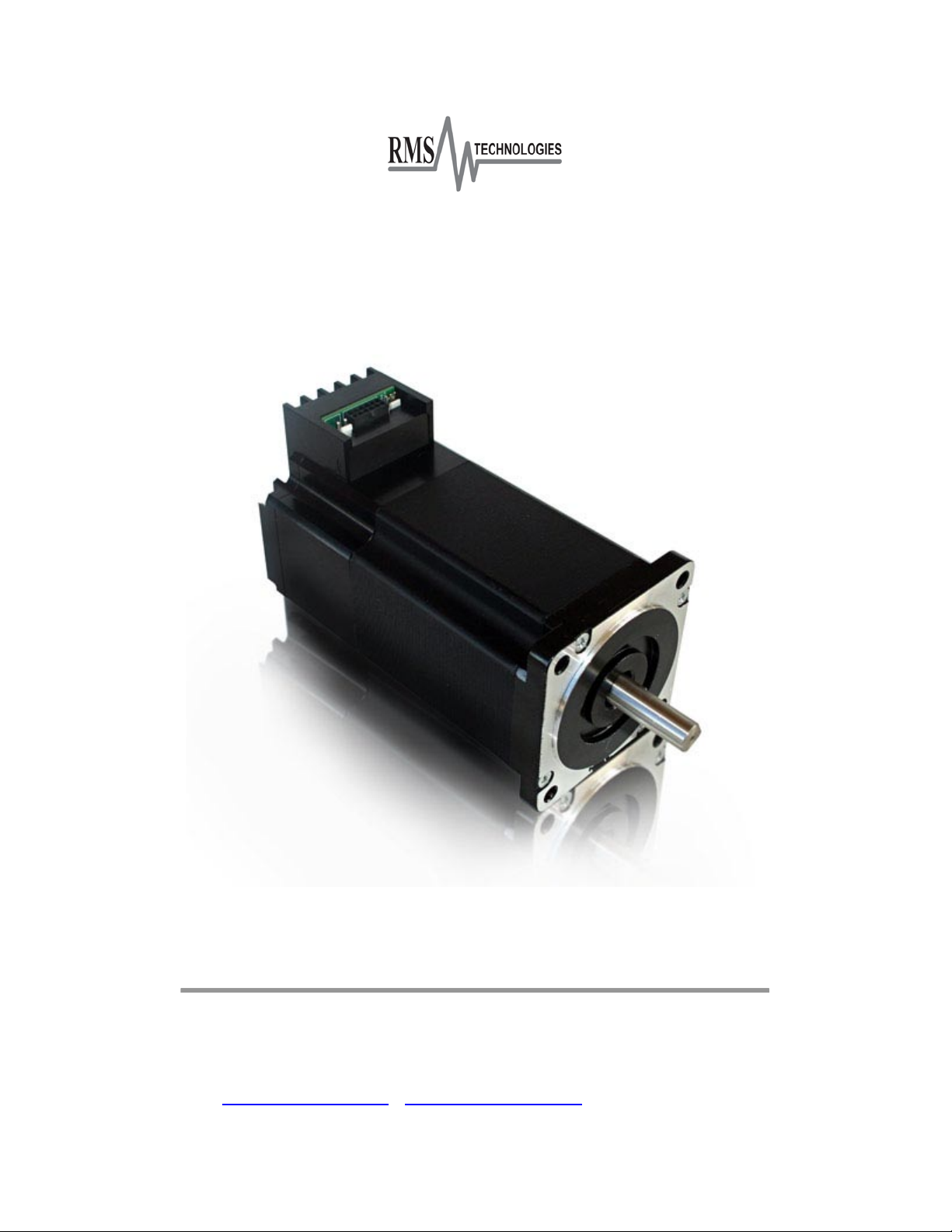
IMD34 / IMDE34
Integrated NEMA 34 Motor and Drive
With Encoder option
User Manual
And Commands Guide
Version 1.00
RMS Technologies
2533 N. Carson St. #4698, Carson City, NV 89706-0147
www.rmsmotion.com . [email protected] . 1-877-301-3609
Page 2

RMS Technologies Page 2 Version 1.00
IMD34 / IMDE34 User Manual 4/28/2009
Thank you for purchasing the IMD34 or IMDE34 Integrated Motor and Driver. This product
is warranted to be free of manufacturing defects for one (1) year from the date of purchase.
PLEASE READ BEFORE USING
Before you start, you must have a DC power supply suitable for the motor. It is
recommended to use a power supply voltage between 4 times and 20 times the motor's
rated voltage. (Rated voltage can be calculated by multiplying the motor’s rated current
and the motor’s resistance value).
DISCLAIMER
The information provided in this document is believed to be reliable. However, no
responsibility is assumed for any possible inaccuracies or omissions. Specifications are
subject to change without notice.
RMS Technologies reserves the right to make changes without further notice to any
products herein to improve reliability, function, or design. RMS Technologies does not
assume any liability arising out of the application or use of any product or circuit described
herein; neither does it convey any license under its patent rights, nor the rights of others.
Page 3
RMS Technologies Page 3 Version 1.00
IMD34 / IMDE34 User Manual 4/28/2009
IMD34/IMDE34 User Manual
Product: IMD34 and IMDE34
Version: 1.00
Date: 4/28/2009
Version History
Version
Date
Description of Changes
1.00
4/28/2009
New Manual
Page 4

RMS Technologies Page 4 Version 1.00
IMD34 / IMDE34 User Manual 4/28/2009
Table of Contents
1 FEATURES ......................................................................................................................................................... 5
POLE DAMPING TECHNOL OGY™ ................................................................................... 5
IMDE34 – ENCODER FEATURES .................................................................................. 5
DEF A UL T SETTINGS .................................................................................................. 5
2 ELECTRICAL SPECIFICATIONS ............................................................................................................. 6
3 OPERATING SPECIFICATIONS ............................................................................................................. 6
4 MECHANICAL SPECIFICATIONS .......................................................................................................... 7
5 MOTOR MOUNTING SPECIFICATIONS ............................................................................................. 9
6 PIN ASSIGNMENTS ................................................................................................................................... 10
CONTROL PIN OU TS & DESCRIPTION (P2) ................................................................... 11
MAIN POWER PINOUTS & DESCRIPTION (P1) ............................................................. 11
COMMUNICATION VIA RS485 PINOUTS & DESCRIPTIO N (P3) ........................................ 11
7 CONFIGURING THE SETTINGS ........................................................................................................... 12
CONNECTING THE IMD34 TO YOUR PC VIA USB .......................................................... 12
CONNECTING THE IMD34 TO YOUR PC VIA RS232 ....................................................... 14
USING HYPERTE R MI N AL TO SET MOTOR PARAMETERS ................................................... 15
USING THE GUI SOFTWARE TO SET PARAMETERS: ........................................................ 18
8 CONNECTION SPECIFICATIONS ........................................................................................................ 19
USING EXTERNAL 5VDC SUPPLY FOR OPTOS ................................................................. 21
USING INT ER NA L 5VDC SUPPLY FOR OPTOS ................................................................ 21
USING MORE THAN 5VDC FOR EXTERNAL S UPPLY FOR THE O PTOS ..................................... 22
RESISTOR VALUES FOR THE OPTO SUPPLY ................................................................... 22
9 STEP SENSING ............................................................................................................................................. 24
10 GUI ERROR CODES .................................................................................................................................... 26
Page 5
RMS Technologies Page 5 Version 1.00
IMD34 / IMDE34 User Manual 4/28/2009
1 FEATURES
• NEMA Size 34, 2 Phase, 1.8° Bipolar Step Motor w/ Built-In Microstepping Driver
• Operates from +24 to 75 VDC
• Selectable phase currents from 0.5 to 7.0 Amp Peak (in 0.1 A increments)
• Selectable hold currents from 0.0 to 7.0 Amps (in 0.1 A increments)
• Hold current delay time from 0.5 seconds to 6.0 seconds
• Step Resolutions include: Full step, 2x, 4x, 8x, 16x, 32x, 64x, 128x, and 256x
microstepping
• Three Selectable Damping modes (Fast decay, mixed decay of 25% and 75%)
• Step sensing on the rising or falling edge of step pulse input
• Direction of rotation enables user to start rotation CW or CCW
• Three optically isolated control inputs (step, direction, disable)
• Sinusoidal current waveform to provide smooth motion
• Pole Damping Technology™ integrated within driver board
Pole Damping Technology™
Pole Damping Technology™ (PDT) enhances step motor performance by dampening each
full step in order to create a more accurate and smooth motion profile. Microstepping the
step motor will optimize Pole Damping Technology™. PDT outputs the correct amount of
run and hold currents to the motor, at the right time. Thus, it will overcome the step
motor’s natural tendency to want to forcefully pull towards the full step ON position.
IMDE34 – Encoder Features
• 32-2500 cycles per revolution (CPR)
• 128 to 10000 pulses per revolution (PPR)
• 2 Channel Quadrature
• TTL Squarewave Outputs and optional index (3rd Channel)
• Compatible with E2, E5, E5D, or E3 US Digital Encoder
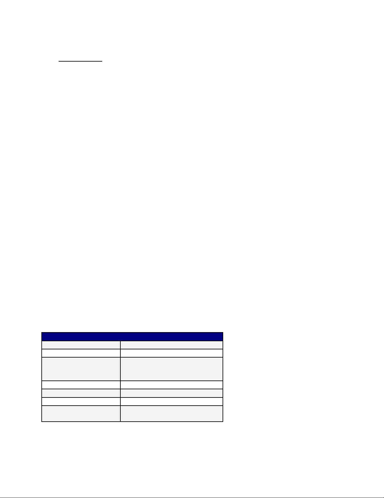
Default Settings
Default Settings of the IMD34 and IMDE34
Direction of rotation
Counterclockwise
Step Resolution
8x step (3200 steps/rev)
Run Current
Motor’s rated current or up to
7 Amps Peak if motor is rated
for 7 or higher.
Holding Current
2.5 Amps
Damping Mode
75% mixed decay
Step signal sensing
Senses on the rising edge
Delay time from run
to hold current
0.7 Seconds
Table 1: Default settings
Page 6

RMS Technologies Page 6 Version 1.00
IMD34 / IMDE34 User Manual 4/28/2009
2 ELECTRICAL SPECIFICATIONS
Power Supply Requirements
Voltage +24 VDC to 75 VDC
Driver
Peak Current: 0.5 to 7.0 Amps Peak
Motor Specifications
NEMA Size 34
Holding Torque when using motor’s rated current:
IMD34-S 435 oz-in
IMD34-M 830 oz-in
IMD34-L 1288 oz-in
Steps per Revolution (1.8° Motor)
200, 400, 800, 1600, 3200, 6400, 12800, 25600
I/O Specifications
3x Optically Isolated Inputs: step, direction, disable
3 OPERATING SPECIFICATIONS
Maximum Step Frequency:
5 MHz
Operating Temperature*:
-20°C to 75°C measured at the heat sink
-20°C to 90°C measured at the motor case
Duty cycle:
100% as long as temperatures do not
exceed 75°C on the heat sink and 90°C on
the motor case.
* RMS Technologies integrated motor and drive products are designed and fully tested to withstand the rated
operating temperature ranges.
Logic Timing
Minimum Step Pulse Width 100 nanoseconds
Minimum Step Low Time 100 nanoseconds
Maximum Power-Down Recovery Time 20 milliseconds
Page 7

RMS Technologies Page 7 Version 1.00
IMD34 / IMDE34 User Manual 4/28/2009
4 MECHANICAL SPECIFICATIONS
Motor Front Shaft Extension Length
Standard length is 1.46 +/- 0.02”.
Motor Shaft Diameter
Standard shaft diameter is 0.5000” +0.0000/-0.0005, with two flats, 90° apart.
Overall Body Length (A)
Motor body length is available in various lengths
IMD34-S (4.44”)
IMD34-M (5.62”)
IMD34-L (6.80”)
Dimensions
Figure 1: Front Mounting dimensions
Page 8

RMS Technologies Page 8 Version 1.00
IMD34 / IMDE34 User Manual 4/28/2009
Figure 2: Side view of IMD34
Fig 3: Side connection view Fig 4: Bottom view
Fig 5: E3 encoder drawing
Page 9
RMS Technologies Page 9 Version 1.00
IMD34 / IMDE34 User Manual 4/28/2009
5 MOTOR MOUNTING SPECIFICATIONS
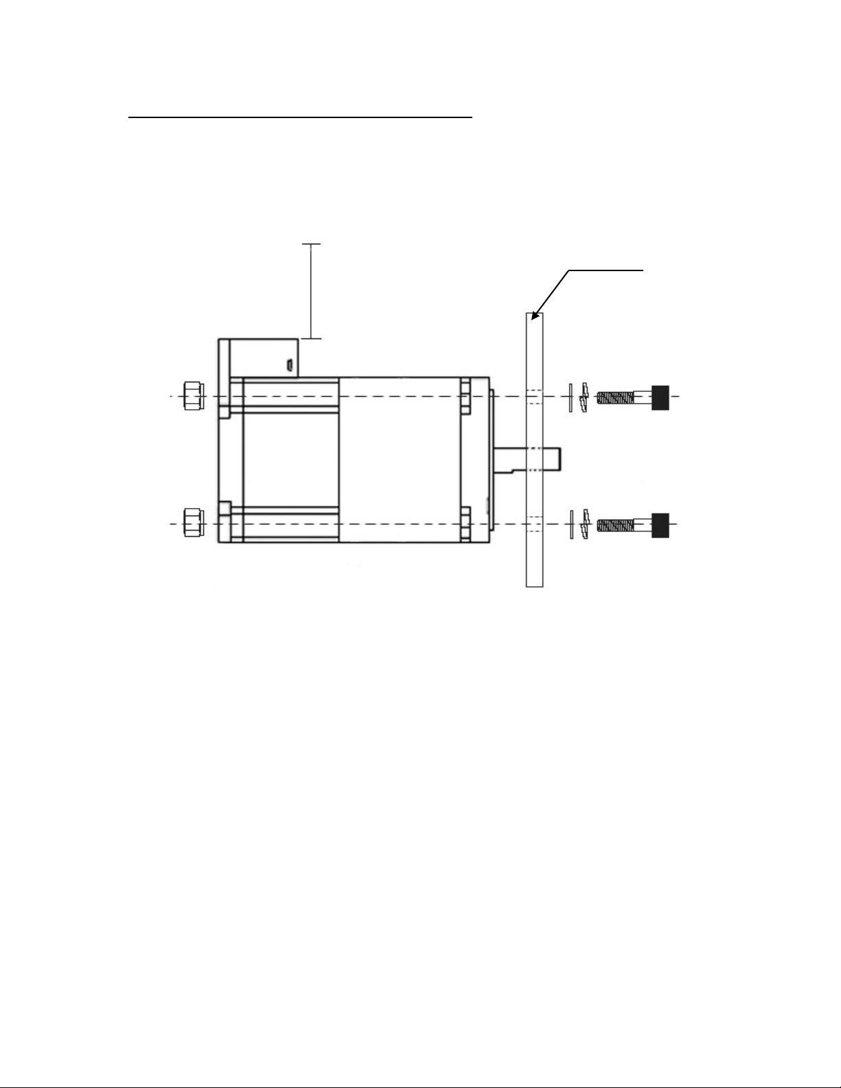
There are four (4) 0.258” thru holes on the motor flange for mounting the motor to an
adapter plate. Recommended screws for mounting the motor are 0.250” or ¼-20.
Figure 6: Mounting Specifications
Recommended hardware (not included with IMD34)
4 x ¼-20 screw
4 x ¼” Split lockwasher
4 x ¼” Flat washer
4 x ¼-20 lock nuts
Adapter Plate / Mounting
Allow 1.0” to 1.5”
clearance for cables
Page 10

RMS Technologies Page 10 Version 1.00
IMD34 / IMDE34 User Manual 4/28/2009
6 PIN ASSIGNMENTS
A female 12-Pin connector cable provides the control connections for the IMD34 unit. Active
signals are optically isolated. An open collector drive is required to provide pulses for Step,
levels for Direction, and Disable/Enable.
A separate 2-Pin connector needs to receive main power between +24VDC to 75VDC.
All of the signals are optically isolated. The common opto supply can be +5 to 30 VDC with
respect to the signal input; however if the supply is greater than 5 VDC then a resistor must
be inserted in series with each signal line to limit the current to 10 mA.
Figure 7: Image of IMD34
Figure 8: Close-up view of pinouts
Figure 9: Pin numbers for all three connections
3-Pin RS485
communication
12-Pin control
functions
2-Pin Main
Power
Heat sink
P1
P2
P3
Page 11
RMS Technologies Page 11 Version 1.00
IMD34 / IMDE34 User Manual 4/28/2009
Control Pinouts & Description (P2)
Provides input to the IMD34 driver.
Color
Pin
Function
Description
Black
1
No Connection
This pin is not used
Blue
2
Opto supply input
This pin requires 5VDC to supply the optically isolated
inputs (use resistors if supply is greater than 5V) See
end of Section 6 for details.
White
3
Disable/Enable input
This input is used to enable/disable the driver/motor.
By default, the unit is enabled. Tie to ground in order
to disable unit. When disabled, no power is sent.
Red
4
Internal 5V supply
(output)
The IMD34 has an internal 5V supply. To use this as
your opto supply, jump pins 2 and 4 together. By
doing so, the inputs are no longer optically isolated;
the main power and this 5V supply share the same
circuit.
Green
5
Ground
Same as main ground.
Black
6
Internal use
Internal use
Black
7
No Connection
This pin is not used
Yellow
8
Step Pulse Input
This pin takes in step pulses from a controller, PLC, or
signal generator. The step pulse must be a clean TTL
squarewave signal, max of 10 mAmps current. If
needed, use resistors to limit it to 10mAmps.
Brown
9
Direction Input
This input is used to change the direction of rotation.
By default, it rotates counterclockwise (CCW). By tying
this pin to ground, the motor should rotate CW.
Black
10
No Connection
This pin is not used
Black
11
No Connection
This pin is not used
Black
12
No Connection
This pin is not used
Table 2: Pin Assignments for Controls
Note: All Black wires above are for “No-Connection”
Main Power Pinouts & Description (P1)
Provides main power to the IMD34
Color
Pin
Function
Description
Red
1
PWR +ve
Motor Supply Voltage. +24 to 75 VDC
Black
2
PWR –ve (GND)
The ground or return of the power supply connects
here
Table 3: Pin Assignments for Power
Communication via RS485 Pinouts & Description (P3) Provides connection to the PC via RS485 in order to set motor parameters.
Color
Pin
Function
Description
Red
1
RS485A (-ve)
RS485 communication (A-)
Black
2
Ground (GND)
Ground connection (must connect to power supply
ground
Green
3
RS485B (+ve)
RS485 communication (B+)
Table 4: Pin Assignments for Communication
In order to set the run current, hold current, step resolution, damping or decay modes, step
and direction of rotation, you must connect to a PC and program these settings. View
section 7 which describes how to configure the settings via the GUI software.
Page 12

RMS Technologies Page 12 Version 1.00
IMD34 / IMDE34 User Manual 4/28/2009
7 Configuring The Settings
Connecting IMD34 to your PC via USB
All units come with the following cables:
- A 12-Pin cable for supplying step, direction, and other functions
- A 2-Pin cable for main power
If you purchased a USB485 Designer’s Kit (RMS p/n USBKIT-03), then you should have
received the following items:
- A 3-Pin to 3-Pin cable
for communication
(p/n 090-00202)
- USB to RS485
converter card
- A USB cable (6 feet
long)
If you purchased a RS232-485 Designer’s Kit (RMS p/n RS232KIT-03), then you should
have received the following items:
- An extra 3-pin cable
- An RS232 to 485
converter card
- A 3-Pin to 3-Pin cable
for communication
(p/n 090-00202)
Page 13
RMS Technologies Page 13 Version 1.00
IMD34 / IMDE34 User Manual 4/28/2009
1. Download driver files for the USB485 converter card
Go to www.rmsmotion.com and navigate to the USB485 converter card page by going
to: Accessories USB to RS485 Converter card. Then click on “Download”, or simply
scroll to the bottom of the page.
Save the zip file called “USB485 Driver Files” and extract all files to your PC.
2. Connect the USB485 converter card to the IMD unit.
If using RMS Technologies’ USB485 converter card, simply take the 3-Pin to 3-Pin cable
and plug one end to the converter card, and plug the other end to the IMD34.
3. Connect USB cable to the PC.
Then plug one end of the USB cable into the converter card and the other end into your
PC.
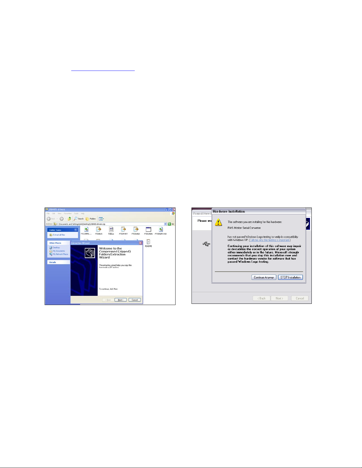
When the converter card connects to your PC, it will find the new hardware and
automatically ask you to download files. It will download two files.
Figure 10: Extracting files
Figure 11: Downloading driver files
Page 14
RMS Technologies Page 14 Version 1.00
IMD34 / IMDE34 User Manual 4/28/2009
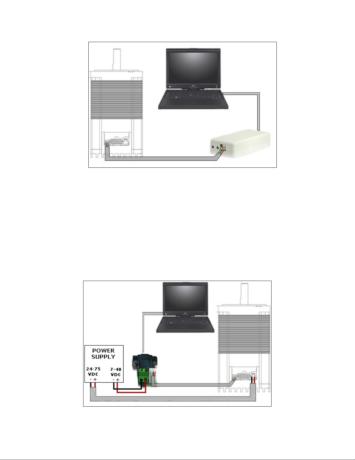
Fig 12: Connection of IMD motor to USB Card to PC
Note the COM Port number that was assigned to the converter card device by rightclicking on “My Computer” and going to:
Hardware Tab Device Manager Ports (COM & LPT) RMS Motion US485
Connecting the IMD34 to your PC via RS232
If you purchased a Designer’s Kit, then you should have received the following items:
- RS485-to-RS232 converter card (Black gray cover, DB-9 on one end)
- 3-Pin to IDC connector type of cable with flying lead wires (36 inches long)
Follow the connection schematic shown below if using the RS485-RS232 Converter card.
Fig 13: Connection of IMD motor to RS485-232 Card & PC
Page 15
RMS Technologies Page 15 Version 1.00
IMD34 / IMDE34 User Manual 4/28/2009
Connecting Power
After downloading files for the USB485 converter card, connect main power to the
IMD34.
Using HyperTerminal To Set Motor Parameters
Open a HyperTerminal connection by going to:
All Programs Accessories Communications HyperTerminal
1. Settings
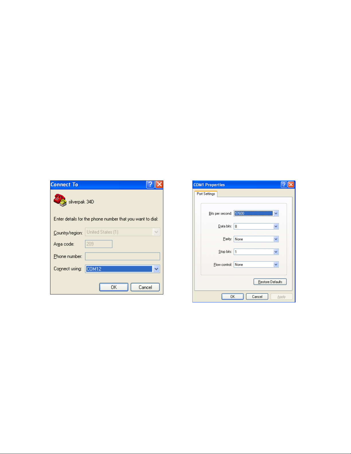
Give your connection a name. It will then ask you to select the correct COM port. See
note above this section to find the COM Port number.
It should direct you to the properties of the connection. Or, click on “Configuration” in
the Properties section. Click on the default settings, or:
57600 Bits per second, 8 data bits, none parity, 1 stop bits, none flow control:
Figure 14: Selecting the COM port
Figure 15: Port settings
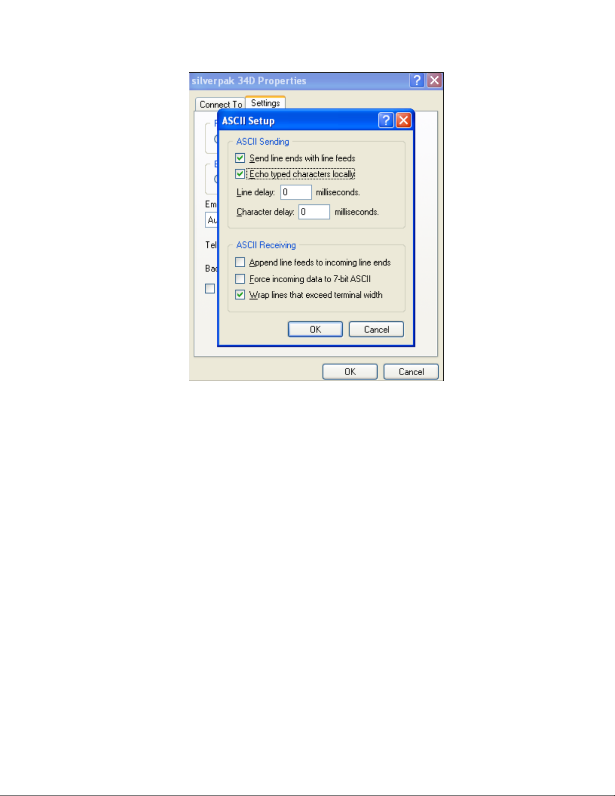
Next, go to File Properties Settings tab ASCII setup and check box the top two
options:
Send line ends with line feeds
Echo typed characters locally
Page 16
RMS Technologies Page 16 Version 1.00
IMD34 / IMDE34 User Manual 4/28/2009
Figure 16: ASCII settings
Page 17

RMS Technologies Page 17 Version 1.00
IMD34 / IMDE34 User Manual 4/28/2009
2. Programming
If programming in HyperTerminal, follow the syntax shown below:
#[ADDRESS][COMMAND][VALUE]
The following list contains the parameters with examples for HyperTerminal:
Command
Range
Example
Default
value
Function
DR
0 or 1
#ADR1
0
Direction of Rotation. Changes direction of
rotation. By default, motor will rotate CCW.
FR
n/a
#AFR
n/a
Firmware Revision. Displays the existing
firmware revision.
HI
0 - 7000
#AHI5000
2500
Holding Current. Changes the amount of
current supplied to the motor while holding in
place (during which no step pulses are input
to the drive). Units are in mAmps, therefore
the default value sets the hold current to 2.5
Amps Peak.
HT
500 –
6000
#AHT500
2000
Hold Timeout. Sets the length of time unit
will go from running current to hold current (in
milliseconds).
LD
n/a
#ALD
n/a
Load Defaults. Loads default settings.
MA
A – Z
#AMAB
A
My Address. Changes the address of the
unit. Default is address “A”. All examples are
assuming the address is “A”.
PF
0 – 3
#APF2
1
Percent Fast Decay. Changes the decay
mode at which the current depletes after each
step is issued. 0 – Fast Decay; 1 – 25% fast
decay; 2 – 75% fast decay. General rule is to
use 0 for slow speeds, 1 and 2 for medium
and fast speeds, respectively.
RI
0 – 7000
#ARI5000
2500
Run Current. Changes amount of peak
current supplied to motor during running
(when step pulses are input to the drive).
Units are in mAmps, therefore the default
value sets the current to 2.5 Amps Peak.
SD*
n/a
#ASD
n/a
Save Data. After all settings have been set,
the user must type this command in order to
save all existing data set on the unit. If
settings are changed and power is lost,
changes will not be saved.
*NOTE: After entering desired parameters, you must enter #ASD, Save Data, to store values.
SR
1 – 256
#ASR4
8
Step Resolution. Sets the microstep
resolution of motor 1= full step, 2 = 2x, 4 =
4x, 8x, 16x, 32x, 64x, 128x, 256x.
SS
0, 1
#ASS1
1
Step Sensing. Senses each step pulse on the
falling or rising edge of the pulse. 0 for falling
edge, 1 for rising edge. Default is 1 for rising
edge.
Table 5: Programming commands
Page 18
RMS Technologies Page 18 Version 1.00
IMD34 / IMDE34 User Manual 4/28/2009
Example:
#AFR show the firmware version
#ASR256 set the step resolution to 256 microstepping
#ARI5000 set the current to 5A peak
#ASD Save data
Using the GUI Software to Set Parameters:
If using the GUI interface, simply download the executable from the IMD34 webpage in the
download section. Unzip the file.
Figure 17: GUI
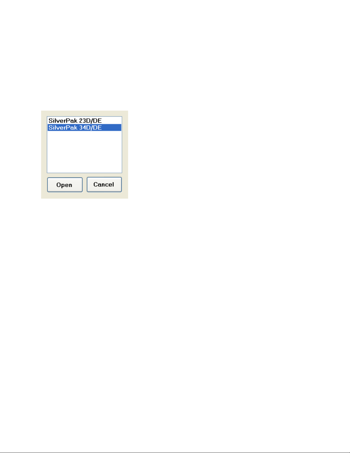
Upon opening the Driver GUI, a screen shown above will
pop up. Select the “IMD34/IMDE34” Product, and click
“Open”.
• Address = command “MA”
• Micro-step = command “SR”
• Run Current = command “RI”
• Hold Current = command “HI”
• Percent Decay = command “PF”
• Step – rising sensing / falling sensing =
command “SS”
• Forward direction / Reverse direction = command
DR
Page 19

RMS Technologies Page 19 Version 1.00
IMD34 / IMDE34 User Manual 4/28/2009
Figure 18: GUI Interface
8 Connection Specifications
List of components needed to rotate the motor:
• +24 to 75 VDC Power Supply
• Additional +5 VDC Volt Power Supply
• Signal Generator
Ensure that the IMD34 is not connected to the Main Power Supply until the following
procedures have been properly carried out.
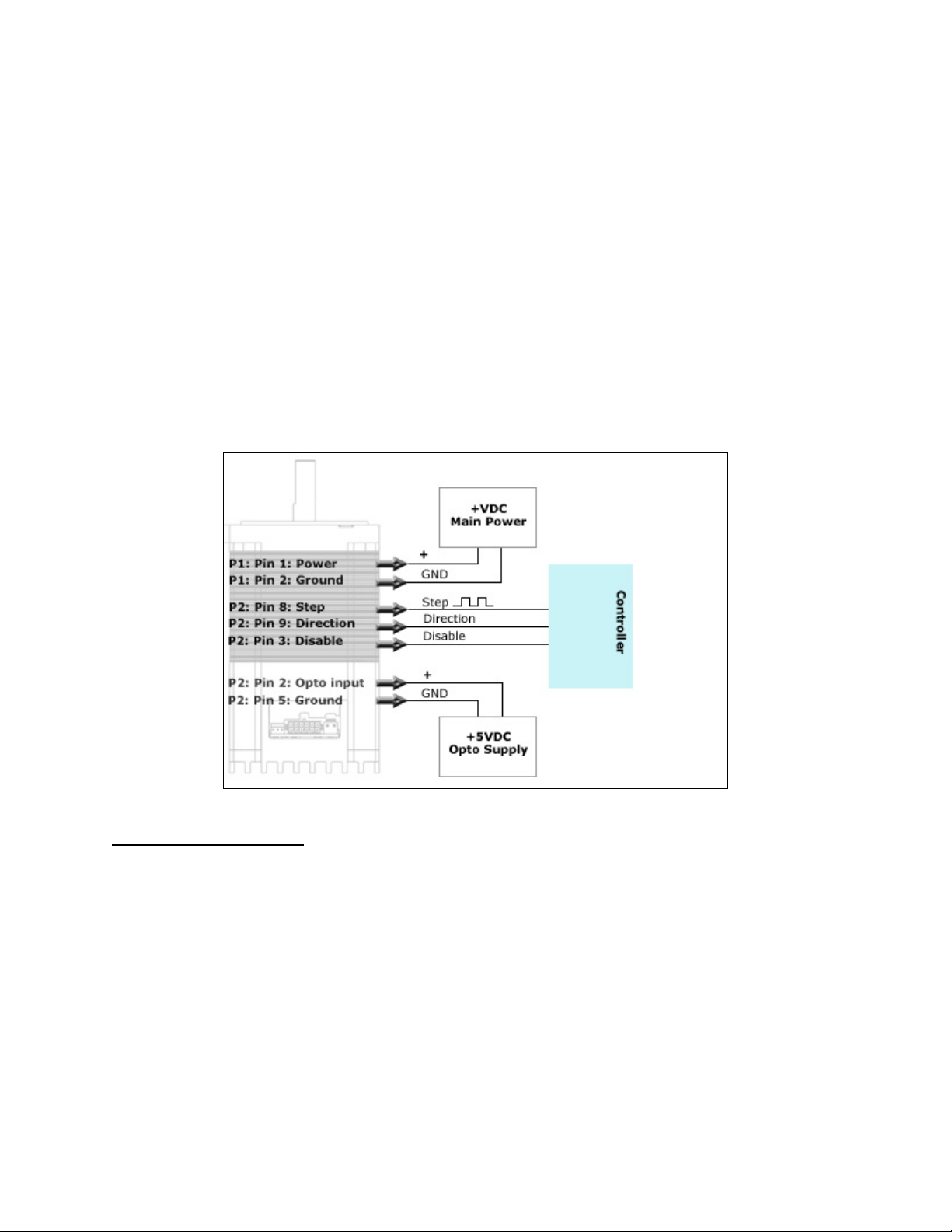
1. Connect the step pulse generator
Connect Pin 8, step pulse input, to the Positive Terminal of your pulse generator. Then
connect the negative terminal to main ground power.
2. Connect the 5VDC supply
The IMD34 requires a separate 5VDC supply for the optics that turn on the step,
direction, and disable inputs.
1. Set newly changed
settings. 2. Click “Save
DATA” to store values
to EEPROM
2
Reads back stored data
Loads default values
1
Click “Set All”
then “Save
DA TA ” to store
parameters
Reads IMD34 board
firmware version # and
date.
Page 20
RMS Technologies Page 20 Version 1.00
IMD34 / IMDE34 User Manual 4/28/2009
Connect the positive terminal of your 5VDC supply to Pin 2, the opto input supply. The
ground terminal of your supply should connect to the ground wire of the step pulse
function generator.
Users have an option to use the IMD34 internal 5VDC supply for ease of use. Connect
pin 2 to pin 4 with a wire. By doing so, the system is no longer optically isolated.
3. Connect the direction pin
The IMD34 unit will rotate counterclockwise if the direction pin is not connected to
anything. If the direction pin is pulsed low, the direction of rotation will change to a
clockwise direction.
Connect a switch from the direction pin to the ground connection on your opto supply.
4. Connect the disable pin
Simply connect a switch from the disable/enable pin to the ground connection on your
opto supply. Connection to ground will disable the drive. No power will go to the motor.
Figure 19: Connection Schematic – Connecting to a Controller
Connecting the Power
The IMD34 requires a supply voltage of +24-75 VDC. First, connect the positive end of the
power supply to Power (Pin 1), and then connect the negative of the power supply to the
Ground (Pin 2) on the IMD34.
WARNING! Be careful not to reverse the polarity from the power supply to the driver.
Reversing the connection will destroy your driver and void the warranty.
Page 21
RMS Technologies Page 21 Version 1.00
IMD34 / IMDE34 User Manual 4/28/2009
Connection Schematics
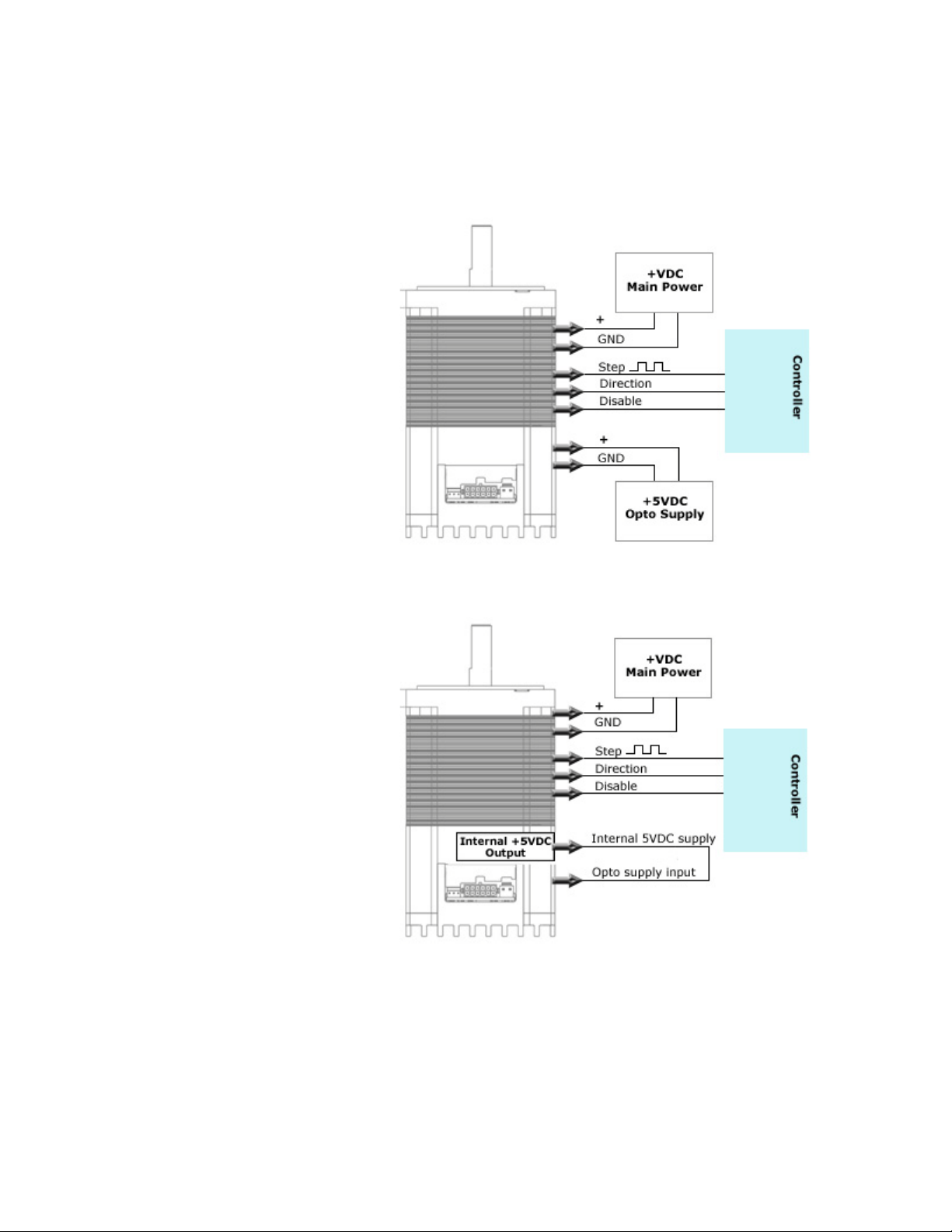
Using external 5VDC supply for optos
If using an external 5VDC supply,
connect the positive (+) terminal
to the IMD’s opto supply input,
PIN 2.
If using a signal generator,
connect the 5VDC supply ground
terminal to the negative line of
the generator.
Figure 20: Schematic with 5VDC
Using IMD’s Internal 5VDC supply for optos
If using the internal 5VDC supply,
simply connect PIN 2 to PIN 4.
Be sure to connect step pulse
ground to the IMD’s Ground, PIN
9.
Changing direction and disabling
the drive is achieved by
connecting these two inputs to
PIN 9, ground.
This type of connection no longer
optically isolates the inputs.
Figure 21: Schematic with internal 5VDC
Page 22

RMS Technologies Page 22 Version 1.00
IMD34 / IMDE34 User Manual 4/28/2009
Using more than 5VDC for external supply for the optos
If using more than 5VDC, connect
resistors in series with the opto
supply input, PIN 2. Use the table
below to determine what resistor
to use.
Connect the 5VDC supply ground
terminal to the IMD’s Ground, PIN
9.
Figure 22: Schematic for more than 5VDC
Resistor Values for the Opto Supply
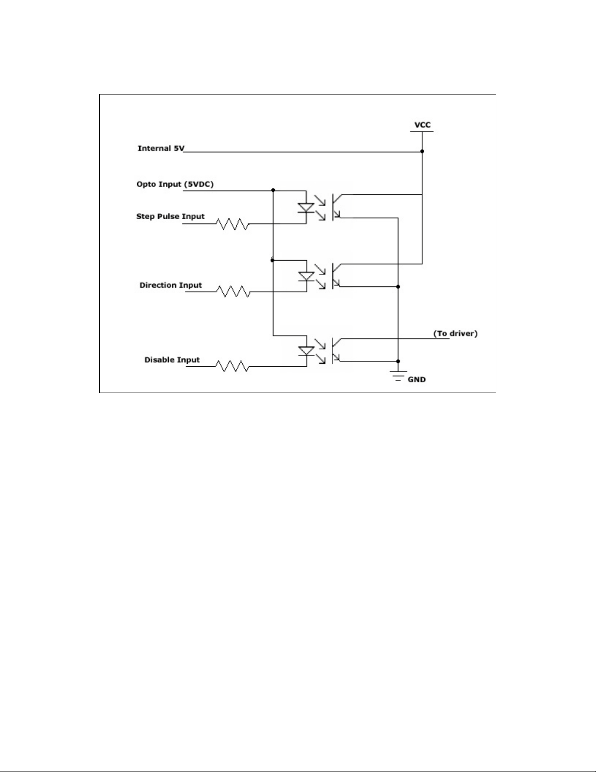
The optocouplers must be powered by an external power supply to maintain isolation. The
Opto Supply for the optocouplers can be between +5 to 24 VDC with respect to the signal
input. It is recommended to use a +5 VDC Opto Supply in order to limit the current going
into the optocouplers to 10 mA. However, if the supply is greater than +5 VDC then a
resistor must be connected in series with each signal line to maintain 10 mA of current
running through the optocouplers (step, direction, and disable lines). Do NOT provide
more than 10 mA or damage may occur to the driver.
Step, Direction, and Disable lines have a 475 ohm internal resistor
Voltage:
5V
10V
12V
15V
24V
Ohms needed:
0
500
668
1000
2000
Wattage rating:
0
¼ watt
¼ watt
¼ watt
½ watt
Table 6: Required resistance for more than 5VDC on opto supply input
If the desired voltage level is not listed above, below is how to calculate the resistor and
wattage:
Amps
R
Voltage
010.0
475=+Ω
or
Ω−
= 475
010.0 Amps
Voltage
R
AmpsVoltagePower ×=
or
AmpsVoltageWattage 010.0×=
Page 23
RMS Technologies Page 23 Version 1.00
IMD34 / IMDE34 User Manual 4/28/2009
Equation 1: Resistance Equations
Equation 2: Wattage equations
Figure 23: Internal Schematic for Inputs
475 Ω
475 Ω
475 Ω
(Step down to 5VDC)
Page 24
RMS Technologies Page 24 Version 1.00
IMD34 / IMDE34 User Manual 4/28/2009
9 Step Sensing
The IMD34 is equipped with a parameter setting that allows users to change how it reads
the step pulse input.
Step Sensing
This feature allows for more compatibility with controllers and PLC’s. The IMD34 driver
board receives step pulses from a pulse train, normally a TTL signal, sensing each pulse,
one by one.
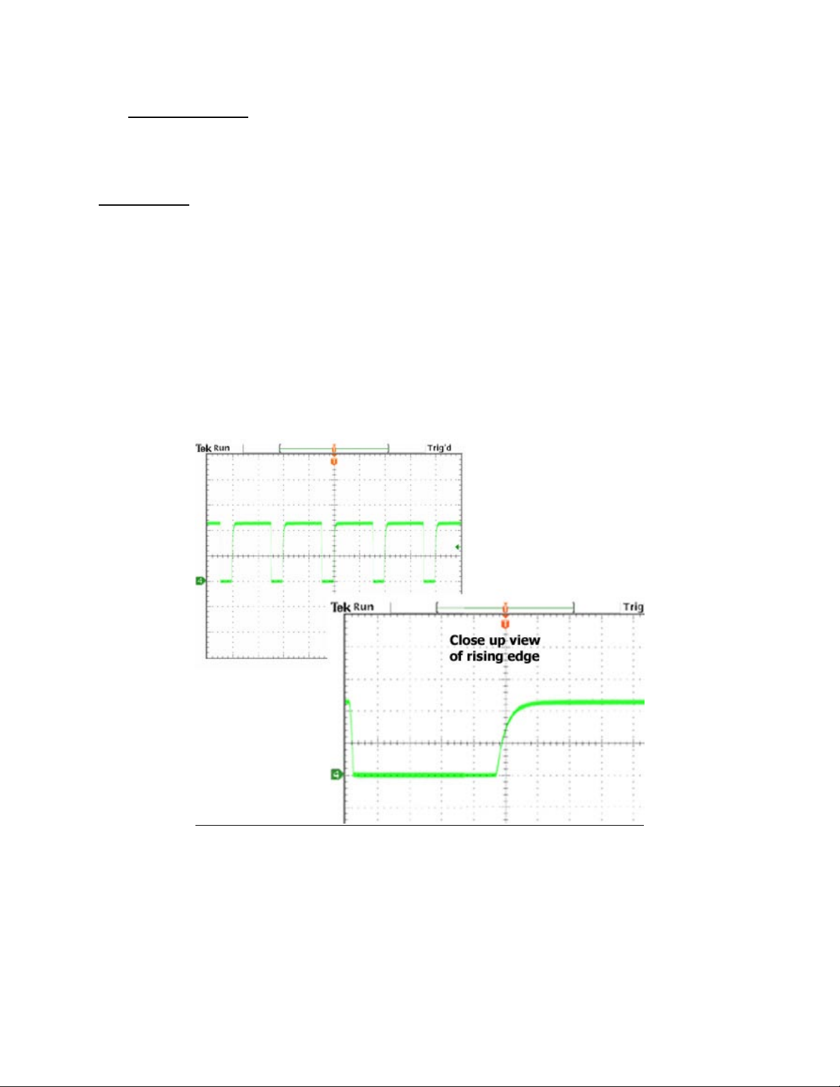
The “step sense” feature can choose where to sense each pulse: on the rising edge of the
step or the falling edge (also known as the positive or negative edge).
Below depicts a step pulse train waveform where the rising edge is more of a curve. If the
IMD34 is set to read this type of signal on the rising edge, inaccurate steps and unsmooth
motion may occur.
It is best to switch the step sensing to the negative edge, or falling edge. Notice in this
example, the falling edge is a clear signal and a definite difference between high to low.
Figure 24: Example of a bad rising edge waveform
Page 25
RMS Technologies Page 25 Version 1.00
IMD34 / IMDE34 User Manual 4/28/2009
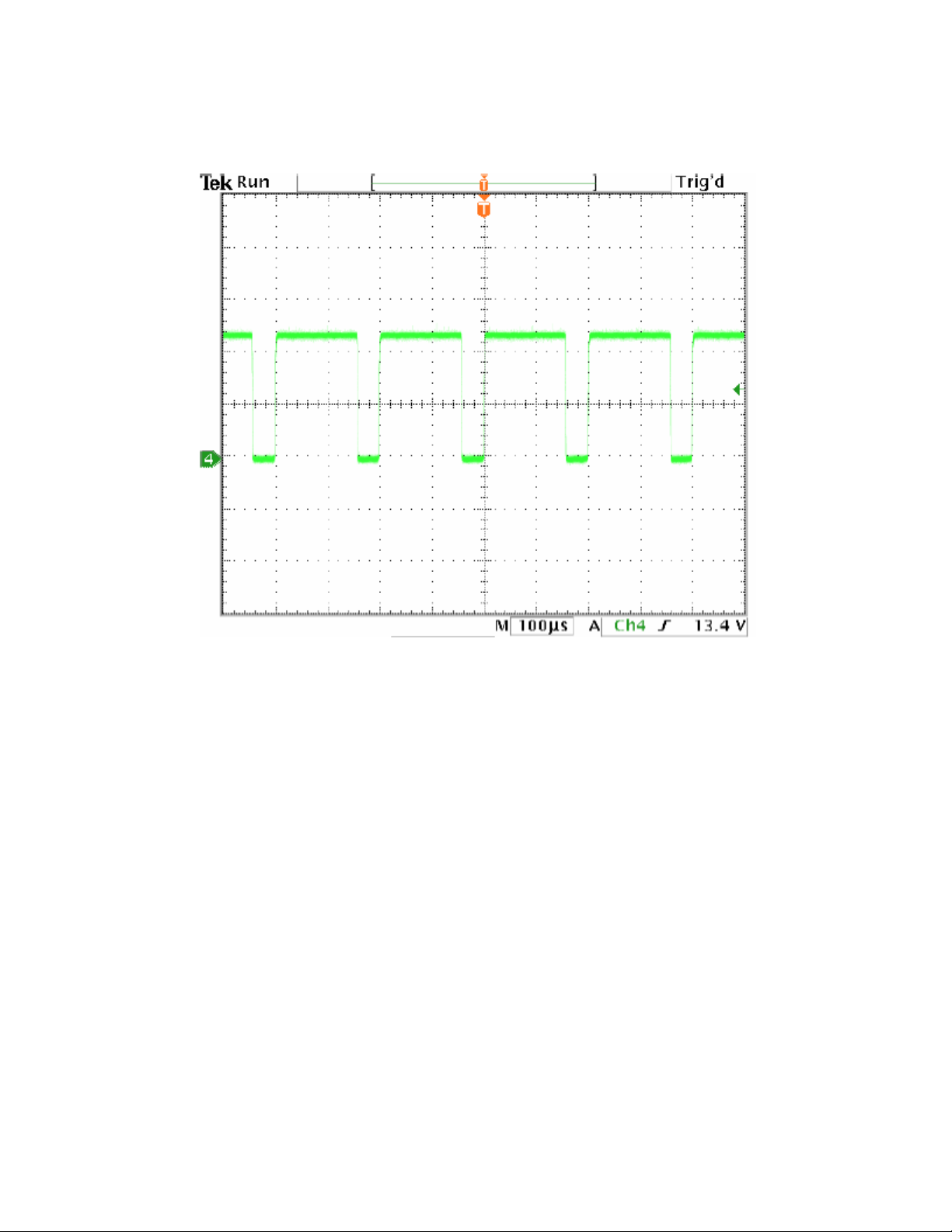
Below is an example of a good step pulse waveform where sensing the step on either edge
would be fine:
Figure 25: Example of a good waveform
Page 26

RMS Technologies Page 26 Version 1.00
IMD34 / IMDE34 User Manual 4/28/2009
10 GUI Error Codes
This error occurs if you click on “Save DATA”
and the board EEPROM does not respond.
Check for main power
Check for communication connection
Check COM Port number
This error occurs when you click on
“Connect” and the COM Port does not
respond.
Check for main power
Check for communication connection
Check COM Port number
This error occurs when you click on “Set” or
“Set All” and the driver board is not
receiving data from the PC.
Check for main power
Check for communication connection
Check COM Port number
This error occurs when you click on “Read
Data” and the device could not read any
parameters.
Check for main power
Check for communication connection
Check COM Port number
 Loading...