


English 16.9.2008
SERVICE MANUAL FOR HOIST CONTROL DEVICE

R&M Materials Handling, Inc.
4501 Gateway Boulevard
Springfield, Ohio 45502
P.: (937) 328-5100
FAX: (937) 325-5319
Read the instructions supplied with the product before installation and commissioning.
Keep the instructions in a safe place for future reference.
Table of content
1 General.......................................................... |
5 |
|
1.1 |
Description................................................. |
5 |
1.2 |
Directives, Standards and Patents ............. |
5 |
1.2.1 |
Directives ...................................................... |
5 |
1.2.2 |
Standards...................................................... |
5 |
1.2.3 |
Patent Pending.............................................. |
6 |
1.2.4 |
Certificate of compliance................................ |
6 |
2 Technical characteristics............................. |
7 |
|
2.1 |
Description of terminals ............................. |
8 |
2.2 |
Product description sticker ....................... |
10 |
3 Display unit ................................................. |
11 |
|
3.1 |
Push-buttons............................................ |
11 |
3.2 |
LEDs........................................................ |
11 |
3.3 |
Display information .................................. |
12 |
3.3.1 Tare load / actual load mode........................ |
12 |
|
3.3.2 |
Menu Mode ................................................. |
13 |
3.3.3 |
Status mode ................................................ |
13 |
3.3.4 Sum load / solo hoist load mode .................. |
13 |
|
3.4 |
Menus...................................................... |
14 |
3.4.1 |
Moving in menus ......................................... |
14 |
3.4.2 |
Password .................................................... |
14 |
3.4.3 |
Hoist selection (only multi-hoists)................. |
14 |
3.5 |
Parameters .............................................. |
15 |
3.5.1 |
Read-only parameters ................................. |
15 |
3.5.2 |
Adjustable parameters................................. |
15 |
3.6 |
Remote Display ....................................... |
16 |
3.6.1 |
General ....................................................... |
16 |
4 Parameters.................................................. |
18 |
|
4.1 |
Passwords ............................................... |
20 |
5 Basic Functions.......................................... |
21 |
|
5.1 |
General.................................................... |
21 |
5.2 |
Overload protection.................................. |
22 |
5.3 |
Hoist motor overheating supervision ........ |
23 |
5.3.1Hoist motor overheating supervision
instructions .............................................................. |
25 |
|
5.4 |
Supply voltage phase supervision............ |
26 |
5.4.1 Supply phase supervision instructions ......... |
26 |
|
5.5 |
RUN and fault supervision ....................... |
27 |
5.6Starting and stopping through slow speed (2
speed application only) ..................................... |
28 |
5.6.1Starting and stopping through slow speed
instructions .............................................................. |
28 |
5.7 Sudden load increase supervision............ |
29 |
5.7.1Sudden load increase supervision instructions 29
6 Monitoring Items......................................... |
30 |
|
6.1 |
General.................................................... |
30 |
6.2 |
Primary monitoring items ......................... |
30 |
6.2.1 |
Starts counter .............................................. |
31 |
6.2.2 |
Run Time counter ........................................ |
31 |
6.2.3 |
Safe Working Period counter (SWP%)h....... |
31 |
6.2.4 |
Hoist cycles counter .................................... |
32 |
6.2.5 |
Run time and start counter for trolley and |
|
bridge |
32 |
|
6.3 |
Measured values...................................... |
33 |
7 Optional functions ...................................... |
34 |
|
7.1 |
General.................................................... |
34 |
7.2 |
Slack rope protection ............................... |
34 |
7.2.1 |
Slack rope protection instructions ................ |
34 |
7.2.2 |
Slack rope protection connections ............... |
35 |
7.3 |
Intermediate load limits ............................ |
35 |
7.3.1 |
Intermediate load limits parameters ............. |
35 |
7.3.2 |
Intermediate load limits connections ............ |
36 |
7.4Run time and start counter for trolley and
bridge................................................................ |
36 |
7.4.1Run time and start counter for trolley and
bridge parameters.................................................... |
37 |
7.4.2Run time and start counter for trolley and
bridge connections................................................... |
37 |
|
7.5 |
Analogue output....................................... |
37 |
7.5.1 |
Analogue output parameters........................ |
37 |
7.5.2 |
Analogue output connections....................... |
38 |
7.6 |
Free relay output...................................... |
38 |
7.7 |
Hoist brake-wear supervision ................... |
39 |
7.7.1 |
Hoist brake-wear supervision instructions .... |
39 |
7.8 |
Load tare.................................................. |
40 |
7.8.1 |
Load tare instructions .................................. |
40 |
7.9 |
Levelling function ..................................... |
40 |
7.9.1 |
Levelling function instructions ...................... |
40 |
7.9.2 |
Levelling Function Connections ................... |
41 |
8 Multi-hoisting .............................................. |
42 |
|
8.1 |
General.................................................... |
42 |
2/104
R&M Materials Handling, Inc. reserves the right to alter or amend the above information without notice.

|
R&M Materials Handling, Inc. |
|
|
4501 Gateway Boulevard |
|
|
Springfield, Ohio 45502 |
|
|
P.: (937) 328-5100 |
|
|
FAX: (937) 325-5319 |
|
8.2 |
Multi-hoisting instructions......................... |
42 |
8.2.1 |
Multi-hoisting parameters............................. |
42 |
8.2.2 |
Cabling........................................................ |
43 |
8.2.3 Menus through CAN bus.............................. |
44 |
|
8.3 |
CAN-bus topology.................................... |
45 |
8.3.1 |
Termination resistors ................................... |
45 |
8.3.2 |
Recommended topologies ........................... |
46 |
9 Commissioning .......................................... |
47 |
|
9.1 |
Start-up.................................................... |
47 |
9.2 |
Load measure.......................................... |
47 |
9.2.1Load measure type by ”Motor”, (see the
parameter 4-7-1)...................................................... |
47 |
9.2.2Load measure type by ”Sens.”, (see the
parameter 4-7-1)...................................................... |
47 |
|
9.3 |
Functional checks .................................... |
48 |
9.3.1 |
Multi hoisting ............................................... |
48 |
9.3.2 |
Multifunction inputs...................................... |
48 |
9.3.3 Functional free relay output ROUT............... |
49 |
|
9.3.4 |
Analog output AOUT.................................... |
50 |
9.3.5 |
Slack rope ................................................... |
50 |
9.4 |
Commissioning table................................ |
51 |
10 Overload protection – Load sensor .......... |
52 |
|
10.1 |
Load sensor-system................................. |
52 |
10.1.1 |
Load sensor set-up...................................... |
52 |
10.2 |
Load sensor parameters .......................... |
52 |
10.3 |
Load calibration sequence with load sensor |
|
|
53 |
|
10.4 |
Manual load calibration ............................ |
54 |
11 Overload protection – Motor torque.......... |
55 |
|
11.1 |
Overload protection instructions............... |
55 |
11.1.1 |
Motor torque calculation-system .................. |
55 |
11.1.2 Motor torque calculation parameters ............ |
55 |
|
11.2 |
Connections............................................. |
57 |
11.3Load calibration sequence with motor torque 58
11.4Zero load calibration sequence with motor toque59
11.5 |
Manual load calibration ............................ |
59 |
12 Load sensor adjustment ............................ |
61 |
|
12.1 |
KAE400 + Strain Gauge.......................... |
61 |
12.1.1 |
General ....................................................... |
61 |
12.1.2 |
Technical data............................................. |
61 |
12.1.3 |
Wiring.......................................................... |
61 |
12.1.4 |
Adjustment .................................................. |
62 |
12.1.5 |
Dimensions ................................................. |
63 |
12.2 ESD142 amplifier + Strain Gauge ............ |
63 |
|
12.2.1 |
ESD142 Description .................................... |
63 |
12.2.2 |
Adjustment .................................................. |
64 |
12.2.3 |
Zero load adjustment ................................... |
64 |
12.2.4 |
Adjustment with higher load......................... |
64 |
12.2.5 |
Connections ................................................ |
65 |
3/104 |
|
|
13 Faults and warnings ................................... |
66 |
|
13.1 |
Faults....................................................... |
66 |
13.1.1 Fault codes and description ......................... |
66 |
|
13.2 |
Warnings.................................................. |
67 |
13.2.1 |
General warnings ........................................ |
67 |
13.2.2 |
Service warnings ......................................... |
67 |
14 Troubleshooting ......................................... |
68 |
|
14.1 |
Fault descriptions..................................... |
68 |
14.1.1 |
Fault Hoist OL F_OL.................................. |
68 |
14.1.2 Fault Motor OT F_OT .................................. |
70 |
|
14.1.3 |
Fault Int. relay F_SR.................................... |
70 |
14.1.4 Fault RUN act. F_Run ................................. |
70 |
|
14.1.5 |
Fault Run FB – (2) ..................................... |
70 |
14.1.6 |
Fault Brake F_Br ......................................... |
71 |
14.1.7 |
Fault Br wear F_Brw................................... |
71 |
14.1.8 Fault Sensor ch. F_SCh .............................. |
72 |
|
14.1.9 |
Fault Curr.meas. F_Ain................................ |
72 |
14.1.10 Fault Supply vol F_SPh ............................... |
73 |
|
14.1.11 Fault Phaseorder F_Sor .............................. |
73 |
|
14.1.12 Fault CParameter F_CP .............................. |
73 |
|
14.1.13 Fault MParameter F_MP.............................. |
73 |
|
14.1.14 Fault CAN bus F_CAN................................. |
74 |
|
14.1.15 Fault Bridge OL F_BOL ............................... |
74 |
|
14.1.16 Fault Bridge RS F_Brs................................. |
74 |
|
14.1.17 Fault Slack Rope – (2) ................................ |
74 |
|
14.2 |
No Signal – (2) ........................................ |
74 |
14.3 |
Blank display............................................ |
75 |
14.4 |
The temperature sensors (NTC-wiring) .... |
75 |
14.5 |
Current transformers................................ |
75 |
14.6 |
There is no fault, but hoist doesn’t work ... |
76 |
14.6.1 Hoisting works, but lowering is prevented .... |
76 |
|
14.6.2 Hoisting and lowering prevented.................. |
77 |
|
15 Replacement Instructions .......................... |
78 |
|
15.1 |
General.................................................... |
78 |
15.2 |
Ordering a new Monitoring unit ................ |
78 |
15.3 |
Replacing................................................. |
78 |
15.4 |
Parameters and Values............................ |
78 |
15.5 |
Flow chart ................................................ |
81 |
16 Menu structure............................................ |
82 |
|
16.1 |
Monitor 1 (Menu 1)................................... |
82 |
16.2 |
Monitor 2 (Menu 2)................................... |
83 |
16.3 |
Load calibration menu (Menu 3)............... |
84 |
16.4 |
Start-up menu (Menu 4) ........................... |
85 |
16.5 |
Service menu (Menu 5)............................ |
88 |
16.6 |
Design values menu (Menu 6) ................. |
88 |
16.7 |
GO –settings menu (Menu 7) ................... |
89 |
Appendix 1 - Default parameters ................... |
90 |
|
Appendix 2 - Version History ......................... |
91 |
|
Appendix 3 - Current Transformer’s |
|
|
information ...................................................... |
93 |
|
Appendix 3.1 Current transformer table ........ |
95 |
|
R&M Materials Handling, Inc. reserves the right to alter or amend the above information without notice.

R&M Materials Handling, Inc.
4501 Gateway Boulevard
Springfield, Ohio 45502
P.: (937) 328-5100
FAX: (937) 325-5319
Appendix 4 |
- Motor temperature NTC charts 97 |
|
Appendix 5 |
- Example connections |
............... 98 |
Appendix 6 |
- External power supply for ESD |
|
143.................................................................. |
|
101 |
Appendix 7 - Replacing the condition |
|
monitoring unit.............................................. |
103 |
4/105
R&M Materials Handling, Inc. reserves the right to alter or amend the above information without notice.

R&M Materials Handling, Inc.
4501 Gateway Boulevard
Springfield, Ohio 45502
P.: (937) 328-5100
FAX: (937) 325-5319
1 General
1.1Description
The hoist-monitoring unit is an electronic device designed to supervise and protect the hoist. The hoistmonitoring unit measures the use of the hoists and prevents hoisting or lowering in case a situation is detected which can cause a potential dangerous situation. The hoist-monitoring unit records the use of the hoist and calculates the remaining Safe Working Period “SWP” according to the FEM and ISO standards.
The hoist-monitoring unit is designed to fit a wide variety of hoists and motor drives. It can be used with variable speed control drives, as well as two speed drives. The hoist-monitoring unit contains tailored hardware and software, especially designed for crane use.
With the display, the unit can be programmed and calibrated, and stored values can be read. The hoistmonitoring unit can be equipped and installed with many different options and additional features such as:
•continuous load display
•tandem operation (up to five units)
•service-warning information
•hook levelling
•intermediate overload options
A service agent authorised by the manufacturer can provide detailed information and professional advice on a tailored solution for each application.
The hoist-monitoring unit is a safety device, installed by the manufacturer. Only service personnel authorised by the manufacturer are allowed to program and calibrate the unit. Faulty programmed or calibrated unit may cause malfunctions that results in dangerous situations.
Under no circumstances it is allowed to by-pass or remove the hoist-monitoring unit, as that would disable all supervision and safety features.
1.2Directives, Standards and Patents
1.2.1 Directives
The product conforms to the relevant safety provisions of the
•EMC Directive (2004/108/EC)
•Low Voltage Directive (2006/95/EC)
1.2.2 Standards
The product complies with the following standards:
•EN 50081-1 (1992) Generic emission standard: Residential, commercial and light industry
•EN 61000-6-2 (1999) Generic immunity standard: Industrial environment
•EN 50178 (1997) Electronic equipment for use in power installations
•EN 60204-32 (1998) Safety of machinery – Electrical equipment of machines. Part 32: Requirements for hoisting machines
•EN 12077-2 (1998) Cranes safety. Requirements for health and safety. Part 2: Limiting and indicating
devices
5/105
R&M Materials Handling, Inc. reserves the right to alter or amend the above information without notice.

R&M Materials Handling, Inc.
4501 Gateway Boulevard
Springfield, Ohio 45502
P.: (937) 328-5100
FAX: (937) 325-5319
1.2.3 Patent Pending
•US09/940,514 EP01000406,7
•US09/940,464 EP01000405,9
1.2.4 Certificate of compliance
•1334676 (LR025623)
6/105
R&M Materials Handling, Inc. reserves the right to alter or amend the above information without notice.

R&M Materials Handling, Inc.
4501 Gateway Boulevard
Springfield, Ohio 45502
P.: (937) 328-5100
FAX: (937) 325-5319
2 Technical characteristics
120.3
1 |
|
|
|
0 |
|
|
|
|
8 |
|
|
|
|
. |
|
|
|
|
5 |
|
|
8 |
|
|
. |
|
3 |
|
2 |
|
|
1 |
|
|
Signal name |
Technical data |
Maximum supply voltage |
690 VAC +10% |
Nominal supply frequency |
50/60 Hz |
Control voltage range |
42…48 VAC +/- 10% or 115…230 VAC +/- 10% |
|
|
Maximum power consumption |
Imax = 4,5A peak value |
Power consumption |
6W …8W |
|
|
Ambient temperature |
-20ºC…+65ºC; 0ºF…+150ºF |
|
|
Storage temperature |
-40ºC…+85ºC; -40ºF…+185ºF |
Humidity |
0…100% RH, no condensation |
Analogue output |
0…10V, Rmin=1k |
10VDC output |
10…12 VDC, Imax=50mA |
|
|
Potential free relay output (Programmable) |
230VAC, 3A |
|
|
Current loop |
12 V, I = 50…70mA |
CAN |
0: Ucan-H = 2.5VDC, Ucan-L = 2.5VDC |
|
1: Ucan-H = 3.5VDC, Ucan-L = 1.5VDC |
|
(respect to CAN-GD) |
Height (including 15mm assembly rail) |
120.3mm; 4.73in |
Length |
123.8mm; 4.87in |
|
|
Width |
108.5mm; 4.27in |
Tightening torque of connector terminal screw |
0,4 Nm – 0,6 Nm |
7/105
R&M Materials Handling, Inc. reserves the right to alter or amend the above information without notice.
R&M Materials Handling, Inc.
4501 Gateway Boulevard
Springfield, Ohio 45502
P.: (937) 328-5100
FAX: (937) 325-5319
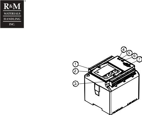
2.1Description of terminals
c_cid1a
1.Connector X1: Terminals 1-19 for “power signals” (high voltage)
2.Display unit with pushbuttons and three indication LEDs (optional)
3.Connector X2: Terminals 20 -38 for the measurement signals (low voltages).
4.Green LED (OK and run state indication)
5.Red LED (warning and fault indication)
6.Selection switch for display location (inside the unit or remote)
7.RS232 serial link, e.g. for PC software (optional) or PLC system
Connector X1:
Terminal |
Signal |
Description |
|
1 |
LOUT |
Provides the control voltage to lower down contactor (two step control) or lower down request. (inverter drive) |
|
2 |
HOUT |
Provides the control voltage to hoist up contactor (two step control) or hoist up request (inverter drive) |
|
3 |
FOUT |
Provides the control voltage to fast speed contactor (two step control) or fast stop control (stop limit or fault in |
|
inverter drive) |
|||
|
|
||
4 |
OL |
Control voltage, line |
|
5 |
ON |
Control voltage, neutral |
|
6 |
MFI2 |
Multifunction input 2 (programmable) |
|
7 |
MFI1 |
Multifunction input 1 (programmable) |
|
8 |
FIN |
Fast speed request or run feedback in inverter drive |
|
9 |
LIN |
Lowering request |
|
10 |
HIN |
Hoisting request |
|
11 |
ROUT |
Relay output (programmable) |
|
12 |
RIN |
|
|
13 |
- |
Not used |
|
14 |
- |
Not used |
|
15 |
L3 |
Input voltage measurement, phase L3 |
|
16 |
- |
Not used |
|
17 |
L2 |
Input voltage measurement, phase L2 |
|
18 |
- |
Not used |
|
19 |
L1 |
Input voltage measurement, phase L1 |
8/105
R&M Materials Handling, Inc. reserves the right to alter or amend the above information without notice.

R&M Materials Handling, Inc.
4501 Gateway Boulevard
Springfield, Ohio 45502
P.: (937) 328-5100
FAX: (937) 325-5319
Connector X2:
Terminal |
Signal |
Description |
|
20 |
PE |
Protective earth |
|
21 |
TP11 |
Thermistor input 1 |
|
22 |
TP12 |
||
|
|||
23 |
TP21 |
Thermistor input 2 |
|
24 |
TP22 |
||
|
|||
25 |
10V |
Load sensor supply, 10...12 VDC |
|
26 |
AIN1 |
Analogue input 1 |
|
27 |
AIN2 |
Analogue input 2 |
|
28 |
AIN3 |
Analogue input 3 |
|
29 |
IB |
Current transformer common |
|
30 |
0V |
Load sensor supply, 0 V |
|
31 |
- |
Not used |
|
32 |
CL-A |
Current loop for display |
|
33 |
CL-B |
||
|
|||
34 |
AN |
Analogue output |
|
35 |
AN0 |
Analogue output, ground |
36CAN-H CAN bus, high
37CAN-L CAN bus, low
38 |
CAN-GD CAN bus, neutral |
Input request is not directly connected to the output. Output voltage comes from Control Voltage Line (OL) (via Safety Relay and Control relay). See simplified pictures.
C ontrol voltag e |
U P |
D O W N |
|
|
F AS T |
||||
|
M FI1 M F I2 O L |
|
HIN |
|
LIN |
|
|
FIN |
|
|
|
|
|
|
|
|
|
|
|
|
|
|
|
|
|
|
|
|
|
|
|
R S |
|
|
|
|
|
|
|
|
|
R S |
||
|
|
|
|
|
|
|
|
|
|
|||||
|
|
|
|
|
|
|
|
|
|
|
|
|
|
|
|
|
R H |
R L R F |
|||||||||||
|
|
H O U T LO U T FO UT |
||||||||||||
|
A -K 1 A -K 2 |
|
A -K 4 |
|||||||||||
|
|
|
|
|
|
|||||||||
|
|
|
|
|
|
|
|
|||||||
Connections on eldrawings |
Unit’s internal connections |
|||||||||||||
9/105
R&M Materials Handling, Inc. reserves the right to alter or amend the above information without notice.
R&M Materials Handling, Inc.
4501 Gateway Boulevard
Springfield, Ohio 45502
P.: (937) 328-5100
FAX: (937) 325-5319
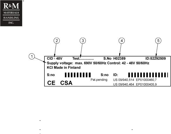
2.2Product description sticker
1.Supply voltage / Control Voltage 2.Unit type
3.Tested (year, week, tester) 4.Serial number
5.Product specific code
Unit types
Unit type |
Serial number |
Product specific code |
Control voltage |
CID-48V |
Hxxxxx |
ID: 52292509 |
42-48 VAC |
|
|
|
|
CID-115V |
Txxxxx |
ID: 52292510 |
110-230 VAC |
10/105
R&M Materials Handling, Inc. reserves the right to alter or amend the above information without notice.
R&M Materials Handling, Inc.
4501 Gateway Boulevard
Springfield, Ohio 45502
P.: (937) 328-5100
FAX: (937) 325-5319
3 Display unit
 t
t
 1
1  2
2  3
3
1.Red LED (Fault and Warning indication)
2.Orange LED (Tare load active)
3.Green LED (OK and Run indication)
The display unit shows in the large text field the actual or tared load. Also warning and fault messages are shown in the display. Parameter values can be read and set via display unit after a correct password has been given. Load information are displayed in a single row, other information are displayed in two rows. If display is inside the hoist-monitoring unit, the red display selection switch must be on the local position (up position).
Please note that the hoist-monitoring unit is designed for overload protection. The displayed load has an accuracy of approx. ±5% of the rated load and is thus not suitable to be used as a calibrated weighing scale.
3.1Push-buttons
On the display are four pushbuttons for navigating and programming.
ESC |
1. Zeroing of tare load. Press ESC button for three seconds. |
|
2. Moving from submenu to main menu and reject parameter changes |
||
|
1.Toggle between actual load (orange LED off) and tare load (orange LED on)
2.Scrolling down
1.Toggle between actual load (orange LED off) and tare load (orange LED on)
2.Scrolling up
ENT |
1. |
Entering the password level |
|
|
|
|
2. |
Selecting a menu and accept parameter changes |
3.2LEDs
There are three LEDs inside the display unit. The left red LED is for fault or warning indication. The orange or yellow LED in the centre is active when the tare load is selected. The right green LED is on when the hoist-monitoring unit is OK and blinks when the hoist is running.
Action / LED |
Red LED (Left) |
Orange LED (Centre) |
Green LED (Right) |
Illuminated continuously |
Fault |
Tare load value displayed |
OK, not running |
Blinking |
Warning and Service |
- |
OK, running |
Not illuminated |
OK |
Actual load value displayed |
Fault |
OK state means that the hoist control unit is working normally and no fault or error has been detected. When a driving output or the run feedback in inverter application is active, the green LED is blinking.
Warning means that a condition monitoring value exceeds the corresponding design value. Running the hoist is possible, but safe using is not guaranteed.
11/105
R&M Materials Handling, Inc. reserves the right to alter or amend the above information without notice.
R&M Materials Handling, Inc.
4501 Gateway Boulevard
Springfield, Ohio 45502
P.: (937) 328-5100
FAX: (937) 325-5319
Service-state means that a limit value set for the next service has been expired. This is indicated to the crane user, but the hoist can still be run normally.
Fault-state means that a serious problem has been detected. Running the hoist is restricted.
3.3Display information
3.3.1 Tare load / actual load mode
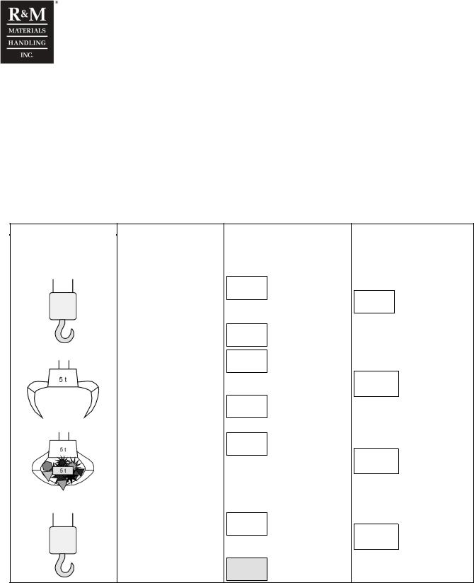
Tare load can be used when the crane is operated with a load-handling device, such as a grab or spreader. When no load-handling device is used, the tare load must be set to zero with empty hook. Considering a grab crane as example the table explains the differences between tare load and actual load. Press UP or DOWN button to toggle between tare and actual load.
|
|
Display information |
|
Hoist application |
Description |
Orange LED ON |
Orange LED OFF |
|
|
TARE LOAD |
ACTUAL LOAD |
10t grab without grab |
|
Displayed value depends on last |
|
|
zeroing. |
|
|
|
|
|
Only empty ropes or empty |
0.2 t |
|
|
|
|
|
0.2 t |
|
|
||
|
|
|
|
||
hook block. No load in the |
or zeroing press ESC for three sec. |
|
|
||
crane. |
|
|
|||
Display shows now |
|
|
|
||
|
|
|
|
||
|
|
|
|
|
|
|
0.0 t |
|
|
|
|
|
|
|
|
|
|
|
|
|
|
|
|
10 t grab crane |
5.0 t |
|
|
|
|
A grab is attached to the |
|
|
|
|
|
|
|
|
|
|
|
ropes. Grab weight is 5 tons. |
Press ESC button for three sec. |
5.2 t |
|
||
The grab is empty and not |
Display shows |
|
|||
loaded. |
|
|
|
|
|
0.0 t |
|
|
|
|
|
|
|
|
|
|
|
|
|
|
|
|
|
|
|
|
|
|
|
10 t grab crane |
Display shows |
|
|
|
|
|
|
|
|
||
|
5.0 t |
|
The payload + grap weight |
||
The grab is loaded with 5 tons |
|
|
|
|
|
|
|
10.2 t |
|
||
payload. |
This is the payload of the load- |
|
|||
|
|
||||
|
handling device. |
|
|
|
|
|
|
|
|
|
|
10 t grab crane without grab |
Last zeroing was made with 5 tons |
|
|
|
|
attached. Display shows |
|
|
|
||
|
|
|
|
||
|
|
|
|
|
|
Only empty ropes or empty |
-4.8 t |
|
|
|
|
|
0.2 t |
|
|||
hook block. No load in the |
|
|
|
||
Press ESC button for three sec. |
|
||||
crane. |
|
||||
|
|
|
|||
|
Display shows |
|
|
|
|
0.0t
When the display is in the load mode, the load can be tared (value set to zero) by pushing the ESC button about three seconds and after that display shifts into the tare load mode.
Tare function is made for each hoist individually; means tare command is not transferred to other units via CAN bus.
12/105
R&M Materials Handling, Inc. reserves the right to alter or amend the above information without notice.

R&M Materials Handling, Inc.
4501 Gateway Boulevard
Springfield, Ohio 45502
P.: (937) 328-5100
FAX: (937) 325-5319
3.3.2 Menu Mode
Pushing the ENT button in the tare or actual load display mode, shifts the display into the menu mode. A password is required in order to proceed. Pushing the ESC button returns to the actual load display.
3.3.3 Status mode
Status mode indicates all active faults, warnings and service warnings when applicable. The display shifts automatically into the status mode when a fault or warning occurs during power ON. If more than one fault or warning are active, all of them can be seen with arrow keys; active faults first, then warnings and service warnings. The active fault message remains visible until the fault disappears, or the message is removed by pushing the ENT button.
Display |
Description |
|
Fault |
Status display indicating active faults status. |
|
Fault name |
||
|
||
Warning |
Status display indicating active warnings status. |
|
Warning name |
||
|
||
Service |
Status display indicating active service status. |
|
Service name |
||
|
3.3.4 Sum load / solo hoist load mode
In multi-hoist applications, the display shows the summed tare load as the first display at power on. Toggling between the tared sum load, the actual sum load and the actual load of each connected hoist individually is done with the up and down buttons.
13/105
R&M Materials Handling, Inc. reserves the right to alter or amend the above information without notice.
R&M Materials Handling, Inc.
4501 Gateway Boulevard
Springfield, Ohio 45502
P.: (937) 328-5100
FAX: (937) 325-5319
3.4Menus
Monitoring items and parameters are presented in menus. The menus are accessible with passwords. The right to read and/or modify parameters within a menu depends on the selected password.
3.4.1 Moving in menus
Toggling between the menus is done with the up and down arrow buttons. When the desired menu has been selected, it is entered with the ENT-button. If there are submenus in the main menu, they are selected and entered in the same way as described above. Returning to the higher menu level is done with the ESC-button.
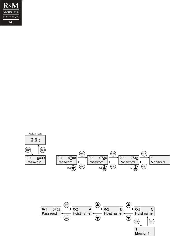
3.4.2 Password
When the ENT key is pushed the display shifts to the password request menu. With the ESC key or when an incorrect password is given, the display shifts back to the load display.
The first display of the password select menu shows four “zeros”, with the leftmost underlined. Pushing the up and down button will change the digit. The desired digit is selected with the ENT button, after which the next digit will be underlined. Repeat this procedure until the correct password is given. The display will now show the first menu “1 Monitor 1”.
(Example: Level 2 password “0732”)
3.4.3 Hoist selection (only multi-hoists)
In multi-hoist applications, where more then one unit are connected with the CAN-bus, the display will ask to select the desired unit (A, B, C, D or E) before the display shows the first menu. This way, each unit can be accessed via another unit. For example, all parameters and values of unit C can be displayed and modified via unit A.
When reading data from the display in multi hoist application, verify that you are reading the data from the correct device. The selected hoist is shown in the 0-2 display.
14/105
R&M Materials Handling, Inc. reserves the right to alter or amend the above information without notice.

R&M Materials Handling, Inc.
4501 Gateway Boulevard
Springfield, Ohio 45502
P.: (937) 328-5100
FAX: (937) 325-5319
3.5Parameters
3.5.1 Read-only parameters
Menu 1 (Monitor 1) and menu 2 (Monitor 2) contain read-only parameters. These menus will show the calculated and measured values of the solo hoist, connected to the selected unit.
3.5.2 Adjustable parameters
There are two sorts of adjustable parameters:
•Free adjustable (within the given limits)
•Choice from option list
When a parameter has to be adjusted, first select the desired parameter. Pushing the ENT button opens the parameter and the value can be adjusted. The free adjustable parameters will ask to adjust the digits one at the time, whereas other parameters will give the choice between a number of options.
15/105
R&M Materials Handling, Inc. reserves the right to alter or amend the above information without notice.
R&M Materials Handling, Inc.
4501 Gateway Boulevard
Springfield, Ohio 45502
P.: (937) 328-5100
FAX: (937) 325-5319
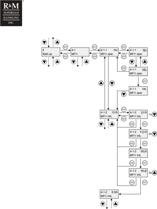
Example: selecting the MFI1 input to intermediate load function, with a load of 8.5 Tons.
3.6Remote Display
3.6.1 General
The display can be also located at a remote location, for example in the push button station, in the cubicle-door or in a crane driver cabin. In this way the crane operator can read load information directly from the display. All features as well as the parameter structure are the same as when the display would be located at the unit. The display in the remote location is a very effective tool for applications where the crane operator needs to have a load indication when handling loads.
Please note that the hoist-monitoring unit is designed for overload protection. The displayed load has an accuracy of approx. ±5% of the rated load and is thus not suitable to be used as a calibrated weighing scale.
16/105
R&M Materials Handling, Inc. reserves the right to alter or amend the above information without notice.

R&M Materials Handling, Inc.
4501 Gateway Boulevard
Springfield, Ohio 45502
P.: (937) 328-5100
FAX: (937) 325-5319
Connections and Display Selection Switch
A.Current loop to remote display
B.Display selection switch in down position for remote selection
If the display is in a remote location, the display is connected via a current loop with the hoist-monitoring unit. The current loop is between terminals 32 (CL-A) and 33 (CL-B). Because a current loop is not sensitive for electrical disturbances, it is not needed to use shielded cables for the display connection.
With the red display selection switch on top of the hoist-monitoring unit it is possible to switch between the display locations. The display selection switch must be in the down position to select the remote location active.
Remote display and display in the unit cannot work simultaneously.
17/105
R&M Materials Handling, Inc. reserves the right to alter or amend the above information without notice.

|
|
R&M Materials Handling, Inc. |
|
|
4501 Gateway Boulevard |
|
|
Springfield, Ohio 45502 |
|
|
P.: (937) 328-5100 |
|
|
FAX: (937) 325-5319 |
4 Parameters |
||
|
|
|
1 |
Monitor 1 |
Read only menu for condition monitoring values and |
|
|
measured values. |
1-1 |
Cond mon |
Condition monitoring menu |
1-1-1 |
SWP% |
Remaining Safe Working Period of the hoist in |
|
|
percentage, starting from 100%. |
1-1-2 |
Starts |
Total number of starts |
1-1-3 |
Run time |
Total running time |
1-1-4 |
Cycles |
Total number of hoisting cycles. |
1-1-5 |
Mean load |
Average of the handled load |
1-1-6 |
Br SWP% |
Remaining Safe Working Period of the brake in |
|
|
percentage. |
1-1-7 |
MFI1 RT |
Total hours of running time, when MFI1 input is closed. |
1-1-8 |
MFI1 ST |
Total amount of starts, when MFI1 input is closed. |
|
|
|
1-1-9 |
MFI2 RT |
Total hours of running time, when MFI2 input is closed. |
1-1-10 |
MFI2 ST |
Total amount of starts, when MFI2 input is closed. |
1-2 |
Measure |
Measurement menu |
|
|
|
1-2-1 |
Act. Load |
The measured actual load value. |
1-2-2 |
Temp 1 |
Temperature measured at thermistor input 1. |
1-2-3 |
Temp 2 |
Temperature measured at thermistor input 2. |
1-2-4 |
Supply L1 |
Line voltage of phase L1. |
1-2-5 |
Supply L2 |
Line voltage of phase L2. |
1-2-6 |
Supply L3 |
Line voltage of phase L3. |
1-2-7 |
Motor I1 |
Motor current of phase L1. |
1-2-8 |
Motor I2 |
Motor current of phase L2. |
1-2-9 |
Motor I3 |
Motor current of phase L3. |
1-2-10 |
Ain1 value |
Measured voltage at analogue input AIN1. |
1-2-11 |
Ain2 value |
Measured voltage at analogue input AIN2. |
1-2-12 |
Ain3 value |
Measured voltage at analogue input AIN3. |
|
|
|
1-2-13 |
Int. temp |
Internal temperature of the unit. |
1-2-14 |
Input |
Indicates the status of the inputs: HIN, LIN, FIN, MFI1 & |
|
|
MFI2. |
1-2-15 |
Output |
Indicates the status of the outputs: HOUT, LOUT, |
|
|
FOUT, RS & ROUT. |
1-2-16 |
Supply f |
Supply voltage frequency (50 or 60Hz) |
1-3 |
Min/Max |
Minimum / maximum value menu |
|
|
|
1-3-1 |
Min supply |
Minimum measured value of the supply line voltage |
|
|
RMS. |
1-3-2 |
Max supply |
Maximum measured value of the supply line voltage |
|
|
RMS. |
1-3-3 |
Min Int. T |
Minimum measured value of the internal temperature of |
|
|
the unit. |
1-3-4 |
Max Int. T |
Maximum measured value of the internal temperature of |
|
|
the unit. |
2 |
Monitor 2 |
Read only menu for advanced condition monitoring |
|
|
values and measured values. Accessible password |
|
|
level 3 |
2-1 |
SW version |
Software version of the unit |
2-2 |
RT slow |
Total run-time in slow speed |
2-3 |
RT fast |
Total run-time in fast speed |
2-4 |
No. OT |
Total number of hoist motor overtemperature incidents. |
2-5 |
No. OL |
Total number of overload incidents |
2-6 |
E-stops |
Total number of emergency stops incidents |
2-7 |
ST up |
Total number of starts in up direction |
2-8 |
ST down |
Total number of starts in down direction |
2-9 |
ST fast |
Total number of starts to fast speed (counts in two |
|
|
speed control only) |
2-10 |
Max ED |
Maximum value of the calculated ED percentage |
2-11 |
Over ED |
Counts the minutes when ED value has exceed the |
|
|
|
|
nominal ED value |
2-12 |
SWPRT% |
SWP% value calculated with hoist running time |
|
2-13 |
SRT3 |
Load sum with hoist running time, third power |
|
|
|
|
|
2-14 |
SRT8 |
Load sum with hoist running time, eight power |
|
2-15 |
SWPHC% |
SWP% value calculated with hoist cycles |
|
2-16 |
SL1 |
Load sum with hoist cycles, the first power (mean load) |
|
2-17 |
SL3 |
Load sum with hoist cycles, the third |
|
2-18 |
SL8 |
Load sum with hoist cycles, the eight power |
|
|
|
|
|
2-19 |
Power on |
The total power on time of the unit |
|
2-20 |
Temp Index |
Power on time of the unit, weighted with the unit’s |
|
|
|
|
temperature |
2-21 |
Max load |
Maximum measured value of the load |
|
3 |
|
Load setup |
Load calibration menu. Accessible password level 2 |
3-1 |
Cal. Motor |
Load calibration when the motor torque based load |
|
|
|
|
measurement is selecte. See chapter “Load |
|
|
|
calibration sequence with motor torque”. |
3-2 |
MC values |
Load calibration values for the motor torque method |
|
3-2-1 |
Load 1 |
The higher test load’s value |
|
3-2-2 |
Mhs1 |
Motor torque for hoisting in slow speed, with load. |
|
3-2-3 |
Mhf1 |
Motor torque for hoisting in fast speed, with load 1. |
|
3-2-4 |
Mls1 |
Motor torque for lowering in slow speed, with load 1. |
|
3-2-5 |
Mlf1 |
Motor torque for lowering in fast speed, with load 1, |
|
3-2-6 |
Load 2 |
The lower test load’s value. |
|
3-2-7 |
Mhs2 |
Motor torque for hoisting in slow speed, with load 2. |
|
3-2-8 |
Mhf2 |
Motor torque for hoisting in fast speed, with load 2. |
|
3-2-9 |
Mls2 |
Motor torque for lowering in slow speed, with load 2. |
|
3-2-10 |
Mlf2 |
Motor torque for lowering in fast speed, with load 2. |
|
3-3 |
Cal. Sens |
Load calibration when the sensor based load |
|
|
|
|
measurement is selected. See chapter “Load |
|
|
|
calibration sequence with the load sensor”. |
3-4 |
SC values |
Load calibration values for the load sensor method |
|
3-4-1 |
Load 1 |
The higher test load value. |
|
|
|
|
|
3-4-2 |
Input 1 |
The load measurement voltage in the analogue input |
|
|
|
|
Ain1 corresponding to the higher test load |
3-4-3 |
Load 2 |
The lower test load value |
|
3-4-4 |
Input 2 |
The load measurement voltage in the analogue input |
|
|
|
|
Ain1 corresponding to the lower load |
3-5 |
OL protect |
Set to “OFF” to temporarily by-pass of the overload |
|
|
|
|
protection |
4 |
|
Start-up |
Startmenu. Accessible password level 4 |
|
|||
|
|
|
|
4-1 |
MFI1 |
Multi-Functional Input 1 parameters |
|
|
|
|
|
4-1-1 |
MFI1 oper. |
Selects the function of MFI1: |
|
|
|
|
|
4-1-2 |
MFI1 IntL |
Intermediate load limit value |
|
|
|
|
|
4-1-3 |
MFI1 2OLL |
The second load |
|
4-1-4 |
MFI1 CintL |
Bridge intermediate load limit value. |
|
4-2 |
MFI2 |
Multi-Functional Input 2 parameters |
|
4-2-1 |
MFI2 oper. |
Selects the function of MFI2: |
|
4-2-2 |
MFI2 IntL |
The (second) intermediate load limit value |
|
4-2-3 |
1+2 IntL |
The third intermediate load limit value |
|
4-2-4 |
MFI2 2OLL |
The second load limit |
|
4-2-5 |
MFI2 CintL |
The (second) bridge intermediate load limit value |
|
4-2-6 |
1+2 CintL |
The third bridge intermediate load limit value |
|
|
|
|
|
18/105
R&M Materials Handling, Inc. reserves the right to alter or amend the above information without notice.

|
|
R&M Materials Handling, Inc. |
|
|
4501 Gateway Boulevard |
|
|
Springfield, Ohio 45502 |
|
|
P.: (937) 328-5100 |
|
|
FAX: (937) 325-5319 |
|
|
|
4-3 |
ROUT |
Relay output parameters |
4-3-1 |
ROUT oper. |
Selects the function of the relay output |
|
|
|
4-3-2 |
ROUT logic |
The operation logic of the relay: |
4-3-3 |
ROUT LoadX |
The load limit to switch the relay is entered here |
|
|
|
4-3-4 |
TempX meas |
The temperature measurement operation |
4-3-5 |
TempX lim |
The temperature limit |
|
|
|
4-4 |
T1 |
Temperature measurement channel 1 parameters |
4-4-1 |
T1 operat. |
Selects the function channel 1. |
4-5 |
T2 |
Temperature measurement channel 2 parameters |
4-5-1 |
T2 operat. |
Selects the function channel 1. |
4-6 |
AOUT |
Analogue output parameters |
|
|
|
4-6-1 |
AOUT oper. |
Selects the function of the analogue output |
4-6-2 |
Zero load |
Sets the voltage level with zero-load. Range 0…10V |
4-6-3 |
Nom. Load |
Sets the voltage level with rated load. Range 0…10V |
4-7 |
Load param |
Load calculation parameters |
4-7-1 |
Load meas. |
Selects the load calculation method: |
4-7-2 |
Load rate% |
Load increase rate for controlling the hoisting in two step |
|
|
control. |
4-7-3 |
R0_F |
Resistance of fast speed windings at temperature T0 |
4-7-4 |
R0_S |
Resistance of slow speed windings at temperature T0 |
4-7-5 |
T0 |
Resistance measuring temperature T0 |
4-7-6 |
Temp_slow |
Temperature measurement channel for the motor slow |
|
|
speed windings. |
4-7-7 |
Temp_fast |
Temperature measurement channel for the motor fast |
|
|
speed windings. |
4-7-8 |
C2F |
Coefficient 2 for fast speed |
4-7-9 |
C2S |
Coefficient 2 for slow speed |
4-7-10 |
C1F |
Coefficient 1 for fast speed |
4-7-11 |
C1S |
Coefficient 1 for slow speed |
4-7-12 |
ki |
Reduction factor for current transformer [A/V] |
4-7-13 |
Acc-t slow |
Acceleration time from stop to slow speed. |
4-7-14 |
Acc-t fast |
Acceleration time from slow speed to fast speed. |
4-8 |
Hoist ctrl |
The selection for the hoist control method |
4-9 |
Slack rope |
Slack rope function parameters |
4-9-1 |
SR select |
Selects the slack rope function |
4-9-2 |
Load limit |
The slack rope limit |
4-10 |
Single sup |
|
4-10-1 |
OT run ? |
Selects the action when the motor temperature exceeds |
|
|
the limit or when “Fault, Br wear” occurs |
4-10-2 |
OT limit |
When NTC type sensor is applied the limit value for the |
|
|
hoist motor overtemperature |
4-10-3 |
Supply sup |
Selects the supply voltage supervision. |
4-11 |
Comm hoist |
The settings for common hoisting (multi-hoist |
|
|
applications) |
4-11-1 |
Hoist cnt |
The number of units connected with CAN bus. Range: |
|
|
1…5 |
4-11-2 |
Run sup. |
Common hoisting supervision |
4-11-3 |
B OL |
Bridge overload protection |
4-11-4 |
B nom load |
Rated load of the bridge |
5 |
Service |
Startmenu. Accessible password level 5 |
5-1 |
S limits |
The limit values to indicate the need for service. |
5-1-1 |
S Run time |
Run time service limit |
5-1-2 |
S starts |
Service limit for the number of starts |
|
|
|
5-1-3 |
S SWP% |
Service limit for SWP% |
5-1-4 |
S Br SWP% |
Service limit for the hoist brake service life |
5-2 |
Fault log |
The logger for the latest fault situations, the number |
|
|
“n” indicates the number of faults in the logger |
5-2-1 |
F_”XXX” |
The latest fault. |
5-2-2 |
F_”XXX” |
The second latest fault. |
5-2-“n” |
F_”XXX” |
The “n” latest fault (highest number is 30). |
5-3 |
Reset log |
Resets the fault log by pushing the ENT button.. |
5-3 |
Reset log ? |
The reset action must be confirmed by pushing the ENT |
|
|
button once more |
6 |
Design |
Design values menu. Accessible password level 6 |
6-1 |
Hoist name |
Identifying letter of the hoist-monitoring unit, A, B, C, D |
|
|
or E. |
6-2 |
Unit No |
The serial number of the hoist. |
6-3 |
Class |
Mechanical class for the hoist according to the FEM / |
|
|
ISO duty classes. |
6-4 |
Nom. Load |
Rated load of the single hoist connected to the unit |
6-5 |
Nominal ED |
Rated ED value of the hoist |
6-6 |
Sp ratio |
Speed ratio. |
6-7 |
Max ST |
Maximum allowed number of starts |
6-8 |
Max E-stop |
Maximum allowed number of interrupted hoists |
|
|
(emergency stops) |
6-9 |
Max RT |
Maximum allowed run-time in hours |
6-10 |
D SRT3 |
Designed running hours, power three. |
6-11 |
D SRT8 |
Designed running hours, power eight. |
6-12 |
D SL3 |
Design constraint for hoisting cycles, power three |
6-13 |
D SL8 |
Design constraint for hoisting cycles, power eight |
6-14 |
MaxST MFI1 |
Max number of MFI1 starts. |
|
|
|
6-15 |
MaxRT MFI1 |
Max running time for MFI1. |
6-16 |
MaxST MFI2 |
Max number of MFI2 starts. |
6-17 |
MaxRT MFI2 |
Max running time for MFI2. |
6-18 |
Max Br |
Max number of braking actions. |
|
|
|
6-19 |
Max Control |
Max number of Control (starts) |
|
|
|
6-20 |
Password |
Set password level 1 (4digits). |
7 |
GO-setup |
GO-settings menu. Accessible password level 7 |
7-1 |
Cycles |
Number of hoisting cycles |
7-2 |
MFI1 RT |
MFI1 running time |
7-3 |
MFI1 ST |
MFI1 starts |
7-4 |
MFI2 RT |
MFI2 running time |
7-5 |
MFI2 ST |
MFI2 starts |
7-6 |
RT slow |
Run-time in slow speed |
7-7 |
RT fast |
Run-time in fast speed |
7-8 |
No. OT |
Number of hoist motor overtemperature incidents. |
7-9 |
No. OL |
Number of hoist overload incidents |
7-10 |
E-stops |
Number of emergency stops |
7-11 |
ST up |
Number of starts in up direction |
|
|
|
7-12 |
ST down |
Number of starts in down direction |
|
|
|
7-13 |
ST fast |
Number of starts to fast speed (two step control only) |
7-14 |
Max ED |
Maximum ED value |
|
|
|
7-15 |
Over ED |
Number of cases where ED value has exceeded the |
|
|
rated ED value |
7-16 |
SRT3 |
Load sum with hoist running time, third power |
7-17 |
SRT8 |
Load sum with hoist running time, eight power |
7-18 |
SL1 |
Load sum with hoist cycles, the first power (mean load) |
7-19 |
SL3 |
Load sum with hoist cycles, the third power |
7-20 |
SL8 |
Load sum with hoist cycles, the eight power |
7-21 |
Power on |
The total power on time for hoist control unit |
7-22 |
Temp Index |
The power on time weighted with the hoist control unit |
|
|
temperature |
7-23 |
Max load |
The maximum value of the measured load |
7-24 |
Br Count |
The brake wear counter. |
19/105
R&M Materials Handling, Inc. reserves the right to alter or amend the above information without notice.

R&M Materials Handling, Inc.
4501 Gateway Boulevard
Springfield, Ohio 45502
P.: (937) 328-5100
FAX: (937) 325-5319
4.1Passwords
The table below indicates the access to the menus with different password levels.
The display asks for the password when the ENT button is pushed in the main load display mode. If the given password does not match to any of the levels, the display returns to the main load display mode. If the given password matches to one of the levels, the user has access to the corresponding menus according to the table below.
Main menus |
Level 1 |
|
Level 2 |
Level 3 |
Level 4 |
|
Level 5 |
|
Level 6 |
Level 7 |
|
|
|
|
|
|
|
|
|
|
|
1 Monitor 1 |
X |
|
|
X |
X |
|
X |
|
X |
X |
2 Monitor 2 |
|
|
|
X |
X |
|
X |
|
X |
X |
3 Load Setup |
|
|
X |
|
X |
|
X |
|
X |
X |
|
|
|
|
|
|
|
|
|
|
|
4 Start-up |
|
|
|
|
X |
|
X |
|
X |
X |
5 Service |
|
|
|
|
|
|
X |
|
X |
X |
|
|
|
|
|
|
|
|
|
|
|
6 Design |
|
|
|
|
|
|
|
|
X |
X |
7 GO-setup |
|
|
|
|
|
|
|
|
|
X |
|
|
|
|
|
|
|
|
|
|
|
|
|
|
|
|
|
|
|
|
|
|
Passwords for different levels |
|
|
|
|
|
|
|
|
|
|
|
|
|
|
|
|
|
|
|
|
|
Level |
Password |
|
Note |
|
|
|
|
|
|
|
Level 1 |
Parameter |
|
Given with the parameter, 6–20 Password |
|
|
|
|
|||
|
|
|
|
|
|
|||||
Level 2 |
0732 |
|
Fixed value, can only calibrate the load measurement |
|
|
|||||
Level 3 |
5201 |
|
Fixed value, used to read the monitoring values |
|
|
|
|
|||
|
|
|
|
|
|
|||||
Level 4 |
8124 |
|
Fixed value, all menus up to input/output settings and calibration |
|
|
|||||
Level 5 |
5029 |
|
Fixed value, all menus up to service menu |
|
|
|
|
|||
|
|
|
|
|
|
|
|
|||
Level 6 |
9822 |
|
Fixed value, all menus up to design limit values |
|
|
|
|
|||
|
|
|
|
|
|
|
|
|||
Level 7 |
2180 |
|
Fixed value, access to all parameters |
|
|
|
|
|||
20/105
R&M Materials Handling, Inc. reserves the right to alter or amend the above information without notice.
R&M Materials Handling, Inc.
4501 Gateway Boulevard
Springfield, Ohio 45502
P.: (937) 328-5100
FAX: (937) 325-5319
5 Basic Functions
5.1General
The basic functions assure the safe functioning of the hoist. The hoist-monitoring unit constantly performs a number of checks to determine if all conditions are safe in order to proceed the motion. In case the hoist-monitoring unit detects a potentially unsafe situation, the motion will be stopped. Depending on the kind of fault, both hoisting and lowering is prevented or in other cases driving in the opposite direction is allowed.
In addition to the basic functions, a wide scale of optional functions can be installed. Refer to the section “Optional functions” or contact a manufacturer’s representative for further details.
The basic functions of the hoist-monitoring unit are:
•Overload protection
•Hoist motor overtemperature supervision
•Supply phase supervision
•Run and fault supervision
•Starting and stopping through slow speed
•Sudden load increase supervision
The basic functions are factory set according to specific hoist and customer’s demand.
It is possible that few basic functions can’t be used in every hoist. (e.g. Insulated network, inverter drive)
The additional optional functions of the hoist-monitoring unit are:
•Lifetime counters
•Remote display
•Multicare
•Multi function input Options
•Potentional Free Relay Options
•Analog Output
When during run one of the supervised safety features value exceeds the limit, the unit will stop the motion. Re-starting is only possible after the reason for the fault is terminated. Note that some faults are direction dependent and running in the opposite direction will terminate the fault. Refer to the sections that describe the supervisions for details.
The hoist-monitoring unit is equipped with two LEDs that provide operational information as follows:
Action / LED |
Green LED |
Red LED |
Illuminated continuously |
OK, not running |
Fault |
|
|
|
Blinking |
OK, running |
Warning |
|
|
|
Not illuminated |
Fault |
OK |
OK state means that the hoist control unit is working normally and no fault or error has been detected. Running the hoist is possible.
Warning means that a condition-monitoring value has exceeded the design value. Running the hoist is possible, but safe operation can not be guaranteed.
21/105
R&M Materials Handling, Inc. reserves the right to alter or amend the above information without notice.

R&M Materials Handling, Inc.
4501 Gateway Boulevard
Springfield, Ohio 45502
P.: (937) 328-5100
FAX: (937) 325-5319
Fault means that one (or more) of the supervised safety features values exceeds the limit. Running the hoist is restricted.
For Run or Fault supervision, it is possible to connect an external indication device like a horn or lamp to the relay output. Relay output must be programmed to the desired function “OK” or “Ready”
5.2Overload protection
The overload protection can be done in two ways, either with motor torque calculation or by using a load sensor. Regardless which system is used, the hoist-monitoring unit will prevent the hoisting motion when the measured load exceeds 110% of the rated load for a period of time. A filtering delay is built in to assure trouble-free lifting of a rated load. The overload protection is reset when the measured load decreases to 80% of the rated load.
The overload protection reacts faster than the display updates the measured values. Therefore it may happen that the movement is stopped although the display indicates a load less than 110% of the rated load.
Overload level |
Filtering time |
Run-down time |
140% |
60 ms |
~100 ms |
125% |
200 ms |
~250 ms |
110% |
1000 ms |
~1050 ms |
The motor torque calculation system uses the motor voltage, current and temperature to calculate the motor torque and converts this into load information. This system cannot be used in combination with frequency converters, and can only measure the load when the motor is running. In addition to the overload protection, the hoist-monitoring unit also supervises the brake. When the calculated load value descends under -50% of the rated load during lowering, it indicates that the brake did not open. Lowering the hook is prevented, but lifting is still allowed.
Motors driven by a frequency converter are always equipped with a load sensor for load measurement.
Systems using a strain gauge type of sensor are also equipped with a load sensor amplifier to amplify the signal coming from the sensor. In case a Hall-type of sensor is used, the load sensor amplifier is not needed.
Param. |
Name |
Value |
Description |
|
|
|
|
|
|
4-7 |
Load param |
|
Load calculation parameters |
|
|
|
|
|
|
|
|
|
Selects the load calculation method: |
|
4-7-1 |
Load meas. |
|
NU |
Not used, the display show all time to 0,0t |
|
|
|
||
|
Motor |
Motor torque calculation. Refer to chapter “Overload protection – Motor torque” of this manual |
||
|
|
|
||
|
|
|
Sens. |
Load sensor measurement . Refer to chapter “Overload protection – Load sensor” of this manual |
|
|
|
|
|
Load measurement tolerance is ±10% of nominal load by use motor torque calculation system and load measurement tolerance is ±5% of nominal load by use load sensor.
22/105
R&M Materials Handling, Inc. reserves the right to alter or amend the above information without notice.

R&M Materials Handling, Inc.
4501 Gateway Boulevard
Springfield, Ohio 45502
P.: (937) 328-5100
FAX: (937) 325-5319
5.3Hoist motor overheating supervision
To prevent the hoisting motor from burning up, the hoist-monitoring unit will constantly measure the internal temperature of the motor. The motor is therefore equipped with temperature sensors; PTCthermistors, NTC-thermistors or Bi-metal switches (Klixons). The hoist-monitoring unit can be programmed to either prevent both hoisting and lowering (default), or only the hoisting motion.
PTC-thermistor connections
PTC-thermistors are commonly used in most of the motors in the past. PTC-thermistors will rapidly increase their resistance when the measured temperature exceeds the limit. The maximum allowed temperature depends on the motor and is determined by the used thermistors. The hoist-monitoring unit will detect over temperature when the resistance of the PTC exceeds 4.0kOhm.
Bi-metal switches are mounted on the motor stator windings. Bi-metal switches operate as thermal-switches and will open up the contact when the measured temperature exceeds the limit. The maximum allowed temperature depends on the motor and is determined by the used Bi-metal switches. The hoist-monitoring unit will detect overtemperature when the resistance exceeds 4.0kOhm (thus open contact).
In practice, PTC-thermistors and Bi-metal switches operate in the same way. The hoist-monitoring unit stops the motion when the resistance of the temperaturemeasuring device exceeds 4.0kOhm.
NTC-thermistors connections
NTC-thermistors are used when motor torque calculation is the load measurement method. NTC-thermistors will decrease their resistance in an almost linear relation to temperature increase. The actual motor temperature is accurately measured with NTC-thermistors and the hoistmonitoring unit will stop the motion in case the resistance of the temperature-measuring device drops below the preset value.
23/105
R&M Materials Handling, Inc. reserves the right to alter or amend the above information without notice.

R&M Materials Handling, Inc.
4501 Gateway Boulevard
Springfield, Ohio 45502
P.: (937) 328-5100
FAX: (937) 325-5319
Thermistors operating curve
|
NTC |
PTC |
Bi-metal |
|
40 |
|
|
|
35 |
|
|
|
30 |
|
|
|
25 |
|
|
kohm |
20 |
|
|
|
|
|
|
|
15 |
|
|
|
10 |
|
|
|
5 |
|
|
|
0 |
|
Over temperature |
|
Motor Temperature |
||
|
|
||
NTC and PTC: The temperature sensor’s cable must be shielded if the cable between the unit and the temperature sensors is longer than 10m. The cable shield is connected to the ground of the hoist. It is recommended to use 360 degrees shield clamps to carry out the grounding!
Bi-metal: It is recommended to use a supplementary relay between the unit and the thermistor. In that case there is no need for a shielded cable and possible disturbance is limited to the minimum.
In case third party motors are used, please consult with the manufacturer of the motor for thermistor details.
Motors without thermistors must be protected against overheating by other means, e.g. a motor protection switch.
24/105
R&M Materials Handling, Inc. reserves the right to alter or amend the above information without notice.

R&M Materials Handling, Inc.
4501 Gateway Boulevard
Springfield, Ohio 45502
P.: (937) 328-5100
FAX: (937) 325-5319
5.3.1 Hoist motor overheating supervision instructions
Param. |
Name |
Description |
|
|
|||
4-4 |
T1 |
Temperature measurement channel 1 parameters |
|||||
|
|
|
|
|
|
|
|
4-4-1 |
T1 operat. |
Selects the function of temperature measurement channel 1: |
|||||
|
|
|
NU |
Not used |
Motor without thermistors or only one sensor that is connected to the |
||
|
|
|
temperature input 2. |
||||
|
|
|
|
|
|
||
|
|
|
PTC |
Motor thermistor or |
Two speed motors typically only have one set of thermistors, for both low speed |
||
|
|
|
Bimetal thermal switch |
and high speed windings. |
|||
|
|
|
|
|
|||
|
|
|
Bwear |
Brake wear sensor |
See section Hoist BrakeWear supervision |
||
|
|
|
A NTC |
Type A NTC sensor |
Determines the type of thermistors in the low speed windings, connected to the |
||
|
|
|
B NTC |
Type B NTC sensor |
temperature input 1 |
||
|
|
|
|
|
|||
|
|
|
|
|
|
Manufacturer’s hoisting motors used in motor-torque calculation overload |
|
|
|
|
C NTC |
Type C NTC sensor |
|||
|
|
|
systems are as a standard equipped with type B NTC thermistors |
||||
|
|
|
|
|
|
||
|
|
|
|
|
|
|
|
Param. |
Name |
Description |
|
|
|||
4-5 |
T2 |
Temperature measurement channel 2 parameters |
|||||
|
|
|
|
|
|
||
4-5-1 |
T2 operat. |
Selects the function of temperature measurement channel 2: |
|||||
|
|
|
NU |
Not used |
Motor without thermistors or only one sensor that is connected to the |
||
|
|
|
temperature input 1. |
||||
|
|
|
|
|
|
||
|
|
|
PTC |
Motor thermistor or |
Two speed motors typically only have one set of thermistors, for both low speed |
||
|
|
|
Bimetal thermal switch |
and high speed windings. |
|||
|
|
|
|
|
|||
|
|
|
Bwear |
Brake wear sensor |
See section Hoist BrakeWear supervision |
||
|
|
|
A NTC |
Type A NTC sensor |
Determines the type of thermistors in the low speed windings, connected to the |
||
|
|
|
B NTC |
Type B NTC sensor |
temperature input 1 |
||
|
|
|
|
|
|||
|
|
|
|
|
|
Manufacturer’s hoisting motors used in motor-torque calculation overload |
|
|
|
|
C NTC |
Type C NTC sensor |
|||
|
|
|
systems are as a standard equipped with type B NTC thermistors |
||||
|
|
|
|
|
|
||
|
|
|
|
|
|
|
|
Param. |
|
Value |
|
Description |
|
Note |
|
4-10 |
|
|
|
|
|
|
Accessible with password 4: 8124 |
Single sup |
|
|
|
|
|
|
|
4-10-1 |
|
No / Down |
Hoisting and lowering is prevented when the |
If, for safety reasons, local legislation or customer demands, |
|||
OT run ? |
|
|
|
overtemperature supervision trips. |
lowering the load is required when the temperature supervision |
||
|
|
|
|
|
|
has tripped, set this parameter to: “Down” |
|
|
|
|
|
|
|
|
|
|
|
|
|
|
|
||
4-10-2 |
|
150C |
|
Sets the tripping level of the overtemperature |
Consult with the motor data sheets for the maximum allowed |
||
OT limit |
|
|
|
supervision in degrees Celsius, steps of one |
temperature for the motor. Default for manufacturer’s squirrel |
||
|
|
|
degree. Only with NTC-thermistor. |
|
|||
|
|
|
|
cage motors: 150°C |
|||
25/105
R&M Materials Handling, Inc. reserves the right to alter or amend the above information without notice.
R&M Materials Handling, Inc.
4501 Gateway Boulevard
Springfield, Ohio 45502
P.: (937) 328-5100
FAX: (937) 325-5319
5.4Supply voltage phase supervision
The supply voltage phase supervision consists of two functions:
-Missing supply phase detection
-Incorrect supply phase order
The three supply voltage phases are wired to the hoist-monitoring unit. Each time the unit is powered up, the phase order is checked. The unit will continuously measure the existing of all three phases.
In case wrong direction of hoisting occurs (reversed phase condition), note that the two input power wires are reversed at terminal X2A!
5.4.1 Supply phase supervision instructions
Supply phase supervision parameters
Param. |
Value |
Description |
Note |
4-10 |
|
|
Accessible with password 4: 8124 |
Single sup |
|
|
|
|
|
|
|
4-10-3 |
Yes |
Switches the supply phase supervision on. |
When the hoist monitoring-unit is connected in insulated or high |
|
|
|
impedance grounded network, or when the supply mains are not |
|
|
|
connected (i.e. inverter use), the setting must be “No”. |
26/105
R&M Materials Handling, Inc. reserves the right to alter or amend the above information without notice.
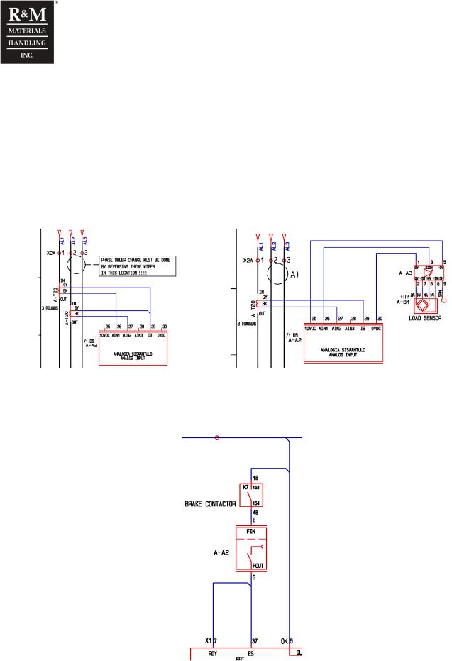
R&M Materials Handling, Inc.
4501 Gateway Boulevard
Springfield, Ohio 45502
P.: (937) 328-5100
FAX: (937) 325-5319
5.5RUN and fault supervision
The hoisting and lowering request from the control station will come as an input to the hoist-monitoring unit. Before the hoist can start the requested motion, the hoist-monitoring unit checks if it is safe to proceed. If no limitations are detected, the hoist-monitoring unit will activate the requested output and movement will start. The unit monitors a feedback signal. When the feedback signal drops during running, the motion will stop immediately. During the starting sequence, the feedback signal must be on within 200ms in contactor control, and within 800ms in inverter control.
2 Speed Hoisting: Unit monitors a feedback signal from a current transformer to analog input 2. The current transformer measures the input current to the motor in 2 speed hoisting. During the starting sequence, the feedback signal must be on within 200ms in contactor control. When the feedback signal drops during running, the motion will stop immediately.
2 Speed, load measurement by motor |
2 Speed, load measurement by sensor |
When the unit supervises a hoist inverter application a brake contact from AK7 is connected to the FIN input, terminal 8, to be a brake open feedback signal. If the brake contactor does not energize during start or de-energizes during hoisting (initiated by a fault or due to brake failure) the unit will disconnect control voltage from the FOUT signal output, terminal 3, feeding the ES and RDY inputs of the inverter. During the starting sequence, in inverter control, the feedback signal at FIN must be on within 800ms.
27/105
R&M Materials Handling, Inc. reserves the right to alter or amend the above information without notice.
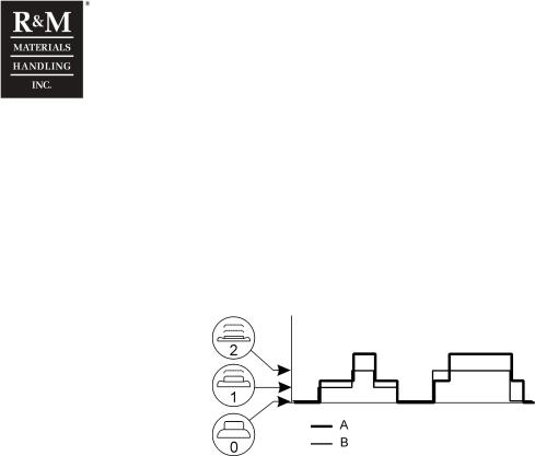
R&M Materials Handling, Inc.
4501 Gateway Boulevard
Springfield, Ohio 45502
P.: (937) 328-5100
FAX: (937) 325-5319
5.6Starting and stopping through slow speed (2 speed application only)
Starting the motor directly in high speed will cause a high starting current that heats up the motor quite rapidly. To prevent the motor from overheating, the hoist-monitoring unit will always start the motion in slow speed. After a short period of time, the hoist-monitoring unit allows driving in fast speed when requested.
Stopping the motion directly from high speed will cause excessive brake wear. To protect the brake lining material, the hoist-monitoring unit will initiate slow speed for a brief moment, before the mechanical brake is closed.
This function can only be activated in two-speed systems
A.Speed
B.Position of pushbutton (0, 1, 2)
5.6.1Starting and stopping through slow speed instructions
Starting and stopping through slow speed parameters
Param. |
Value |
Description |
Note |
4-7Load param |
|
Load calculation menu |
Accessible with password 4: 8124 |
4-7-13 |
0.20s |
Acceleration time from stop to slow speed 0.00s – 1.00s |
See description below |
4-7-14 |
0.30s |
Acceleration time from slow speed to fast speed 0.00s – 1.00s |
See description below |
The parameters 4-7-13 and 4-7-14 have the following functions:
•During acceleration from zero to slow speed and deceleration from slow speed to zero, the unit will not calculate or supervise the overload protection and current measurement for a period of time determined by parameter 4-7-13.
•During acceleration from slow speed to fast speed and deceleration from fast speed to slow speed, the unit will not calculate or supervise the overload protection and current measurement for a period of time determined by parameter 4-7-14.
•The above function prevents the overload from tripping during the acceleration and deceleration moment, especially in two-step systems with motor-torque calculation based overload protection, since the starting currents are momentarily quite high.
•When accelerating from zero directly to fast speed, the motion starts in slow speed for a period determined by par. 4-7-13.
•When decelerating from fast speed to slow speed, the unit will keep the fast speed active for a period determined by par. 4-7-14.
•When decelerating from fast speed directly to zero, the unit will activate the slow speed for a fixed period of 250ms (not adjustable by parameters!).
The above function prevents the use called as “inching”, “jogging” or “tipping” operation.
Once the slow speed output is activated, it remains active for 250ms, even if the input command drops off within this time. This prevents the directional contactors to drop off during the high starting
currents.
28/105
R&M Materials Handling, Inc. reserves the right to alter or amend the above information without notice.
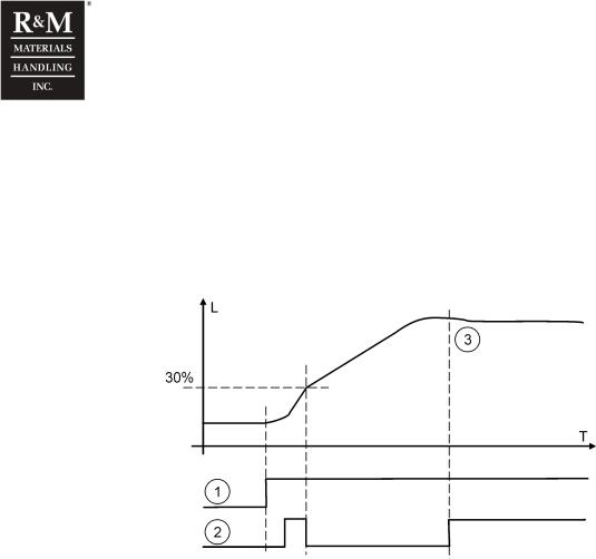
R&M Materials Handling, Inc.
4501 Gateway Boulevard
Springfield, Ohio 45502
P.: (937) 328-5100
FAX: (937) 325-5319
5.7Sudden load increase supervision
In case the hoist-monitoring unit measures a sudden load increase when driving upwards in high speed, the unit will control the hoist to low speed. A sudden load increase is considered when the load exceeds 30% of the rated load of the hoist within 200ms. High speed hoisting is allowed again when the load increase in the last 200ms is less than the preset value, determined by parameter 4-7-2.
The function is completely reset when the measured load is less than 10% of the rated load of the hoist. The function has no effect when the load is bigger than 30% of the rated load of the hoist. Sudden load increase may occur e.g. due to jerky movements or starts in high speed.
L. Load
T. Time
1.First speed
2.Second speed
3.Load increase stops
This function can only be activated in two-speed application and hoist has no effect when hoisting in low speed. Sudden load increase supervision is only activate with loads below 30% of rated load and is activated only once.
5.7.1Sudden load increase supervision instructions
Sudden load increase supervision parameters
Param. |
Value |
Description |
Note |
4-7 |
|
Load calculation menu |
Accessible with password 4: 8124 |
Load param |
|
|
|
4-7-2 |
10 |
Load increase rate for controlling the hoisting in two step control, speed |
0% means that the function is not applied |
Load rate% |
|
change to fast speed is allowed when actual load change within 200ms < |
10% is the factory default |
|
|
parameter 4-7-2. |
|
|
|
Setting range: 0…10%, steps of 1% |
|
A small value makes the hoist to drive in slow speed for a longer period, to ensure that the load is stabilised (not stuck to the unloading platform etc. and no more vibrations caused by the ropes and/or other mechanics).
A larger value (maximum 10) allows faster acceleration to fast speed.
29/105
R&M Materials Handling, Inc. reserves the right to alter or amend the above information without notice.

R&M Materials Handling, Inc.
4501 Gateway Boulevard
Springfield, Ohio 45502
P.: (937) 328-5100
FAX: (937) 325-5319
6 Monitoring Items
6.1General
In order to read the monitoring items and to program the unit, the hoist-monitoring unit is equipped with a display. The monitoring items of the hoist-monitoring unit consist of variable read-only values. These monitoring items are of great advantage when efficiently planning maintenance, preventive repairs, troubleshooting and general overhauls. In addition, the monitoring values will accurately show the usage of the hoist.
The values are stored in the memory of the hoist-monitoring unit. The stored values remain also during power-off situations. After power-off situation the previously stored values are taken into account when new values are calculated.
The condition monitoring items can only be read after a correct password has been given. The manufacturer will provide a personal password with each delivery that has been acquired with this option.
1 |
Monitor 1 |
|
Read only menu for condition monitoring values and measured values. |
|
|
Accessible with the customer’s password. |
|||
|
|
|
||
|
|
|
|
|
Param. |
Name |
Value |
Description |
|
|
|
|
|
|
1-1 |
Cond mon |
|
Condition monitoring menu |
|
|
|
|
|
|
1-1-1 |
SWP% |
“n” % |
Remaining Safe Working Period of the hoist in percentage, starting from 100%. When the SWP |
|
counter descends to 0% (or even negative), a General Overhaul must be carried out. |
||||
|
|
|
||
|
|
|
|
|
1-1-2 |
Starts |
“n” |
Total number of starts of the hoist in either up or down direction. *1) |
|
1-1-3 |
Run time |
“n” h |
Total running time of the hoist in hours. *2) |
|
|
|
|
|
|
1-1-4 |
Cycles |
“n” |
Total number of hoisting cycles. *1). The number increases by one, when a load value increase |
|
more than 20% of the rated load is lifted. |
||||
|
|
|
||
1-1-5 |
Mean load |
“n.n” t |
Average of the handled load during the recorded cycles. |
|
1-1-6 |
Br SWP% |
“n” % |
Remaining Safe Working Period of the brake in percentage. The SWP for the brake is calculated |
|
according to the number of Starts and E-stops (also stops at limit switch). |
||||
|
|
|
6.2Primary monitoring items
The primary monitoring items are according to the ISO and FEM regulation. Depending on the hoist duty class, the hoist is given an initial Safe Working Period (SWP). The SWP counts down according to a calculation, which includes the running time with a certain load. Also the total run-time (independent on the load) and the amount of starts are directly related to the hoist’s duty class and theoretical lifetime.
The primary monitoring items, related to the FEM and ISO regulations are:
-Hoist Safe Working Period counter (SWP%)
-Starts counter
-Run Time counter
Monitoring items can only be read if the hoist-monitoring unit is equipped with a display, either mounted on the unit or in the pushbutton station.
30/105
R&M Materials Handling, Inc. reserves the right to alter or amend the above information without notice.
 Loading...