


English
Original instructions
SERVICE MANUAL FOR TRAVELING INVERTER
Service Manual for DMCS 007F
- - - -
SUPDOC_SM_DMCS019-0.ORD 16.11.2010
C_SM_DMCS0190100-0 PS02379 16.11.2010

R&M Materials Handling, Inc.
4501 Gateway Boulevard
Springfield, Ohio 45502
P.: (937) 328-5100
FAX: (937) 325-5319
Table of contents
1 |
DESCRIPTION OF THE INVERTER.................................................................................................. |
3 |
|
|
1.1 |
Connections............................................................................................................................................ |
3 |
|
1.2 |
Technical characteristics......................................................................................................................... |
3 |
|
1.3 |
Normal operation .................................................................................................................................... |
4 |
|
1.4 |
Status indication leds (green and red) ..................................................................................................... |
4 |
|
1.5 |
Compact brake motors............................................................................................................................ |
4 |
|
1.6 |
Programming switches............................................................................................................................ |
4 |
|
1.7 |
The EMC requirements ........................................................................................................................... |
5 |
|
1.7.1 EMC filter connection to inverter for trolley travelling............................................................................ |
5 |
|
|
1.7.2 EMC filter connection to inverter for bridge travelling. .......................................................................... |
5 |
|
2 |
DESCRIPTION OF CONTROL MODES............................................................................................. |
6 |
|
|
2.1 |
MS2-control (S4-1=OFF)......................................................................................................................... |
6 |
|
2.2 |
EP2-control (S4-1=ON)........................................................................................................................... |
6 |
3 |
FAULT CODES, TROUBLESHOOTING............................................................................................. |
7 |
|
4 |
PROGRAMMING OF THE APPLICATION PARAMETERS ................................................................ |
8 |
|
|
4.1 |
Minimum speed, maximum speed and ramp time.................................................................................... |
8 |
|
4.1.1 Acceleration and deceleration ramp..................................................................................................... |
8 |
|
|
4.2 |
Selection of the motor type...................................................................................................................... |
9 |
2/9 |
R&M Materials Handling, Inc. reserves the right to alter or amend the above information without notice. |
R&M Materials Handling, Inc.
4501 Gateway Boulevard
Springfield, Ohio 45502
P.: (937) 328-5100
FAX: (937) 325-5319
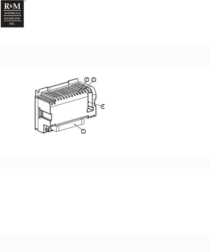
1 DESCRIPTION OF THE INVERTER
There are high voltages inside the inverter (including the programming switches). Wait for at least three minutes after the supply voltage has been switched off before any service actions.
DMCS007
1. Terminal X1
2. Red led (fault)
3. Green led (ok)
4. Programming switches
c_fcmo1b
1.1Connections
All connections are made to terminal block X1 as follows:
Crane power supply conductor rail must have double collectors.
|
|
DMCS007 |
Nbr |
Name |
Description |
1 |
PE |
Protective earth. |
|
|
|
2 |
L1 |
Mains, phase 1. 380-480V 50/60Hz. |
3 |
L2 |
Mains, phase 2. 380-480V 50/60Hz. |
|
|
|
4 |
L3 |
Mains, phase 3. 380-480V 50/60Hz. |
5 |
U |
Motor, phase 1. |
6 |
V |
Motor, phase 2. |
7 |
W |
Motor, phase 3. |
8 |
S1 |
Drive command. Direction 1. 48 or 115V 50/60Hz |
|
|
|
9 |
S2 |
Drive command. Direction 2. 48 or 115V 50/60Hz |
10 |
SP2/AP |
Speed 2 / Acceleration command. 48 or 115V 50/60Hz |
11 |
ON |
Control voltage, neutral. |
|
|
|
Standard duty resistor must be disconnected when heavy duty resistor DMHR01F90 is connected to terminals R+ and R−.
1.2Technical characteristics
Technical data |
DMCS007 |
|
|
Power range |
0.75kW |
Supply voltage |
380 - 480 VAC -10%/+5% |
Nominal supply frequency |
48 – 62 Hz |
Nominal current |
2.4A |
|
|
Digital control |
S1, S2, DI3 |
Max output voltage |
Equal to supply voltage |
|
|
Control voltage range |
48 VAC/115 +/- 10%. If control voltage is 230VAC, front resistors (15k,2W) have to be |
|
connected to digital inputs |
Output |
|
Ambient temperature |
-10oC to 50oC |
3/9 |
R&M Materials Handling, Inc. reserves the right to alter or amend the above information without notice. |
 Loading...