

Page 1

-
3
RKC INSTRUMENT INC.
®
Three-phase Thyristor Unit
400 V AC Type
THW
Instruction Manual
IMR01V02-E1
Page 2

Company names and product names used in this manual are the trademarks or registered trademarks of
the respective companies.
All Rights Reserved, Copyright 2005, RKC INSTRUMENT INC.
Page 3

t
Thank you for purchasing this RKC instrument. In order to achieve maximum performance and ensure
proper operation of your new instrument, carefully read all the instructions in this manual. Please
place this manual in a convenient location for easy reference.
SYMBOLS
WARNING
CAUTION
!
An external protection device must be installed if failure of this instrument
could result in damage to the instrument, equipment or injury to personnel.
: This mark indicates precautions that must be taken if there is danger of electric
shock, fire, etc., which could result in loss of life or injury.
: This mark indicates that if these precautions and operating procedures are no
taken, damage to the instrument may result.
: This mark indicates that all precautions should be taken for safe usage.
: This mark indicates important information on installation, handling and operating
procedures.
: This mark indicates supplemental information on installation, handling and
operating procedures.
: This mark indicates where additional information may be located.
WARNING
!
All wiring must be completed before power is turned on to prevent electric
shock, fire or damage to instrument and equipment.
This instrument must be used in accordance with the specifications to
prevent fire or damage to instrument and equipment.
This instrument is not intended for use in locations subject to flammable or
explosive gases.
Do not touch the high-voltage sections such as power supply terminals,
power supply lines and input/output terminals. If touched, electric shock or
injury may result.
Do not enter the hand into the opening of this instrument. If entered, electric
shock or injury may result.
RKC is not responsible if this instrument is repaired, modified or
disassembled by other than factory-approved personnel. Malfunction can
occur and warranty is void under these conditions.
IMR01V02-E1
i-1
Page 4

CAUTION
This is a Class A instrument. In a domestic environment, this instrument may cause radio
interference, in which case the user may be required to take adequate measures.
This instrument is protected from electric shock by reinforced insulation. Provide
reinforced insulation between the wire for the input signal and the wires for instrument
power supply, source of power and loads.
Be sure to provide an appropriate surge control circuit respectively for the following:
- If input/output or signal lines within the building are longer than 30 meters.
- If input/output or signal lines leave the building, regardless the length.
This instrument is manufactured on the assumption that it is mounted within a control
panel. All high-voltage connections such as power supply terminals must be enclosed in
the control panel to avoid electric shock by operating personnel.
All precautions described in this manual should be taken to avoid damage to the
instrument or equipment.
All wiring must be in accordance with local codes and regulations.
Always use this product at the rated power supply voltage, load current and power
frequency.
All wiring must be completed before power is turned on to prevent electric shock,
instrument failure, or incorrect action.
To prevent instrument damage or failure, protect the power line and the input/output lines
with a protection device such as fuse, etc.
If this product is used for phase control, higher harmonic noise may be generated.
Therefore in this case, take such measures as installing an isolation transformer and
separating the power line from the high-voltage line for load drive.
Prevent metal fragments or lead wire scraps from falling inside instrument case to avoid
electric shock, fire or malfunction.
Tighten each terminal screw to the specified torque found in the manual to avoid electric
shock, fire or malfunction.
For proper operation of this instrument, provide adequate ventilation for heat dispensation.
Do not connect wires to unused terminals as this will interfere with proper operation of the
instrument.
Turn off the power supply before cleaning the instrument.
Do not use a volatile solvent such as paint thinner to clean the instrument. Deformation or
discoloration will occur. Use a soft, dry cloth to remove stains from the instrument.
To avoid damage to instrument display, do not rub with an abrasive material or push front
panel with a hard object.
NOTICE
This manual assumes that the reader has a fundamental knowledge of the principles of electricity,
process control, computer technology and communications.
The figures, diagrams and numeric values used in this manual are only for purpose of illustration.
RKC is not responsible for any damage or injury that is caused as a result of using this instrument,
instrument failure or indirect damage.
RKC is not responsible for any damage and/or injury resulting from the use of instruments made by
imitating this instrument.
Periodic maintenance is required for safe and proper operation of this instrument. Some
components have a limited service life, or characteristics that change over time.
Every effort has been made to ensure accuracy of all information contained herein. RKC makes no
warranty expressed or implied, with respect to the accuracy of the information. The information in
this manual is subject to change without prior notice.
No portion of this document may be reprinted, modified, copied, transmitted, digitized, stored,
processed or retrieved through any mechanical, electronic, optical or other means without prior
written approval from RKC.
i-2
IMR01V02-E1
Page 5

CONTENTS
1. OUTLINE .............................................................................. 1
1.1 Checking the Product ......................................................................................2
1.2 Parts Description ............................................................................................. 4
2. MOUNTING ........................................................................... 6
2.1 Mounting Environment.....................................................................................6
2.2 Mounting Cautions...........................................................................................7
2.3 Dimensions......................................................................................................8
2.4 Mounting Procedures ....................................................................................11
Page
3. WIRING ............................................................................... 12
3.1 Circuit Block Diagram ....................................................................................12
3.2 Wiring of Main Circuit ....................................................................................13
3.3 Wiring of the Step-Down Transformer ...........................................................15
3.4 Wiring of Controller (Auto Mode) ................................................................... 16
3.4.1 Wiring of the current input ..................................................................................17
3.4.2 Wiring of the voltage input or voltage pulse input ..............................................17
3.4.3 Wiring of the series connection (For current input) ............................................ 18
3.4.4 Wiring of the parallel connection (For voltage input or voltage pulse input)....... 18
3.5 Wiring for Input/Output Connector .................................................................19
3.5.1 Input/output connector pin number and details ..................................................19
3.5.2 Caution for wiring input/output connector (plug) ................................................20
3.5.3 Wiring of external manual setter ........................................................................20
3.5.4 Wiring of external gradient setter ....................................................................... 20
3.5.5 Wiring of external contact input.......................................................................... 21
3.5.6 Wiring of Auto mode (with gradient setter)......................................................... 21
3.5.7 Wiring of Auto/Manual mode selection............................................................... 22
3.5.8 Wiring of Auto/Manual mode selection (with gradient setter)............................. 22
3.5.9 Wiring of alarm output ........................................................................................ 23
3.5.10 Wiring of contact input...................................................................................... 23
3.5.11 Wiring of ON/OFF control................................................................................. 24
IMR01V02-E1 i-3
Page 6

4. SETTING ............................................................................. 25
4.1 Mode Menu....................................................................................................25
4.2 Monitor Mode 1..............................................................................................27
4.2.1 Display sequence............................................................................................... 27
4.2.2 Description of each monitor item........................................................................ 28
(1) Input signal monitor 1 (InS1)............................................................................ 28
(2) Phase angle ratio monitor (PHAr).................................................................... 30
(3) Current value monitor (CT) .............................................................................. 30
(4) Voltage value monitor (Vo) .............................................................................. 30
(5) Power value monitor (PoW)............................................................................. 30
4.3 Monitor Mode 2..............................................................................................31
4.3.1 Display sequence............................................................................................... 31
4.3.2 Description of each monitor item........................................................................ 32
(1) Power frequency monitor (IFrq) ....................................................................... 32
(2) Input signal monitor 2 (InS2)............................................................................ 32
(3) External gradient set value monitor (EGr) .......................................................32
(4) External manual set value monitor (EMAn) ..................................................... 32
(5) Contact input state monitor (dIST)................................................................... 32
Page
4.4 Setting Mode .................................................................................................33
4.4.1 Display sequence............................................................................................... 33
4.4.2 Changing parameter settings ............................................................................. 34
4.4.3 Description of each parameter ........................................................................... 36
(1) Internal manual set value (IMAn)..................................................................... 36
(2) Internal gradient set value (IGr) ....................................................................... 36
(3) Soft-start time (SoFS) ...................................................................................... 36
(4) Soft-down time (SoFd)..................................................................................... 36
(5) Maximum load current set value for alarm (MAXC)......................................... 37
(6) Heater break alarm 1 set value setting (HbA1)................................................ 37
(7) Thyristor break-down set value setting (THb).................................................. 38
(8) Heater break alarm 2 set value setting (HbA2)................................................ 38
(9) Current limiter value setting (CT)..................................................................... 39
(10) Set data lock setting (LCK) ............................................................................39
4.5 Engineering Mode .........................................................................................40
4.5.1 Transfer to engineering mode ............................................................................ 40
4.5.2 Display sequence............................................................................................... 42
i-4
IMR01V02-E1
Page 7

Page
4.5.3 Description of each parameter ........................................................................... 43
(1) Function block 24 (F24.) .................................................................................. 43
Contact input action (dISL)............................................................................. 43
(2) Function block 30 (F30.) .................................................................................. 43
Output mode for phase control (oS)............................................................... 43
Alarm 1 output logic (LGA1), Alarm 2 output logic (LGA2)............................. 44
(3) Function block 45 (F45.) .................................................................................. 44
Number of heater break alarm 1 delay times (HbC1) .................................... 44
Heater break alarm 1 type (AS1) ................................................................... 45
Alarm interlock (ILS)....................................................................................... 45
(4) Function block 46 (F46.) .................................................................................. 45
Number of heater break alarm 2 delay times (HbC2) .................................... 45
Heater break alarm 2 type (AS2) ................................................................... 45
(5) Function block 51 (F51.) .................................................................................. 46
Control method (ConT) .................................................................................. 46
RUN/STOP action (rSA)................................................................................. 46
Input signal (InSS).......................................................................................... 46
(6) Function block 52 (F52.) .................................................................................. 47
Output limiter (high) (oLH).............................................................................. 47
Output limiter (low) (oLL)................................................................................ 47
Output limiter (high) at operation start (SoLH) ............................................... 47
Output limiter (high) time at operation start (SoLT)........................................ 47
Base-up set value (bAUP).............................................................................. 47
(7) Function block 60 (F60.) .................................................................................. 48
(8) Function block 91 (F91.) .................................................................................. 48
ROM version .................................................................................................. 48
Integrated operating time [upper 2 digits] (WTH) ........................................... 48
Integrated operating time [lower 4 digits] (WTL) ............................................ 48
5. FUNCTIONS........................................................................ 49
5.1 Control Method ..............................................................................................49
5.2 Ramp Function (Soft-Start/Soft-Down Function) ...........................................49
5.3 Gradient Setting Function.............................................................................. 50
5.4 Output Limiter (High and Low).......................................................................50
5.5 Output Limiter (High) at Operation Start ........................................................51
5.6 Base-Up Setting Function.............................................................................. 52
5.7 Output Mode for Phase Control .....................................................................53
IMR01V02-E1
i-5
Page 8

Page
5.8 Current Limiter Function ................................................................................56
5.9 Automatic Power Frequency Detection
and Power Frequency Monitoring Function ................................................... 56
5.10 Alarm Interlock Function.............................................................................. 57
5.11 Heater Break Alarm 1 (HBA1), Heater Break Alarm 2 (HBA2)
and Thyristor Break-Down Alarm.................................................................57
5.11.1 Number of alarm delay times ........................................................................... 57
5.11.2 Heater break alarm for phase control (Type 1) ................................................ 58
5.11.3 Heater break alarm for phase control (Type 2) ................................................ 64
5.11.4 Heater break alarm for zero-cross control........................................................ 65
5.12 FAIL Alarm...................................................................................................68
5.13 Negative Phase Sequence Alarm................................................................68
5.14 Over Current Alarm (optional)......................................................................68
5.15 Fuse Break Alarm (optional) ........................................................................68
5.16 Set Data Lock Function ...............................................................................68
5.17 External Contact Input (DI) Function ...........................................................69
6. MAINTENANCE .................................................................. 70
6.1 Daily Inspection .............................................................................................70
6.2 Troubleshooting.............................................................................................71
6.3 Replacement of the Fast-Blow Fuse.............................................................. 72
6.3.1 Replacement of the fast-blow fuse (without microswitch) .................................. 72
6.3.2 Replacement of the fast-blow fuse (with microswitch) ....................................... 75
7. SPECIFICATIONS .............................................................. 77
APPENDIX .............................................................................. 81
How to fix the terminal cover (optional).......................................................... 81
Description of terms ....................................................................................... 82
Character symbols ......................................................................................... 82
i-6
IMR01V02-E1
Page 9

A
A
A
1. OUTLINE
This instrument is a three-phase thyristor unit for power supply voltage 400 V AC.
It is possible to adjust power supplied to heaters, etc. by setting the signal from the controller, setter
(potentiometer) or front keys.
Gradient setter
Manual setter
Switch, etc.
Alarmer, etc
External gradient setting
External manual mode
External contact input:
uto mode/Manual mode,
RUN/STOP,
larm interlock release
larm output:
Heater break, Thyristor break-down,
etc.
Step-down
transformer
(Heater, etc)
Three-phase power supply
THW-3
Load
Front keys
Internal manual mode,
Internal gradient setting,
Alarm setting, etc.
Controller
Auto mode
The rated currents of six types are available.
Power supply voltage
Rated current
20 A 30 A 45 A 60 A 80 A 100 A
400 V AC
The input signal and set value can be checked on the display unit.
The display unit can check the input signal, phase angle, power frequency, current and set value of
each parameter, etc.
The front keys can set the gradient setting and manual setting.
In addition to the setting by an ordinary setter (potentiometer), it is possible to set internal gradient
setting and internal manual setting values by the front keys while checking these numeric values
shown on the display unit.
Automatic power frequency detection
The instrument automatically detects a power supply frequency (50/60 Hz) when the power is turned
on.
The control of three types can be selected.
It is possible to select by the front keys and then use any one of phase control, zero-cross control
(continuous) and zero-cross control (input synchronous type).
IMR01V02-E1 1
Page 10

1. OUTLINE
*
1.1 Checking the Product
Before using this product, check each of the following:
• Model code
• Check that there are no scratch or breakage in external appearance (case, heat radiation fin, front
panel, or terminal, etc).
• Check that all of the items delivered are complete. (See below)
THW - 3 4 PZ - ∗
(1) (2) (3) (4) (5) (6) (7) (8)
-
*
The code shown in (8) is printed on the nameplate when the relevant accessory is specified as an option.
(1) Power supply
4: Three-phase 400 to 440 V AC
(2) Control method
PZ: Phase control/Zero-cross control (configurable)
(3) Rated current
020: 20 A 060: 60 A
030: 30 A 080: 80 A
045: 45 A 100: 100 A
(4) Input signal
4: Voltage input 0 to 5 V DC 7: Current input 0 to 20 mA DC
5: Voltage input 0 to 10 V DC 8: Current input 4 to 20 mA DC
6: Voltage input 1 to 5 V DC
(5) Output mode
N: Standard (Proportional phase angle to input, Proportional voltage to input, Proportional square
voltage (electric power) to input)
6: Standard and Constant voltage control (No heater break alarm)
V: Standard and Constant voltage control (With heater break alarm and current limiter function *)
E: Standard and Constant current control (With heater break alarm and current limiter function *)
W: Standard and Constant power control (With heater break alarm and current limiter function *)
* When the Heater break alarm and Current limiter are provided, the Over current and Thyristor break-down
alarm are available.
2
IMR01V02-E1
Page 11

(6) Fuse
N: No fast-blow fuse is provided
F: Built-in fast-blow fuse
S: Built-in fast-blow fuse (With microswitch)
(7) Option function
N: No function
(8) Accessories
1: Setter (potentiometer, knob and scale plate) [1 set] and Input/Output connector (plug)
2: Setter (potentiometer, knob and scale plate) [2 set] and Input/Output connector (plug)
9: Input/Output connector (plug)
A: Terminal cover
Accessories (Order Separately)
1. OUTLINE
THVP-S01: Setter (potentiometer, knob and scale plate)
THWP-C01: Input/Output connector (plug)
THWP-T01: Step-down transformer (for instrument power supply)
THWP-F22: Fast-blow fuse for 20 A
THWP-F32: Fast-blow fuse for 30 A
THWP-F42: Fast-blow fuse for 45 A and 60 A
THWP-F82: Fast-blow fuse for 80 A
THWP-FA2: Fast-blow fuse for 100 A
THWP-F23: Fast-blow fuse for 20 A (With microswitch)
THWP-F33: Fast-blow fuse for 30 A (With microswitch)
THWP-F43: Fast-blow fuse for 45 A and 60 A (With microswitch)
THWP-F83: Fast-blow fuse for 80 A (With microswitch)
THWP-FA3: Fast-blow fuse for 100 A (With microswitch)
THWP-A02: Terminal cover for 20 A, 30 A, 45 A and 60 A
THWP-A03: Terminal cover for 80 A and 100 A
The accessories attached to product
Instruction Manual (IMR01V02-E1)................................................................... 1
Short bar (The short bar is connected to the “input terminals.”)......................... 1
Step-down transformer (for instrument power supply: THWP-T01).................. 1
If any of the products are missing, damaged, or if your manual is incomplete, please contact
RKC sales office or the agent.
IMR01V02-E1
3
Page 12

1. OUTLINE
1.2 Parts Description
(1) Main circuit terminals (power supply side)
(13) Power
terminals
(2) Power lamp
(3) Display
(4) SET key
(5) Shift key
(6) DOWN key
(7) UP key
(12) Input/output
connector
(8) Indication
lamps
(9) Input terminals
(10) Grounding
terminal
(11) Main circuit terminals (load side)
The name is the same as for each type (20 to 100 A).
No. Name Description No. Name Description
(1) Main circuit terminals
(power supply side)
(1/L1, 3/L2, 5/L3)
(2) Power lamp (green) Lit when the power is turned
(3) Display • Display (upper):
• Display (lower):
(4)
(5)
• Shift digits when settings
(6)
(7)
(SET key)
(Shift key)
(DOWN key)
(UP key)
Used to connect three-phase
power supply.
on.
Display the parameters
symbols and numeric value.
Display the input signal value
and each set value.
Used for parameter calling up
and set value registration.
• Used to select the mode. (12) Input/Output
are changed.
• Used to select the monitor
item and function block
(F).
• Decrease numerals.
• Used to select the monitor
item and function block
(F).
• Increase numerals.
(8) Indication lamps
(red)
(9) Input terminals Used to connect input signal
(10) Grounding terminal Used to connect the
(11) Main circuit terminals
(load side)
(2/T1, 4/T2, 6/T3)
connector (socket)
[Optional] contact or controller.
(13) Power terminals
(7/l1, 8/l2, 9/l3)
Lights when any error occurs.
For details, see the Description
of Indication lamp (P. 5).
wires (controller, etc.).
grounding terminal.
Used to connect the load.
Used to connect with a setter
(potentiometer), external
In addition, used to alarm
output.
Used to connect the power
supply of THW-3.
4
IMR01V02-E1
Page 13

Description of indication lamp
If an error occurs, the indication lamp lights.
INDICATION LAMP
FAIL
FREQ
PHASE
HBA1
THY.B
HBA2
OCR
FUSE
1. OUTLINE
THW-3
The name is the same as for each type (20 to 100 A).
Symbol Description
FAIL
(Board error)
FREQ
(Power frequency error)
PHASE
(negative phase sequence)
HBA1
(Heater break alarm 1)
THY.B
(Thyristor break-down alarm)
HBA2
(Heater break alarm 2)
OCR
(Over current)
FUSE
(Fuse break)
This lamp lights if a board error of this instrument is detected by
the self-diagnosis function.
This lamp lights if power frequency is out of the allowable range
(detecting range) when power is turned on or during operation.
This lamp lights if negative phase sequence or the open phase
is detected.
Lights when Heater break alarm 1 output is turned on.
HBA1 is not available when heater break alarm is not provided.
Lights when thyristor break-down alarm output is turned on.
Thyristor break-down alarm is not available when heater break
alarm is not provided.
Lights when Heater break alarm 2 output is turned on.
HBA2 is not available when heater break alarm is not provided.
This lamp lights if the current of more than 1.2 times the rating
of this instrument flows.
when heater break alarm is not provided.
This lamp lights if the fast-blow fuse in this instrument blew.
Fuse break alarm is not available when the fast-blow fuse (with
microswitch) is not provided.
The over current alarm is not available
Action taken when
an error occurs
Thyristor output OFF
Thyristor output OFF
The output can be turned
ON when the error is
canceled.
Thyristor output OFF
Control is continued.
Control is continued.
When shorted:
Thyristor output continues
to be turned ON.
When broken:
Thyristor output OFF
Control is continued.
Thyristor output OFF
Thyristor output OFF
IMR01V02-E1
5
Page 14

2. MOUNTING
In order to prevent electric shock or instrument failure, always mount or remove
this instrument after power supplied to the entire system is turned off.
As the temperature of this instrument becomes high, mount the instrument on
a non-inflammable material (metal plate, etc.).
As this instrument generates a large amount of heat, it is cooled by circulating
air by convection. Therefore, if mounted in any direction other than specified,
accident or failure may result.
When carrying this instrument, hold the heat radiation fin. In addition, always
carry it with the heat radiation fin cooled.
WARNING
!
2.1 Mounting Environment
Avoid the following conditions when selecting the mounting location:
• Ambient temperature of less than 0 °C or more than 40 °C.
(The rated current drops when the ambient temperature exceeds 40 °C.)
Load current (%)
100
80
60
40
20
0
10 20 30 40 50 55
Temperature characteristic of load current
• Ambient humidity of less than 5 % or more than 95 % RH.
(Absolute humidity: MAX. W. C 29 g/m
3
dry air at 101.3 kPa)
• Rapid changes in ambient temperature which may cause condensation.
• Corrosive or inflammable gases.
Temperature (°C)
60
• Such a place where there are inflammable materials near this instrument.
• Direct vibration or shock to the mainframe.
• Water, oil, chemicals, vapor or steam splashes.
• Excessive dust, salt or iron particles.
• Excessive induction noise, static electricity, magnetic fields or noise.
• Exposure to direct sunlight.
• Excessive heat accumulation.
6 IMR01V02-E1
Page 15

2.2 Mounting Cautions
Take the following points into consideration when mounting this instrument.
Mount this instrument in the direction shown below.
Vertical
direction
Upper
2. MOUNTING
THW-3
Provide adequate heat radiation space so that heat does not build up.
At least 20 mm is necessary on the left and right and at least 100 mm on the top and bottom.
If the panel inside temperature rises due to self-generation of heat, install a forced circulation fan
so that the panel inside is fully ventilated with the open air.
Unit: mm
100
or more
THW-3 THW-3
20 or more20 or more
100 or more
100
or more
20 or more
THW-3 THW-3
100 or more 100 or more
IMR01V02-E1 7
Page 16

2. MOUNTING
r
r
2.3 Dimensions
Dimensions
A
2-φ6
8 7
2-φ12
B C
D *
* Dimensions when the connecto
plug (optional) is connected.
When connecting the connecto
plug, install the thyristor by taking
6
R3
enough space for its wiring into
account.
Unit: mm
Dimensions
Types
A B C D
20 A, 30 A, 45 A and 60 A types
80 A and 100 A types
8
314.0 200.0 203.0 212.0
347.0 230.0 235.0 244.0
IMR01V02-E1
Page 17

Mounting dimensions
20 A, 30 A, 45 A and 60 A types 80 A and 100 A types
2. MOUNTING
単位: mm
4-M5
±0.2
302.0
±0.2
183.0
Setter (Potentiometer, Knob and Scale plate)
10
φ6
φ
2.8
18.7
φ
16.1
Knob
2
M9 × 0.75
φ24
13.5
10 10
Potentiometer
(Resistance 5 kΩ, variation characteristic: B)
±0.2
335.0
4-M5
213.0
40
30
20
10
0
Scale plate
±0.2
50
48
60
100
70
80
90
THW-3
Unit: mm
48
IMR01V02-E1
10
0
Set the potentiometer full counterclockwise and combine with
a scale plate.
When setting the knob on the scale plate, align the arrow on
the knob with 0 on the scale plate.
9
Page 18

2. MOUNTING
φ
Fast-blow fuse (For 20 A, 30 A, 45 A and 60 A)
18.5
Code:
THWP-F22 (20 A)
THWP-F32 (30 A)
THWP-F42 (45 A/60 A)
62.0
47
17.5
12.0
φ
25.0
Unit: mm
34.5
27.0
76.0
Without microswitch With microswitch
Fast-blow fuse (For 80 A and 100 A)
34.0
Code:
THWP-F82 (80 A)
THWP-FA2 (100 A)
Without microswitch With microswitch
70.0
40.0
95.0
30.0
25.0
φ
Step-down transformer (THWP-T01)
117
22
Code: THWP-F23 (20 A)
THWP-F33 (30 A)
THWP-F43 (45 A/60 A)
47.0
33.5
Code:
THWP-F83 (80 A)
THWP-FA3 (100 A)
Unit: mm
39.5
Unit: mm
60
L1 L2 L3 I1 I2 I3
40
5-4
73
50
31
46
10
IMR01V02-E1
Page 19

2. MOUNTING
2.4 Mounting Procedures
1. Prepare the holes as specified in 2.3 Dimensions.
2. Place the instrument in mounting position.
3. Insert the mounting screws into the holes, and then tighten them with a screwdriver. Customer
must provide the set of screws.
Screw size Recommended tighten torque
M5 3.6 N⋅m (36 kgf⋅cm)
Mounting hole Mounting hole
IMR01V02-E1
Mounting hole Mounting hole
The Figure shows the type of 20 A to 60 A. However, the mounting procedure is the same as
for the type of 80 A/100 A.
11
Page 20

A
A
r
3. WIRING
To prevent electric shock or instrument failure, do not turn on the power until all
the wiring is completed.
WARNING
!
3.1 Circuit Block Diagram
Step-down transforme
External gradient setting
3
2
1
External
manual mode
RUN/STOP transfer
larm interlock release
3
2
1
uto mode/Manual
mode transfer
L1 L2 L3 I1 I2 I3
1
2
3
4
5
6
7
Power terminals
Connecter
CT/PT
circuit
RST
1/L1 3/L2 5/L3
7/I18/I29/I3
Snubber
circuit
Fast-blow
fuse
Snubber
circuit
Three-phase
400 to 440 V AC
(50/60 Hz)
Fast-blow
fuse
Snubber
circuit
Fast-blow
fuse
NFB
10
11
12
8
9
Input
terminals
2/T1 4/T2 6/T3
UVW
Load
4 to 20 mA DC
(Auto mode)
1 2 3
Controller
Grounding
terminal
−+
24 V DC
NC
Alarm 1
Relay
Alarm 2
+
−
Relay
The fast blow-fuse, CT and PT are optional.
12 IMR01V02-E1
Page 21

3.2 Wiring of Main Circuit
Conduct wiring by referring to the wiring diagram and the tightening torque table.
CAUTION
Always conduct wiring so that the R, S and T phases of 3-phase power coincide
with the main circuit terminals (power side), 1/L1, 3/L2 and 5/L3 on this instrument,
respectively. Otherwise the instrument may not function properly or the load may
be damaged.
R → Connect to the 1/L1 terminal. T → Connect to the 5/L3 terminal.
S → Connect to the 3/L2 terminal.
Always coincide the main circuit terminals (load side), 2/T1, 4/T2 and 6/T3 on this
instrument with the U, V and W phases of the load, respectively. Otherwise the
instrument may not function properly or the load may be damaged.
2/T1 terminal → Connect to the U. 6/T3 terminal → Connect to the W.
4/T2 terminal → Connect to the V.
When controlling the primary side of the transformer, do not open its secondary side of
circuit during operation. In addition, do not operate the instrument below the minimum
load current.
When controlling the primary side of the transformer, set magnetic field density of the
transformer to about 0.8T (8,000-gauss). If the transformer is saturated, overcurrent
flows through it to cause the thyristor to be damaged.
Imbalance between each phase of the load may result in a large error of the input/output
characteristic.
No power switch is provided in this instrument. Therefore install the switches near the
instrument, if necessary.
To avoid noise induction, keep input signal wire of controller away from instrument
power line, load lines and power lines of other electric equipment. If wiring near
high-voltage power is unavoidable, use shielded wires.
For safety, always ground the grounding terminal.
Tighten the hexagon headed bolts on the main circuit terminals using a torque wrench.
Always tighten each of them by contacting the diagonal surfaces of the wrench with
those of each hexagon head.
Recommended tool: Manufactured by TOHNICHI MFG. CO., LTD.
Model code of adjustable type torque wrench with
ratchet head
20 A/30 A QL3N M4
45 A/60 A QL6N M6
80 A/100 A QL12N M8
Use wires satisfying the rated current capacity.
Firmly tighten each terminal hexagon headed bolt with the tightening torque specified
below. Otherwise, electric shock, fire or heat generation may result.
Terminal hexagon bolt size and tightening torque list
Hexagon bolt size M4 M6 M8
Recommended tightening torque 1.6 N⋅m (16.31 kgf⋅cm) 3.8 N⋅m (38.74 kgf⋅cm) 9.0 N⋅m (91.77 kgf⋅cm)
Main circuit terminal (1/L1 to 5/L3 and 2/T1 to 6/T3)
20 A/30 A 45 A/60 A 80 A/100 A
Socket size
3. WIRING
Continued on the next page.
IMR01V02-E1 13
Page 22

3. WIRING
φ
Continued from the previous page.
When using a solderless terminal lug, use ring type.
Ring type solderless terminal size
Ring type solderless terminal
D
Main circuit terminal (1/L1 to 5/L3 and 2/T1 to 6/T3)
20 A/30 A 45 A/60 A 80 A/100 A
φ
dimension 4.3 mm or more 6.4 mm or more 8.4 mm or more
D dimension 9.5 mm or less 12.0 mm or less 22.0 mm or less
Wiring of the main circuit
Table of calorific values
(400 to 440V AC)
1/L1 3/L2 5/L3
2/T1 4/T2 6/T3
Three-phase
400 to 440 V AC
(50/60 Hz)
R S T
U V W
NFB
Rated current Calorific values
20 A 82 W
30 A 118 W
45 A 172 W
60 A 226 W
80 A 298 W
100 A 370 W
Load
14
IMR01V02-E1
Page 23

φ
3.3 Wiring of the Step-Down Transformer
CAUTION
Use the step-down transformer only for stepping down the voltage of power supplied to
this instrument.
Always coincide the R, S and T phases of 3-phase power with the step-down
transformer terminals (primary side: L1, L2 and L3, and secondary side: I1, I2 and
I3) and the power terminals, 7/I1, 8/I2 and 9/I3 of this instrument, respectively.
Otherwise the instrument may not function properly or the load may be damaged.
R Connect to the L1 terminal l1 terminal Connect to the 7/l1 terminal
S Connect to the L2 terminal I2 terminal Connect to the 8/l2 terminal
T Connect to the L3 terminal I3 terminal Connect to the 9/l3 terminal
3. WIRING
Use wires satisfying the rated current capacity.
When using a solderless terminal lug, use ring type.
Ring type solderless terminal size
Ring type solderless terminal
D
Power terminal (L1, L2, L3 and l1, l2, l3)
φ
dimension 3.2 mm or more
D dimension 6.5 mm or less
Recommended tightening torque 0.6 to 0.9 N⋅m (6.1 to 9.1 kgf⋅cm)
Wiring of the step-town transformer
Primary side
L1 L2 L3 l1 l2 l3
Step-down transformer
Secondary side
Three-phase
400 to 440 V AC (50/60 Hz)
RST
1/L1 3/L2 5/L3
NFB
Power terminals
7/l18/l29/l3
IMR01V02-E1
15
Page 24

3. WIRING
φ
A
3.4 Wiring of Controller (Auto Mode)
When using a solderless terminal lug, use ring type.
Ring type solderless terminal size
φ
D dimension
Recommended tightening torque
Ring type
D
solderless terminal
Input terminal (1, 2 and 3)
dimension
3.2 mm or more
5.5 mm or less
0.4 N⋅m (4 kgf⋅cm)
On input signal change
The input signal is set as specified when ordering at the time of being unpacked. When changing the
input signal, conduct the following two settings.
• Set the type of input signal by Input signal by Input signal (InSS) in Engineering mode. (See P. 46)
• Change the position of the short bar to match the input type. (See the next page.)
In addition, the input signal is divided into two pieces of hardware. The input signal in the same
hardware is selectable but the input signal in the other hardware cannot be selected.
Current input 0 to 20 mA DC
Voltage input 0 to 5 V DC
Current input 4 to 20 mA DC
Voltage input 1 to 5 V DC
Voltage pulse input 0/12 V DC
Hardware 1 Hardware 2
Cannot be selected to the input
signal in the other hardware.
Voltage input 0 to10 V DC
Voltage pulse input 0/12 V DC
Voltage pulse input 0/24 V DC
n input type change may
only be made within the
hardware groups.
16
IMR01V02-E1
Page 25

+
−
+
−
−
3.4.1 Wiring of the current input
For current input (0 to 20 mA DC, 4 to 20 mA DC), short terminal No.1 with terminal No.2.
Current input
0 to 20 mA DC, 4 to 20 mA DC
+ −
12 3
THW-3 input terminal
Input impedance: 100 Ω
Short
3. WIRING
Short bar
Controller: 0 to 20 mA DC,
4 to 20 mA DC output
3.4.2 Wiring of the voltage input or voltage pulse input
For voltage input (0 to 5 V DC, 1 to 5 V DC or 0 to 10 V DC) or voltage pulse input (0/12 V DC, 0/24
V DC), short terminal No.2 with terminal No.3.
Voltage input: 0 to 5 V DC, 1 to 5 V DC, 0 to 10 V DC
Voltage pulse input: 0/12 V DC, 0/24 V DC
+
1 2 3
THW-3 input terminal
Input impedance:
Hardware 1 (0 to 5 V DC, 1 to 5 V DC and 0/12 V DC): 30 kΩ
Hardware 2 (0 to 10 V DC, 0/12 V DC and 0/24 V DC): 68 kΩ
Short
Short bar
Controller: 0 to 5 V DC, 1 to 5 V DC,
0 to 10 V DC, 0/12 V DC,
0/24 V DC output
IMR01V02-E1
17
Page 26

3. WIRING
f
3.4.3 Wiring of the series connection (For current input)
Current input: 0 to 20 mA DC, 4 to 20 mA DC
+ −
1 2 3
THW-3 input terminal
Input impedance: 100 Ω
THW-3 THW-3 THW-3
The number of thyristor that can be connected
depends on the resistance of temperature controller
being used. For resistance of controller, see controller
instruction manual.
3.4.4 Wiring of the parallel connection (For voltage input or voltage pulse input)
Voltage input: 0 to 5 V DC, 1 to 5 V DC, 0 to 10 V DC Voltage pulse input: 0/12 V DC, 0/24 V DC
+ −
1 2 3
THW-3 input terminal
Input impedance:
Hardware 1 (0 to 5 V DC, 1 to 5 V DC, 0/12 V DC): 30 kΩ
Hardware 2 (0 to 10 V DC, 0/12 V DC, 0/24 V DC): 68 kΩ
THW-3 THW-3 THW-3
The number of thyristor that can be connected
depends on the resistance of temperature
controller being used. For resistance o
controller, see controller instruction manual.
Controller
0 to 20 mA DC,
4 to 20 mA DC output
−
+
18
Controller:
0 to 5 V DC,
1 to 5 V DC,
0 to 10 V DC,
0/12 V DC or
0/24 V DC outputs
−
+
IMR01V02-E1
Page 27

3.5 Wiring for Input/Output Connector
The input/output connector is used for the following wiring.
• External manual setting
• External gradient setting
• External contact input (Auto/Manual mode transfer, RUN/STOP transfer, alarm interlock release)
• Alarm output
3.5.1 Input/Output connector pin number and details
Pin No. Details
+5 V output
0 V
External gradient setting input
(0 to 5 V input by the gradient setter)
External manual setting input
(0 to 5 V input by the manual setter)
External contact input (DI)
Auto/Manual mode transfer: Contact closed: Manual mode
Contact open: Auto mode
External contact input (DI)
RUN/STOP transfer: Contact closed: RUN
Contact open: STOP
When using RUN/STOP transfer, it is necessary to set
RUN/STOP action (rSA) to “1: Used.”
(See P. 46)
External contact input (DI)
Alarm interlock release: Closing the contact releases the
alarm interlock
Unused
24 V DC (+)
Alarm 1: Open collector output
In order to output an alarm, it is necessary to select the type
of alarm by Alarm 1 output logic (LGA1).
(See P. 44)
Alarm 2: Open collector output
In order to output an alarm, it is necessary to select the type
of alarm by Alarm 2 output logic (LGA2).
(See P. 44)
0 V
1
2
3
4
5
6
7
8
9
10
11
12
Pin number
1
2
3
4
5
6
7
8
9
10
11
12
3. WIRING
IMR01V02-E1
19
Page 28

3. WIRING
3.5.2 Caution for wiring input/output connector (plug)
• Use stranded wire of size 0.14 to 0.5 mm2 for the leadwires.
• Strip off the sheath from 8 mm from the leadwire end.
8 mm
Size 0.14 to 0.5 mm
(AWG28-20)
Input/output connector (plug)
2
3.5.3 Wiring of external manual setter
3
External
manual setter
2
Short
1
10
11
12
3.5.4 Wiring of external gradient setter
THW-3
1
2
3
4
5
6
Input/Output connector
7
8
9
20
External
gradient setter
THW-3
3
2
1
1
2
3
4
5
6
Input/Output connector
7
8
9
10
11
12
IMR01V02-E1
Page 29

A
A
A
A
A
+
−
3.5.5 Wiring of external contact input
3. WIRING
uto/Manual mode
transfer
RUN/STOP transfer
larm interlock
release
uto/Manual mode transfer
Contact closed: Manual mode
Contact open: Auto mode
RUN/STOP transfer
Contact closed: RUN
Contact open: STOP
larm interlock release
Contact closed: Alarm interlock release
1
2
3
4
5
6
Input/Output connector
7
8
9
10
11
12
THW-3
3.5.6 Wiring of Auto mode (with gradient setter)
External
gradient setter
3
2
1
1
2
3
4
5
6
7
8
9
10
11
12
For controller wiring,
see page 16.
THW-3
Input/Output connector
Controller
Input
terminal
uto mode
IMR01V02-E1
21
Page 30

3. WIRING
A
A
+
−
A
+
−
A
3.5.7 Wiring of Auto/Manual mode selection
External
manual setter
uto/Manual mode transfer
Contact closed: Manual mode
Contact open: Auto mode
3
2
1
1
2
3
4
5
6
Input/Output connector
7
8
9
10
11
12
For controller wiring,
see page 16.
THW-3
Input
terminal
Controller
uto mode
3.5.8 Wiring of Auto/Manual mode selection (with gradient setter)
External
gradient setter
External
manual setter
uto/Manual mode transfer
Contact closed: Manual mode
Contact open: Auto mode
3
2
1
3
2
1
THW-3
1
2
3
4
5
6
Input/Output connector
7
8
9
10
11
12
Input
terminal
For controller wiring,
see page 16.
Controller
uto mode
22
IMR01V02-E1
Page 31

3.5.9 Wiring of alarm output
A diode should be used and connected as show in the diagram, when using a relay.
+
24 V DC
−
Alarm 1
3.5.10 Wiring of contact input
Alarm 2
THW-3
1
2
3
4
5
6
Input/Output connector
7
8
9
10
11
12
3. WIRING
Controller
ON/OFF signal
(Relay contact output)
Controller
C: Common
NO: Normally open
The thyristor output is turned
on/off by the ON/OFF signal
from the controller.
C
NO
+5 V output
Short
1
2
3
4
5
6
Input/Output connector
7
8
9
10
11
12
THW-3
IMR01V02-E1
23
Page 32

3. WIRING
3.5.11 Wiring of ON/OFF control
ON/OFF control
ON/OFF signal
(Relay contact output)
Controller
NO: Normally open
NC: Normally closed
C: Common
NO
NC
C
Low limit setter
3
2
1
High limit setter
3
2
1
Short
THW-3
1
2
3
4
5
6
Input/Output connector
7
8
9
10
11
12
24
IMR01V02-E1
Page 33

A
4. SETTING
This chapter describes various monitor screens, parameters or setting method. Set any mode necessary
for customer’s operation. When setting the mode for the first time, set it in the order of Engineering
mode and Setting mode.
4.1 Mode Menu
THW-3 has four different modes, and all settable parameters belongs to one of them. The following
chart show how to access different mode.
Monitor mode 1: The Input signal, Phase angle ratio, Current and other values can be
monitored.
Monitor mode 2: The Power frequency, External gradient, External manual and other values
can be monitored.
Setting mode: The parameters (Soft-start/Soft-down, Internal gradient, Set data lock and
others) can be set.
Engineering mode: This is the mode to set parameters which are almost unrequired to be
changed hereafter as far as normally used, it set once so as to meet the
operating condition.
Power ON
The rated current and
specifications are displayed.
(Display for
approx. 2 seconds)
Monitor mode 1
(See P. 27)
Press the SET key
for 2 seconds.
Display (upper): The rated current is displayed.
Display (lower): Specification is displayed. (See next page)
Press the shift key.
Monitor mode 2
(See P. 31)
Press the SET key
for 2 seconds.
Setting mode
(See P. 33)
This instrument returns to
the monitor mode 1 if no
key operation is performed
for more than 1 minute.
Engineering
(See P. 40)
fter the set data lock is released, press the
shift key while pressing the SET key.
If the engineering mode is
locked, the engineering mode
mode
is not displayed. For details on
releasing the lock, see on the
page 40.
IMR01V02-E1 25
Page 34

4. SETTING
The rated current and specification display
THW-3 immediately confirms the rated current and specification following power ON.
Power ON
(1) The rated current display
Parameter Rated current
Display changes
automatically
Input signal monitor 1
(1) Rated
current
(2) Specification
20 A
30 A
45 A
60 A
80 A
100 A
(2) Specification display
0 fixed
Fuse
0: Without fast-blow fuse
1: Built-in fast-blow fuse
(without microswitch)
2: Built-in fast-blow fuse
(with microswitch)
Output mode
0: Constant voltage and constant power
controls are not provided.
1: Constant voltage control is provided.
2: Constant power control is provided.
Heater break alarm
0: Heater break alarm is not provided.
1: Heater break alarm is provided.
26
IMR01V02-E1
Page 35

4. SETTING
4.2 Monitor Mode 1
When the power is turned on, THW-3 goes to this mode after self-diagnostics. The following items are
displayed in the monitor mode 1.
• Input signal value • Current value • Power value
• Phase angle ratio value • Voltage value
4.2.1 Display sequence
To go to the next monitor screen, press UP or DOWN key. To go back to the first monitor screen,
keep pressing the keys until it is displayed again.
Press the UP key.
Input signal monitor 1
(InS1)
Phase angle ratio monitor
Current value monitor *
Voltage value monitor *
Press the DOWN key.Press the UP key.
(PHAr)
Press the DOWN key.Press the UP key.
(CT)
Press the DOWN key.Press the UP key.
(Vo)
Press the DOWN key.Press the UP key.
Power value monitor *
(PoW)
Press the DOWN key.
* These parameters may not be displayed depending on the specification.
IMR01V02-E1
27
Page 36

4. SETTING
4.2.2 Description of each monitor item
(1) Input signal monitor 1 ( )
Select and then display one input signal value from among three input signal values. The type of input
signal to be displayed can be selected by the external contact input.
Input signal type: Auto set value (Value of Auto mode)
External manual set value
Display range: 0 to 100 %
The internal manual set value displayed on Input signal monitor 1 is that whose digits
following the decimal point are truncated.
Application (Procedure required until the internal manual set value is displayed)
Internal manual set value
Wiring of Auto/Manual mode transfer
Wiring of controller
Select the Setting mode.
Unlock the Engineering mode.
Select the Engineering mode.
Select the contact input action.
Set the “1: Internal manual mode ↔ Auto
mode.”
Select the Setting mode.
A
When not wired, see the following page.
Wiring of Controller (P. 16)
Wiring of Auto/Manual mode selection (P. 22)
See P. 25
See P. 39
See P. 25
See P. 42
See P. 43
See P. 25
28
IMR01V02-E1
Page 37

A
Lock the Engineering mode.
See P. 39
Select the input signal monitor 1.
See P. 25 and 27
Display the internal
manual set value.
No (Display the auto set value
1
)
YES
Close the contact of Auto/Manual
mode transfer.
Open the contact of Auto/Manual
mode transfer.
1
Auto set value: Input signal from controller
2
The internal manual set value
is displayed.
If the internal manual set value or auto set value display is selected, control is also performed at the set value
thus selected.
2
The auto set value is displayed. 2
When necessary to display any other input signal, first select the external contact action by
referring to the following table and then select the external contact.
State of External contact
Contact input action
0: External manual mode
↔ Auto mode
1: Internal manual mode
↔ Auto mode
2: Internal manual mode
(fixed)
Displays the External manual set
value.
Displays the Internal manual set
value.
Contact closed
(Manual mode)
Displays the Internal manual set value.
Contact open
(Auto mode)
Displays the Auto set value.
4. SETTING
0: External manual mode ↔ Auto mode
1: Internal manual mode ↔ Auto mode
2: Internal manual mode (fixed) Displays the Internal manual set value.
IMR01V02-E1
When no wiring of “Auto mode/Manual mode transfer” is conducted, the contact keeps opening
and as a result Input signal monitor 1 displays the input signal value in the following table.
Contact input action
State of contact
(Contact open: Auto mode)
Displays the Auto set value.
29
Page 38

4. SETTING
(2) Phase angle ratio monitor ( )
Displays the phase angle of the trigger point by percentage. Phase angle is obtained by performing
such computation as Soft-start/Soft-down time, Gradient setting, Output limiter setting or Base up
setting to the input signal.
Display range: 0 to 100 %
Display the 0 % when the phase angle is 210°.
Display the 100 % when the phase angle is 0°.
Phase angle
0°
100 %
Output
waveform
Phase angle
°
90
Phase angle
°
210
57 %
0 %
Displays this value.
(3) Current value monitor ( )
Displays the current value (Input value of CT). The display range varies depending on the instrument
specification.
Display range: 20 A type: 0.0 to 26.0 A
30 A type: 0.0 to 39.0 A
45 A type: 0 to 58 A
60 A type: 0 to 78 A
80 A type: 0 to 104 A
100 A type: 0 to 130 A
The current value monitor is not displayed when the heater break alarm function is not
provided.
(4) Voltage value monitor ( )
Displays the voltage value (Input value of PT).
Display range: 0 to 500 V
The voltage value monitor is not displayed when the constant voltage control is not provided.
(5) Power value monitor ( )
Displays the power value.
Display range: 0.0 to 84.0 kW
The power value monitor is not displayed when the constant power control is not provided.
30
IMR01V02-E1
Page 39

4. SETTING
4.3 Monitor Mode 2
The following items are displayed in the monitor mode 2.
• Power frequency • Auto set value (value of auto mode)
• External gradient set value • External manual set value
• State of contact (open/closed state)
4.3.1 Display sequence
To go to the next monitor screen, press UP or DOWN key. To go back to the first monitor screen,
keep pressing the keys until it is displayed again.
Press the UP key.
Power frequency monitor
(IFrq)
Input signal monitor 2
External gradient set value monitor
External manual set value monitor
Press the DOWN key.Press the UP key.
(InS2)
Press the DOWN key.Press the UP key.
(EGr)
Press the DOWN key.Press the UP key.
(EMAn)
IMR01V02-E1
Press the DOWN key.Press the UP key.
Contact input state monitor
(dIST)
Press the DOWN key.
31
Page 40

4. SETTING
4.3.2 Description of each monitor item
(1) Power frequency monitor ( )
Displays the power frequency.
Display range: 0 to 70 Hz
The automatic power frequency detection and power frequency monitoring function is
available with the THW-3. For details, see the function description (P. 56).
(2) Input signal monitor 2 ( )
Displays the Auto set value (value of auto mode).
Display range: 0 to 100 %
(3) External gradient set value monitor ( )
Displays the external gradient set value.
Display range: 0 to 100 %
(4) External manual set value monitor ( )
Displays the external manual set value.
Display range: 0 to 100 %
(5) Contact input state monitor ( )
Displays the state of the contact input.
Display item: 0: Contact open
1: Contact closed
Contact input state monitor
Auto/Manual mode transfer
0: Contact open (Auto mode)
1: Contact closed (Manual mode)
32
RUN/STOP transfer
0: Contact open (STOP)
1: Contact closed (RUN)
Alarm interlock release
0: Contact open
1: Contact closed (alarm interlock release)
IMR01V02-E1
Page 41

4. SETTING
4.4 Setting Mode
In Setting mode, the following operations are possible.
• Internal gradient can be set. • Soft-start time and Soft-down time can be set.
• Heater break alarm set value can be set. • Current limit value can be set.
• Maximum load current set value for alarm, etc.
4.4.1 Display sequence
To go to the next parameter (setting item), press SET key. To go back to the first setting item, keep
pressing SET keys until it is displayed again.
Internal manual
set value
Internal gradient
set value
Soft-start time
Soft-down time
Press the SET key.
Press the SET key.
Press the SET key.
(IMAn)
(IGr)
(SoFS)
(SoFd)
Thyristor break-
(THb)
down set value
setting *
Press the SET key.
Heater break
(HBA2)
alarm 2 set
value setting *
Press the SET key.
Current limit
(CL)
value setting *
Press the SET key.
Set data lock
(LCK)
setting
Maximum load
current set
value for alarm
Heater break
alarm 1 set
value setting *
IMR01V02-E1
Press the SET key.
(MAXC)
Press the SET key.
(HbA1)
Press the SET key.
Press the SET key.
Return to internal manual set value
* These parameters may not be displayed
depending on the specification.
33
Page 42

4. SETTING
4.4.2 Changing parameter settings
When set the internal gradient set value to “0.50”
1. Press the SET key for 2 seconds to change to Setting mode.
Monitor mode 1
Setting mode
Internal manual set value
SET SET
2. Press the SET key to enter the Internal gradient set value.
Setting mode
Internal manual set value
Internal gradient
set value
SET SET
3. Press the shift key to high-light the one decimal place on display (lower).
Internal gradient
set value
Internal gradient
set value
SET SET
4. Press the DOWN key to change the number to “0.5.”
Internal gradient
set value
SET SET
34
Internal gradient
set value
IMR01V02-E1
Page 43

5. Press the SET key to store the new value. The display goes to the next parameter.
4. SETTING
Internal gradient
set value
Soft-start time
SET SET
To store a new value for the parameter, always press the SET key. A new value will not be
stored without pressing SET key after the new value is displayed on the display.
After a new value has been displayed by using the UP and DOWN keys, the SET key must
be pressed within one minute, or the new value is not stored and the display will return to the
monitor mode 1.
If the following setting is tried to be set, no set value is registered even if the SET key is
pressed. In addition, it does not go to the next parameters.
• When in zero-cross control, it is tried to set constant current control, constant voltage
control or constant power control.
• When in constant current control, constant voltage control or constant power control, it is
tried to set zero-cross control.
Other parameters can be set in the same way as the example above.
Every time the shift key is pressed, the high-lighted digit moves as follows.
IMR01V02-E1
35
Page 44

4. SETTING
4.4.3 Description of each parameter
(1) Internal manual set value ( )
Use to set the Internal set value.
Setting range: 0.0 to 100.0 %
Factory set value: 0.0
(2) Internal gradient set value ( )
Use to set the Internal gradient set value.
Setting range: 0.00 to 1.00 Internal gradient is 0 % when set 0.00.
Internal gradient is 100 % when set 1.00
Factory set value: 1.00
For the gradient output characteristic, see page 50.
(3) Soft-start time ( )
Use to set the Soft-start time.
CAUTION
If a load generating large rush current is used, thyristor break-down may occur when
no soft-start time is appropriately set. In zero-cross control, no rush current can be
suppressed even if the Soft-start time is set.
Setting range: 0.0 to 99.9 seconds
Factory set value: 0.1
For the function description, see page 49.
(4) Soft-down time ( )
Use to set the Soft-down time.
Setting range: 0.0 to 99.9 seconds
Factory set value: 0.1
For the function description, see page 49.
36
IMR01V02-E1
Page 45

4. SETTING
(5) Maximum load current set value for alarm ( )
Use to set the maximum heater current value (maximum load current value) for Heater break alarm.
The maximum load current value means a current value which flows through the heater at an output of
100 % (phase angle: 0°). After the wiring is complete, check a current value which flows through the
heater at an output of 100 % (phase angle: 0°) on the current monitor (see P. 30).
Phase angle can be checked on the Phase angle ratio monitor (see P. 30).
Always set the maximum load current value if the heater break alarm function is
provided.
If the maximum current value which flows through the heater changes due to heater
secular change or deterioration, change the maximum load current value.
Setting range: 20 A type: 0.0 to 22.0 A Factory set value: 20 A type: 20.0
30 A type: 0.0 to 33.0 A 30 A type: 30.0
45 A type: 0 to 50 A 45 A type: 45
60 A type: 0 to 66 A 60 A type: 60
80 A type: 0 to 88 A 80 A type: 80
100 A type: 0 to 110 A 100 A type: 100
This parameter is not displayed when the heater break alarm function is not provided.
For the application, see 5.11 Heater Break Alarm 1 (HBA1), Heater Break Alarm
(HBA2) and Thyristor Break-down Alarm (see P. 57).
(6) Heater break alarm 1 set value setting ( )
Use to set the heater break alarm 1 set value. For the heater break alarm 1 set value, make the setting
as follows.
When the control method is Phase Control, RKC recommends:
Set the heater break set value to approximately 20 % of the maximum load current value for heater
break alarm Type 1.
Set the heater break set value to approximately 5 % of the maximum load current value for heater
break alarm Type 2.
When the control method is Zero-cross Control, RKC recommends:
Set the heater break alarm set value to approximately 80 % of the reading of current transformer
input. Set the heater break alarm set value to a slightly smaller value to prevent a false alarm when
power supply variation is large. Set the heater break alarm set value to a slightly larger value to
detect a failure of one heater when more than one heaters are connected in parallel. But the set value
should be less than the maximum reading of current transformer input.
Setting range: 0 to 100 % (0: Heater break alarm 1 unused)
Factory set value: 20
This alarm value is the deviation setting when the heater break alarm 1 type is type 1.
This parameter is not displayed when the heater break alarm function is not provided.
For the function description, see P. 57.
IMR01V02-E1 37
Page 46

4. SETTING
(7) Thyristor break-down set value setting ( )
Use to set the thyristor break-down set value. For the thyristor break-down set value, make the setting
as follows.
When the control method is Phase Control, RKC recommends:
Set the heater break set value to approximately 20 % of the maximum load current value for heater
break alarm Type 1.
Set the heater break set value to approximately 5 % of the maximum load current value for heater
break alarm Type 2.
When the control method is Zero-cross Control, RKC recommends:
Set the heater break set value to approximately 30 % of the maximum load current value.
Setting range: 0 to 100 % (0: Thyristor break-down alarm unused)
Factory set value: 20
This alarm value is the deviation setting when the heater break alarm 1 type is type 1.
This parameter is not displayed when the heater break alarm function is not provided.
For the function description, see P. 57.
(8) Heater break alarm 2 set value setting ( )
Use to set the heater break alarm 2 set value. For the heater break alarm 2 set value, make the setting
as follows.
When the control method is Phase Control and heater break alarm Type 1 is selected, RKC
recommends:
Set the value must be equal or less than the heater break alarm 1 set value.
When the control method is Phase Control and heater break alarm Type 2 is selected:
For the type 2, this item is not available. Set the “0: Heater break alarm 2 unused.”
When the control method is Zero-cross Control is selected:
For the zero-cross control, this item is not available. Set the “0: Heater break alarm 2 unused.”
Setting range: 0 to 100 % (0: Heater break alarm 2 unused)
Factory set value: 15
This alarm value is the deviation setting when the heater break alarm 2 type is type 1.
This parameter is not displayed when the heater break alarm function is not provided.
For the function description, see P. 57.
38
IMR01V02-E1
Page 47

(9) Current limiter value setting ( )
Use to set the current limiter value.
Setting range: 20 A type: 0.0 to 22.0 A
30 A type: 0.0 to 33.0 A
45 A type: 0 to 50 A
60 A type: 0 to 66 A
80 A type: 0 to 88 A
100 A type: 0 to 110 A
Factory set value: 20 A type: 22.0
30 A type: 33.0
45 A type: 50
60 A type: 66
80 A type: 88
100 A type: 110
If a current limit value is set to its maximum value, the current limit function is deactivated.
Factory set value is deactivation state.
This parameter is not displayed when the heater break alarm function is not provided.
For the function description, see P. 56.
(10) Set data lock setting ( )
4. SETTING
The Set Lock Function limits access of unauthorized personnel to the parameter and prevents
parameter change by mistake. Parameters of Setting mode and Engineering mode can be locked.
Setting range:
Set data lock
Setting mode
0: Setting mode unlock
1: Setting mode lock
Engineering mode
0: Engineering mode lock
1: Engineering mode unlock
Unused
Unused
Factory set value: 0000
If the parameters of Engineering mode are locked, those parameters are not displayed.
IMR01V02-E1
39
Page 48

4. SETTING
4.5 Engineering Mode
Parameters in Engineering mode should be set according to the application before
setting any parameter related to operation. Once the Parameters in the Engineering
mode are set correctly, those parameters are not necessary to be changed for the same
4.5.1 Transfer to engineering mode
When changing to the Engineering mode, it is necessary to unlock the Engineering mode lock.
1. Change to setting mode.
application under normal conditions.
All parameters of the engineering mode are displayed regardless of the instrument
specification.
Setting mode (Internal manual set value )
SET
2. Press the SET key several times to change to the set data lock setting.
Set data lock setting
SET
3. Press the shift key to high-light the tens digit of display (lower).
Set data lock setting
40
SET
IMR01V02-E1
Page 49

4. Press the UP key to change 0 to 1 in the tens digit.
Set data lock setting
Set value
0000: Engineering mode lock
0010: Engineering mode unlock
SET
5. Press the SET key to unlock the engineering mode. The display goes to the first parameter in
engineering mode.
Set data lock setting
Internal manual
set value
4. SETTING
SET SET
6. Press the shift key while pressing the SET key to change to the engineering mode. The display
goes to the function block 24.
Internal manual
set value
SET SET
Engineering mode
Function block 24
IMR01V02-E1
41
Page 50

4. SETTING
y
y
y
y
y
y
y
y
4.5.2 Display sequence
Setting items are classified into groups (function block: F) within the Engineering mode.
• Change to the function block (F.): To go to the next function block, press UP or DOWN keys.
• Change to parameter: To go to the next parameter, press SET key.
To function block 91 (F91.)
(F24.)
(F30.)
(F45.)
(F46.)
(F51.)
(F52.)
DOWN key
Contact input
(P. 43)
SET key
DOWN key UP ke
(P. 43)
SET key
DOWN key UP ke
(P. 44) (P. 44) (P. 45) (P. 45)
DOWN key UP ke
(P. 45) (P. 45) (P. 45)
DOWN key UP ke
(P. 46) (P. 46) (P. 46) (P. 46)
DOWN key UP ke
(P. 47) (P. 47) (P. 47) (P. 47) (P. 47)
action
Output mode for
phase control
Number of heater break
alarm 1 delay times
Number of heater break
alarm 2 delay times
Control method
Output limiter
(high)
(P. 43)
SET key
(dISL)
(P. 43) (P. 44) (P. 44)
SET key
(oS) (LGA1) (LGA2)
SET keySET key SET key
(HbC1) (AS1) (ILS)
SET key SET keySET key
(HbC2) (AS2)
SET key SET keySET key
(ConT) (rSA)
SET key SET keySET key
Return to F24.
Alarm 1
output logic
Heater break
alarm 1 type
Heater break
alarm 2 type
RUN/STOP
action
Output limiter
(low)
SET key
Output limiter (high)
output logic
Alarm interlock
Return to F46.
Input signal
at operation start
Alarm 2
SET key
SET key
SET key
(InSS)
Output limiter (high)
time at operation start
SET key
Return to F30.
Return to F45.
Return to F51.
SET key
Function block 24
Function block 30
Function block 45
Function block 46
Function block 51
Function block 52
(oLH) (oLL) (SoLH) (SoLT)
Base-up
DOWN key UP ke
Function block 60
(F60.)
Function block 91
(F91.)
UP ke
To function block 24 (F24.)
(P. 48)
This item cannot be used.
DOWN key UP ke
(P. 48) (P. 48) (P. 48) (P. 48)
ROM version
Integrated operating
time (upper 2 digits)
SET key
set value
Return to F 52.
Integrated operating
time (lower 4 digits)
SET keySET key
(WTH ) (WTL )
SET key
Return to F91.
(P. 47)
(bAUP)
42
IMR01V02-E1
Page 51

4. SETTING
4.5.3 Description of each parameter
For details on changing the numeric value, see 4.2.2 Procedure for changing numerical
(1) Function block 24 ( )
Contact input action ( )
Use to select the contact input action of auto/manual mode transfer. This selection also affects the
display of the input signal monitor 1.
Setting item: 0: External manual mode ↔ Auto mode
Factory set value: 0
value (P. 34).
1: Internal manual mode ↔ Auto mode
2: Internal manual mode (fixed)
Relationship between Contact input action and Contact input
Contact input action
Contact input state
Closed Open
0: External manual mode ↔ Auto mode External manual mode
Auto mode
1: Internal manual mode ↔ Auto mode Internal manual mode
2: Internal manual mode (fixed) Internal manual mode
(2) Function block 30 ( )
Output mode for phase control ( )
Use to select the output method for phase control with linearity load (resistor load).
When constant current control is selected, no normal operation is performed if the
rated current of thyristor differs from that maximum load current flowing through the
heater. In such a case, set the gradient so that the maximum load current value which
flows through the heater is obtained at an input signal of 100 %. (For the setting
Setting item: 0: Proportional phase angle to input
Factory set value: Factory set value varies depending on the instrument specification.
method, see P. 54.)
Any output mode not specified when ordering is invalid even if set.
Output mode setting is invalid when zero-cross control is selected.
The output mode is invalid in zero-cross control. However, it is impossible to go to the next
parameter if not set to any one of 0, 1, and 2.
1: Proportional voltage to input
2: Proportional square voltage (electric power) to input
3: Constant current control
4: Constant voltage control
5: Constant power control
For the output characteristic, see P. 53.
IMR01V02-E1
43
Page 52

4. SETTING
Alarm 1 output logic ( )
Alarm 2 output logic ( )
Use to select the output logic of the alarm 1 or alarm 2. (open-collector output)
Setting item: 0: No output
1: Heater break alarm 1 (ON at alarm output)
2: Thyristor break-down alarm (ON at alarm output)
3: Heater break alarm 2 (ON at alarm output)
4: Logical OR of Heater break alarm 1 and Thyristor break-down alarm
(ON at alarm output)
5: Logical OR of Heater break alarm 1, Thyristor break-down alarm and Heater
break alarm 2 (ON at alarm output)
6: Logical OR of FAIL alarm, Power frequency error, Negative phase sequence,
Over current and Fuse break (ON at alarm output)
7: Logical OR of all alarms (ON at alarm output)
8: Heater break alarm 1 (OFF at alarm output)
9: Thyristor break-down alarm (OFF at alarm output)
10: Heater break alarm 2 (OFF at alarm output)
11: Logical OR of Heater break alarm 1 and Thyristor break-down alarm
(OFF at alarm output)
12: Logical OR of Heater break alarm 1, Thyristor break-down alarm and Heater
break alarm 2 (OFF at alarm output)
13: Logical OR of FAIL alarm, Power frequency error, Negative phase sequence,
Over current and Fuse break (OFF at alarm output)
14: Logical OR of all alarms (OFF at alarm output)
Factory set value: 0
The following alarms are optional. Any alarm not specified when ordering is not activated
even if set.
• Heater break alarm 1 • Over current
• Heater break alarm 2 • Thyristor break-down alarm
• Fuse break
(3) Function block 45 ( )
Number of heater break alarm 1 delay times ( )
Use to set the number of delay times of heater break alarm 1 and thyristor break-down alarm. This
setting is common to both heater break alarm 1 and thyristor break-down alarm.
Setting item: 1 to 99 times
Factory set value: 30
This item cannot be used when the heater break alarm function is not provided. The data is
44
invalid.
For the function description, see P. 57.
IMR01V02-E1
Page 53

Heater break alarm 1 type ( )
Use to select the type of heater break alarm 1 in the phase control.
Setting item: 0: Type 1 (Deviation alarm)
1: Type 2 (Absolute value alarm)
Factory set value: 0
This item cannot be used when the heater break alarm function is not provided. Invalid even
when the data is set.
This data is invalid when zero-cross control is selected.
For the function description, see P. 57.
Alarm interlock ( )
Use to select Use/Unuse of alarm interlock function.
Setting item: 0: Unused
1: Use
Factory set value: 0
For the function description, see P. 57.
For the release method of alarm interlock, see 5.17 Contact Input (DI) Function (P. 65).
(4) Function block 46 ( )
4. SETTING
Number of heater break alarm 2 delay times ( )
Use to set the number of delay times of heater break alarm 2.
Setting item: 1 to 999 times
Factory set value: 300
This item cannot be used when the heater break alarm function is not provided. The data is
invalid.
For the function description, see P. 57.
Heater break alarm 2 type ( )
Use to select the type of heater break alarm 2 in the phase control.
Setting item: 0: Type 1 (Deviation alarm)
1: Type 2 (Absolute value alarm)
Factory set value: 0
This item cannot be used when the heater break alarm function is not provided. Invalid even
when the data is set.
This data is invalid when zero-cross control is selected.
For the function description, see P. 57.
IMR01V02-E1
45
Page 54

4. SETTING
t
(5) Function block 51 ( )
Control method ( )
Use to select the control method.
Setting item: 0: Phase control
1: Zero-cross control *
* When in constant current control, constant voltage control or constant power control, no zero-cross
control can be set. It cannot be registered even if the SET key is pressed after the corresponding
number is selected. Not to be changed to the next parameter.
Factory set value: 0
RUN/STOP action ( )
Use to select Use/Unuse of RUN/STOP transfer function.
Setting item: 0: Unused
1: Use
Factory set value: 0
For the function description, see P. 69.
Input signal ( )
Use to select the type of input signal.
For a voltage pulse input of 0/12 V DC or 0/24 V DC, it is not necessary to be changed as
the setting is valid even if set to either “0” or “1.”
The current or voltage input is selected by a short bar on the input terminals. (See P. 17)
Setting item: 0: 0 to 20 mA DC, 0 to 5 V DC, 0 to 10 V DC *, 0/12 V DC, 0/24 V DC
1: 4 to 20 mA DC, 1 to 5 V DC, 0/12 V DC, 0/24 V DC
* As the hardware differs for 0 to 10 V DC, it is impossible to change to any input signal other than
the voltage pulse input.
Factory set value: Factory set value varies depending on the instrument specification.
Current input 0 to 20 mA DC
Voltage input 0 to 5 V DC
Current input 4 to 20 mA DC
Voltage input 1 to 5 V DC
Voltage pulse input 0/12 V DC
Hardware 1 Hardware 2
It is impossible to change to
the input signal of differen
hardware.
It is possible to change the
input signal in the same
hardware.
Voltage input 0 to 10 V DC
Voltage pulse input 0/12 V DC
Voltage pulse input 0/24 V DC
46
IMR01V02-E1
Page 55

(6) Function block 52 ( )
Output limiter (high) ( )
Use to set the high limit value of output.
Setting item: 0.0 to 100.0 %
Factory set value: 100.0
Output limiter (high) value must be equal or higher than Output limiter (low).
For the function description, see P. 50.
Output limiter (low) ( )
Use to set the low limit value of output.
Setting item: 0.0 to 100.0 %
Factory set value: 0.0
Output limiter (low) value must be equal or lower than Output limiter (high).
The Base-up function cannot be used together. The output limiter [low] function is effective
only when the Base-up setting is set to 0.0.
For the function description, see P. 50.
Output limiter (high) at operation start ( )
4. SETTING
Use to set the high limit value of output at operation start. Output limiter (high) value at operation start
must be lower than output limiter (high).
Setting item: 0.0 to 100.0 %
Factory set value: 50.0
For the function description, see P. 51.
Output limiter (high) time at operation start ( )
Use to set the high limit time of output at operation start.
Setting item: 0.0 to 600.0 seconds
Factory set value: 0.0
For the function description, see P. 51.
Base-up set value ( )
Use to set the base-up set value (output bias) of output.
Setting item: 0.0 to 100.0 %
Factory set value: 0.0
The base-up set value is effective only when the output limiter (low) is set to 0.0.
The base-up set value will not exceed the output limiter (high).
For the function description, see P. 52.
IMR01V02-E1 47
Page 56

4. SETTING
(7) Function block 60 ( )
Function block 60 cannot be used.
(8) Function block 91 ( )
Only displayed for the F91 function block.
ROM version
Display the version of loading software.
Integrated operating time [upper 2 digits] ( )
Display the integrated operating time (upper 2 digits) of instrument.
Details of display: 0 to 99 (Resolution of display: 10, 000 hours)
Up to 999,999 from 0 including the upper and lower digits can be displayed.
Integrated operating time [lower 4 digits] ( )
Display the integrated operating time (lower 4 digits) of instrument. However, as the integral time is
increments by 1 when the power is turned on or off.
If the total integrated operating time exceeds 9,999 hours, these digits move to the integrated operating
time display [upper 2 digits] ( ).
Details of display: 0 to 9999 (Resolution of display: 1 hours)
48
IMR01V02-E1
Page 57

5. FUNCTIONS
5.1 Control Method
Phase control
Phase control is to continuously control electric power
supplied to a load by changing phase angle
voltage applied to the load. Each half-cycle has ON
and OFF time.
Zero-cross control (Continuous)
Continuous Zero-cross control is to control electric
power supplied to a load by turning the power supply
voltage ON and OFF at the point of 0 V AC so that
the high frequency noise can be suppressed compared
with phase control. This on and off time is typically
measured in milliseconds.
Zero-cross control (Input synchronous type)
θ
of AC
57 %
50 %
0 V (ON) 0 V (OFF)
Input Synchronous type Zero-cross control is to turn
the power supply ON and OFF synchronously with
Input
signal
OFF ON OFF
the pulse signal from a controller.
This on and off time is typically measured in seconds.
5.2 Ramp Function (Soft-Start/Soft-Down Function)
Soft-start/soft-down function gradually ramps up/down the output voltage to the demand level over the
set time to prevent a sudden change in load or voltage.
The soft-start/soft-down time sets a period of time from 0 to 100 % or 0 to 100 %.
Output
voltage
100%
0% 0%
Input signal
or
Manual setting
Soft-start
time
Soft-start
time
Soft-down
time
Output limiter (high) 80%
→ Time
→
Time
Soft-start/Soft-down action diagram
Output
voltage
100%
Input signal
or
Manual setting
If a load generating large rush current is used, thyristor break-down may occur when
no soft-start time is appropriately set.
In zero-cross control, no rush current can be suppressed even if the soft-start time is
set.
Soft-down
time
→ Time
→
Time
IMR01V02-E1 49
Page 58

5. FUNCTIONS
5.3 Gradient Setting Function
Gradient setting is a multiplier to be applied to output voltage to the load to adjust the output value
depending on an application. The following two types of gradient setting are available.
• Internal gradient setting set by the THW-3 front keys
• External gradient setting set by the external gradient setter (external potentiometer)
100
External gradient scale Internal gradient set value
100
1.00
80
60
40
Output (%)
→
20
0 25 50 75 100
Input signal (%)
→
Gradient output characteristics
80
0.80
60
0.60
40
0.40
20
0.20
0
0.00
The output value is adjusted by Gradient Setting Function as follows.
• (Output voltage calculated by Auto mode) × (Internal gradient setting) × (External gradient set value)
• (Output voltage calculated by Auto mode) × (Internal gradient set value)
• (Output by manual set value) × (Internal gradient set value) × (External gradient set value)
If it is necessary to make only the external gradient set value valid, set the internal gradient
set value to 1.00.
5.4 Output Limiter (High and Low)
This function limits the output range. Output limiter function is related to other functions.
• Output limiter (high) and (low) have priority to the output value
function. The maximum output from the instrument will not exceed the output limiter (high) and
the minimum output will not go below the output limiter (low).
• Output limiter (high) has priority to the output value
2
calculated with Gradient Setting and
Base-Up setting function. The maximum output from the instrument will not exceed the output
limiter (high).
• When output limiter (low) is not set to zero (0.0), the base-up setting function is invalid.
1
Output value = (Input signal or manual set value) × (Gradient set value)
2
Output value = (Input signal or manual set value) × (Gradient set value) + (Base-up set value)
100
80
60
80.0 %
Output limiter (high)
1
calculated with Gradient Setting
50
40
Output (%)
→
20
0 25 50 75 100
→ Input signal (%)
10.0 %
Output limiter (low)
IMR01V02-E1
Page 59

5. FUNCTIONS
5.5 Output Limiter (High) at Operation Start
This is the function used to restrict the output for any preset time [output limiter (high) time at the time
of start] when power is turned on. It is possible to lessen rush current by using this function.
The use of this function is effective for any heater (halogen lamp, platinum, tungsten, molybdenum,
etc.) through which rush current flows.
Output limiter (high)
set value
Output limiter (high) set
value at operation start
Output limiter (low)
set value
Priority order of output limiter
Output (%)
0
Output limiter (high) time
at operation start
Time (second)
If the output limiter (high) at the time of start is set to any value larger than the output limiter (high),
the latter has priority over the former.
Output limiter (high) set
value at operation start
Output limiter (high) set value
Output limiter (low) set value
Output (%)
0
Output limiter (high) time
at operation start
Time (second)
If the output limiter (high) at the time of start is set to any value smaller than the base-up set value or
output limiter (low), the former has priority over the latter.
Base-up set value
Output limiter (high)
set value at operation
start
Output (%)
0
Output limiter (high) time
at operation start
Time
(second)
Output (%)
Output limiter (low)
set value
Output limiter (high)
set value at operation
start
0
Output limiter (high) time
at operation start
Time
(second)
Continued on the next page.
IMR01V02-E1
51
Page 60

5. FUNCTIONS
Continued from the previous page.
If the output limiter (high) at the time of start is set to any value larger than the current limiter value,
the latter has priority over the former.
Output limiter (high) set value
at operation start
Current limiter set value
Output (%)
0
Output limiter (high) time
at operation start
Time
(second)
5.6 Base-Up Setting Function
Base-up setting function adds positive bias to the output value calculated with gradient setting
function.
• Base-up setting is valid only when output limiter (low) is set to zero (0.0).
• Output limiter (high) has priority to the output value
Base-Up setting function. The maximum output from the instrument will not exceed the output
limiter (high).
*
Output value = (Input signal or manual set value) × (Gradient set value) + (Base-up set value)
Base-up
100
80
60
Output (%)
40
→
20
0 25 50 75 100
Input signal (%)
→
* calculated with Gradient Setting and
Base-up setting 20 %
52
IMR01V02-E1
Page 61
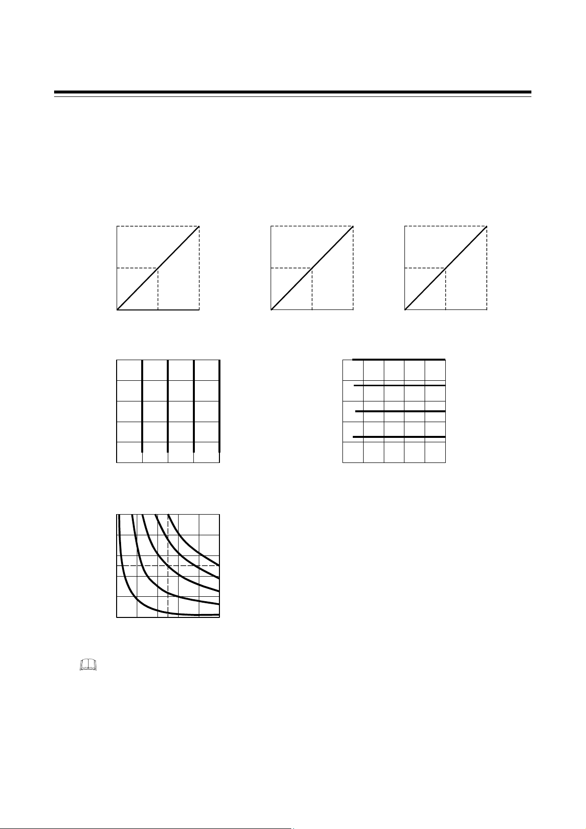
5. FUNCTIONS
A
A
A
A
5.7 Output Mode for Phase Control
When phase control is selected for a linearity load (resistance load), one of the following six output
types can be selected. The factory set value is proportional square voltage (electric power) to input.
(The output mode setting is invalid when the control method is zero-cross control.)
Proportional phase angle to input
100
Proportional voltage to input
100
Proportional square voltage
(electric power) to input
100
50
Phase angle ratio (%)
0
4 12 20
Input signal (mA)
Constant current control
100
8 mA12 mA16 mA 20 m
80
60
40
20
Output voltage (%)
0
25
0
50 75 100
Output current (%)
Constant power control
100
80
60
50
40
20
Output voltage (%)
0
20
0
40 50 60 80 100
Output current (%)
Input
signal
Input
signal
20 mA
16 mA
12 mA
8 mA
5 mA
50
Effective voltage (%)
0
41220
Input signal (mA)
100
80
60
40
20
Output voltage (%)
0
0
50
Electric power (%)
0
4 12 20
Input signal (mA)
Constant voltage control
20
40 60 80 100
Output current (%)
Input signal
20 m
16 m
12 m
8 mA
Constant current, Constant voltage and Constant power controls are optional.
IMR01V02-E1
53
Page 62

5. FUNCTIONS
(1) Constant current control
This is the function used to keep the output current constant in proportion to the input signal. This
function is effective when a heater with large resistance changes caused by temperature variations is
used (such as tantalum, superkanthal, tungsten, platinum, or molybdenum).
The maximum output current when the constant current control function is used coincides with the
rated current in the thyristor specification.
Operating condition Stability
Power supply voltage variation ±10 %
±2 % of full scale
Load variation 2 times
Caution for using constant current control function
If the rated current of thyristor differs from that maximum load current flowing through the heater,
compensate for the difference by setting the gradient. If there is the difference, a section where control
is disabled may come into existence. A compensation example when there is a difference between the
currents flowing through the thyristor and the heater is shown in the following.
Example: When used in the following condition
• Rated current of Thyristor: 30 A
• Maximum load current of heater: 15 A
• Input signal from controller: 4 to 20 mA DC
• Soft-start time setting: 0.0 seconds
The soft-start function is activated during four cycles from load operation start even at a
soft-start time of 0.0 seconds.
When used without setting the gradient, the maximum heater load current becomes 15 A at an input
signal of 12 mA. In this case, control is disabled if the input signal exceeds 12 mA.
Constant current control
100
54
Maximum load current (15 A) of heater
50
Current (%)
0
4 12 20
Input signal (mA)
Control is disabled within this section.
Continued on the next page.
IMR01V02-E1
Page 63

5. FUNCTIONS
Continued from the previous page.
In this case, set the gradient to 50 % so that the maximum heater load current will become 15 A at an
input signal of 20 mA. The gradient is valid even if internally set or set by the external gradient setter.
Constant current control
100
50
Current (%)
Gradient setting
50 %
0
4 12 20
Input signal (mA)
Maximum load c urrent (15 A) of heater
(2) Constant voltage control
This is a control method of compensating power supply voltage and load variations so that no output
voltage changes while in control.
Operating condition Stability
Power supply voltage variation ±10 %
±2 % of full scale
Load variation 2 times
(3) Constant power control
This is a control method of outputting the root mean square power value proportional to the input
signal even if there are power supply voltage and load variations while in control. This is suitable for
heater control such as by silicon carbide or silicon unit which increases its resistance value due to
temperature and secular changes.
Operating condition Stability
Power supply voltage variation ±10 %
±4 % of full scale
Load variation 2 times
The soft-start function is activated during four cycles from load operation start even at a
soft-start time of 0.0 seconds.
IMR01V02-E1
55
Page 64

5. FUNCTIONS
5.8 Current Limiter Function
This is the function of limiting a measured current value to a value not exceeding the preset current
limit value. A current value is measured for each constant cycle and then the maximum phase angle
not exceeding the current limit value is calculated from the above current value thus measured. If the
phase angle at that current output is larger than the maximum phase angle calculated, the current is
output at the maximum phase angle to restrict that current. The maximum phase angle is calculated
during a time period of 0.1 seconds from the start of load operation, and the current limit function is
activated after the maximum phase angle is calculated.
If a load through which large rush current flows is used, the current limit function
cannot restrict the above current. In this case, use the current limit function together
with the soft-start function.
Even at a soft-start time of 0.0 seconds, the soft-start function is activated in order to
calculate the maximum phase angle during a time period of 0.1 seconds from the start of load
operation.
If a current value exceeds “Current limit value + Differential gap (0.5 A or 1.0 A) *” due to
voltage variations or load resistance changes while the current limit function is being
activated, the maximum phase angle is immediately re-calculated to restrict it within a cycle
of 2.5 from the time when it exceeds “Current limit value + Differential gap.”
* Differential gap 0.5 A: 20 A, 30 A types
Differential gap 1 A: 45 A, 60 A, 80 A and 100 A types
If a current limit value is set to its maximum value, the current limit function is deactivated.
The current limiter function cannot be used when zero-cross control is selected.
5.9 Automatic Power Frequency Detection and Power Frequency Monitoring Function
Automatic power frequency detection
The instrument automatically detects a power supply frequency (50 Hz or 60 Hz) when the power is
turned on.
Detection range: 50 Hz: 45.0 to 54.9 Hz 60 Hz: 55.0 to 64.9 Hz
Action on occurrence of error: FREQ lamp is lit.
Thyristor output is turned off.
Power frequency monitoring function
This function monitors the power supply frequency and when it goes out of the detection range, the
error message display appears.
Detection range: 50 Hz: 45.0 to 54.9 Hz 60 Hz: 55.0 to 64.9 Hz
Action on occurrence of error: FREQ lamp is lit.
Thyristor output is turned off.
(The output can be turned ON when the error is canceled.)
56
IMR01V02-E1
Page 65

5. FUNCTIONS
5.10 Alarm Interlock Function
The alarm interlock function is used to hold the alarm state even if the power frequency or CT input
value is out of the alarm zone after its entry into the alarm zone once. Power frequency error (FREQ),
heater break alarm 1 (HBA1), thyristor breakdown alarm (THY. B) and heater break alarm 2 (HBA2)
can be interlocked.
Indication lamp: This lamp continues lighting until the alarm is released.
Alarm output: The alarm output continues being output until the alarm is released.
Alarm interlock release: The Alarm interlock can be released by the external contact signal.
5.11 Heater Break Alarm 1 (HBA1), Heater Break Alarm 2
(HBA2) and Thyristor Break-Down Alarm Functions
The heater break alarm (HBA) and thyristor break-down alarm monitors the current flowing through
the load by a dedicated current transformer (CT). The THW-3 compares the measured value with the
set values, and detects a fault in the heating circuit. In addition, there are several types of alarms
depending on control methods and applications of these alarms.
Read this chapter carefully to choose an suitable method and set an appropriate set value.
5.11.1 Number of alarm delay times
The alarm delay function is that which delays the occurrence of alarm in order to prevent alarm
malfunctioning. When an alarm condition becomes ON status, the output is suppressed until the preset
number of sampling times elapses. After the preset number of sampling times elapses, if the alarm
output is still ON status, the output will be produced. In addition, if the alarm state is released while
the alarm delay function is being activated, the alarm output is not turned on.
When the alarm types are the Heater break alarm 1 and Thyristor break-down alarm:
Alarm state > 5 sampling cycles * × Number of alarm delay times (1 to 99 times)
When the alarm is the heater break alarm 2:
Alarm state > 5 sampling cycles * × Number of alarm delay times (1 to 999 times)
* It is so designed that the alarm output is turned on when the alarm state corresponding to five
sampling times continues even with the number of alarm delay times not set.
Zero-cross control
HBA1 set value
CT input value
Alarm output
Capture
Alarm state
For the preset number of consecutive sampling cycles
ON OFF
IMR01V02-E1 57
Page 66

5. FUNCTIONS
5.11.2 Heater break alarm for phase control (Type 1)
Type 1 can be used as follows by using three heater break alarm set values.
(See Application 1 [P. 61].)
Heater break alarm 1 (HBA1) set value:
The alarm can be output when a heater break occurs by setting the heater break alarm set value.
Thyristor break-down set value:
It is possible to output an alarm when a thyristor element is shorted or broken by setting the thyristor
breakdown set value.
Heater break alarm 2 (HBA2) set value:
This alarm set value can be used as an auxiliary alarm.
For example, it can be used as a heater deterioration alarm if set to any value slightly smaller than
the heater break alarm set value to output the alarm before a heater break occurs when the load
current decreases due to heater deterioration, etc.
The heater break alarm of Type 1 cannot be used for heat generation substances such
as noble metals
In addition, it cannot be used for heat generation substances such as silicon carbide
making resistance changes with temperature variations and a lapse of time.
*
Noble metals (Such as platinum, molybdenum, tantalum, tungsten, or superkanthal)
Type 1 cannot be used for any load (such as lamp heater) whose resistance change due
to a change in temperature is large.
Type 1 cannot be used for any power supply waveforms other than a sine waveform.
(1) How alarm is activated
* making large resistance changes with temperature variations.
• When heater current does not flow (Heater break, malfunction of the control device, etc.)
When the phase angle is equal to or more than 15% and the current transformer (CT) input value
is equal to or less than the heater break alarm (HBA) set value for the preset number of
consecutive sampling cycles, an alarm status is produced. However, in order to prevent
malfunctioning, it is so designed that no heater break alarm occurs at an phase angle of less
than 15 % (less than 15 % of maximum load current).
• When heater current can not be turned off (Thyristor break-down or permanent damage)
When the current transformer (CT) input value is equal to or greater than the heater break alarm
*
set value
*
Thyristor break-down set value or Heater break alarm 2 (HBA2) set value
for the preset number of consecutive sampling cycles, an alarm status is produced.
The alarm will be turned off when the current transformer (CT) input value goes in and stays
at non-alarm range for five consecutive cycles.
(However, excepting a case where the alarm interlock function is used.)
58
IMR01V02-E1
Page 67

5. FUNCTIONS
(2) Setting the Heater break alarm
When using the heater break alarm, it is necessary to set the maximum load current set
value for alarm (MAXC). (See P. 37)
The following table shows the amount of current to be reduced when one heater is broken with heaters
parallel connected. It shows how much current is reduced when one heater is broken at the output
(phase angle) shown in the table. Set the heater break alarm set value by referring to the amount of
current reduced.
Delta connected
Break
Break
Break
(a) When heaters are not
parallel connected
(b) When two heaters are parallel
connected to each phase
(c) When three heaters are parallel
connected to each phase
Table 1: The amount of current reduced (Delta connected)
Number of parallel
connection of heater
When heaters are not parallel
connected
When two heaters are parallel
connected to each phase
When three heaters are parallel
connected to each phase
In order to prevent malfunctioning, it is so designed that no heater break alarm occurs at an phase angle of less than 15 %
(less than 15 % of maximum load current).
14 %
(180 °)
Reduction
of 6 %
Reduction
of 3 %
Reduction
of 2 %
29 %
(150 °)
Reduction
of 16 %
Reduction
of 7 %
Reduction
of 4 %
Output (Phase angle)
42 %
(120 °)
Reduction
of 26 %
Reduction
of 11 %
Reduction
of 7 %
57 %
(90 °)
Reduction
of 29 %
Reduction
of 13 %
Reduction
of 9 %
71 %
(60 °)
Reduction
of 31 %
Reduction
of 15 %
Reduction
of 10 %
86 %
(30 °)
Reduction
of 31 %
Reduction
of 16 %
Reduction
of 11 %
100 %
(0 °)
Reduction
of 28 %
Reduction
of 16 %
Reduction
of 11 %
Star connected (Y connected)
Break
Break
Break
(a) When heaters are not
parallel connected
IMR01V02-E1
(b) When two heaters are parallel
connected to each phase
(c) When three heaters are parallel
connected to each phase
Continued on the next page.
59
Page 68

5. FUNCTIONS
A
Continued from the previous page.
Table 2: The amount of current reduced (Star connected)
Number of parallel
connection of heater
When heaters are not parallel
connected
When two heaters are parallel
connected to each phase
When three heaters are parallel
connected to each phase
14 %
(180 °)
Reduction
of 8 %
Reduction
of 3 %
Reduction
of 2 %
29 %
(150 °)
Reduction
of 20 %
Reduction
of 8 %
Reduction
of 5 %
Output (Phase angle)
42 %
(120 °)
Reduction
of 32 %
Reduction
of 13 %
Reduction
of 8 %
57 %
(90 °)
Reduction
of 38 %
Reduction
of 16 %
Reduction
of 10 %
71 %
(60 °)
Reduction
of 43 %
Reduction
of 18 %
Reduction
of 11 %
86 %
(30 °)
Reduction
of 44 %
Reduction
of 19 %
Reduction
of 12 %
100 %
Reduction
of 42 %
Reduction
of 19 %
Reduction
of 12 %
In order to prevent malfunctioning, it is so designed that no heater break alarm occurs at an phase angle of less than 15 %
(less than 15 % of maximum load current).
Explanation of Table 1 and Table 2
(0 °)
Example: When heaters are not parallel connected with these heaters star-connected:
(See table 2.)
Heater break alarm 1 (HBA1) is set at 20 % before factory shipment. The heater break
alarm is turned on when the current reduces by more than 20 % from the computed heater
current value at each output (phase angle) as shown in Table 2.
In table 2, the current reduces by more than 20 % with one heater broken when the output
is larger than 29 % (phase angle: 150 °).
Current value (A)
Maximum
load current
value (A)
The current value
reduces by 20 %.
Heater break alarm ON
Computed heater current value
Heater break alarm 1 (HBA1) set value (20 %)
Current value (CT measured value) when one heater is broken
The heater break alarm is turned on as the computed heater current value reduces by 20 % at an output of 29 %
(phase angle: 150 °).
HBA alarm is turned on ≥ Computed heater current value − (Maximum load current set value (A) × HBA1 set value [20 %])
0
(210°)
Heater
break alarm
0 %
14 %
(180°)
OFF
29 %
(150°)
42 %
(120°)
57 %
(90°)
71 %
(60°)
ON
86 %
(30°)
60
Output (Phase angle)
100 %
(0°)
IMR01V02-E1
Page 69

Setting example of Heater break alarm
Application: Heater with the specification of a maximum load current of 100 A
Three-phase star connected
The heater is not connected in parallel.
The set value of heater break alarm 1 (HBA1) is used for heater break detection.
(The heater break alarm needs to be output at an output of more than 15 %.)
The set value of heater break alarm 2 (HBA2) is used for heater deterioration detection.
Set the related parameters as follows.
Parameter in Setting mode
Maximum load current set value for alarm (MAXC) *: 100 A
* Always set the maximum heater current value. (See P. 37)
Heater break alarm 1 set value setting (HBA1): 8 %
When the heater break alarm is detected at an output of more than 15 %, check for a value near an
output of 15 % by referring to Table 2. From Table 2, an output of 14 % (phase angle: 180 °) is very
close to an output of 15 %. Therefore, set 8 % corresponding to the amount of current reduced at an
output of 14 % (phase angle: 180 °) as the set value of heater break alarm 1 (HBA1).
Heater break alarm 2 set value setting (HBA2): 6 %
As the heater deterioration alarm must detect the degree of deterioration before the heater break
alarm occurs, set the set value of heater break alarm 2 (HBA2) to any value smaller than the set
value of heater break alarm 1 (HBA1). Here, the former is set at 6 % as an example.
Thyristor break-down set value setting (THb): 0 % [Thyristor break-down alarm unused]
Parameter in Engineering mode
The computed current value used for heater break alarm (HBA) determination point
The computed current value used for heater break alarm 1 (HBA1) determination point
= (Maximum load current set value) × (Heater break alarm 1 (HBA1) set value)
= 100 A × 8 % = 8 A Heater break alarm 1 (HBA1) current value 8 A
The computed current value used for heater break alarm 2 (HBA2) determination point
= (Maximum load current set value) × (Heater break alarm 2 (HBA2) set value)
= 100 A × 6 % = 6 A Heater break alarm 2 (HBA2) current value 6 A
The current value (8 Ampere) of heater break alarm 1 (HBA1) is set below the computed heater current
value. The current value (6 Ampere) of heater break alarm 2 (HBA2) is set above and below the
computed heater current value. (See the graph of next page.)
Alarm 1 output logic (LGA1): 1 [Heater break alarm 1 (ON at alarm output)]
Alarm 2 output logic (LGA2): 3 [Heater break alarm 2 (ON at alarm output)]
Number of heater break alarm 1 delay times (HbC1): 1 time
Heater break alarm 1 type (AS1): 0 [Type 1 (deviation alarm)]
Alarm interlock (ILS): 0 [Unused]
Number of heater break alarm 2 delay times (HbC2): 1 time
Heater break alarm 2 type (AS2): 0 [Type 1 (deviation alarm)]
Control method (ConT): 0 [Phase control]
Continued on the next page.
5. FUNCTIONS
IMR01V02-E1
61
Page 70

5. FUNCTIONS
A
Continued from the previous page.
Current value (A)
Maximum
load current
value (A)
Heater break alarm 2 (HBA2) set value (upper): 6 % (6 A)
Computed heater current value
Heater break alarm 2 (HBA2) set value (lower): 6 % (6 A)
Heater break alarm 1 (HBA1) set value: 8 % (8 A)
Current value (CT measured value)
when one heater is broken
When the output is less than 15 % the heater break alarm is not activated. Therefore, the
output of heater break alarm 1 (HBA1) is turned on if the computed heater current value
reduces by more than 8 % at an output of more than 15 %.
In addition, if the amount of computed heater current reduced is between 6 % and 8 % at
an output of more than 15 %, the output of heater break alarm 2 (HBA2) is turned on.
0
0 %
(210°)
14 %
(180°)
29 %
(150°)
42 %
(120°)
57 %
(90°)
71 %
(60°)
86 %
(30°)
Output (phase angle)
100 %
(0°)
The set value of heater break alarm 2 (HBA2) is set above and below the computed heater
current value (deviation high/low alarm).
The set value (above) of heater break alarm 2 (HBA2) is an alarm on the thyristor
break-down side.
This setting example shows the operation performed under the following ideal condition.
The actual operation differs depending on power supply voltage and load variations.
Therefore, set the value meeting the customer’s operating condition.
• Power supply voltage: Constant
• Load variation: None
• Balanced three-phase load
How alarm is checked
If an alarm occurs, the indication lamp (HBA1/HBA2) at the front lights.
In addition, the alarm signal is output from the alarm 1 or 2 of the input/output connector.
62
IMR01V02-E1
Page 71

5. FUNCTIONS
A
(3) Thyristor break-down alarm
The thyristor break-down alarm is turned on when the computed heater current value is larger than the
thyristor break-down set value set at each output (phase angle).
The thyristor break-down alarm is turned on when the computed heater current value is larger than the thyristor break-down set value set at each output
(phase angle).
Thyristor break-down alarm is turned on ≥ Computed heater current value + (Maximum load current set value (A) × Thyristor break-down set value [20 %])
Current value (A)
Thyristor break-down set value: 20 % (Factory set value)
Maximum
load current
value (A)
0
0 %
(210°)
14 %
(180°)
29 %
(150°)
42 %
(120°)
57 %
(90°)
71 %
(60°)
86 %
(30°)
Computed heater current value
Output (phase angle)
100 %
(0°)
When using the thyristor break-down alarm, it is also necessary to set the maximum
load current set value for alarm (MAXC). (See P. 37)
Conduct the setting by referring to Setting example of Heater break alarm (P. 61).
How alarm is checked
If an alarm occurs, the indication lamp (THY.B) at the front lights.
In addition, the alarm signal is output from the alarm 1 or 2 of the input/output connector.
IMR01V02-E1
63
Page 72

5. FUNCTIONS
5.11.3 Heater break alarm for phase control (Type 2)
Type 2 corresponds to a heater break alarm when one heater is used. (See Application)
Use the heater break alarm of Type 2 when a noble metal heater with large resistance changes caused
by temperature variations is used.
How alarm is activated
Application (When heater break alarm 1 is used for heater break detection
No type 2 can be used when two or more heaters are used in parallel connection.
• When heater current does not flow (Heater break, malfunction of the control device, etc.)
When the phase angle is equal to or more than 15 % and the current transformer (CT) input value
is equal to or less than the heater break alarm (HBA) set value for the preset number of
consecutive sampling cycles, an alarm status is produced.
However, in order to prevent malfunctioning, it is so designed that no heater break alarm
occurs at an phase angle of less than 15 % (less than 15 % of maximum load current).
• When heater current can not be turned off (Thyristor break-down or permanent damage)
When the current transformer (CT) input value is equal to or greater than the thyristor break
down set value for the preset number of consecutive sampling cycles, an alarm status is
produced.
The alarm will be turned off when the current transformer (CT) input value goes in and stays
at non-alarm range for five consecutive cycles.
(However, excepting a case where the alarm interlock function is used.)
and the thyristor break-down alarm, for thyristor element
shorting detection)
For Type 2, no set value of heater break alarm 2 (HBA2) is used. Setting the parameter as shown in
the following performs the operation as illustrated in the Figure (P. 65).
Set the heater break alarm 1 set value and thyristor break-down set value to approximately
5 % of the maximum load current value. Do not set the heater break alarm set value to
more than 15 %.
Parameter in Setting mode
Maximum load current set value for alarm (MAXC)
1
: 20.0 A
Heater break alarm 1 set value setting (HBA1): 5 %
Thyristor break-down set value setting (THb): 5 %
Heater break alarm 2 set value setting (HBA2)
1
Always set the maximum heater current value. (See P. 37)
2
Always set the heater break alarm 2 to “0: Heater break alarm 2 unused.”
2
: 0 (Heater break alarm 2 unused)
The computed current value used for heater break alarm (HBA) and thyristor break-down alarm
determination points
The computed current value used for heater break alarm 1 (HBA1) determination point
= (Maximum load current set value) × (Heater break alarm 1 (HBA1) set value)
= 20.0 A × 5 % = 1.0 A Heater break alarm 1 (HBA1) current value 1.0 A
The computed current value used for thyristor break-down alarm determination point
= (Maximum load current set value) × (Thyristor break-down set value)
= 20.0 A × 5 % = 1.0 A Thyristor break-down current value 1.0 A
Continued on the next page.
64
IMR01V02-E1
Page 73

r
A
r
r
Continued from the previous page.
Parameter in Engineering mode
Alarm 1 output logic (LGA1): 1 [Heater break alarm 1 (ON at alarm output)]
Alarm 2 output logic (LGA2): 2 [Thyristor break-down alarm (ON at alarm output)]
Number of heater break alarm 1 delay times (HbC1): 1 time
Heater break alarm 1 type (AS1): 1 [Type 2 (Absolute value alarm)]
Alarm interlock (ILS): 0 [Unused]
Number of heater break alarm 2 delay times (HbC2): This parameter does not use.
Heater break alarm 2 type (AS2): This parameter does not use.
Control method (ConT): 0 [Phase control]
(When the maximum load current value is set to 20 A)
Current (A)
5. FUNCTIONS
Alarm range of heater break alarm
(Thyristor break-down)
When the phase angle is 0 % and the
current transformer input value is equal
to or greater than the thyristo
break-down set value for the preset
number of consecutive sampling cycles,
an alarm status is produced.
Heater break alarm 1 set value 5 % (1.0 A)
14.9 %
No heater break alarm occurs if within this range.
However, the alarm occurs in the case of thyristor break-down.
100 % 0
larm range of heater break alarm
When the phase angle is equal to o
more than 15% and the current
transformer input value is equal to or less
than the heater break alarm set value fo
the preset number of consecutive
sampling cycles, an alarm status is
produced.
Phase angle (%)
How alarm is checked
If an alarm occurs, the indication lamp (HBA1, THY.B) at the front lights.
In addition, the alarm signal is output from the alarm 1 or 2 of the input/output connector.
5.11.4 Heater break alarm for zero-cross control
The following usage is available in zero-cross control. (See Application)
Heater break alarm 1 (HBA1) set value:
The alarm can be output when a heater break occurs by setting the heater break alarm set value.
Thyristor break-down set value:
It is possible to output an alarm when a thyristor element is shorted or broken by setting the thyristor
break-down set value.
Heater break alarm 2 (HBA2) set value:
The heater break alarm 2 (HBA2) set value does not use when in the zero-cross control.
Set the set value of Heater break alarm 2 to “0: Heater break alarm 2 unused.”
IMR01V02-E1
65
Page 74

5. FUNCTIONS
How alarm is activated
• When heater current does not flow (Heater break, malfunction of the control device, etc.)
When the control output is ON and the current transformer (CT) input value is equal to or less
than the heater break alarm 1 (HBA1) set value for the preset number of consecutive sampling
cycles, an alarm status is produced.
• When heater current can not be turned off (Thyristor break-down or permanent damage)
When the control output is OFF and the current transformer (CT) input value is equal to or
greater than the thyristor break-down set value for the preset number of consecutive sampling
cycles, an alarm status is produced.
The alarm will be turned off when the current transformer (CT) input value goes in and stays
at non-alarm range for five consecutive cycles.
(However, excepting a case where the alarm interlock function is used.)
Application (When heater break alarm 1 is used for heater break detection
and the thyristor break-down alarm, for thyristor element
shorting detection)
Parameter in Setting mode
1
Maximum load current set value for alarm (MAXC)
: 20.0 A
Heater break alarm 1 set value setting (HBA1): 80 %
Thyristor break-down set value setting (THb): 30 %
Heater break alarm 2 set value setting (HBA2)
1
Always set the maximum heater current value. (See P. 37)
2
Always set the heater break alarm 2 to “0: Heater break alarm 2 unused.”
2
: 0 (Heater break alarm 2 unused)
The computed current value used for heater break alarm (HBA) and thyristor break-down alarm
determination points
The computed current value used for heater break alarm 1 (HBA1) determination point
= (Maximum load current set value) × (Heater break alarm 1 set value)
= 20.0 A × 80 % = 16.0 A Heater break alarm 1 (HBA1) current value 16.0 A
The computed current value used for thyristor break-down alarm determination point
= (Maximum load current set value) × (Thyristor break-down set value)
= 20.0 A × 30 % = 6.0 A Thyristor break-down current value 6.0 A
Parameter in Engineering mode
Alarm 1 output logic (LGA1): 1 [Heater break alarm 1 (ON at alarm output)]
Alarm 2 output logic (LGA2): 2 [Thyristor break-down alarm (ON at alarm output)]
Number of heater break alarm 1 delay times (HbC1): 1 time
Heater break alarm 1 type (AS1): This parameter does not use.
Alarm interlock (ILS): 0 [Unused]
Number of heater break alarm 2 delay times (HbC2): This parameter does not use.
Heater break alarm 2 type (AS2): This parameter does not use.
Control method (ConT): 1 [Zero-cross control]
66
IMR01V02-E1
Page 75

5. FUNCTIONS
20.0 A
HBA1 set value 80 % (16.0 A)
CT input value
Capture
Alarm output
18.5 A
15.5 A
For the preset number of consecutive sampling cycles
15.5 A 15.5 A 15.5 A 15.5 A 15.5 A
ON OFF
Heater break alarm
20.0 A 20.0 A 20.0 A
Thyristor break-down set value
30 % (6.0 A)
CT input value
Alarm output
Capture
For the preset number of consecutive sampling cycles
ON OFF
Thyristor break-down alarm
How alarm is checked
If an alarm occurs, the indication lamp (HBA1, THY.B) at the front lights.
In addition, the alarm signal is output from the alarm 1 or 2 of the input/output connector.
IMR01V02-E1
67
Page 76

5. FUNCTIONS
5.12 FAIL Alarm
An alarm occurs if a board error of this instrument is detected by the self-diagnostic function.
Action taken when an alarm occurs: The FAIL lamp lights.
Thyristor output is turned off.
5.13 Negative Phase Sequence Alarm
It is fudged whether or not each phase is in positive phase sequence when power is turned on, and an
alarm occurs if wiring is made by mistaking phase sequence.
In addition, an alarm occurs also when only two phases are wired.
Action taken when an alarm occurs: The PHASE lamp lights.
Thyristor output is turned off.
5.14 Over Current Alarm (optional)
An alarm occurs when the current exceeding 1.2 times the rating flows through this instrument.
Action taken when an alarm occurs: The OCR lamp lights.
Thyristor output is turned off.
5.15 Fuse Break Alarm (optional)
An alarm occurs when the fast-blow fuse in this instrument blew.
Action taken when an alarm occurs: The FUSE lamp lights.
Thyristor output is turned off.
Fuse break alarm is not available when the fast-blow fuse (with microswitch) is not
provided.
5.16 Set Data Lock Function
The set lock level restricts parameter setting changes by key operation. This function prevents the
operator from making errors during operation. The setting of data lock is made for each mode.
×: Mode unlock (Settable) −: Mode lock (Unsettable)
Set value Engineering mode Setting mode
68
0000
0001
0010
0011
− ×
− −
× ×
× −
The numeric value can be checked in Setting mode even if locked.
The Engineering mode cannot be called up if locked.
IMR01V02-E1
Page 77

5. FUNCTIONS
5.17 External Contact Input (DI) Function
The following operation is performed by the external contact signal. The external contact state can be
checked by the contact input state monitor.
(1) Auto/Manual mode transfer
Use to select the Auto/Manual mode by the external contact input.
When the external contact is open: Auto mode
When the external contact is closed: Manual mode
How auto set value or manual set value is checked
These values can be checked on the Input signal monitor 1 and Input signal monitor 2 (only auto set
value).
External contact action selection
Auto/Manual mode transfer can select the operating item. The action type can be selected on the
Contact input action (dISL). (P. 43).
(2) RUN/STOP transfer
The RUN/STOP can be selected by the external contact signal.
When the external contact is open: STOP
When the external contact is closed: RUN
If the RUN/STOP transfer function is used, set the RUN/STOP action (rSA) to “1: Use.”
(See P. 46)
(3) Alarm interlock release
The alarm interlock is released by the external contact signal.
When the external contact is closed: Alarm interlock release
No alarm interlock can be released when in the alarm state. Release the alarm interlock after
the cause of the alarm is cleared up.
IMR01V02-E1
69
Page 78

6. MAINTENANCE
In order to prevent electric shock or instrument failure, always conduct
necessary work after power supplied to the entire system is turned off.
Conduct work after this instrument is cooled. As the temperature of this
instrument is very high just after the power is turned off, never touch the
instrument while heated.
WARNING
!
6.1 Daily Inspection
In order to prevent accident and instrument failure, inspect the instrument periodically.
Check item Details
Inspecting main
circuit terminal
tightening torque
Cleaning of thyristor
As the large current flows through each hexagon headed bolt used for the
main circuit terminal, the loosened bolt may generate heat to cause ignition.
Inspect the tightening torque of the bolt periodically. If loosened, tighten it
with adequate torque.
Recommended tightening torque:
1.6 N⋅m (20 A, 30 A)
3.8 N⋅m (45 A, 60 A)
9.0 N⋅m (80 A, 100 A)
For the torque wrench, see page 13.
The attachment of dust to the heat radiation fins may worsen the cooling
effect. Therefore, remove the dust attached using a cleaner.
70 IMR01V02-E1
Page 79

6. MAINTENANCE
6.2 Troubleshooting
General causes to be assumed and measures to be taken when an error occurs in this instrument are
described in the following. For any inquiries, please contact RKC sales office or the agent, to confirm
the specifications of the product.
Problem Probable cause Solution
The FAIL lamp lights Error of board inside this instrument
The FREQ lamp lights
Not to be output
No gradient is set
There is no automatic setting input
The fast-blow fuse is broken. Replace the fast-blow fuse.
The FUSE lamp lights The fast-blow fuse is broken. Replace the fast-blow fuse.
The PHASE lamp lights
No output is turned off.
A thyristor element is shorted.
The HBA1 lamp lights A heater is broken. Turn off the power, and check or replace
The HBA2 lamp lights the heater, etc.
The THY.B lamp lights No soft-start time is appropriately set.
A thyristor element is damaged.
The OCR lamp lights
Power frequency is out of the allowable
range (detection range) when power
is turned on or during operation.
The power supply voltage is not being
supplied
Wiring is conducted by mistaking phase
sequence
The three-phase power supply is not
supplied
The automatic set value is set to the
maximum value.
A current of more than 1.2 times the
rating of this instrument flowed.
Turn off the power once. If a lamp lights
after the power is turned on again, please
contact RKC sales office or the agent.
Check the value of power supply
frequency, and turn off the power once.
If a lamp lights after the power is turned
on again, please contact RKC sales
office or the agent.
Supply the power.
Set the external gradient or internal
gradient.
Check whether or not wiring is conducted
by mistaking the output signal of the
controller and the type of thyristor input
signal.
Check that the temperature controller
normally operates.
Conduct wiring so that the phase of each
power supply terminal (R, S or T) coincides
with that of each main circuit terminal
(1/L1, 3/L2 or 5/L3).
Supply the three-phase power.
Check the output signal of temperature
controller.
Please contact RKC sales office or the
agent.
If a load generating large rush current is
used, thyristor break-down may occur
when no soft-start time is appropriately
set. In such a case, make the soft-start
time longer.
For any causes other than the above,
turn the power off and then contact to
your nearest RKC sales agent or our
sales office.
Turn off the power, and check or replace
the heater, etc.
IMR01V02-E1 71
Page 80

6. MAINTENANCE
6.3 Replacement of the Fast-Blow Fuse
CAUTION
Use a torque wrench for removing or tightening each hexagon headed bolt which fixes
the fuse. Always remove or tighten the bolt by contacting the diagonal surfaces of the
wrench with those of the bolt head.
Recommended tool:
- Torque wrench and Socket: Manufactured by TOHNICHI MFG. CO., LTD
- Extension: Manufactured by KTC (KYOTO TOOL)
Model code of adjustable type torque
wrench with ratchet head
20 A and 30 A QL6N M6
45 A to 100 A QL25N M10
Socket size
Model code of the extension
20 A to 100 A BE10-50
6.3.1 Replacement of the fast-blow fuse (without microswitch)
1. Loosen two screws which fix the cover using a Phillips head screwdriver.
Fixed screws
72
IMR01V02-E1
Page 81

2. Slide the cover upward.
3. Slant the top of the cover and then pull out the cover.
6. MAINTENANCE
Cover
Cover
Cover guide
Main body guide
4. Remove two hexagon headed bolts which fix the fast-blow fuse using a torque wrench and then
remove the blown fast-blow fuse.
Fast-blow fuse Hexagon headed bolts
Hexagon headed bolts size
20 A and 30 A: M6
45 A to 100 A: M10
IMR01V02-E1
73
Page 82

6. MAINTENANCE
5. Replace the blown fast-blow fuse with a new one. First temporarily tighten these two hexagon
headed bolts to fix the fast-blow fuse and then tighten them at specified torque using the torque
wrench.
Always temporarily tighten the two hexagon headed bolts first.
Recommended tightening torque
20 A and 30 A
45 A to 100 A
5.0 N⋅m (50.98 kgf⋅cm)
23.5 N⋅m (239.63 kgf⋅cm)
6. Match the cover guide with the rear of the main body guide, and close the cover.
Cover guide
Main body guide
7. Tighten the two screws which fix the cover using the Phillips head screwdriver to finish the work.
74
IMR01V02-E1
Page 83

6. MAINTENANCE
6.3.2 Replacement of the fast-blow fuse (with microswitch)
1. Remove the front cover according to the same way as replacing the fast-blow fuse (without
microswitch).
2. Disconnect the connector which connects the fast-blow fuse to the main body.
Fast-blow fuse (with microswitch)
Microswitch
Disconnect the connector
Enlarged view
3. Remove two hexagon headed bolts which fix the fast-blow fuse using a torque wrench and then
remove the blown fast-blow fuse.
Hexagon headed bolts
Hexagon headed bolts size
20 A and 30 A: M6
45 A to 100 A: M10
4. Replace the blown fast-blow fuse with a new one. First temporarily tighten these two hexagon
headed bolts to fix the fast-blow fuse and then tighten them at specified torque using the torque
wrench.
Always temporarily tighten the two hexagon headed bolts first.
Recommended tightening torque
20 A and 30 A
45 A to 100 A
IMR01V02-E1
5.0 N⋅m (50.98 kgf⋅cm)
23.5 N⋅m (239.63 kgf⋅cm)
75
Page 84

6. MAINTENANCE
5. Connect the connector which connects the fast-blow fuse to the main body.
Fast-blow fuse (with microswitch)
Microswitch
Connect the connecter.
Enlarged view
6. Close the front cover to finish the work. Close the front cover according to the same way as
fixing the fast-blow fuse (without microswitch).
76
IMR01V02-E1
Page 85

7. SPECIFICATIONS
Number of phase: Three-phase
Rated current: 20 A AC, 30 A AC, 45 A AC, 60 A AC, 80 A AC and 100 A AC
(The rated current drops when the ambient temperature exceeds 40 °C.)
Minimum load current: 1 A
Power supply voltage: Main circuit: 360 to 484 V AC [Including power supply voltage variation]
(Rating: 400 to 440 V AC)
Control circuit: 180 to 264 V AC [Including power supply voltage variation]
(Rating: 200 to 240 V AC)
Power frequency: 50/60 Hz (Automatic discriminating)
Allowable power frequency variations:
Performance guarantee: 50 Hz ±1 Hz, 60 Hz ± 1 Hz
Operation guarantee: 45.0 to 54.9 Hz (50 Hz)
55.0 to 64.9 Hz (60 Hz)
Output voltage range: 0 to 98 % of rated voltage
Applicable load: Phase control: Linearity load (resistor load)
Control of primary side of a transformer
Recommended magnetic field density:
Approx. 0.8 tesla (8, 000 gauss) or less
Zero-cross control: Linearity load (resistor load)
Output mode: Proportional phase angle to input
Proportional voltage to input
Proportional square voltage (electric power) to input
Constant current control (optional)
Constant voltage control (optional)
Constant power control (optional)
The output mode is valid only when the linearity load (resistor load)
is used in the phase control.
Control method: Phase control
Zero-cross control
Input signal: Hardware 1: Current input: 0 to 20 mA DC, 4 to 20 mA DC
Voltage input: 0 to 5 V DC, 1 to 5 V DC
Voltage pulse input: 0/12 V DC
Dry contact input
Hardware 2: Voltage input: 0 to 10 V DC
Voltage pulse input: 0/12 V DC, 0/24 V DC
Dry contact input
(Specify either one of them when ordering. However, it is
possible to change if it is the input signal within the same
hardware.)
IMR01V02-E1 77
Page 86

7. SPECIFICATIONS
Input impedance: Current input 0 to 20 mA DC: 100 Ω
Current input 4 to 20 mA DC: 100 Ω
Voltage input 0 to 5 V DC: 30 kΩ
Voltage input 1 to 5 V DC: 30 kΩ
Voltage input 0 to 10 V DC: 68 kΩ
Voltage pulse input 0/12 V DC: 30 kΩ (Hardware 1), 68 kΩ (Hardware 2)
Voltage pulse input 0/24 V DC: 68 kΩ
Dry contact input: 47 kΩ
Action at input break: Current input: Downscale (control output OFF)
Voltage input: Downscale (control output OFF)
Voltage pulse input: Downscale (control output OFF)
Allowable input voltage: Current input: Equivalent to 0 to 2.2 V
Voltage input: 0 to 19 V (0 to 5 V DC, 1 to 5 V DC)
0 to 30 V (0 to 10 V DC)
Voltage pulse input: Hardware 1: 0 to 19 V (0/12 V DC)
Hardware 2: 0 to 30 V (0/12 V DC, 0/24 V DC)
External contact input (DI):
Number of input point: 3 points
Input method: Dry contact input
Dry contact: Open state: 500 kΩ or more
Closed state: 10 Ω or less
Contact current: 10 mA or less
Voltage when opened: Approx. 5 V DC
Function: Auto/Manual mode transfer
Open state: Auto mode
Closed state: Manual mode
RUN/STOP transfer
Open state: STOP
Closed state: RUN
Alarm interlock release
Closed state: Alarm interlock release
Current transformer (CT) input (optional):
Number of input point: 2 or 3 points
Input range: 0.0 to 100.0 A
Sampling cycle: 20 ms (50 Hz), 16.6 ms (60 Hz)
Potential Transformer (PT) input (optional):
Number of input point: 3 points
Input range: 0.0 to 510.0 V
Sampling cycle: 20 ms (50 Hz), 16.6 ms (60 Hz)
78
IMR01V02-E1
Page 87

External manual set value: 0 to 100 %
Set by the setter (optional)
Internal manual set value: 0.0 to 100.0 %
Set by the THW-3 front keys
External gradient set value: 0 to 100 %
Set by the setter (optional)
Internal gradient set value: 0.00 to 1.00 (0 to 100 %)
Set by the THW-3 front keys
Output limiter (high) set value: 0.0 to 100.0 %
Set by the THW-3 front keys
Output limiter (high) at the time of start:
0.0 to 100.0 %
Set by the THW-3 front keys
Output limiter (high) time at the time of start:
0.0 to 600.0 seconds
Set by the THW-3 front keys
Output limiter (low) set value: 0.0 to 100.0 %
Set by the THW-3 front keys
Base-up set value: 0.0 to 100.0 %
Set by the THW-3 front keys
Ramp (Soft-start/Soft-down) function:
0.0 to 99.9 seconds
Set by the THW-3 front keys
Current limiter function (optional):
20 A: 0.0 to 22.0 A
30 A: 0.0 to 33.0 A
45 A: 0 to 50 A
60 A: 0 to 66 A
80 A: 0 to 88 A
100 A: 0 to 110 A
Set by the THW-3 front keys
If a current limit value is set to its maximum value, the
current limit function is deactivated.
7. SPECIFICATIONS
IMR01V02-E1
79
Page 88

7. SPECIFICATIONS
Alarm function: Number of input point: 2 points
Output type: Open collector output
24 V DC, maximum 100 mA
Alarm type: Power frequency error
Negative phase sequence alarm
Heater break alarm 1 (optional)
Thyristor break-down alarm (optional)
Heater break alarm 2 (optional)
Over current alarm (optional)
Fuse break (optional)
Self-diagnostic function: Check item: Board error
EEPROM error
Calibration data error
Range check of set value
Error displays: The FAIL lamp lights
Ambient temperature: 0 to 40 °C (Performance guarantee range)
−15 to +55 °C (Operation guarantee range)
Ambient humidity: 5 to 95 %RH (Non-condensing)
Power consumption: 21 VA
Withstand voltage: Between main circuit and grounding terminals: 1 minute at 2000 V AC
Insulation resistance: Between main circuit and grounding terminals: 20 MΩ or more as 500 V DC
Cooling method: Natural convection
Mounting method: Vertical mounting
Dimensions: See 2.3 Dimensions (P. 8).
(Absolute humidity: MAX.W.C 29 g/m
3
dry air at 101.3 kPa)
Weight: Approx. 10.3 kg (20 to 60 A types)
Approx. 13.6 kg (80 and 100 A types)
Step-down transformer: Power frequency: 50/60 Hz
Primary side (input) voltage: 440 V
Secondary side (output) voltage: 220 V
Withstand voltage: Primary side and secondary side terminals:
1 minute at 2500 V AC
Insulation resistance: 500 V DC, 100 MΩ
80
IMR01V02-E1
Page 89
APPENDIX
How to fix the terminal cover (optional)
In order to prevent electric shock or instrument failure, always fix or remove the
terminal cover after power supplied to the entire system is turned off.
(1) Checking the product
If there is any shortage of accessories, contact the RKC sales office or your nearest RKC sales agent.
• Spacer……4 • Screw……4 • Terminal cover……2
(2) Mounting procedures
WARNING
!
Tools necessary for mounting: Flat blade screwdriver and Phillips screwdriver
Install each spacer using a flat blade screwdriver. In this case, always tighten it with the
screwdriver inserted into the slit at its top.
(Recommended tightening torque: 0.88 N・m [8.9 kgf⋅cm])
If tightened using a spanner, the insulating coating formed along the spacer may be
Place the terminal cover at its mounting location.
separated. If the insulating coating was separated, poor insulation may result.
Tighten each screw using the Phillips head screwdriver to fix the terminal cover.
(Recommended tightening torque: 1.08 N・m [11.0 kgf⋅cm])
3
Expanded view of
the top of the spacer
Slit
Terminal cover
Screw
Terminal cover
Spacer
2
1
Mounting holes
IMR01V02-E1 81
Page 90

APPENDIX
Description of terms
Following table is descriptions of term used in this manual.
Term Description
Maximum load current (value) The maximum load current value means a current value which flows through
the heater at an output of 100 % (phase angle: 0°).
Auto mode This is to automatically adjust power (output value) by the input signal from the
Manual mode
(External/Internal)
Input signal In this manual, the following three items are called input signals.
Gradient setting
(External/Internal)
RUN The operation of this instrument is started.
STOP The operation of this instrument is stopped.
HBA This is the Heater Break Alarm.
CT Current Transformer
PT Potential Transformer
controller.
Input signal type: 0 to 20 mA DC, 4 to 20 mA DC, 0 to 5 V DC,
1 to 5 V DC, 0 to 10 V DC, 0/12 V DC, 0/24 V DC
External manual mode:
This is to manually adjust power (output value) by manipulating the external
setter (potentiometer).
Internal manual mode:
This is to manually adjust power (output value) by manipulating the front keys.
• Auto set value (value of Auto mode) • Internal manual set value
• External manual set value
External gradient setting:
This is to set the gradient value by the external setter (potentiometer).
Internal gradient setting:
This is to set the gradient value by the front keys.
HBA1: Heater Break Alarm 1
HBA2: Heater Break Alarm 2
Character symbols
0 1 2 3 4 5 6 7 8 9
D
(d)
Degree
QR
(q) (r)
/
B
A C E F G H I J K L
(b)
N O
M P S T U u V W
(n) (o)
X Y Z
Lighting state of the character LED
: Dim lighting : Bright lighting : Flashing
Minus Period
82
IMR01V02-E1
Page 91

The first edition: NOV. 2005 [IMQ00]
Page 92

RKC INSTRUMENT INC.
HEADQUARTERS: 16-6, KUGAHARA 5-CHOME, OHTA-KU TOKYO 146-8515 JAPAN
PHONE: 03-3751-9799 (+81 3 3751 9799)
E-mail: info@rkcinst.co.jp
FAX: 03-3751-8585 (+81 3 3751 8585)
IMR01V02-E1 NOV. 2005
 Loading...