


 Loading...
Multi-point Digital Controller
MA900/MA901
Initial Setting Manual
|
|
|
|
|
|
|
|
® RKC INSTRUMENT INC. |
IMR01H03-E4 |
|
|
|
|
|
|
|
|
||
|
|
||||||||
|
|
||||||||
|
|
|
|
|
|
|
|
||
|
|
|
|
|
|
|
|
||
|
|

!"Modbus is a registered trademark of Schneider Electric.
!"Company names and product names used in this manual are the trademarks or registered trademarks of the respective companies.
All Rights Reserved, Copyright 2001, RKC INSTRUMENT INC.
Thank you for purchasing this RKC instrument. In order to achieve maximum performance and ensure proper operation of your new instrument, carefully read all the instructions in this manual. Please place this manual in a convenient location for easy reference.
|
|
SYMBOLS |
|
|
: This mark indicates precautions that must be taken if there is danger of electric |
|
WARNING |
|
|
|
shock, fire, etc., which could result in loss of life or injury. |
|
|
: This mark indicates that if these precautions and operating procedures are not |
|
CAUTION |
|
|
|
taken, damage to the instrument may result. |
|
|
!: This mark indicates that all precautions should be taken for safe usage.
: This mark indicates important information on installation, handling and operating procedures.
:This mark indicates supplemental information on installation, handling and operating procedures.
: This mark indicates where additional information may be located.
!WARNING
!"An external protection device must be installed if failure of this instrument could result in damage to the instrument, equipment or injury to personnel.
!"All wiring must be completed before power is turned on to prevent electric shock, fire or damage to instrument and equipment.
!"This instrument must be used in accordance with the specifications to prevent fire or damage to instrument and equipment.
!"This instrument is not intended for use in locations subject to flammable or explosive gases.
!"Do not touch high-voltage connections such as power supply terminals, etc. to avoid electric shock.
!"RKC is not responsible if this instrument is repaired, modified or disassembled by other than factory-approved personnel. Malfunction can occur and warranty is void under these conditions.
IMR01H03-E4 |
i-1 |


 CAUTION

!This is a Class A instrument. In a domestic environment, this instrument may cause radio interference, in which case the user may be required to take adequate measures.
!This instrument is protected from electric shock by reinforced insulation. Provide reinforced insulation between the wire for the input signal and the wires for instrument power supply, source of power and loads.
!Be sure to provide an appropriate surge control circuit respectively for the following:
-If input/output or signal lines within the building are longer than 30 meters.
-If input/output or signal lines leave the building, regardless the length.
!This instrument is designed for installation in an enclosed instrumentation panel. All highvoltage connections such as power supply terminals must be enclosed in the instrumentation panel to avoid electric shock by operating personnel.
!All precautions described in this manual should be taken to avoid damage to the instrument or equipment.
!All wiring must be in accordance with local codes and regulations.
!All wiring must be completed before power is turned on to prevent electric shock, instrument failure, or incorrect action.
The power must be turned off before repairing work for input break and output failure including replacement of sensor, contactor or SSR, and all wiring must be completed before power is turned on again.
!To prevent instrument damage or failure, protect the power line and the input/output lines from high currents with a protection device such as fuse, circuit breaker, etc.
!Prevent metal fragments or lead wire scraps from falling inside instrument case to avoid electric shock, fire or malfunction.
!Tighten each terminal screw to the specified torque found in the manual to avoid electric shock, fire or malfunction.
!For proper operation of this instrument, provide adequate ventilation for heat dispensation.
!Do not connect wires to unused terminals as this will interfere with proper operation of the instrument.
!Turn off the power supply before cleaning the instrument.
!Do not use a volatile solvent such as paint thinner to clean the instrument. Deformation or discoloration will occur. Use a soft, dry cloth to remove stains from the instrument.
!To avoid damage to instrument display, do not rub with an abrasive material or push front panel with a hard object.
!Do not connect modular connectors to telephone line.
NOTICE
!This manual is written for RKC service engineers or qualified technicians. This manual is also prepared especially for readers who already have a fundamental knowledge of electricity, control, computer and communication.
!The figures, diagrams and numeric values used in this manual are only for purpose of illustration.
!RKC is not responsible for any damage or injury that is caused as a result of using this instrument, instrument failure or indirect damage.
!Periodic maintenance is required for safe and proper operation of this instrument. Some components have a limited service life, or characteristics that change over time.
!Every effort has been made to ensure accuracy of all information contained herein. RKC makes no warranty expressed or implied, with respect to the accuracy of the information. The information in this manual is subject to change without prior notice.
!No portion of this document may be reprinted, modified, copied, transmitted, digitized, stored, processed or retrieved through any mechanical, electronic, optical or other means without prior written approval from RKC.
i-2 |
IMR01H03-E4 |

CONTENTS
|
|
|
Page |
1. PROCEDURE FOR INITIALIZATION.................................... |
1 |
||
1.1 |
Transfer to Engineering Mode ......................................................................... |
2 |
|
1.2 |
Procedure for Parameter Setting ..................................................................... |
4 |
|
1.3 |
End of Engineering Mode ................................................................................ |
9 |
|
2. DETAILS OF PARAMETER SETTING ............................... |
10 |
||
2.1 |
Attention Items in Setting............................................................................... |
12 |
|
2.2 |
F10 |
Display function ...................................................................................... |
17 |
2.3 |
F21 |
Input Specification .................................................................................. |
18 |
2.4 |
F22 |
Current Transformer (CT) Input Specification ........................................ |
20 |
2.5 |
F24 |
Contact Input Specification..................................................................... |
22 |
2.6 |
F31 |
Output Function...................................................................................... |
24 |
2.7 |
F32 |
Alarm Output Function............................................................................ |
26 |
2.8 |
F41 |
Alarm 1 Function/F42 Alarm 2 Function/F43 Alarm 3 Function.............. |
27 |
2.9 |
F51 |
Control Action ......................................................................................... |
29 |
2.10 F61 Communication Function...................................................................... |
30 |
||
2.11 F91 Displayed for Maintenance Information ................................................ |
31 |
||
3. INITIALIZE COMMUNICATION DATA................................ |
32 |
||
3.1 |
RKC Communication Protocol ....................................................................... |
32 |
|
3.2 |
Modbus Communication Protocol.................................................................. |
42 |
|
3.2.1 Communication data list ................................................................................... |
42 |
||
3.2.2 Data map.......................................................................................................... |
49 |
||
4. INPUT RANGE TABLES..................................................... |
55 |
||
IMR01H03-E4 |
i-3 |
MEMO
i-4 |
IMR01H03-E4 |
1. PROCEDURE FOR INITIALIZATION
Initialization is to set parameters relating to instrument specifications (input type, input range, alarm type, etc.). Engineering mode that can do this setting.
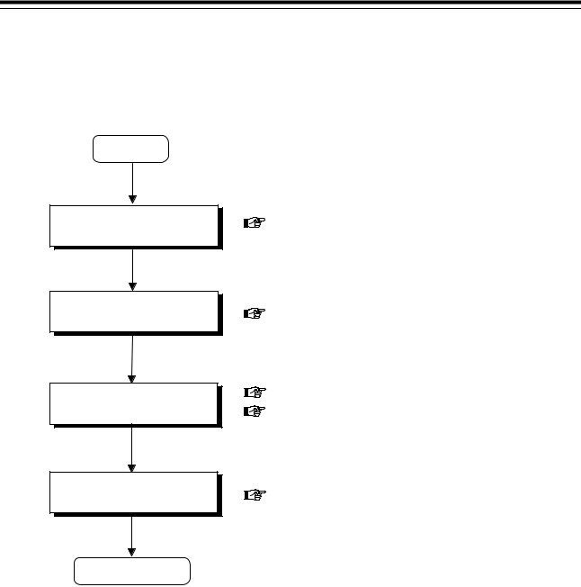
!"Initialization flowchart
Power ON
Change from RUN to STOP
Unlock the engineering mode
Setting the initial parameter
See 1.1 Transfer to Engineering Mode.
See 1.1 Transfer to Engineering Mode.
See 1.2 Procedure for Parameter Setting. See 2. DETAILS OF PARAMETER SETTING.
Lock the engineering mode |
See 1.3 End of Engineering Mode. |
End of initialization
IMR01H03-E4 |
1 |
1. PROCEDURE FOR INITIALIZATION
1.1 Transfer to Engineering Mode
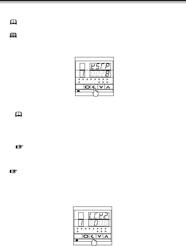
MA900 is used in the below figures for explanation, but the same setting procedures also apply to MA901.
The parameter of engineering mode can be changed only in the control STOP state.
1.Press the <R/S key with states of the PV/SV monitor mode for 1 second, to change the STOP from RUN.
CH |
PV |
|
AREA |
SV |
|
C H |
SET |
R/S |
MA900 |
|
|
STOP display
If set to the STOP state (dSTP) by the contact input, no parameters in Engineering mode can be changed. They can be changed in case of the following.
•The instrument changed the STOP state (KSTP) by the key operation.
•The instrument changed the STOP state by both the key operation and contact input operation.
For the RUN/STOP transfer, see the Instruction Manual (IMR01H01-E#)
2.Press the <R/S key while pressing the SET key with the PV/SV monitor mode change the instrument to setup setting mode.
For the setup setting mode, see Instruction Manual (IMR01H01-E#).
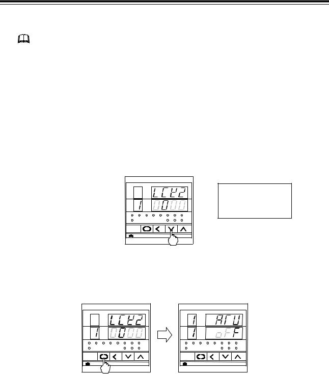
3.Press the SET key several times to change to the lock level 2 display (LCK2).
4.Press the < R/S key to light brightly the hundreds digit on the SV display.
CH |
PV |
|
AREA |
SV |
|
C H |
SET |
R/S |
MA900 |
|
|
Lock level 2 display
2 |
IMR01H03-E4 |
1. PROCEDURE FOR INITIALIZATION
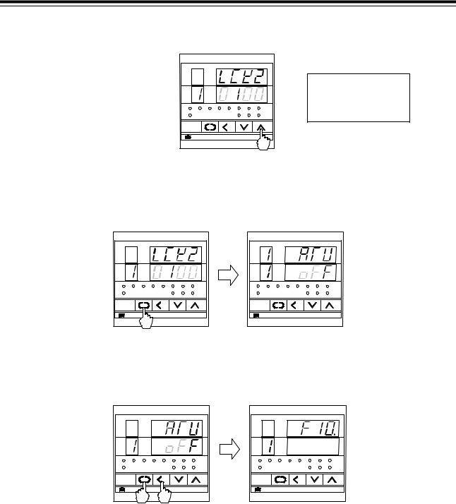
5. Press the UP key to change 0 to 1 in the hundreds digit.
CH |
PV |
|
AREA |
SV |
|
C H |
SET |
R/S |
MA900 |
|
|
Lock level 2 display
Set value 0000: Lock
0100: Unlock
6.Press the SET key to unlock the engineering mode. The display changes to the first parameter in setup setting mode.
CH |
PV |
|
AREA |
SV |
|
C H |
SET |
R/S |
MA900 |
|
|
Lock level 2 display
CH |
PV |
|
AREA |
SV |
|
C H |
SET |
R/S |
MA900 |
|
|
Autotuning display
7.Press the <R/S key for 2 seconds while pressing the SET key to change the engineering mode. The display changes to the function block F10.
CH |
PV |
|
AREA |
SV |
|
C H |
SET |
R/S |
MA900 |
|
|
Autotuning display
CH |
PV |
|
AREA |
SV |
|
C H |
SET |
R/S |
MA900 |
|
|
Function block F10 display Engineering mode
IMR01H03-E4 |
3 |
1. PROCEDURE FOR INITIALIZATION
1.2 Procedure for Parameter Setting
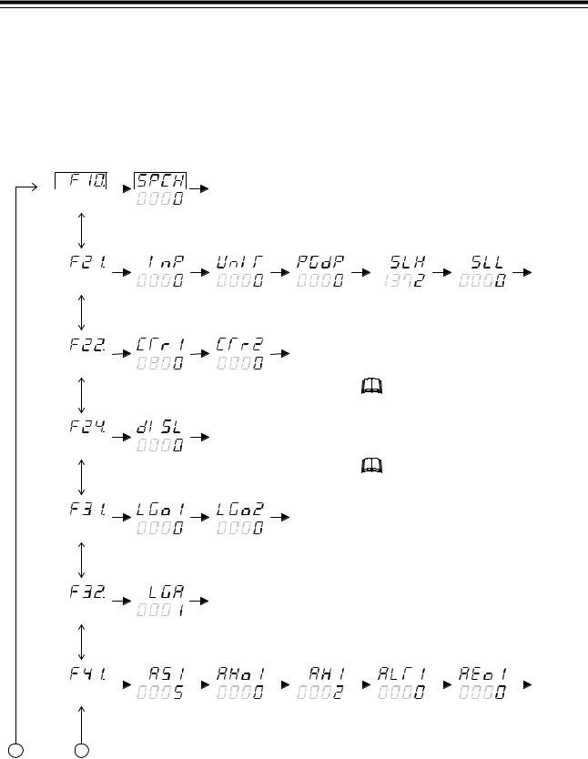
!"Flowchart of displaying parameter items
Display flowcharts in engineering mode are shown in the following.
[  : Press the SET key
  : Press the UP or DOWN key]
STOP display selection
PV
SV |
|
|
|
|
|
|
|
Return to the F10 |
|
|
|
|
|||
|
|
|
|
|
|
|
|
|
|
|
|||||
|
|
|
|
|
|
|
|
|
|
|
|||||
|
|
|
|
|
|
|
|
|
|
|
|
|
|||
|
|
|
|
|
|
|
|
|
|
|
|
|
|||
|
(F10.) |
(SPCH) |
|
|
|
|
|
|
|
|
|||||
|
|
|
|
|
Input type |
Display unit |
Decimal point |
||||||||
|
|
|
|
|
selection |
selection |
position setting |
||||||||
|
|
|
|
|
|
|
|
|
|
|
|
|
|
|
|
|
|
|
|
|
|
|
|
|
|
|
|
|
|
|
|
|
|
|
|
|
|
|
|
|
|
|
|
|
|
|
|
|
|
|
|
|
|
|
|
|
|
|
|
|
|
|
|
|
(F21.) |
(InP) |
|
(UnIT) |
|
(PGdP) |
|||||||||
|
|
|
|
|
CT ratio 1 |
|
CT ratio 2 |
|
|
|
|
||||
|
|
|
|
|
selection |
|
selection |
|
|
|
|
||||
|
|
|
|
|
|
|
|
|
|
|
|
Return to the F22. |
|||
|
|
|
|
|
|
|
|
|
|
|
|
||||
|
|
|
|
|
|
|
|
|
|
|
|
||||
|
|
|
|
|
|
|
|
|
|
|
|
||||
|
(F22.) |
|
(CTr1) |
|
(CTr2) |
|
|
|
|
||||||
|
|
|
|
|
Contact input |
|
|
|
|
|
|
|
|
||
|
|
|
|
|
logic selection |
|
|
|
|
|
|
|
|
||
|
|
|
|
|
|
|
|
Return to the F24. |
|
|
|
|
|||
|
|
|
|
|
|
|
|
|
|
|
|
||||
|
|
|
|
|
|
|
|
|
|
|
|
||||
|
|
|
|
|
|
|
|
|
|
|
|
|
|||
|
(F24.) |
(dlSL) |
|
|
|
|
|
|
|
|
|
||||
|
|
|
|
|
Control output |
|
Control output |
|
|
|
|
||||
|
|
|
|
|
logic selection 1 |
|
logic selection 2 |
|
|
|
|
||||
|
|
|
|
|
|
|
|
|
|
|
|
Return to the F31. |
|||
|
|
|
|
|
|
|
|
|
|
|
|
||||
|
|
|
|
|
|
|
|
|
|
|
|
||||
|
|
|
|
|
|
|
|
|
|
|
|
||||
|
(F31.) |
|
|
|
(LGo1) |
|
|
(LGo2) |
|
|
|
|
|||
|
|
|
|
|
Alarm output |
|
|
|
|
|
|
|
|
||
|
|
|
|
|
logic selection |
|
|
|
|
|
|
|
|
||
|
|
|
|
|
|
|
|
Return to the F32. |
|
|
|
|
|||
|
|
|
|
|
|
|
|
|
|
|
|
||||
|
|
|
|
|
|
|
|
|
|
|
|
||||
|
|
|
|
|
|
|
|
|
|
|
|
|
|||
|
(F32.) |
(LGA) |
|
|
|
|
|
|
|
|
|||||
|
|
|
|
|
Alarm type |
|
Alarm hold |
|
Alarm differential |
||||||
|
Alarm 1 |
selection |
|
action selection |
|
gap setting |
|||||||||
|
|
|
|
|
|
|
|
|
|
|
|
|
|
|
|
|
|
|
|
|
|
|
|
|
|
|
|
|
|
|
|
|
|
|
|
|
|
|
|
|
|
|
|
|
|
|
|
|
|
|
|
|
|
|
|
|
|
|
|
|
|
|
|
|
(F41.) |
(AS1) |
|
|
|
(AHo1) |
|
|
|
(AH1) |
|
|
|||
Setting limiter |
Setting limiter |
||
(high limit) setting |
(low limit) setting |
||
|
|
|
Return to the |
|
|
|
|
|
|
|
F21. |
|
|
|
|
|
|
|
|
(SLH) |
(SLL) |
||
Any parameter whose channel number is displayed can be set for each channel. (Check the channel number on the channel display of instrument.)
All of the channels can be simultaneously set as the same value.
All the setting item is displayed regard less of the contents of the instrument specification.
Alarm timer |
|
|
|
Action selection at |
|||
setting |
|
|
|
input error |
|||
|
|
|
|
|
|
|
Return to the |
|
|
|
|
|
|
|
|
|
|
||||||
|
|
|
|
|
|
|
F41. |
|
|
|
|
|
|
|
|
(ALT1) |
|
|
|
(AEo1) |
|
|
|
A B
4 |
IMR01H03-E4 |
1. PROCEDURE FOR INITIALIZATION
A |
B |
|
|
|
|
|
|
|
|
|
|
|
|
|
|
|
|
|
|
|
|
|||
|
|
|
|
|
Alarm type |
Alarm hold |
|
Alarm differential |
Alarm timer |
|
|
|
Action selection at |
|||||||||||
|
Alarm 2 |
selection |
action selection |
|
gap setting |
setting |
|
|
|
input error |
||||||||||||||
|
|
|
|
|
|
|
|
|
|
|
|
|
|
|
|
|
|
|
|
|
|
|
|
Return to the |
|
|
|
|
|
|
|
|
|
|
|
|
|
|
|
|
|
|
|
|
|
|
|
|
|
|
|
|
|
|
|
|
|
|
|
|
|
|
|
|
|
|
|
|
||||||
|
|
|
|
|
|
|
|
|
|
|
|
|
|
|
|
|
|
|
|
|
|
|
|
F42. |
|
|
|
|
|
|
|
|
|
|
|
|
|
|
|
|
|
|
|
|
|
|
|
|
|
|
(F42.) |
(AS2) |
(AHo2) |
|
(AH2) |
(ALT2) |
|
|
|
(AEo2) |
||||||||||||||
|
|
|
|
|
Alarm type |
Alarm hold |
|
Alarm differential |
Alarm timer |
|
|
|
Action selection at |
|||||||||||
|
Alarm 3 |
selection |
action selection |
|
gap setting |
setting |
|
|
|
input error |
||||||||||||||
|
|
|
|
|
|
|
|
|
|
|
|
|
|
|
|
|
|
|
|
|
|
|
|
Return to the |
|
|
|
|
|
|
|
|
|
|
|
|
|
|
|
|
|
|
|
|
|
|
|
|
F43. |
|
|
|
|
|
|
|
|
|
|
|
|
|
|
|
|
|
|
|
||||||
|
|
|
|
|
|
|
|
|
|
|
|
|
|
|
|
|
|
|
|
|
|
|
|
|
|
(F43.) |
(AS3) |
(AHo3) |
|
(AH3) |
(ALT3) |
|
|
|
(AEo3) |
||||||||||||||
|
|
|
|
|
Control action |
ON/OFF action |
|
|
|
|
|
|
|
|
|
|
|
|
|
|||||
|
|
|
|
|
type selection |
differential gap setting |
|
|
|
|
|
|
|
|
||||||||||
|
|
|
|
|
|
|
|
|
|
|
|
Return to the F51. |
|
|
|
|
|
|
|
|
||||
|
|
|
|
|
|
|
|
|
|
|
|
|
|
|
|
|
|
|
|
|||||
|
|
|
|
|
|
|
|
|
|
|
|
|
|
|
|
|
|
|
|
|||||
|
|
|
|
|
|
|
|
|
|
|
|
|
|
|
|
|
|
|
|
|
|
|
|
|
(F51.)
(F61.)
(oS) (oH)
Communication |
RUN/STOP transfer |
|
|
||||||
protocol selection |
logic selection |
|
|
||||||
|
|
|
|
|
|
|
|
Return to the F61. |
|
|
|
|
|
|
|
|
|
|
|
|
|
|
|
|
|
|
|
|
|
(CMPS) |
(CMLG) |
|
|
||||||
|
|
|
|
Integrated operating |
Integrated operating |
|
|||
ROM version |
time display |
time display |
Holding peak ambient |
||||||
display |
(Upper 3 digits) |
(Lower 4 digits) |
temperature display |
||||||
 Return to the F91.
(F91.) |
(E261) |
(WTH) |
(WTL) |
(TCJ) |
IMR01H03-E4 |
5 |
1. PROCEDURE FOR INITIALIZATION
!"Example of changing the setting
As setting procedure example, show procedure at setting with each channel (Usual setting) and channel common (Batch setting).
MA900 is used in the below figures for explanation, but the same setting procedures also apply to MA901.
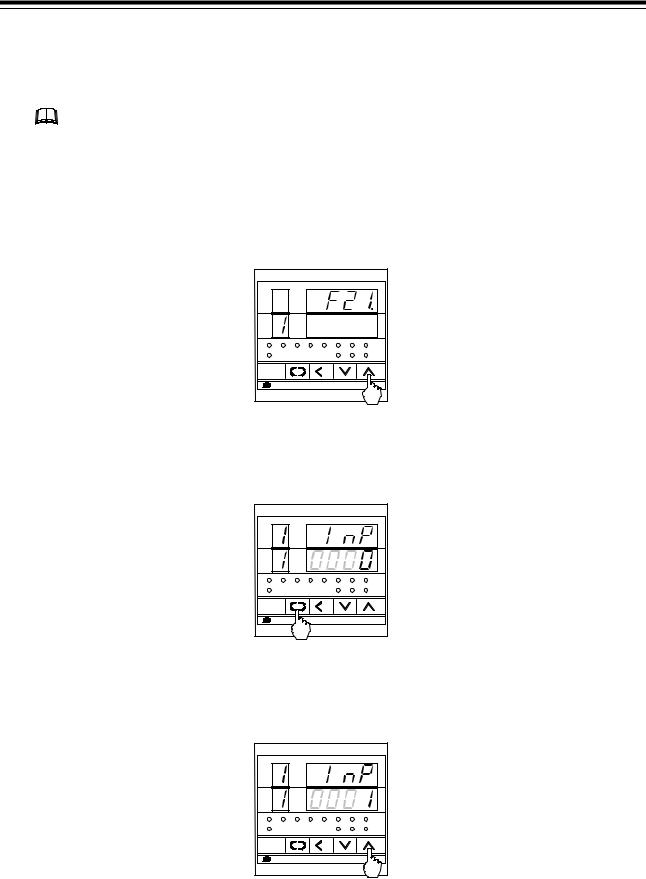
Example 1:
The following procedure is for changing the CH1 input type from “K” to “J.” (Usual setting)
1. Press the UP key to change the display to F21.
CH |
PV |
|
AREA |
SV |
|
C H |
SET |
R/S |
MA900 |
|
|
Function block display
2. Press the SET key to change to input type selection (InP).
CH |
PV |
|
AREA |
SV |
|
C H |
SET |
R/S |
MA900 |
|
|
Input type selection
3. Press the UP key to enter 1 in the least significant digit of the set value (SV) display.
CH |
PV |
|
AREA |
SV |
|
C H |
SET |
R/S |
MA900 |
|
|
Input type selection
6 |
IMR01H03-E4 |
1. PROCEDURE FOR INITIALIZATION
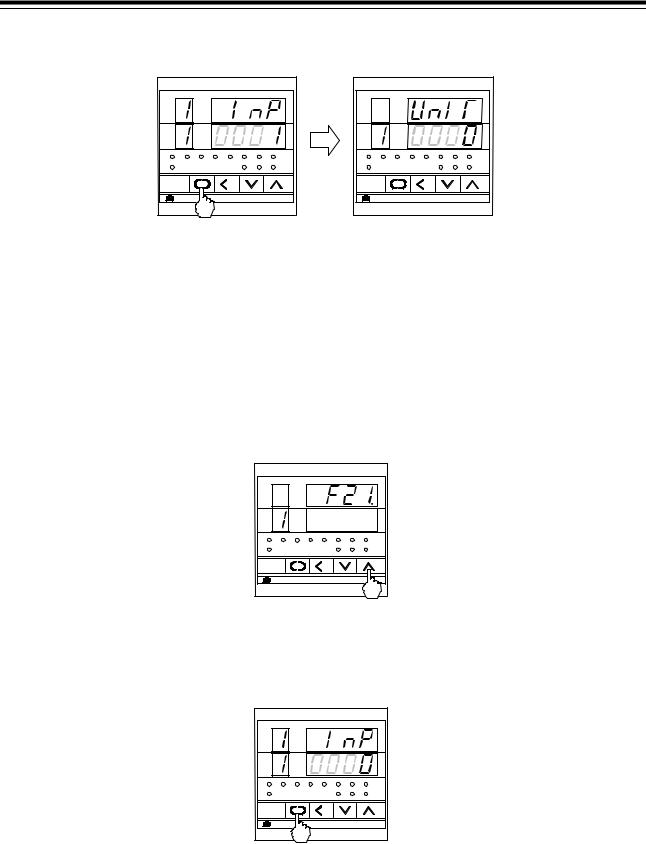
4. Press the SET key to register the value thus set. The display changes to the next parameter.
CH |
PV |
|
AREA |
SV |
|
C H |
SET |
R/S |
MA900 |
|
|
CH |
PV |
|
AREA |
SV |
|
C H |
SET |
R/S |
MA900 |
|
|
Input type selection |
Display unit selection |
Example 2:
The following procedure is for changing all channels of the input type from “K” to “J.” (Batch setting)
1. Press the UP key to change the display to F21.
CH |
PV |
|
AREA |
SV |
|
C H |
SET |
R/S |
MA900 |
|
|
Function block display
2. Press the SET key to change to input type selection (InP).
CH |
PV |
|
AREA |
SV |
|
C H |
SET |
R/S |
MA900 |
|
|
Input type selection
IMR01H03-E4 |
7 |
1. PROCEDURE FOR INITIALIZATION
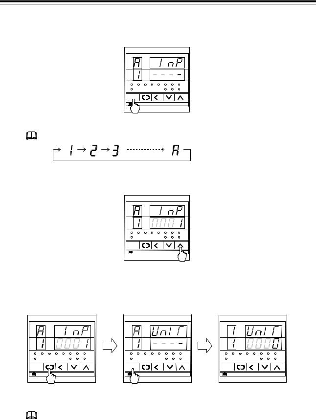
3.Press the CH key several times. Display the character A on the CH display and “----” on the SV display. The character A indicates that the batch setting.
CH |
PV |
|
AREA |
SV |
|
C H |
SET |
R/S |
MA900 |
|
|
Input type selection
Every time the CH key is pressed, the channel number changes as follows.
4.Press the UP key several times to enter 1 in the least significant digit of the set value (SV) display.
CH |
PV |
|
AREA |
SV |
|
C H |
SET |
R/S |
MA900 |
|
|
Input type selection
5.Press the SET key to register the value thus set. The display changes to the next parameter. Press the CH key to return to the usual setting from the batch setting.
CH |
PV |
|
AREA |
SV |
|
C H |
SET |
R/S |
MA900 |
|
|
Input type selection
CH |
PV |
|
AREA |
SV |
|
C H |
SET |
R/S |
MA900 |
|
|
Display unit selection
(Batch setting)
CH |
PV |
|
AREA |
SV |
|
C H |
SET |
R/S |
MA900 |
|
|
Display unit selection
(Usual setting)
If the selected parameter corresponds to the setting item in common to all channels, the simultaneous setting state returns to the normal setting state.
8 |
IMR01H03-E4 |
1. PROCEDURE FOR INITIALIZATION
1.3 End of Engineering Mode
MA900 is used in the above figures for explanation, but the same setting procedures also apply to MA901.
1.Transfer to function block symbol display (F## ) after each parameter is set.
2.Press the <R/S key for 2 seconds while pressing the SET key to change to the PV/SV monitor mode from the engineering mode.
3.Press the <R/S key while pressing the SET key with the PV/SV monitor mode change the instrument to setup setting mode.
4.Press the SET key several times to change to the lock level 2 display (LCK2).
5.Press the < R/S key to light brightly the hundreds digit on the SV display.
6.Press the DOWN key to change 1 to 0 in the hundreds digit.
CH |
PV |
|
AREA |
SV |
|
C H |
SET |
R/S |
MA900 |
|
|
Set value
0000: Lock
0100: Unlock
Lock level 2 display
7.Press the SET key to lock the engineering mode. The display changes to the first parameter in setup setting mode.
CH |
PV |
|
AREA |
SV |
|
C H |
SET |
R/S |
MA900 |
|
|
Lock level 2 display
CH |
PV |
|
AREA |
SV |
|
C H |
SET |
R/S |
MA900 |
|
|
Autotuning display
8.Press the <R/S key while pressing the SET key to change to the PV/SV monitor mode from the setup setting mode. Thus, the initialization ends.
IMR01H03-E4 |
9 |
2. DETAILS OF PARAMETER SETTING
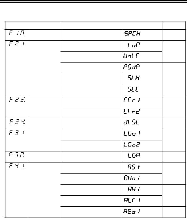
!"Parameter list
Function block |
Parameter |
|
Page |
|
|
Display function |
STOP display selection |
(SPCH) |
P. 17 |
(F10.) |
|
|
|
|
|
Input |
Input type selection |
(InP) |
P. 18 |
(F21.) |
specification |
|
|
|
|
|
Display unit selection |
(UnIT) |
|
|
|
Decimal point position selection |
(PGdP) |
P. 19 |
|
|
Setting limiter (high limit) |
(SLH) |
|
|
|
setting |
|
|
|
|
Setting limiter (low limit) |
(SLL) |
|
|
|
setting |
|
|
|
Current |
CT ratio 1 selection |
(CTr1) |
P. 20 |
(F22.) |
transformer (CT) |
|
|
|
|
input |
CT ratio 2 selection |
(CTr2) |
|
|
specification |
|
|
|
|
Contact input |
Contact input logic selection |
(dISL) |
P. 22 |
(F24.) |
specification |
|
|
|
|
Output function |
Control output logic selection 1 |
(LGo1) |
P. 24 |
(F31.) |
|
|
|
(MA900) |
|
|
Control output logic selection 2 |
(LGo2) |
P. 25 |
|
|
|
|
(MA901) |
|
Alarm output |
Alarm output logic selection |
(LGA) |
P. 26 |
(F32.) |
function |
|
|
|
|
Alarm 1 |
Alarm 1 type selection |
(AS1) |
P. 27 |
(F41.) |
function |
|
|
|
|
|
Alarm 1 hold action selection |
(AHo1) |
|
|
|
Alarm 1 differential gap setting |
(AH1) |
P.28 |
|
|
Alarm 1 timer setting |
(ALT1) |
|
|
|
Alarm 1 action selection at |
(AEo1) |
P. 29 |
|
|
input error |
|
|
Continued on the next page.
10 |
IMR01H03-E4 |

2. DETAILS OF PARAMETER SETTING
Continued from the previous page.
Function block |
Parameter |
|
Page |
|
|
Alarm 2 |
Alarm 2 type selection |
(AS2) |
P. 27 |
(F42.) |
function |
|
|
|
|
|
Alarm 2 hold action selection |
(AHo2) |
|
|
|
Alarm 2 differential gap setting |
(AH2) |
P. 28 |
|
|
Alarm 2 timer setting |
(ALT2) |
|
|
|
Alarm 2 action selection at |
(AEo2) |
P. 29 |
|
|
input error |
|
|
|
Alarm 3 |
Alarm 3 type selection |
(AS3) |
P. 27 |
(F43.) |
function |
|
|
|
|
|
Alarm 3 hold action selection |
(AHo3) |
|
|
|
Alarm 3 differential gap setting |
(AH3) |
P. 28 |
|
|
Alarm 3 timer setting |
(ALT3) |
|
|
|
Alarm 3 action selection at |
(AEo3) |
P. 29 |
|
|
input error |
|
|
|
Control action |
Control action type selection |
(oS1) |
P. 29 |
(F51.) |
|
|
|
|
|
|
ON/OFF action differential gap |
(oH) |
|
|
|
setting |
|
|
|
Communication |
Communication protocol |
(CMPS) |
P. 30 |
(F61.) |
function |
selection |
|
|
|
|
RUN/STOP transfer logic |
(CMLG) |
|
|
|
selection |
|
|
|
Displayed for |
ROM version display |
(E261) |
P. 31 |
(F91.) |
maintenance |
|
|
|
|
information |
Integrated operating time |
(WTH) |
|
|
|
(Upper 3 digits) display |
|
|
|
|
Integrated operating time |
(WTL) |
|
|
|
(Lower 4 digits) display |
|
|
|
|
Holding peak ambient |
(TCJ) |
|
|
|
temperature display |
|
|
IMR01H03-E4 |
11 |

2. DETAILS OF PARAMETER SETTING
2.1 Attention Items in Setting
If any of the following parameter is changed, the relevant set value is initialized or is automatically converted.
Before changing the set values, always record all of them (SV setting & CT monitor mode, setup setting mode, parameter setting mode and engineering mode).
After changing the set values, always check all of them (SV setting & CT monitor mode, setup setting mode, parameter setting mode and engineering mode).
!"When changed parameter of input type selection or engineering unit setting
When change a input type and unit, all the set value of a list shown below is initialized. Set it in value to use once again.
Mode |
Description |
|
Default value |
||
|
|
|
|
|
|
|
|
TC input |
RTD input |
|
Voltage input |
|
|
|
|
|
|
|
Decimal point position |
0 1 |
|
1 |
2 |
|
Setting limiter [high limit] |
Maximum |
settable value |
|
100.0 % |
|
Setting limiter [low limit] |
|
|
|
0.0 % |
|
Alarm 1 hold action |
0 (Without alarm hold |
action) |
||
|
Alarm 1 differential gap |
2 ° C [° F] |
2.0 ° C [° F] |
|
0.2 % of span |
|
Alarm 1 action at input error |
0 (Without action at input error) |
|||
Engineering |
Alarm 2 hold action |
0 (Without alarm hold action) |
|||
mode |
Alarm 2 differential gap |
2 ° C [° F] |
2.0 ° C [° F] |
|
0.2 % of span |
|
Alarm 2 action at input error |
0 (Without action at input error) |
|||
|
Alarm 3 hold action |
0 (Without alarm hold action) |
|||
|
Alarm 3 differential gap |
2 ° C [° F] |
2.0 ° C [° F] |
|
0.2 % of span |
|
Alarm 3 action at input error |
0 (Without action at input error) |
|||
|
ON/OFF action differential gap |
2 ° C [° F] |
2.0 ° C [° F] |
|
0.2 % of span |
|
Heater break alarm 1 |
|
OFF |
|
|
Setup setting |
Heater break alarm 2 3 |
|
OFF |
|
|
mode |
PV bias |
0 ° C [° F] |
0.0 ° C [° F] |
|
0.0 % |
|
Digital filter |
|
OFF |
|
|
10: No digit below decimal point
21: 1 digit below decimal point
3In case of MA901, this item is not provided.
Continued on the next page.
12 |
IMR01H03-E4 |

2. DETAILS OF PARAMETER SETTING
Continued from the previous page.
Mode |
Description |
|
Default value |
|
|
|
|
|
|
|
|
TC input |
RTD input |
Voltage input |
|
|
|
|
|
|
Control loop break alarm |
|
8.0 minutes |
|
|
Control loop break alarm |
0 ° C [° F] |
0.0 ° C [° F] |
0.0 % |
|
deadband |
|
|
|
|
Alarm 1 |
50 ° C [° F] |
50.0 ° C [° F] |
5.0 % of span |
|
Alarm 2 |
|
|
|
Parameter |
Alarm 3 |
|
|
|
setting mode |
Heat-side proportional band |
30 ° C [° F] |
30.0 ° C [° F] |
3.0 % of span |
|
Integral time |
|
240 seconds |
|
|
Derivative time |
|
60 seconds |
|
|
Anti-reset windup |
|
100 % |
|
|
Cool-side proportional band * |
100 % of heat-side proportional band |
||
|
Overlap/deadband * |
0 ° C [° F] |
0.0 ° C [° F] |
0.0 % |
|
Setting changing rate limiter |
|
OFF |
|
SV setting & |
Set value (SV) |
0 ° C [° F] |
0.0 ° C [° F] |
0.0 % |
CT monitor |
|
|
|
|
mode |
|
|
|
|
|
|
|
|
|
* In case of MA901, these items are not provided.
IMR01H03-E4 |
13 |
2. DETAILS OF PARAMETER SETTING
!"When changed parameter of decimal point position setting
When change a decimal point position, it is converted into about set value of a list shown below automatically. However, the set value may change as a result of changing the position of the decimal point. Therefore in that case, re-set it to the value to be used.
Mode |
Description |
|
|
|
Setting limiter [high limit] |
|
Setting limiter [low limit] |
Engineering mode |
Alarm 1 differential gap |
|
Alarm 2 differential gap |
|
Alarm 3 differential gap |
|
ON/OFF action differential gap |
Setup setting mode |
PV bias |
|
Control loop break alarm deadband |
|
Alarm 1 |
|
Alarm 2 |
Parameter setting mode |
Alarm 3 |
|
Heat-side proportional band |
|
Overlap/deadband * |
|
Setting changing rate limiter |
SV setting & CT monitor mode |
Set value (SV) |
* In case of MA901, this item is not provided.
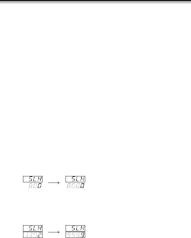
Example and caution of automatic conversion
•Decimal point location moves in accordance with it when increases decimal point location. Example: When the position of the decimal point changed from 0 to 1 with SLH set to 800 ° C.
(Changed from 800 to 800.0)
|
|
|
(SLH) |
|
(SLH) |
•If the setting range is not between − 1999 and + 9999 regardless of the position of the decimal point, it is limited by the range from − 1999 to + 9999.
Example: Suppose set SLH is 1372 ° C, if change decimal point position from 0 to 1.
SLH becomes 999.9 as it exceeds the setting range.
(SLH) (SLH)
Continued on the next page.
14 |
IMR01H03-E4 |
Loading...