


 Loading...
Digital Controller
FB100
Instruction Manual
RKC INSTRUMENT INC. |
IMR01W16-E7 |

Modbus is a registered trademark of Schneider Electric.
Company names and product names used in this manual are the trademarks or registered trademarks of the respective companies.
All Rights Reserved, Copyright 2008, RKC INSTRUMENT INC.

Thank you for purchasing this RKC product. In order to achieve maximum performance and ensure proper operation of your new instrument, carefully read all the instructions in this manual. Please place the manual in a convenient location for easy reference.
NOTICE
This manual assumes that the reader has a fundamental knowledge of the principles of electricity, process control, computer technology and communications.
The figures, diagrams and numeric values used in this manual are only for purpose of illustration.
RKC is not responsible for any damage or injury that is caused as a result of using this instrument, instrument failure or indirect damage.
RKC is not responsible for any damage and/or injury resulting from the use of instruments made by imitating this instrument.
Periodic maintenance is required for safe and proper operation of this instrument. Some components have a limited service life, or characteristics that change over time.
Every effort has been made to ensure accuracy of all information contained herein. RKC makes no warranty expressed or implied, with respect to the accuracy of the information. The information in this manual is subject to change without prior notice.
No portion of this document may be reprinted, modified, copied, transmitted, digitized, stored, processed or retrieved through any mechanical, electronic, optical or other means without prior written approval from RKC.
!WARNING
An external protection device must be installed if failure of this instrument could result in damage to the instrument, equipment or injury to personnel.
All wiring must be completed before power is turned on to prevent electric shock, fire or damage to instrument and equipment.
This instrument must be used in accordance with the specifications to prevent fire or damage to instrument and equipment.
This instrument is not intended for use in locations subject to flammable or explosive gases.
Do not touch high-voltage connections such as power supply terminals, etc. to avoid electric shock.
RKC is not responsible if this instrument is repaired, modified or disassembled by other than factory-approved personnel. Malfunction can occur and warranty is void under these conditions.
IMR01W16-E7 |
i-1 |


 CAUTION

This product is intended for use with industrial machines, test and measuring equipment. (It is not designed for use with medical equipment and nuclear energy.)
This is a Class A instrument. In a domestic environment, this instrument may cause radio interference, in which case the user may be required to take additional measures.
This instrument is protected from electric shock by reinforced insulation. Provide reinforced insulation between the wire for the input signal and the wires for instrument power supply, source of power and loads.
Be sure to provide an appropriate surge control circuit respectively for the following:
-If input/output or signal lines within the building are longer than 30 meters.
-If input/output or signal lines leave the building, regardless the length.
This instrument is designed for installation in an enclosed instrumentation panel. All high-voltage connections such as power supply terminals must be enclosed in the instrumentation panel to avoid electric shock by operating personnel.
All precautions described in this manual should be taken to avoid damage to the instrument or equipment.
All wiring must be in accordance with local codes and regulations.
All wiring must be completed before power is turned on to prevent electric shock, instrument failure, or incorrect action.
The power must be turned off before repairing work for input break and output failure including replacement of sensor, contactor or SSR, and all wiring must be completed before power is turned on again.
To prevent instrument damage or failure, protect the power line and the input/output lines from high currents with a protection device such as fuse, circuit breaker, etc.
Prevent metal fragments or lead wire scraps from falling inside instrument case to avoid electric shock, fire or malfunction.
Tighten each terminal screw to the specified torque found in the manual to avoid electric shock, fire or malfunction.
For proper operation of this instrument, provide adequate ventilation for heat dispensation.
Do not connect wires to unused terminals as this will interfere with proper operation of the instrument.
Turn off the power supply before cleaning the instrument.
Do not use a volatile solvent such as paint thinner to clean the instrument. Deformation or discoloration will occur. Use a soft, dry cloth to remove stains from the instrument.
To avoid damage to instrument display, do not rub with an abrasive material or push front panel with a hard object.
Do not connect modular connectors to telephone line.
When high alarm with hold action/re-hold action is used for Event function, alarm does not turn on while hold action is in operation. Take measures to prevent overheating which may occur if the control device fails.
FOR PROPER DISPOSAL
When disposing of each part used for this instrument, always follows the procedure for disposing of industrial wastes stipulated by the respective local community.
i-2 |
IMR01W16-E7 |

|
|
SYMBOLS |
Safety Symbols: |
||
|
|
: This mark indicates precautions that must be taken if there is danger of electric |
|
WARNING |
|
|
|
shock, fire, etc., which could result in loss of life or injury. |
|
|
: This mark indicates that if these precautions and operating procedures are not |
|
CAUTION |
|
|
|
taken, damage to the instrument may result. |
|
|
|
!: This mark indicates that all precautions should be taken for safe usage.
: This mark indicates important information on installation, handling and operating procedures.
: This mark indicates supplemental information on installation, handling and operating procedures.
: This mark indicates where additional information may be located.
Character Symbols:
0 |
1 |
2 |
3 |
4 |
5 |
6 |
7 |
8 |
9 |
Minus |
Period |
|
|
|
|
|
|
|
|
|
|
|
|
|
|
|
|
|
|
|
|
|
|
|
|
A |
B (b) |
C |
c |
D (d) |
E |
F |
G |
H |
I |
J |
K |
|
|
|
|
|
|
|
|
|
|
|
|
|
|
|
|
|
|
|
|
|
|
|
|
L |
M |
N (n) |
O (o) |
P |
Q (q) |
R (r) |
S |
T |
t |
U |
u |
|
|
|
|
|
|
|
|
|
|
|
|
|
|
|
|
|
|
|
|
|
|
|
|
V W X Y Z Degree Dash
Dim lighting
Bright lighting
Flashing
IMR01W16-E7 |
i-3 |

DOCUMENT CONFIGURATION
There are six manuals pertaining to this product. Please be sure to read all manuals specific to your application requirements. If you do not have a necessary manual, please contact RKC sales office, the agent, or download from the official RKC website.
The following manuals can be downloaded from the official RKC website: http://www.rkcinst.com/english/manual_load.htm.
Manual |
Manual Number |
Remarks |
FB100 Installation Manual |
IMR01W12-E |
This manual is enclosed with instrument. |
|
|
This manual explains the mounting and wiring, |
|
|
front panel name, and the operation mode |
|
|
outline. |
FB100 Quick Operation Manual |
IMR01W13-E |
This manual is enclosed with instrument. |
|
|
This manual explains the basic key operation, |
|
|
mode menu, and data setting. |
|
|
|
FB100 Parameter List |
IMR01W14-E |
This manual is enclosed with instrument. |
|
|
This list is a compilation of the parameter data |
|
|
of each mode. |
|
|
|
FB100 Communication Quick Manual |
IMR01W15-E |
This manual is enclosed with instrument. |
|
|
(Only FB100 provided with the communication |
|
|
function) |
|
|
This manual explains the connection method |
|
|
with host computer, communication |
|
|
parameters, and communication data (except |
|
|
for parameters in Engineering Mode). |
|
|
|
FB100 Instruction Manual |
IMR01W16-E7 |
This Manual. |
|
|
This manual explains the method of |
|
|
the mounting and wiring, the operation of |
|
|
various functions, and troubleshooting. |
|
|
|
FB100/FB400/FB900 |
IMR01W04-E |
This manual explains RKC communication |
Communication Instruction Manual * |
|
protocol (ANSI X3.28-1976), Modbus, and |
|
relating to the communication parameters |
|
|
|
|
|
|
setting. |
|
|
|
* Sold separately |
|
|
Read this manual carefully before operating the instrument. Please place the manual in a convenient location for easy reference.
i-4 |
IMR01W16-E7 |

CONTENTS
1. OUTLINE |
Page |
|
1-1 |
||
1.1 |
Features ....................................................................................................... |
1-2 |
1.2 |
Checking the Product ................................................................................... |
1-3 |
1.3 |
Model Code .................................................................................................. |
1-4 |
Suffix code.............................................................................................................. |
1-4 |
|
Quick start code 2 (Initial setting code) .................................................................. |
1-6 |
|
1.4 |
Parts Description .......................................................................................... |
1-8 |
1.5 |
Input/Output Functions ............................................................................... |
1-11 |
2. HANDLING PROCEDURE TO OPERATION .................... |
2-1 |
|
3. MOUNTING........................................................................ |
3-1 |
|
3.1 |
Mounting Cautions........................................................................................ |
3-2 |
3.2 |
Dimensions................................................................................................... |
3-3 |
3.3 |
Procedures of Mounting and Removing ....................................................... |
3-4 |
Mounting procedures.............................................................................................. |
3-4 |
|
Removing procedures ............................................................................................ |
3-4 |
|
4. WIRING .............................................................................. |
4-1 |
|
4.1 |
Wiring Cautions ............................................................................................ |
4-2 |
4.2 |
Terminal Layout............................................................................................ |
4-4 |
Isolations of input and output.................................................................................. |
4-5 |
|
4.3 |
Wiring of Each Terminal ............................................................................... |
4-6 |
4.3.1 Power supply..................................................................................................... |
4-6 |
|
4.3.2 Output 1 (OUT1)/Output 2 (OUT2).................................................................... |
4-7 |
|
4.3.3 Digital output 1, 2 (DO1, DO2) .......................................................................... |
4-9 |
|
4.3.4 Measured input (Thermocouple/RTD/Voltage/Current) .................................... |
4-9 |
|
4.3.5 Optional........................................................................................................... |
4-10 |
|
|
Optional function: A [Digital input (5 points)]..................................................... |
4-10 |
Optional function: B [Digital input (2 points) Remote setting input (1 point)] .4-11
Optional function: C [Digital input (2 points)
Feedback resistance input (1 point)] ................................ |
4-12 |
Optional function: D [Digital input (2 points) |
|
Current transformer input (2 points)] ................................ |
4-13 |
Optional function: E [Communication (1 point) Digital input (3 points) .......... |
4-14 |
Optional function: F [Communication (1 point) Digital input (1 point) |
|
Current transformer input (1 point)] .................................. |
4-15 |
Optional function: G [Communication (2 points)] .............................................. |
4-16 |
IMR01W16-E7 |
i-5 |

|
|
Page |
Optional function: H [Communication (1 point) |
|
|
|
Current transformer input (2 points)] ................................ |
4-17 |
Optional function: J |
[Communication (1 point) Digital input (1 point) |
|
|
Remote setting input (1 point)] ......................................... |
4-18 |
Optional function: 3, 4, 5, 6, 7, 8 |
|
|
|
[Digital input (1 point) Transmission output (1 point) |
|
|
Remote setting input (1 point)] ......................................... |
4-20 |
5. OPERATION MENU AND BASIC OPERATION ............... |
5-1 |
5.1 Operation Menu............................................................................................ |
5-2 |
Input type and input range display.......................................................................... |
5-3 |
5.2 Basic Operation ............................................................................................ |
5-4 |
5.2.1 Scrolling through parameters ............................................................................ |
5-4 |
SV setting & monitor mode ................................................................................. |
5-4 |
Parameter setting mode, Setup setting mode .................................................... |
5-6 |
Operation mode .................................................................................................. |
5-7 |
Engineering mode............................................................................................... |
5-8 |
5.2.2 Changing set value (SV) ................................................................................... |
5-9 |
5.2.3 Operation of the direct key .............................................................................. |
5-10 |
5.2.4 Data lock function............................................................................................ |
5-11 |
6. OPERATION ...................................................................... |
6-1 |
|
6.1 |
Operating Precautions.................................................................................. |
6-2 |
6.2 |
Monitoring Display in Operation.................................................................... |
6-3 |
|
When the Direct key type is other than Monitor ...................................................... |
6-3 |
|
When the Direct key type is Monitor ................................................................... |
6-4 |
6.3 |
Operating Setting.......................................................................................... |
6-5 |
6.3.1 Set the Set value (SV)....................................................................................... |
6-5 |
|
6.3.2 Set the Event set value (alarm set value) ......................................................... |
6-7 |
|
6.3.3 Autotuning (AT) start ......................................................................................... |
6-8 |
|
|
To manually set PID values ................................................................................ |
6-9 |
6.4 |
RUN/STOP Transfer................................................................................... |
6-11 |
RUN/STOP transfer by Front key operation......................................................... |
6-11 |
|
RUN/STOP transfer by Direct key operation ........................................................ |
6-12 |
|
RUN/STOP transfer by Digital input (DI) [optional]............................................... |
6-13 |
|
6.5 |
Autotuning (AT) .......................................................................................... |
6-15 |
Caution for using the Autotuning (AT) .................................................................. |
6-15 |
|
Requirements for Autotuning (AT) start................................................................ |
6-15 |
|
i-6 |
|
IMR01W16-E7 |

|
Page |
Requirements for Autotuning (AT) cancellation.................................................... |
6-15 |
Autotuning (AT) start/stop operation..................................................................... |
6-16 |
6.6 Startup Tuning (ST) .................................................................................... |
6-18 |
Caution for using the Startup tuning (ST) ............................................................. |
6-18 |
Requirements for Startup tuning (ST) start........................................................... |
6-19 |
Requirements for Startup tuning (ST) cancellation............................................... |
6-19 |
Startup tuning (ST) setting.................................................................................... |
6-20 |
6.7 Auto/Manual Transfer ................................................................................. |
6-23 |
Auto/Manual transfer by Front key operation ....................................................... |
6-24 |
Auto/Manual transfer by Direct key operation ...................................................... |
6-25 |
Auto/Manual transfer by Digital input (DI) [optional]............................................. |
6-26 |
Procedure for setting the Manipulated output value (MV) in Manual mode.......... |
6-28 |
6.8 Remote/Local Transfer ............................................................................... |
6-29 |
Remote/Local transfer by Front key operation ..................................................... |
6-29 |
Remote/Local transfer by Direct key operation .................................................... |
6-30 |
Remote/Local transfer by Digital input (DI) [optional] ........................................... |
6-31 |
6.9 Control Area Transfer ................................................................................. |
6-33 |
Control area transfer by Front key operation........................................................ |
6-34 |
Control area transfer by Direct key operation....................................................... |
6-35 |
Control area transfer by Digital input (DI) [optional] ............................................. |
6-36 |
Control area transfer by Area soak time (Ramp/Soak Control) ............................ |
6-38 |
6.10 Interlock Release...................................................................................... |
6-39 |
Interlock release method by Front key operation ................................................. |
6-40 |
Interlock release method by Digital input (DI) [optional]....................................... |
6-40 |
6.11 Start Action at Recovering Power Failure................................................. |
6-42 |
Hot/Cold start selection ........................................................................................ |
6-42 |
Start determination point ...................................................................................... |
6-42 |
6.12 Position Proportioning PID Control ........................................................... |
6-43 |
Setting flowchart................................................................................................... |
6-45 |
Setting procedures ............................................................................................... |
6-47 |
6.13 Ramp/Soak Control .................................................................................. |
6-52 |
Operation flowchart .............................................................................................. |
6-53 |
Settings before operation ..................................................................................... |
6-54 |
Operation procedures........................................................................................... |
6-56 |
6.14 Group Operation by the Intercontroller Communication ........................... |
6-61 |
6.14.1 Wiring method of the Intercontroller communication..................................... |
6-61 |
6.14.2 Common setting of the Intercontroller communication.................................. |
6-62 |
6.14.3 Group RUN/STOP function ........................................................................... |
6-64 |
Operation flowchart........................................................................................... |
6-64 |
Requirements for Group RUN/STOP................................................................ |
6-65 |
Group RUN/STOP operation and states........................................................... |
6-65 |
IMR01W16-E7 |
i-7 |

|
Page |
Settings before operation.................................................................................. |
6-66 |
Usage example................................................................................................. |
6-69 |
6.14.4 Automatic temperature rise function (with learning function) ........................ |
6-72 |
Requirements for automatic temperature rise learning start............................. |
6-73 |
Requirements for automatic temperature rise learning cancellation................. |
6-73 |
Requirements for automatic temperature rise start .......................................... |
6-74 |
Requirements for automatic temperature rise cancellation .............................. |
6-74 |
Operation flowchart........................................................................................... |
6-75 |
Settings before operation.................................................................................. |
6-76 |
Operation procedures ....................................................................................... |
6-79 |
6.14.5 Cascade control function............................................................................... |
6-81 |
Operation flowchart........................................................................................... |
6-82 |
Settings before operation.................................................................................. |
6-83 |
Adjustment after control starting ....................................................................... |
6-85 |
Operation procedures ....................................................................................... |
6-88 |
6.14.6 Ratio setting function..................................................................................... |
6-89 |
Operation flowchart........................................................................................... |
6-90 |
Settings before operation.................................................................................. |
6-91 |
Adjustment after control starting ....................................................................... |
6-93 |
Operation procedures ....................................................................................... |
6-96 |
Usage example................................................................................................. |
6-97 |
7. PARAMETER DESCRIPTION ........................................... |
7-1 |
7.1 SV Setting & Monitor Mode.......................................................................... |
7-2 |
7.1.1 Display sequence (When the Direct key type is other than Monitor) ..................... |
7-2 |
7.1.2 Display sequence (When the Direct key type is Monitor).................................. |
7-3 |
7.1.3 Monitor and setting item.................................................................................... |
7-4 |
7.2 Operation Mode.......................................................................................... |
7-14 |
7.2.1 Display sequence............................................................................................ |
7-14 |
7.2.2 Operation item................................................................................................. |
7-15 |
7.3 Parameter Setting Mode............................................................................. |
7-22 |
7.3.1 Display sequence............................................................................................ |
7-23 |
7.3.2 Parameter setting item .................................................................................... |
7-24 |
7.4 Setup Setting Mode .................................................................................... |
7-37 |
7.4.1 Display sequence............................................................................................ |
7-37 |
7.4.2 Setup setting item ........................................................................................... |
7-38 |
7.5 Engineering Mode ...................................................................................... |
7-52 |
7.5.1 Display sequence............................................................................................ |
7-52 |
7.5.2 Precaution against parameter change ............................................................ |
7-58 |
i-8 |
IMR01W16-E7 |
|
|
Page |
7.5.3 Engineering setting item |
.................................................................................. |
7-65 |
Function block 10 (F10.) ................................................................... |
[Display] |
7-65 |
Function block 11 (F11.) ............................................................... |
[Direct key] |
7-70 |
Function block 21 (F21.) ....................................................................... |
[Input] |
7-71 |
Function block 22 (F22.) ...................................... |
[Remote setting input type] |
7-79 |
Function block 23 (F23.) ........................................ |
[Digital input assignment] |
7-80 |
Function block 30 (F30.) .................................................................... |
[Output] |
7-81 |
Function block 33 (F33.) .............................................. |
[Transmission output] |
7-86 |
Function block 41 (F41.) .................................................................. |
[Event 1] |
7-88 |
Function block 42 (F42.) .................................................................. |
[Event 2] |
7-97 |
Function block 43 (F43.) ................................................................ |
[Event 3] |
7-101 |
Function block 44 (F44.) ................................................................ |
[Event 4] |
7-105 |
Function block 45 (F45.) ........................................... |
[Heater break alarm 1] |
7-112 |
Function block 46 (F46.) ........................................... |
[Heater break alarm 2] |
7-116 |
Function block 50 (F50.) ................................................ |
[Hot/Cold start etc.] |
7-119 |
Function block 51 (F51.) .............................................................. |
[Control 1] |
7-125 |
Function block 52 (F52.) .............................................................. |
[Control 2] |
7-140 |
Function block 53 (F53.) ....................... |
[Position proportioning PID control] |
7-152 |
Function block 54 (F54.) ...................................................... |
[Startup tuning] |
7-157 |
Function block 55 (F55.) ...................... |
[Group/Automatic temperature rise] |
7-159 |
Function block 60 (F60.) ...................................... |
[Communication protocol] |
7-162 |
Function block 70 (F70.) .............................................................. |
[Time unit] |
7-163 |
Function block 71 (F71.) ....................................................... |
[Setting limiter] |
7-164 |
Function block 91 (F91.) .................................................................. |
[Others] |
7-165 |
8. TROUBLESHOOTING....................................................... |
8-1 |
8.1 Error Display................................................................................................. |
8-2 |
Display when input error occurs ............................................................................. |
8-2 |
Self-diagnostic error ............................................................................................... |
8-3 |
8.2 Solutions for Problems ................................................................................. |
8-4 |
Display.................................................................................................................... |
8-5 |
Control.................................................................................................................... |
8-6 |
Operation................................................................................................................ |
8-8 |
Event function......................................................................................................... |
8-9 |
Heater break alarm (HBA).................................................................................... |
8-10 |
9. SPECIFICATIONS ............................................................. |
9-1 |
Measured input ................................................................................................... |
9-2 |
Remote setting (RS) input [optional]................................................................... |
9-3 |
Current transformer (CT) input [optional]............................................................ |
9-4 |
IMR01W16-E7 |
i-9 |

|
Page |
Feedback resistance (FBR) input [optional]........................................................ |
9-4 |
Digital input (DI) [optional] .................................................................................. |
9-5 |
Output (OUT1, OUT2) ........................................................................................ |
9-5 |
Digital output (DO1, DO2)................................................................................... |
9-6 |
Transmission output (AO) [optional] ................................................................... |
9-6 |
Performance (at the ambient temperature 23 ±2 C).......................................... |
9-7 |
Control ................................................................................................................ |
9-8 |
Brilliant II PID control .......................................................................................... |
9-8 |
Brilliant II Heat/Cool PID control ......................................................................... |
9-9 |
Brilliant II Position proportioning PID control without FBR................................ |
9-10 |
Event function [optional] ................................................................................... |
9-11 |
Control loop break alarm (LBA) [optional]......................................................... |
9-12 |
Heater break alarm (HBA) [time-proportional control output (optional)] ........... |
9-12 |
Heater break alarm (HBA) [continuous control output (optional)] ..................... |
9-12 |
Multi-memory area function [optional]............................................................... |
9-12 |
Loader communication ..................................................................................... |
9-13 |
Communication [optional] ................................................................................. |
9-13 |
Intercontroller communication function [optional] ............................................. |
9-14 |
Self-diagnostic function..................................................................................... |
9-15 |
Power................................................................................................................ |
9-15 |
General specifications ...................................................................................... |
9-16 |
Standard ........................................................................................................... |
9-17 |
APPENDIX ............................................................................ |
A-1 |
A. Removing the Internal Assembly................................................................... |
A-2 |
B. Replacing the Waterproof/Dustproof Rubber Packing................................... |
A-4 |
C. Current Transformer (CT) Dimensions.......................................................... |
A-6 |
D. Memory Area Data List ................................................................................. |
A-7 |
E. Parameter List............................................................................................... |
A-8 |
F. Seal [for Unit and Direct key] (accessory attached)..................................... |
A-24 |
INDEX.................................................................................... |
B-1 |
Alphabetical Order............................................................................................. |
B-2 |
Character Order................................................................................................. |
B-5 |
Revisions |
|
i-10 |
IMR01W16-E7 |

OUTLINE
1.1 |
Features ........................................................................................... |
1-2 |
1.2 |
Checking the Product ....................................................................... |
1-3 |
1.3 |
Model Code ...................................................................................... |
1-4 |
1.4 |
Parts Description .............................................................................. |
1-8 |
1.5 |
Input/Output Functions ................................................................... |
1-11 |
IMR01W16-E7 |
1-1 |

1.OUTLINE
1.1Features
This chapter describes features, package contents and model code, etc. The digital controller of this high performance type has the following features:
Panel space saving: 74 mm depth
Selectable sampling time among 50ms, 100ms, and 250 ms.
Selectable sampling time makes the FB100 suitable for any application ranging from pressure control requiring fast response to precise control requiring highest resolution. (Factory setting: 100 ms)
Selectable PID control algorithm
PID control algorithm is selectable in the FB100 to achieve the most precise control for various applications. PV derivative PID : suitable for fixed setpoint control (Factory setting)
Deviation derivative PID : suitable for ramp control using ramp-to-setpoint function and cascade control.
Advanced Heat/Cool PID algorithm with Undershoot Suppression
Startup tuning to eliminate time for autotuning
Mode switching can be performed directly (Direct key)
Control RUN/STOP, Auto/Manual, Remote/Local, Memory area, or monitor transfer can be selected. (Factory set value: Auto/Manual transfer)
Up to 8 recipes (multi-memory area) or Ramp/Soak control
FB100 can store up to 8 sets of control parameters. Ramp/Soak control is available by using the memory area function.
Easy maintenance
The internal assembly of the FB100 can be removed from the front.
NEMA4X and IP66 waterproof and dustproof protection for severe environments. (standard)
Two communication ports (optional)
Host communication can be performed with a host computer or host device such as an operation panel. (Communication 1)
Group operation such as cascade control and ratio setting is possible using only Intercontroller communication; it is not necessary to use communication with a host computer or analog signals such as remote setting input and transmission output.
(Communication 1 or Communication 2)
Easy-setup and Data Monitoring via a standard data port
The FB100 have the loader port (provided as standard) to connect to a PC USB port with Windows 2000/XP/Vista/7.
The standard port allows setup and data logging to be managed by the PC. The FB100 is recognized as an external device on the PC.
[The communication tool (WinUCI, PROTEM2) can be downloaded from the RKC official website: http://www.rkcinst.com/.]
1-2 |
IMR01W16-E7 |

1. OUTLINE
1.2 Checking the Product
Before using this product, check each of the following:
Model code
Check that there are no scratches or breakage in external appearance (case, front panel, or terminal, etc.)
Check that all of the items delivered are complete. (Refer to below)
|
Accessories |
Q’TY |
|
Remarks |
|
|
|
|
|
||
Instrument |
1 |
|
|
||
|
|
|
|
||
Mounting brackets (with screw) |
2 |
|
|
||
|
|
|
|
||
Seal (SAP-379) |
1 |
|
|
||
|
|
|
|
||
Case rubber packing (KRB100-39) |
1 |
For waterproof/dustproof |
|||
|
|
|
|
|
|
|
Installation Manual (IMR01W12-E) |
1 |
Enclosed with instrument |
||
|
|
|
|
|
|
|
Quick Operation Manual (IMR01W13-E) |
1 |
Enclosed with instrument |
||
|
|
|
|
|
|
|
Parameter List (IMR01W14-E) |
1 |
Enclosed with instrument |
||
|
|
|
|
|
|
|
Communication Quick Manual (IMR01W15-E) |
1 |
Enclosed with instrument |
||
|
|
|
(with communication function ) |
||
|
|
|
|
|
|
Instruction Manual (IMR01W16-E7) |
1 |
This manual |
This manual can be downloaded |
||
(sold separately) |
from the official RKC website: |
||||
|
|
|
|||
|
|
|
|
http://www.rkcinst.com/english/ |
|
|
|
|
|
||
|
Communication Instruction Manual (IMR01W04-E) |
1 |
Sold separately |
manual_load.htm. |
|
|
|
|
|
||
Terminal cover (KCA100-517) |
Depending on the |
Optional (sold separately) |
|||
|
|
order quantity |
|
|
|
Front cover (KRB100-36A) |
Depending on the |
Optional (sold separately) |
|||
|
|
order quantity |
|
|
|
Current transformer |
Depending on the |
Optional (sold separately) |
|||
|
(CTL-6-P-N [for 0 to 30 A] or |
order quantity |
|
|
|
|
|
|
|
||
|
CTL-12-S56-10L-N [for 0 to 100 A]) |
|
|
|
|
|
|
|
|
|
|
If any of the products are missing, damaged, or if your manual is incomplete, please contact RKC sales office or the agent.
IMR01W16-E7 |
1-3 |

1.OUTLINE
1.3Model Code
Check that the product received is correctly specified by referring to the following model code list: If the product is not identical to the specifications, please contact RKC sales office or the agent.
Suffix code
FB100 □ □ □ □ / □ □ □ □□□ /Y
(1) |
(2) |
(3) |
(4) |
(5) |
(6) |
(7) |
(8) |
(9) |
|
|
|
|
|
|
|
|
|
|
Specifications |
|
|
|
|
Suffix code |
||
|
|
|
|
|
Hardware coding only Quick start code 1 |
|||
|
(1) |
(2) |
(3) |
(4) |
(5) |
(6) |
(7) |
(8) |
(9) |
Relay contact output |
M |
|
|
|
|
|
|
|
|
|
Voltage pulse output |
V |
|
|
|
|
|
|
|
|
|
Voltage output (0 to 5 V DC) |
4 |
|
|
|
|
|
|
|
|
|
Voltage output (0 to 10 V DC) |
5 |
|
|
|
|
|
|
|
|
Output 1 (OUT1) |
Voltage output (1 to 5 V DC) |
6 |
|
|
|
|
|
|
|
|
|
Current output (0 to 20 mA DC) |
7 |
|
|
|
|
|
|
|
|
|
Current output (4 to 20 mA DC) |
8 |
|
|
|
|
|
|
|
|
|
Triac output |
T |
|
|
|
|
|
|
|
|
|
Open collector output |
D |
|
|
|
|
|
|
|
|
|
None |
|
N |
|
|
|
|
|
|
|
|
Relay contact output |
|
M |
|
|
|
|
|
|
|
|
Voltage pulse output |
|
V |
|
|
|
|
|
|
|
|
Voltage output (0 to 5 V DC) |
|
4 |
|
|
|
|
|
|
|
Output 2 (OUT2) |
Voltage output (0 to 10 V DC) |
|
5 |
|
|
|
|
|
|
|
Voltage output (1 to 5 V DC) |
|
6 |
|
|
|
|
|
|
|
|
|
|
|
|
|
|
|
|
|
||
|
Current output (0 to 20 mA DC) |
|
7 |
|
|
|
|
|
|
|
|
Current output (4 to 20 mA DC) |
|
8 |
|
|
|
|
|
|
|
|
Triac output |
|
T |
|
|
|
|
|
|
|
|
Open collector output |
|
D |
|
|
|
|
|
|
|
Power supply voltage |
24 V AC/DC |
|
3 |
|
|
|
|
|
|
|
100 to 240 V AC |
|
|
4 |
|
|
|
|
|
|
|
|
|
|
|
|
|
|
|
|||
|
None |
|
|
|
N |
|
|
|
|
|
|
Digital input (5 points) |
|
|
|
A |
|
|
|
|
|
|
Digital input (2 points) Remote setting input |
|
|
|
B |
|
|
|
|
|
|
Digital input (2 points) Feedback resistance input |
|
|
|
C |
|
|
|
|
|
|
Digital input (2 points) CT input (2 points) |
|
|
|
D |
|
|
|
|
|
|
Digital input (3 points) Communication (1 point) |
|
|
|
E |
|
|
|
|
|
|
Digital input (1 point) Communication (1 point) CT input (1 point) |
|
|
|
F |
|
|
|
|
|
Optional function |
Communication (2 points) * |
|
|
|
G |
|
|
|
|
|
Communication (1 point) CT input (2 points) |
|
|
|
H |
|
|
|
|
|
|
|
|
|
|
|
|
|
|
|
||
|
Communication (1 point) Digital input (1 point) Remote setting input |
|
|
|
J |
|
|
|
|
|
|
Digital input (1 point) Remote setting input Transmission output [Voltage output (0 to 1 V DC) |
3 |
|
|
|
|
|
|||
|
Digital input (1 point) Remote setting input Transmission output [Voltage output (0 to 5 V DC) |
4 |
|
|
|
|
|
|||
|
Digital input (1 point) Remote setting input Transmission output [Voltage output (0 to 10 V DC) |
5 |
|
|
|
|
|
|||
|
Digital input (1 point) Remote setting input Transmission output [Voltage output (1 to 5 V DC) |
6 |
|
|
|
|
|
|||
|
Digital input (1 point) Remote setting input Transmission output [Current output (0 to 20 mA DC) |
7 |
|
|
|
|
|
|||
|
Digital input (1 point) Remote setting input Transmission output [Current output (4 to 20 mA DC) |
8 |
|
|
|
|
|
|||
Case color |
White case |
|
|
|
|
N |
|
|
|
|
Black case |
|
|
|
|
A |
|
|
|
|
|
|
|
|
|
|
|
|
|
|
||
|
No quick start code (Configured to factory set value) |
|
|
|
|
|
N |
|
|
|
Quick start code |
Specify quick start code 1 |
|
|
|
|
|
1 |
|
|
|
|
Specify quick start code 1 and 2 (Refer to page 1-6) |
|
|
|
|
|
2 |
|
|
|
|
|
|
|
|
|
|
|
|
|
|
|
Quick start code 1 is not specified |
|
|
|
|
|
|
No code |
|
|
|
PID control with AT (Reverse action) |
|
|
|
|
|
|
|
|
|
|
|
|
|
|
|
|
|
|
|
|
|
PID control with AT (Direct action) |
|
|
|
|
|
|
|
|
|
Control Method |
Heat/Cool PID control with AT |
|
|
|
|
|
|
|
|
|
[Quick start code 1] |
Heat/Cool PID control with AT (for Extruder [air cooling]) |
|
|
|
|
|
|
A |
|
|
|
Heat/Cool PID control with AT (for Extruder [water cooling]) |
|
|
|
|
|
|
|
|
|
|
Position proportioning PID control without FBR (Reverse action) |
|
|
|
|
|
|
|
|
|
|
Position proportioning PID control without FBR (Direct action) |
|
|
|
|
|
|
C |
|
|
Measured input and Range |
Quick start code 1 is not specified |
|
|
|
|
|
|
|
No code |
|
[Quick start code 1] |
Refer to Range Code Table. |
|
|
|
|
|
|
|
|
|
Instrument specification |
Version symbol |
|
|
|
|
|
|
|
|
Y |
* When the optional function code "G" is selected, the factory set value of Communication 2 becomes Intercontroller communication.
1-4 |
IMR01W16-E7 |

1.3 Model Code
Range Code Table
[Thermocouple (TC) input, RTD input]
Type |
Code |
Measured range |
Code |
Measured range |
|
K35 |
200.0 to 400.0 C |
KC4 |
328.0 to 400.0 F |
|
K40 |
200.0 to 800.0 C |
KC6 |
250.0 to 800.0 F |
|
K41 |
200 to 1372 C |
KC5 |
328 to 2502 F |
K |
K09 |
0.0 to 400.0 C |
KA4 |
0.0 to 800.0 F |
|
K10 |
0.0 to 800.0 C |
KA1 |
0 to 800 F |
|
K14 |
0 to 300 C |
KA2 |
0 to 1600 F |
|
K02 |
0 to 400 C |
|
|
|
K04 |
0 to 800 C |
|
|
|
J27 |
200.0 to 400.0 C |
JC6 |
328.0 to 1200.0 F |
|
J32 |
200.0 to 800.0 C |
JC7 |
200.0 to 700.0 F |
|
J15 |
200 to 1200 C |
JB9 |
328 to 2192 F |
J |
J08 |
0.0 to 400.0 C |
JB6 |
0.0 to 800.0 F |
|
J09 |
0.0 to 800.0 C |
JA1 |
0 to 800 F |
|
J02 |
0 to 400 C |
JA2 |
0 to 1600 F |
|
J04 |
0 to 800 C |
|
|
T |
T19 |
200.0 to 400.0 C |
TC2 |
328.0 to 752.0 F |
E |
E21 |
200.0 to 700.0 C |
EA9 |
328.0 to 1292.0 F |
|
E06 |
200 to 1000 C |
EB1 |
328 to 1832 F |
S |
S06 |
50 to 1768 C |
SA7 |
58 to 3214 F |
R |
R07 |
50 to 1768 C |
RA7 |
58 to 3214 F |
B |
B03 |
0 to 1800 C |
BB2 |
0 to 3272 F |
N |
N02 |
0 to 1300 C |
NA7 |
0 to 3272 F |
PLII |
A02 |
0 to 1390 C |
AA2 |
0 to 2534 F |
W5Re/W26Re |
W03 |
0 to 2300 C |
WA2 |
0 to 4200 F |
U |
U04 |
0.0 to 600.0 C |
UB2 |
32.0 to 1112.0 F |
L |
L04 |
0.0 to 900.0 C |
LA9 |
32.0 to 1652.0 F |
Pt100 |
D34 |
100.00 to 100.00 C |
DD1 |
200.0 to 200.0 F |
|
D21 |
200.0 to 200.0 C |
DC8 |
199.99 to 199.99 F |
|
D35 |
200.0 to 850.0 C |
DC9 |
328.0 to 1562.0 F |
JPt100 |
P29 |
100.00 to 100.00 C |
PC8 |
199.99 to 199.99 F |
|
P30 |
200.0 to 640.0 C |
PC9 |
328.0 to 1184.0 F |
|
|
|
PD1 |
200.0 to 200.0 F |
[Voltage input, Current input]
Type |
Code |
Measured range |
0 to 10 mV DC |
101 |
|
0 to 100 mV DC |
201 |
|
0 to 1 V DC |
301 |
|
0 to 5 V DC |
401 |
Programmable range |
0 to 10 V DC |
501 |
19999 to 19999 |
1 to 5 V DC |
601 |
[The decimal point position is selectable] |
0 to 20 mA DC |
701 |
(Factory set value: 0.0 to 100.0) |
4 to 20 mA DC |
801 |
|
100 to 100 mV DC |
901 |
|
1 to 1 V DC |
902 |
|
10 to 10 mV DC |
903 |
|
IMR01W16-E7 |
1-5 |

1.3 Model Code
Quick start code 2 (Initial setting code)
Quick start code 2 tells the factory to ship with each parameter preset to the values detailed as specified by the customer. Quick start code is not necessarily specified when ordering, unless the preset is requested. These parameters are software selectable items and can be re-programmed in the field via the manual.
□□ □□ □ □ □ □ □ □ □
|
(1) |
(2) |
(3) |
(4) |
(5) |
(6) |
(7) |
(8) |
(9) |
|
|
|
|
|
|
||
|
|
|
|
|
|
|
|
|
|
|
|
|
|
|
|
|
|
|
Specifications |
|
|
|
|
|
|
|
Quick start code 2 (Initial setting code) |
|
|||||||
|
|
|
|
|
|
(1) |
|
(2) |
(3) |
|
(4) |
(5) |
(6) |
(7) |
|
(8) |
|
|
|
|
|
|
|
|
|
|
|
||||||||
Output assignment |
OUT1, OUT2, DO1, DO2 (Refer to Output Assignment Code Table) |
|
|
|
|
|
|
|
|
|
|
||||||
Digital input assignment |
DI1 to DI5 (Refer to Digital Input Assignment Code Table) |
|
|
|
|
|
|
|
|
|
|
|
|
||||
|
None |
|
|
|
|
|
|
|
N |
|
|
|
|
|
|
|
|
|
|
|
|
|
|
|
|
|
|
|
|
|
|
|
|
||
|
Voltage input (0 to 10 mV DC) |
|
|
|
|
|
|
1 |
|
|
|
|
|
|
|
|
|
|
Voltage input (0 to 100 mV DC) |
|
|
|
|
|
|
2 |
|
|
|
|
|
|
|
|
|
|
Voltage input (0 to 1 V DC) |
|
|
|
|
|
|
|
3 |
|
|
|
|
|
|
|
|
Remote setting input |
Voltage input (0 to 5 V DC) |
|
|
|
|
|
|
|
4 |
|
|
|
|
|
|
|
|
|
Voltage input (0 to 10 V DC) |
|
|
|
|
|
|
|
5 |
|
|
|
|
|
|
|
|
|
Voltage input (1 to 5 V DC) |
|
|
|
|
|
|
|
6 |
|
|
|
|
|
|
|
|
|
Current input (0 to 20 mA DC) |
|
|
|
|
|
|
7 |
|
|
|
|
|
|
|
|
|
|
Current input (4 to 20 mA DC) |
|
|
|
|
|
|
8 |
|
|
|
|
|
|
|
|
|
Event function 1 (EV1) |
None |
|
|
|
|
|
|
|
|
N |
|
|
|
|
|
|
|
Refer to Event Type Code Table |
|
|
|
|
|
|
|
|
|
|
|
|
|
|
|||
|
|
|
|
|
|
|
|
|
|
|
|
|
|
||||
Event function 2 (EV2) |
None |
|
|
|
|
|
|
|
|
|
|
N |
|
|
|
|
|
Refer to Event Type Code Table |
|
|
|
|
|
|
|
|
|
|
|
|
|
|
|
||
|
|
|
|
|
|
|
|
|
|
|
|
|
|
|
|||
Event function 3 (EV3) |
None |
|
|
|
|
|
|
|
|
|
|
|
N |
|
|
|
|
Refer to Event Type Code Table |
|
|
|
|
|
|
|
|
|
|
|
|
|
|
|
||
|
|
|
|
|
|
|
|
|
|
|
|
|
|
|
|||
|
None |
|
|
|
|
|
|
|
|
|
|
|
|
N |
|
|
|
Event function 4 (EV4) |
Refer to Event Type Code Table |
|
|
|
|
|
|
|
|
|
|
|
|
|
|
|
|
|
Control loop break alarm (LBA) |
|
|
|
|
|
|
|
|
|
|
|
5 |
|
|
|
|
|
CT1 (none), CT2 (none) |
|
|
|
|
|
|
|
|
|
|
|
|
|
N |
|
|
|
CT1 (CTL-6-P-N), CT2 (none) |
|
|
|
|
|
|
|
|
|
|
|
|
P |
|
||
CT type 1 |
CT1 (CTL-12-S56-10L-N), CT2 (none) |
|
|
|
|
|
|
|
|
|
|
|
|
S |
|
||
|
CT1 (CTL-6-P-N), CT2 (CTL-6-P-N) |
|
|
|
|
|
|
|
|
|
|
|
|
T |
|
||
|
CT1 (CTL-12-S56-10L-N), CT2 (CTL-12-S56-10L-N) |
|
|
|
|
|
|
|
|
|
|
U |
|
||||
|
None |
|
|
|
|
|
|
|
|
|
|
|
|
|
|
|
N |
Communication 1 protocol |
RKC communication (ANSI X3.28-1976) |
|
|
|
|
|
|
|
|
|
|
|
|
|
1 |
||
Modbus |
|
|
|
|
|
|
|
|
|
|
|
|
|
|
|
2 |
|
|
|
|
|
|
|
|
|
|
|
|
|
|
|
|
|
||
|
Intercontroller communication 2 |
|
|
|
|
|
|
|
|
|
|
|
|
|
|
A |
|
1If the CT type is not specified, the instrument is shipped with the CT input setting of “CTL-6-P-N.”
2Selectable in the case of optional function codes E, F, H, and J.
Output Assignment Code Table
Code |
Output 1 (OUT1) |
Output 2 (OUT2) |
Digital output 1 (DO1) |
Digital output 2 (DO2) |
01 |
Control output 1 |
Control output 2 |
Event output 1 (EV1) |
Event output 2 (EV2) |
02 |
Control output 1 |
Control output 2 |
Event output 1 (EV1) |
Event output 4 (EV4) |
03 |
Control output 1 |
Control output 2 |
Event output 1 (EV1) |
Heater break alarm (HBA) output |
04 |
Control output 1 |
Control output 2 |
Event output 1 (EV1) |
FAIL output (De-energized) |
05 |
Control output 1 |
Control output 2 |
Event output 4 (EV4) |
Heater break alarm (HBA) output |
06 |
Control output 1 |
Control output 2 |
Event output 4 (EV4) |
FAIL output (De-energized) |
07 |
Control output 1 |
Control output 2 |
Heater break alarm (HBA) output |
FAIL output (De-energized) |
08 |
Control output 1 |
Heater break alarm (HBA) output |
Event output 1 (EV1) |
Event output 2 (EV2) |
09 |
Control output 1 |
Heater break alarm (HBA) output |
Event output 1 (EV1) |
Event output 4 (EV4) |
10 |
Control output 1 |
Heater break alarm (HBA) output |
Event output 1 (EV1) |
FAIL output (De-energized) |
11 |
Control output 1 |
Heater break alarm (HBA) output |
Event output 4 (EV4) |
FAIL output (De-energized) |
12 |
Control output 1 |
FAIL output (De-energized) |
Event output 1 (EV1) |
Event output 2 (EV2) |
13 |
Control output 1 |
FAIL output (De-energized) |
Event output 1 (EV1) |
Event output 4 (EV4) |
14 |
Control output 1 |
Event output 1 (EV1) |
Event output 2 (EV2) |
Event output 3 (EV3) |
15 |
Control output 1 |
Event output 4 (EV4) |
Event output 1 (EV1) |
Event output 2 (EV2) |
Energized/De-energized is configurable except for the FAIL output. (Factory shipment: Energized)
When Current transformer (CT) input is two-point input, Heater break alarm (HBA) output is OR output.
Invalid for a non-existing output/event function.
When used as Heat/Cool PID control, select any code of 1 to 7.
For Position proportioning PID control, output 1 (OUT1) is open-side output and output 2 (OUT2) is close-side output, regardless of the above selection.
1-6 |
IMR01W16-E7 |

1.3 Model Code
Digital Input Assignment Code Table
Code |
Digital input 1 |
Digital input 2 |
Digital input 3 |
Digital input 4 |
Digital input 5 |
Selectable |
|
(DI1) |
(DI2) |
(DI3) |
(DI4) |
(DI5) |
Optional function |
||
|
|||||||
01 |
Unused |
Unused |
Unused |
Unused |
Unused |
|
|
02 |
Memory area number selection (1 to 8) |
Memory area set |
RUN/STOP transfer |
|
|||
03 |
Memory area number selection (1 to 8) |
Memory area set |
Unused |
|
|||
04 |
Memory area number selection (1 to 8) |
Memory area set |
Auto/Manual transfer |
|
|||
05 |
Memory area number selection (1 to 8) |
Memory area set |
Interlock release |
|
|||
06 |
Memory area number selection (1 to 8) |
RUN/STOP transfer |
Unused |
A |
|||
07 |
Memory area number selection (1 to 8) |
RUN/STOP transfer |
Auto/Manual transfer |
||||
|
|||||||
08 |
Memory area number selection (1 to 8) |
RUN/STOP transfer |
Interlock release |
|
|||
09 |
Memory area number selection (1 to 8) |
Unused |
Auto/Manual transfer |
|
|||
10 |
Memory area number selection (1 to 8) |
Unused |
Interlock release |
|
|||
11 |
Memory area number selection (1 to 8) |
Auto/Manual transfer |
Interlock release |
|
|||
12 |
Memory area number selection (1 to 8) |
|
|
|
|||
13 |
RUN/STOP transfer |
Remote/Local transfer * |
Auto/Manual transfer |
|
|
|
|
14 |
RUN/STOP transfer |
Remote/Local transfer * |
Interlock release |
|
|
A, E |
|
15 |
RUN/STOP transfer |
Auto/Manual transfer |
Interlock release |
|
|
|
|
16 |
Remote/Local transfer * |
Auto/Manual transfer |
Interlock release |
|
|
|
|
17 |
RUN/STOP transfer |
Remote/Local transfer * |
|
|
|
|
|
18 |
RUN/STOP transfer |
Auto/Manual transfer |
|
|
|
|
|
19 |
RUN/STOP transfer |
Interlock release |
|
|
|
A, B, C, D, E |
|
20 |
Remote/Local transfer * |
Auto/Manual transfer |
|
|
|
||
|
|
|
|
||||
21 |
Remote/Local transfer * |
Interlock release |
|
|
|
|
|
22 |
Auto/Manual transfer |
Interlock release |
|
|
|
|
|
23 |
RUN/STOP transfer |
|
|
|
|
|
|
24 |
Remote/Local transfer * |
|
|
|
|
A, B, C, D, E, F, J, |
|
25 |
Auto/Manual transfer |
|
|
|
|
3, 4, 5, 6, 7, 8 |
|
26 |
Interlock release |
|
|
|
|
|
|
Memory area set: Switches to the memory area specified in DI1 – DI3 when the contact goes from open to closed. * When the optional function code A, C or D is selected, the Remote/Local transfer is invalid.
Event Type Code Table
Code |
Type |
Code |
Type |
Code |
Type |
A |
Deviation high |
H |
Process high |
V |
SV high |
B |
Deviation low |
J |
Process low |
W |
SV low |
C |
Deviation high/low |
K |
Process high with hold action |
1 |
MV1 high [heat-side] |
D |
Band |
L |
Process low with hold action |
2 |
MV1 low [heat-side] |
E |
Deviation high with hold action |
Q |
Deviation high with re-hold action |
3 |
MV2 high [cool-side] |
F |
Deviation low with hold action |
R |
Deviation low with re-hold action |
4 |
MV2 low [cool-side] |
G |
Deviation high/low with hold action |
T |
Deviation high/low with re-hold action |
|
|
IMR01W16-E7 |
1-7 |

1.OUTLINE
1.4Parts Description
This section describes various display units and the key functions.
Front Panel View
Manual (MAN) mode lamp (Green)
Measured value (PV) display
Memory area display 


Manipulated output (MV) lamp (Green)
Direct keys
Set (SET) key
Shift key
Remote (REM) mode lamp (Green)


 Autotuning (AT) lamp (Green)
Set value (SV) display
Output (OUT1, OUT2) lamp (Green)


 Digital output (DO1, DO2) lamp (Green)


 Alarm (ALM) lamp (Red)
Bar graph display
Up key
Down key
Display units
Measured value (PV) display |
[Green] |
Displays Measured value (PV) or various parameters’ symbols. |
|
|
|
Set value (SV) display |
[Orange] |
Displays Set value (SV), Manipulated output value (MV) or various |
|
|
parameters’ set values. |
|
|
|
Memory area display |
[Orange] |
Displays memory area number (1 to 8). |
|
|
|
Indication lamps
Manual (MAN) mode lamp |
[Green] |
Lights when operated in manual mode. |
|
|
|
|
|
Remote (REM) mode lamp |
[Green] |
Lights when operated in remote mode. |
|
|
|
|
|
Autotuning (AT) lamp |
[Green] |
Flashes when Autotuning is activated. |
|
|
|
(After autotuning is completed: AT lamp will go out) |
|
|
|
|
|
Manipulated output (MV) lamp |
[Green] |
Lights when operated in Manual mode. In this case, the Set value (SV) display |
|
|
|
shows the Manipulated output value (MV). |
|
|
|
|
|
Output (OUT1, OUT2) lamp |
[Green] |
Lights when the output corresponding to each lamp is ON. |
|
|
|
Lamp indication becomes as follows for current output or voltage output: |
|
|
|
For an output of less than 0 %: |
Extinguished |
|
|
For an output of more than 0 % but less than 100 %: Dimly lit |
|
|
|
For an output of more than 100 %: |
Lit |
Digital output (DO1, DO2) lamp [Green] |
Lights when the output corresponding to each lamp is ON. |
||
|
|
|
|
Alarm (ALM) lamp |
[Red] |
Lights when alarm (Event or Heater break alarm [HBA]) is turned ON. |
|
|
|
The type of alarm which is on can be checked on the event monitor screen. |
|
|
|
|
|


 These lamps work with event outputs (event function, HBA function, LBA function) which are assigned to OUT, DO and ALM.
1-8 |
IMR01W16-E7 |
1.4 Parts Description
Bar graph display [Green]
Manipulated output Displays the Manipulated output value (MV) [In the case of Position proportioning PID control, values (MV1, MV2) refer to below.]. When Manipulated output value (MV) is at 0 % or less, the left-end dot of the
[Factory set value] |
bar-graph flashes. When MV exceeds 100 %, the right-end dot flashes. |
||||||||||||||||||
|
[Example] 0 |
50 |
|
100 |
|||||||||||||||
|
|
|
|
|
|
|
|
|
|
|
|
|
|
|
|
|
|
|
|
Heat/Cool PID control:
When both OUT1 and OUT2 light, this means overlapping, but in this case the bar graph displays only the Manipulated output value (MV1) [heat-side].
Position proportioning PID control:
[With FBR input]
Displays the FBR input value (0.0 to 100.0 %).
[Without FBR input]
Cannot be used as a bar graph. The bar graph displays the over-scaled state (an output of more than 100 %). In this case, it is recommended to be set to “No display.”
[Example] |
0 |
50 |
|
100 |
|||||||||||||||
|
|
|
|
|
|
|
|
|
|
|
|
|
|
|
|
|
|
|
|
Flashing 
Measured value (PV) Displays the Measured value (PV). Scaling is available within the input range (Input scale low to Input scale high).
[Example] |
0 |
50 |
|
100 |
|||||||||||||||
|
|
|
|
|
|
|
|
|
|
|
|
|
|
|
|
|
|
|
|
Set value (SV) monitor Displays the Set value (SV). Scaling is available within the input range (Input scale low to Input scale high). Remote mode: Displays the remote setting value.
|
[Example] |
0 |
50 |
|
100 |
||||||||||||||||
|
|
|
|
|
|
|
|
|
|
|
|
|
|
|
|
|
|
|
|
|
|
|
|
||||||||||||||||||||
Deviation value |
Displays the deviation between the Measured value (PV) and the Set value (SV). When the |
||||||||||||||||||||
|
Deviation display is selected, the dots at both ends of bar-graph light. A display resolution per |
||||||||||||||||||||
|
dot is settable. (Bar graph display resolution: Refer to P. 7-68) |
||||||||||||||||||||
|
[Example] |
|
0 |
|
|
|
|
|
|
|
|
||||||||||
|
|
|
|
|
|
|
|
||||||||||||||
|
|
|
|
|
|
|
|
|
|
|
|
|
|
|
|
|
|
|
|
|
|
|
|
||||||||||||||||||||
Current transformer 1 |
Displays the input value (current value) of CT1 or CT2. (Unit: A) |
||||||||||||||||||||
(CT1) input value |
A display resolution per dot is settable. (Bar graph display resolution: Refer to P. 7-68) |
||||||||||||||||||||
Current transformer 2 |
[Example] |
0 |
50 |
|
100 |
||||||||||||||||
(CT2) input value |
|
|
|
|
|
|
|
|
|
|
|
|
|
|
|
|
|
|
|
|
|
|
|
|
|
|
|
|
|
|
|
|
|
|
|
|
|
|
|
|
|
|
|
The factory set value of the bar graph is “Manipulated output value.” Bar graph display type can be changed by the bar graph in the Engineering mode. (Refer to P. 7-66)
Direct keys
Pressing a direct key causes one of the operation changes below.
Auto/Manual transfer |
Switching the Auto/Manual control mode between Auto mode and Manual mode. |
[Factory set value] |
|
Monitor |
Use to switch the monitor screen. Pressing the direct key while any screen other than the SV |
|
setting & monitor mode screen is being displayed returns to the Measured value (PV)/Set value |
|
(SV) monitor screen. |
Memory area transfer |
Pressing the direct key changes to Memory area transfer screen. |
Remote/Local transfer |
Switching the Remote/Local control mode between Remote mode and Local mode. |
RUN/STOP transfer |
Switching the RUN/STOP mode between RUN and STOP status. |
To avoid damage to the instrument, never use a sharp object to press keys.
The factory default setting is Auto/Manual transfer. The Direct key type can be set in “Direct key type” (P. 7-70) of Engineering mode.
When the Direct key type is “Monitor”, the display of SV setting & monitor mode and the Direct key display are different from the other types. (Refer to P. 5-4)
Use/Unused of Direct key functions is programmable. (Refer to P. 7-70)
To prevent operator error, a Direct key cannot be operated in positioning adjustment (automatic adjustment).
IMR01W16-E7 |
1-9 |

1.4 Parts Description
Operation keys
Set (SET) key Used for parameter calling up and set value registration.
|
|
Shift key |
Shift digits when settings are changed. Used to selection operation between modes. |
|
|
||
|
|
|
|
|
|
Down key |
Decrease numerals. |
|
|
|
Keeping pressing the DOWN key makes numeric value change faster. (Manual mode) |
|
|
|
|
|
|
Up key |
Increase numerals. |
|
|
|
Keeping pressing the UP key makes numeric value change faster. (Manual mode) |
To avoid damage to the instrument, never use a sharp object to press keys.
Bottom View
Loader communication connector (Standard equipment)
Use our communication converter COM-K (sold separately) to connect FB100 and personal computer. Then, the cable (cable length: 1.5 meters) for connection between FB100 and our communication converter COM-K is optional.
Side view
Input select switch
Dip switch is used for the switching of the measured input type and the remote setting input type.
|
For the remote setting input |
|
Current input, |
Voltage (high) input |
|
Voltage (low) input |
||
|
||
|
For the measured input |
To change the input type, refer to Input type (P. 7-71), Remote setting input type (P. 7-79) in the Engineering mode.
1-10 |
IMR01W16-E7 |

1. OUTLINE
1.5 Input/Output Functions
This section describes the Input/Output functions of the instrument. To learn how to set each function, refer to the respective page.
Measured input
Digital input DI1 to DI5 [optional]
(Memory area selection, Area set, RUN/STOP, Remote/Local transfer, Auto/Manual transfer, Interlock release)
Remote setting (RS) input [optional]
Current transformer (CT) input [optional]
Feedback resistance (FBR) input [optional]

 Control output 1 (Heat-side/Open-side)

 Control output 2 (Cool-side/Close-side)

 Output of event function
 Heater break alarm output
Control
section |
Transmission output (AO) [optional] |
|
|
COM1 (RKC communication, Modbus, Intercontroller communication *) [optional]
COM2 (Intercontroller communication) [optional]
 Loader communication
* Can only be selected when one-point communication is used on the FB100.
Input On the FB100, Measured input, Digital input (DI), Remote setting (RS) input, Current transformer (CT) input, and Feedback resistance (FBR) input can be used.
Measured input [universal input]:
Input groups available for measured inputs are shown in the table below. (P. 7-71)
|
Thermocouple |
K, J, E, T, S, R, B, N, PLII, W5Re/W26Re, U, L |
|
Voltage (low) input |
RTD |
Pt100, JPt100 |
|
Voltage (low) |
0 to 1 V DC, 0 to 100 mV DC, 0 to 10 mV DC, |
||
group |
|||
|
100 to 100 mV DC, 10 to 10 mV DC |
||
|
|
||
|
Current |
0 to 20 mA DC, 4 to 20 mA DC |
|
Voltage (high) input group |
1 to 1 V DC, 0 to 5 V DC, 1 to 5 V DC, 0 to 10 V DC |
||
[Factory set value: Thermocouple K (When quick start code “N” is specified)
When the input type is changed, be sure to check the details of setting of the input group transfer and the input type selection by the input select switch. (P. 7-71)
Digital input [DI1 to DI5] (optional)
Digital input (contact input signal from the external devices) can be used for the following functions.
DI1 to 5 Memory area selection (number of area: 1 to 8) Area set, RUN/STOP, Remote/Local transfer, Auto/Manual transfer, Interlock release
For function assignment to the digital input, set the Digital input (DI) assignment (P. 7-80) in the Engineering mode.
IMR01W16-E7 |
1-11 |

1.5 Input/Output Functions
Remote setting (RS) input [universal input] (optional)
Remote input is to change a control set point by using current or voltage input from an external device.
Measured input is not isolated from Remote setting (RS) input.
Input groups available for Remote setting (RS) inputs are shown in the table below. (P. 7-79)
Voltage (low) input and Current input |
0 to 100 mV DC, |
0 to 10 mV DC, 0 to 1 V DC |
group |
0 to 20 mA DC, 4 to 20 mA DC |
|
Voltage (low) input group |
0 to 5 V DC, 1 to |
5 V DC, 0 to 10 V DC |
[Factory set value: Depend on model code] |
|
|
When using the Intercontroller communication (only slave controller of cascade control and ratio setting), the Remote setting (RS) input function becomes invalid.
Current transformer (CT) input (optional)
CT input is used for Heater break alarm function to detect a heater break or short-circuit.
Up to two CT inputs can be selected. (Specify when ordering)
Two types of CT available.
CTL-6-P-N (for 0 to 30 A)
CTL-12-S56-10L-N (for 0 to 100 A)
Measured input is not isolated from CT input.
If there is CT input, power frequency is automatically set by the power frequency detection function. However, no frequency may be able to be detected if at a CT value of less than 0.5 A.
Feedback resistance (FBR) input (optional)
When the control type is the Position proportioning PID control (with FBR input), a valve position from the control motor can be inputted to feedback resistance.
Measured input is not isolated from Feedback resistance (FBR) input.
Feedback resistance (FBR) input cannot be used with Current transformer (CT) input, Remote setting (RS) input and communication.
1-12 |
IMR01W16-E7 |

1.5 Input/Output Functions
Output Up to five outputs are available. They may be used as Control output
(OUT), Digital output (DO) or Transmission output (AO) by specifying the output type or by activating the output assignment function.
Output 1 (OUT1), Output 2 (OUT2)
The following output functions can be assigned to OUT1 and/or OUT2 at the output assignment of the Engineering mode (P. 7-82):
- Control output,
- Heater break alarm output, or
- FAIL (De-energized fixed: contact opens under FAIL)
For Heat/Cool PID control, OUT1 corresponds to the heat-side output and OUT2 corresponds to the cool-side output.
For Position proportioning PID control, OUT1 corresponds to the open-side output and OUT2 corresponds to the close-side output.
Output types available for OUT1 and OUT2 are shown in the table below. (Specify when ordering)
Relay contact output |
250 V AC 3 A (Resistive load), 30 V DC 1 A (Resistive load), 1a contact |
|
|
Voltage pulse output |
0/12 V DC (Allowable load resistance: 600 or more) |
|
|
Voltage output |
0 to 5 V DC, 1 to 5 V DC, 0 to 10 V DC (Allowable load resistance: 1 k or more) |
|
|
Current output |
0 to 20 mA DC, 4 to 20 mA DC (Allowable load resistance: 600 or less) |
|
|
Triac output |
0.5 A (Allowable load current) |
|
|
Open collector output |
30 V DC or less, 100 mA (Allowable load current), Sink type |
|
|
There is not isolation between OUT1 and OUT2.
When OUT1 and OUT2 can be used for relay contact output or triac output, there is isolation between each output (OUT1, OUT2, AO).
Digital output 1, 2 (DO1, DO2)
The following output functions can be assigned to DO1 through DO4 at the output assignment of the Engineering mode (P. 7-82):
-Output of event function,
-Heater break alarm output, or
-FAIL (De-energized fixed: contact opens under FAIL)
The output type for DO1 and DO2 is relay only. (Specify when ordering)
Relay contact output |
250 V AC 1 A (Resistive load), 30 V DC 1 A (Resistive load), 1a contact |
|
|
Transmission output (AO) [optional]
Output types available for transmission output are shown in the table below. (Specify when ordering)
Voltage output |
0 to 1 V DC, 0 to 5 V DC, 1 to 5 V DC, 0 to 10 V DC |
|
(Allowable load resistance: 1 k or more) |
Current output |
0 to 20 mA DC, 4 to 20 mA DC (Allowable load resistance: 600 or less) |
Parameter values shown in the following table can be output by Transmission output (P. 7-86). These transmission output data can be output after being scaled.
Measured value (PV) |
Set value (SV) monitor |
Deviation value |
Manipulated output value (MV1) |
Manipulated output value (MV2) |
Set value (SV) |
[heat-side] |
[cool-side] |
|
Remote setting (RS) input value |
|
|
Number of output: 1 point
IMR01W16-E7 |
1-13 |

1.5Input/Output Functions
Communication
Communication 1 (optional)
In this case of one-point communication, Host communication or Intercontroller communication can be selected. (This can be specified when the order is placed.)
In this case of two-point communication, this will be for Host communication.
Communication protocol is used for RKC communication (ANSI X3.28-1976) or Modbus. (Specify when ordering)
With Intercontroller communication, data can be exchanged between multiple FB100/400/900 instruments without using analog signals such as Remote setting input or Transmission output, or communication with a host computer. (Refer to P. 6-61)
Communication Interface: RS-485 only
The following four functions become usable when the Intercontroller
communication is used.
Automatic temperature rise function (with learning function) Cascade control function
Ratio setting function Group RUN/STOP function
For details of the Host communication, refer to the separate FB100/FB400/ FB900 Communication Instruction Manual (IMR01W04-E).
Communication 2 (optional)
This can be used only for two-point communication.
Communication 2 (COM2) is used for the Intercontroller communication. Data can be exchanged between two or more FB100s/400s/900s without using communication with analog signals such as Remote setting input and Analog output as well as with the host computer. (Refer to P. 6-61.)
Interface: RS-485 only
The following four functions become usable when the Intercontroller
communication is used.
Automatic temperature rise function (with learning function) Cascade control function
Ratio setting function Group RUN/STOP function
[Connection example]
When one-point communication is used
Host communication
Host computer
FB100 |
FB100 |
FB100 |
COM1 |
COM1 |
COM1 |
or
Intercontroller communication
FB100 |
|
FB100 |
|
FB100 |
COM1 |
|
COM1 |
|
COM1 |
|
|
|
|
|
When two-point communication is used
Host computer
COM1 |
FB100 |
COM2 |
Host communication
COM1 |
|
COM1 |
FB100 |
|
FB100 |
COM2 |
|
COM2 |
|
|
|
Intercontroller communication (Cascade control, etc.)
1-14 |
IMR01W16-E7 |
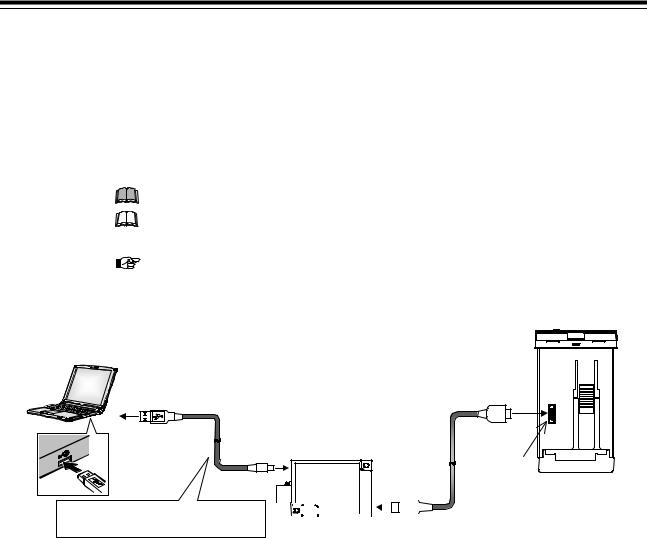
1.5 Input/Output Functions
Loader communication
It is possible to manage data on the personal computer side by converting all of the data in the FB100 into one file. 1
When starting the Loader communication, first your PC (Windows 2000/XP/ Vista/7) being used is necessary to be installed with the communication tool 2.
1Use our communication converter COM-K (sold separately) to connect FB100 and your PC.
2The communication tool (WinUCI, PROTEM2) can be downloaded from the RKC official website: http://www.rkcinst.com/.
The Loader port is only for parameter setup.
The Loader communication corresponds to the RKC communication protocol “Based on ANSI X3.28-1976 subcategories 2.5 and A4.”
For the COM-K, refer to the COM-K Instruction Manual (IMR01Z01-E).
[Connection example]
|
|
|
|
Connected to loader |
|
|
|
|
|
communication |
|
|
USB cable 1 m |
|
connector of the |
|
|
|
|
FB100 |
|
||
|
(COM-K accessory) |
Loader |
|
|
|
|
|
|
|
|
|
Connected to USB |
|
communication cable |
|
||
Connected to |
1.5 m (W-BV-01) |
|
|
||
port of a personal |
[COM-K optional] |
|
|
||
USB connecter |
Loader |
|
|||
computer |
|
|
|
||
|
USB |
|
communication |
|
|
|
|
|
|
||
|
|
|
connector |
|
|
|
|
communication |
FB100 bottom view |
||
|
|
converter |
|
|
|
|
|
COM-K |
|
|
|
|
Do not unplug the USB cable while the |
|
|
|
|
|
|
|
|
|
|
|
|
|
|
|
|
|
power to the instrument is ON. |
|
|
|
|
|
|
|
|
|
Connected to loader |
|
|||||
|
|
|
|
|
|
|
|
|
|
|
|
communication |
|
||||
|
|
|
|
|
|
|
|
|
|
|
|
|
|||||
Communication monitor tool WinUCI-A |
|
|
|
|
|
|
|
|
connecter |
The device address for |
|||||||
|
|
|
|
|
|
|
|
|
|
|
|
|
|||||
Software operation environment: Windows 2000 or higher |
|
|
|
|
|
|
|
|
|
|
|
|
|
Loader communication is |
|||
Communication setup tool WinUCI-B for FB series |
|
|
|
|
|
|
|
|
|
|
|
|
|
fixed at “0.” |
|||
|
|
|
|
|
|
|
|
|
|
|
|
|
The setting of the device |
||||
Software operation environment: Windows 2000 or higher |
|
|
|
|
|
|
|
|
|
|
|
|
|
||||
|
|
|
|
|
|
|
|
|
|
|
|
|
|
|
|
|
address is disregarded. |
Communication tool PROTEM2
Software operation environment: Windows XP (Service Pack 2) or higher PROTEM2 needs Microsoft .NET Framework 4.0 or later
Communication port of host computer USB port: Based on USB Ver. 2.0
Communication settings on the computer
(Values other than the communication port are fixed.)
Communication speed: 38400 bps
Start bit: |
1 |
Data bit: |
8 |
Parity bit: |
Without |
Stop bit: |
1 |
IMR01W16-E7 |
1-15 |
MEMO
1-16 |
IMR01W16-E7 |

HANDLING
PROCEDURE TO
OPERATION
IMR01W16-E7 |
2-1 |

2.HANDLING PROCEDURE TO OPERATION
2.HANDLING PROCEDURE TO OPERATION
This chapter describes procedures to set operating conditions of a customer and parameter of various setting modes.
Setting procedure to operation
Conduct necessary setting before operation according to the procedure described below.
Mounting and Wiring
When installing the instrument, refer to 3. MOUNTING (P. 3-1) and 4. WIRING (P. 4-1).
When group operation by using Intercontroller communication is performed, refer to 6.14.1 Wiring method of the Intercontroller communication (P. 6-61).
Entry to data sheet
Use the sheet of Appendix E, and make record of setting data of a customer.
Power ON
Change from RUN to STOP |
Change from RUN mode to STOP mode with the RUN/STOP transfer. (P. 6-11) |
|
Factory set value: RUN (control start) |
||
|
The parameters in Engineering mode which should be set according to the application are settable only when the controller is in STOP mode.
Setting of operating condition
(Engineering mode)
The parameters for controller’s basic functions in Engineering mode should be changed according to the application before setting the parameters related to operation.
Be sure to check the parameters for the following settings and change them according to the application if necessary. Other parameters should be also changed according to the application.
Power frequency [Factory set value 50Hz] (P. 7-78)
Input type (P. 7-71) 1, 2
Input scale high/low (P. 7-74) 1, 2
Control action (P. 7-125) 1, 2
Output assignment (P. 7-82) 1, 2
Remote setting input type (P. 7-79) 2
Event type (P. 7-88, 7-97, 7-101, 7-105) 2, 3
Transmission output type (P. 7-86) 3
Communication protocol (P. 7-162) 3
1This setting is not necessary when the quick start code "1" is specified.
2This setting is not necessary when the quick start code "2" is specified.
3This setting is not necessary when the quick start code "N" is specified.
When group operation by using Intercontroller communication is performed, set the following setting items.
Digital input (DI) assignment (P. 7-80) 1 |
Automatic temperature rise group (P. 7-159) 4 |
||
External input type (P. 7-121) 2, 3 |
|
|
RUN/STOP group (P. 7-160) 1, 4 |
Master channel selection (P. 7-122) 2, 3 |
|
|
|
1 Group RUN/STOP function (P.6-64) |
3 |
Ratio setting function (P. 6-89) |
|
2 Cascade control function (P. 6-81) |
4 |
Automatic temperature rise function (P. 6-72) |
|
Refer to 7.5. Engineering Mode (P. 7-52).
A
2-2 |
IMR01W16-E7 |
Loading...