

Page 1

r
RKC INSTRUMENT INC.
®
Module Type Controlle
SRZ
Instruction Manual
IMS01T04-E1
Page 2

Modbus is a registered trademark of Schneider Electric.
Company names and product names used in this manual are the trademarks or registered trademarks of
the respective companies.
All Rights Reserved, Copyright 2006, RKC INSTRUMENT INC.
Page 3

Thank you for purchasing this RKC instrument. In order to achieve maximum performance and ensure
proper operation of your new instrument, carefully read all the instructions in this manual. Please place this
manual in a convenient location for easy reference.
SYMBOLS
WARNING
CAUTION
!
: This mark indicates where additional information may be located.
An external protection device must be installed if failure of this instrument
could result in damage to the instrument, equipment or injury to personnel.
: This mark indicates precautions that must be taken if there is danger of electric
shock, fire, etc., which could result in loss of life or injury.
: This mark indicates that if these precautions and operating procedures are not taken,
damage to the instrument may result.
: This mark indicates that all precautions should be taken for safe usage.
: This mark indicates important information on installation, handling and operating
procedures.
: This mark indicates supplemental information on installation, handling and
operating procedures.
WARNING
!
All wiring must be completed before power is turned on to prevent electric
shock, fire or damage to instrument and equipment.
This instrument must be used in accordance with the specifications to
prevent fire or damage to instrument and equipment.
This instrument is not intended for use in locations subject to flammable or
explosive gases.
Do not touch high-voltage connections such as power supply terminals, etc.
to avoid electric shock.
RKC is not responsible if this instrument is repaired, modified or
disassembled by other than factory-approved personnel. Malfunction can
occur and warranty is void under these conditions.
IMS01T04-E1
i-1
Page 4

CAUTION
This is a Class A instrument. In a domestic environment, this instrument may cause radio
interference, in which case the user may be required to take adequate measures.
This instrument is protected from electric shock by reinforced insulation. Provide reinforced
insulation between the wire for the input signal and the wires for instrument power supply,
source of power and loads.
Be sure to provide an appropriate surge control circuit respectively for the following:
- If input/output or signal lines within the building are longer than 30 meters.
- If input/output or signal lines leave the building, regardless the length.
This instrument is designed for installation in an enclosed instrumentation panel. All
high-voltage connections such as power supply terminals must be enclosed in the
instrumentation panel to avoid electric shock by operating personnel.
All precautions described in this manual should be taken to avoid damage to the instrument or
equipment.
All wiring must be in accordance with local codes and regulations.
All wiring must be completed before power is turned on to prevent electric shock, instrument
failure, or incorrect action.
The power must be turned off before repairing work for input break and output failure including
replacement of sensor, contactor or SSR, and all wiring must be completed before power is
turned on again.
To prevent instrument damage or failure, protect the power line and the input/output lines from
high currents with a protection device such as fuse, circuit breaker, etc.
Prevent metal fragments or lead wire scraps from falling inside instrument case to avoid
electric shock, fire or malfunction.
Tighten each terminal screw to the specified torque found in the manual to avoid electric shock,
fire or malfunction.
For proper operation of this instrument, provide adequate ventilation for heat dispensation.
Do not connect wires to unused terminals as this will interfere with proper operation of the
instrument.
Turn off the power supply before cleaning the instrument.
Do not use a volatile solvent such as paint thinner to clean the instrument. Deformation or
discoloration will occur. Use a soft, dry cloth to remove stains from the instrument.
To avoid damage to instrument display, do not rub with an abrasive material or push front
panel with a hard object.
Do not connect modular connectors to telephone line.
NOTICE
This manual assumes that the reader has a fundamental knowledge of the principles of electricity,
process control, computer technology and communications.
The figures, diagrams and numeric values used in this manual are only for purpose of illustration.
RKC is not responsible for any damage or injury that is caused as a result of using this instrument,
instrument failure or indirect damage.
RKC is not responsible for any damage and/or injury resulting from the use of instruments made by
imitating this instrument.
Periodic maintenance is required for safe and proper operation of this instrument. Some components
have a limited service life, or characteristics that change over time.
Every effort has been made to ensure accuracy of all information contained herein. RKC makes no
warranty expressed or implied, with respect to the accuracy of the information. The information in this
manual is subject to change without prior notice.
No portion of this document may be reprinted, modified, copied, transmitted, digitized, stored,
processed or retrieved through any mechanical, electronic, optical or other means without prior written
approval from RKC.
i-2
IMS01T04-E1
Page 5

CONTENTS
1. OUTLINE ...........................................................................1-1
1.1 Features......................................................................................................1-2
1.2 Checking the Product..................................................................................1-3
1.2.1 Z-TIO module ..........................................................................................................1-3
1.2.2 Z-DIO module.......................................................................................................... 1-3
1.2.3 Accessories (sold separately) .................................................................................1-3
1.3 Model Code.................................................................................................1-4
1.3.1 Z-TIO module ..........................................................................................................1-4
1.3.2 Z-DIO module.......................................................................................................... 1-7
1.4 Parts Description.........................................................................................1-9
1.4.1 Z-TIO module ..........................................................................................................1-9
1.4.2 Z-DIO module........................................................................................................ 1-11
Page
2. SETTING PROCEDURE TO OPERATION .......................2-1
3. MOUNTING ........................................................................3-1
3.1 Mounting Cautions........................................................................................3-2
3.2 Dimensions...................................................................................................3-3
3.3 DIN Rail Mounting ........................................................................................3-4
3.4 Panel Mounting.............................................................................................3-6
3.5 Joining Each Module ....................................................................................3-7
4. WIRING ............................................................................ 123
4.1 Wiring Cautions ............................................................................................4-2
4.2 Connecting Precautions ...............................................................................4-4
4.3 Terminal Configuration .................................................................................4-5
4.3.1 Z-TIO module..........................................................................................................4-5
4.3.2 Z-DIO module .........................................................................................................4-9
4.4 Wiring Configuration ...................................................................................4-11
4.5 Connection to Host Computer ....................................................................4-13
4.6 Installation of Termination Resistor ............................................................4-16
4.7 Connections for Loader Communication ....................................................4-18
5. SETTINGS BEFORE OPERATION ................................... 5-1
5.1 Module Address Setting ...............................................................................5-2
5.2 Protocol Selections and Communication Speed Setting...............................5-3
5.3 Operating Precautions..................................................................................5-4
5.4 Communication Requirements .....................................................................5-5
IMS01T04-E1 i-3
Page 6

6. RKC COMMUNICATION ...................................................6-1
6.1 Polling...........................................................................................................6-2
6.1.1 Polling procedures ..................................................................................................6-2
6.1.2 Polling procedures example....................................................................................6-7
6.2 Selecting.......................................................................................................6-8
6.2.1 Selecting procedures ..............................................................................................6-8
6.2.2 Selecting procedures example..............................................................................6-11
6.3 Communication Data Structure...................................................................6-12
6.4 Communication Data List............................................................................6-13
6.4.1 Reference to communication data list ...................................................................6-13
6.4.2 Communication data of Z-TIO module ..................................................................6-14
6.4.3 Communication data of Z-DIO module..................................................................6-30
Page
7. MODBUS............................................................................7-1
7.1 Communication Protocol...............................................................................7-2
7.1.1 Message format ...................................................................................................... 7-2
7.1.2 Function code .........................................................................................................7-3
7.1.3 Communication mode .............................................................................................7-3
7.1.4 Slave responses .....................................................................................................7-5
7.1.5 Calculating CRC-16 ................................................................................................7-5
7.2 Message Format...........................................................................................7-8
7.2.1 Read holding registers [03H] .................................................................................7-8
7.2.2 Preset single register [06H] ...................................................................................7-9
7.2.3 Diagnostics (Loopback test) [08H] .......................................................................7-10
7.2.4 Preset multiple registers [10H] ............................................................................7-11
7.3 Data Configuration......................................................................................7-12
7.3.1 Data processing with decimal points..................................................................... 7-12
7.3.2 Data processing precautions.................................................................................7-16
7.3.3 How to use memory area data ..............................................................................7-17
7.4 How to Use Data Mapping..........................................................................7-21
7.5 Communication Data List............................................................................7-22
7.5.1 Reference to communication data list ...................................................................7-22
7.5.2 Communication data of Z-TIO module ..................................................................7-23
7.5.3 Communication data of Z-DIO module..................................................................7-43
7.5.4 Memory area data address (Z-TIO).......................................................................7-46
7.5.5 Data mapping address (Z-TIO, Z-DIO)..................................................................7-48
i-4
IMS01T04-E1
Page 7

8. COMMUNICATION DATA DESCRIPTION .......................8-1
8.1 Reference to Communication Data Contents ...............................................8-2
8.2 Communication Data of Z-TIO Module .........................................................8-3
8.2.1 Normal setting data items .......................................................................................8-3
8.2.2 Engineering setting data items..............................................................................8-61
8.3 Communication Data of Z-DIO Module.....................................................8-143
8.3.1 Normal setting data items ...................................................................................8-143
8.3.2 Engineering setting data items............................................................................8-154
9.
TROUBLESHOOTING .......................................................9-1
Page
10. SPECIFICATIONS .........................................................10-1
10.1 Z-TIO module ...........................................................................................10-2
10.2 Z-DIO module .........................................................................................10-17
11. APPENDIX .....................................................................11-1
11.1 ASCII 7-bit Code Table.............................................................................11-2
11.2 Current Transformer (CT) Dimensions .....................................................11-3
11.3 Cover........................................................................................................11-4
11.4 Block Diagram of Logic Output Selection Function...................................11-6
11.5 Peak Current Suppression Function.........................................................11-7
11.6 Example of using DI/DO ...........................................................................11-8
INDEX.................................................................................... A-1
IMS01T04-E1
i-5
Page 8

MEMO
i-6 IMS01T04-E1
Page 9

OUTLINE
1.1 Features ...........................................................................................1-2
1.2 Checking the Product .......................................................................1-3
1.2.1 Z-TIO module ............................................................................................1-3
1.2.2 Z-DIO module ............................................................................................ 1-3
1.2.3 Accessories (sold separately)....................................................................1-3
1.3 Model Code ......................................................................................1-4
1.3.1 Z-TIO module ............................................................................................1-4
1.3.2 Z-DIO module ............................................................................................ 1-6
1.4 Parts Description .............................................................................1-8
1.4.1 Z-TIO module ............................................................................................1-8
1.4.2 Z-DIO module ............................................................................................ 1-9
IMS01T04-E1 1-1
Page 10

1. OUTLINE
1.1 Features
This chapter describes features, package contents and model code, etc. The module type controller has the
following features:
Module type controller SRZ interfaces with the host computer via Modbus or RKC communication
protocols. The SRZ sets all of the data items via communication (The communication interface used for
both protocols is RS-485.). Therefore before operation, it is necessary to set value of each data item via
communication.
Common to both Z-TIO and Z-DIO module
• A user can select RKC communication or Modbus.
• When each module is connected, the power and communication lines are connected internally within the
modules, and thus it is only necessary to wire one module to the power terminal and communication
terminal; there is no need to individually wire each module to the terminals. This reduces the amount of
wiring needed.
• Compact size
Terminal type: depth 85 mm, Connector type: depth 79 mm
Z-TIO module
• The Z-TIO module is a temperature control module equipped with either two or four control channels.
• The measurement input is a universal input that supports thermocouple input, resistance temperature sensor
input, voltage input, current input, and feedback resistance input.
• The input type can be specified separately for each channel, and different input types can be combined.
• Output types are relay contact output, voltage pulse output, voltage output, current output, open collector output, and
triac output. Output types are specified when the order is placed, and a different output type can be specified for
each channel.
• 4CH Z-TIO module can have 4 CT (current transformer) inputs.
• Up to 16 Z-TIO modules can be connected.
[The maximum number of SRZ modules (including other function modules) on the same communication line is 31.]
Z-DIO module
• The Z-DIO module is an event input/output module equipped with digital inputs and outputs (DI8 points
/ DO8 points).
• DI signal assignment enables switching of various mode states and memory areas of the Z-TIO module.
• DO signal assignment enables output of the event result of the Z-TIO module to the event output (DO),
and output of the DO manual output state of the Z-DIO module.
• Up to 16 Z-DIO modules can be connected.
[The maximum number of SRZ modules (including other function modules) on the same communication line is 31.]
For reference purposes, the Modbus protocol identifies the host computer as master, each module
of SRZ as slave.
1-2 IMS01T04-E1
Page 11

1.2 Checking the Product
Before using this product, check each of the following:
Model code
Check that there are no scratch or breakage in external appearance (case, front panel, or terminal, etc.)
Check that all of the items delivered are complete. (See below)
If any of the products are missing, damaged, or if your manual is incomplete, please contact RKC
sales office or the agent.
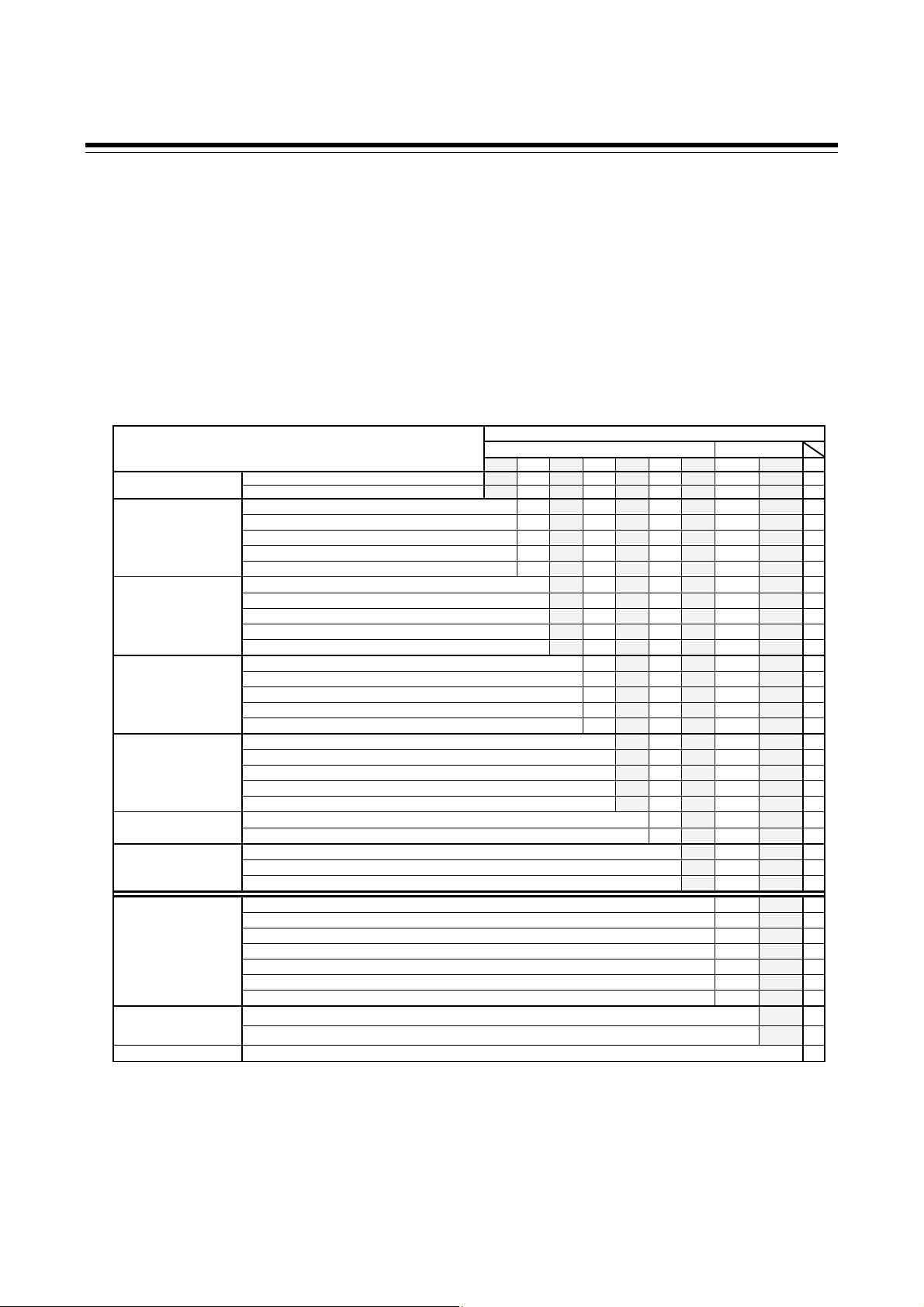
1.2.1 Z-TIO module
Name Q’TY Remarks
Z-TIO module 1
Z-TIO Instruction Manual
(IMS01T01-E)
Z-TIO Host Communication Quick Instruction Manual
(IMS01T02-E)
Joint connector cover KSRZ-517A 2 Enclosed with instrument
Power terminal cover KSRZ-518A 1 Enclosed with instrument
SRZ Instruction Manual
(IMS01T04-E)
1 Enclosed with instrument
1 Enclosed with instrument
1 This manual (sold separately) *
* This manual can be downloaded from our website:
URL: http://www.rkcinst.com/english/manual_load.htm
1.2.2 Z-DIO module
1. OUTLINE
Name Q’TY Remarks
Z-DIO module 1
Z-DIO module Instruction Manual
(IMS01T03-E)
Joint connector cover KSRZ-517A 2 Enclosed with instrument
Power terminal cover KSRZ-518A 1 Enclosed with instrument
SRZ Instruction Manual
(IMS01T04-E)
1 Enclosed with instrument
1 This manual (sold separately) *
* This manual can be downloaded from our website:
URL: http://www.rkcinst.com/english/manual_load.htm
1.2.3 Accessories (sold separately)
Name
End plate DEP-01 2
Connector SRZP-01 (front screw type) 2 For the connector type module
Connector SRZP-02 (side screw type) 2 For the connector type module
CT cable W-BW-03-1000 1 For CT input connector (cable length: 1 m)
CT cable W-BW-03-2000 1 For CT input connector (cable length: 2 m)
CT cable W-BW-03-3000 1 For CT input connector (cable length: 3 m)
Current transformer CTL-6-P-N 1 0.0 to 30.0 A
Current transformer CTL-12-S56-10L-N 1 0.0 to 100.0 A
Terminal cover KSRZ-510A 1 For the terminal type module
Q’TY
Remarks
IMS01T04-E1 1-3
Page 12
1. OUTLINE
1.3 Model Code
Check whether the delivered product is as specified by referring to the following model code list. If the
product is not identical to the specifications, please contact RKC sales office or the agent.
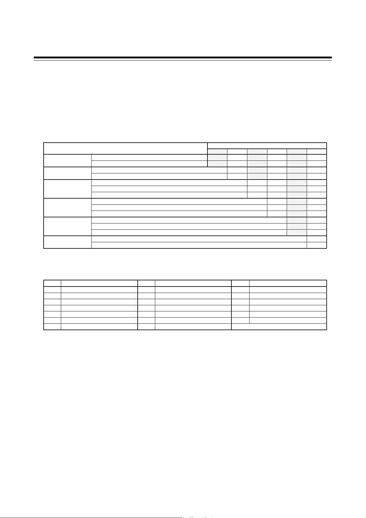
1.3.1 Z-TIO module
Suffix code
4-channel type:
Z-TIO-A − □ − □ □ □ □ / □ □ − □ □□□/Y
(1) (2) (3) (4) (5) (6) (7) (8) (9) (10)
2-channel type:
(1) (2) (3) (4) (5) (6) (7) (8) (9) (10)
Wiring type Terminal type T
Connector type C
Relay contact output M
Voltage pulse output V
Output1 (OUT1) Voltage output, Current output (See Output Code Table)
Triac output T
Open collector output D
Relay contact output M
Voltage pulse output V
Output2 (OUT2) Voltage output, Current output (See Output Code Table)
Triac output T
Open collector output D
Relay contact output M
Output3 (OUT3) Voltage pulse output V
[Z-TIO-A type only] Voltage output, Current output (See Output Code Table)
Triac output T
Open collector output D
Relay contact output M
Output4 (OUT4) Voltage pulse output V
[Z-TIO-A type only] Voltage output, Current output (See Output Code Table)
Triac output T
Open collector output D
input
No quick start code (Configured as factory default) N
Quick start code Specify quick start code 1 1
Specify quick start code 1 and 2 2
Control Method
(all channel common)
[Quick start code 1]
(all channel common)
[Quick start code 1]
Instrument specification Version symbol /Y
1
Z-TIO-A type: CH2 and CH4 are unused Z-TIO-B type: CH2 is unused
2
Z-TIO-A type: CH2 and CH4 are feedback resistance input (for monitor) Z-TIO-B type: CH2 is feedback resistance input (for monitor)
Specifications
None N Current transformer (CT)
CT (4 points) [4-channel type], CT (2 points) [2-channel type] A
No specify quick start code No code
PID action with AT (Reverse action) F
PID action with AT (Direct action) D
Heat/cool PID action with AT 1 G
Heat/cool PID action with AT (for Extruder [air cooling]) 1 A
Heat/cool PID action with AT (for Extruder [water cooling]) 1 W
Position proportioning PID action without FBR 2 Z
No specify quick start code No codeMeasured input and Range
See range code table.
Z-TIO-B − □ − □ □ / □ N □ − □ □□□/Y
(1) (2) (3) (6) (7) (8) (9) (10)
Suffix code
Hardware coding only Quick start code1
1-4 IMS01T04-E1
Page 13

Output Code Table
Voltage output (0 to 1 V DC) 3 Voltage output (1 to 5 V DC) 6
Voltage output (0 to 5 V DC) 4 Current output (0 to 20 mA DC) 7
Voltage output (0 to 10 V DC) 5 Current output (4 to 20 mA DC) 8
Range Code Table
[Thermocouple (TC) input, RTD input] [Voltage input, Current input]
Type Code Range (Input span) Code Range (Input span) Type Code Range (Input span)
K35 −200.0 to +400.0 °C KA1 0 to 800 °F 0 to 10 mV DC 101
K K40 −200.0 to +800.0 °C KA2 0 to 1600 °F 0 to 100 mV DC 201 Programmable range
K42 −200.0 to +1372.0 °C KC7 −328 to +2501 °F 0 to 1 V DC 301 −19999 to +19999
K09 0.0 to 400.0 °C KA4 0.0 to 800.0 °F 0 to 5 V DC 401 [The decimal point position is selectable]
K10 0.0 to 800.0 °C 0 to 10 V DC 501 (Factory set value: 0.0 to 100.0 %)
J27 −200.0 to +400.0 °C JA1 0 to 800 °F 1 to 5 V DC 601
J J32 −200.0 to +800.0 °C JA2 0 to 1600 °F 0 to 20 mA DC 701
J29 −200.0 to +1200.0 °C JB9 −328 to +2192 °F 4 to 20 mA DC 801
J08 0.0 to 400.0 °C JB6 0.0 to 800.0 °F
J09 0.0 to 800.0 °C
T T19 −200.0 to +400.0 °C TC5 −328 to +752 °F
TC6 0.0 to 752.0 °F
E E20 −200.0 to +1000.0 °C EB2 0.0 to 800.0 °F
EB1 −328 to +1832 °F
S S06 −50 to +1768 °C SA7 −58 to +3214 °F
R R07 −50 to +1768 °C RA7 −58 to +3214 °F
B B03 0 to 1800 °C BB1 32 to +3272 °F
N N07 −200 to +1372 °C NA8 −328 to +2502 °F
PLII A02 0 to 1390 °C AA2 0 to 2534 °F
W5Re/W26Re W03 0 to 2300 °C WB1 32 to 4208 °F
Pt100 D21 −200.0 to +200.0 °C DC6 −328.0 to +752.0 °F
D35 −200.0 to +850.0 °C DD2 328 to +1562 °F
JPt100 P31 −200.0 to +649.0 °C PC6 −328.0 to +752.0 °F
PD2 328 to +1200 °F
Output type Code Output type Code
1. OUTLINE
IMS01T04-E1
1-5
Page 14
1. OUTLINE
Quick start code 2 (Initial setting code)
Quick start code 2 tells the factory to ship with each parameter preset to the values detailed as specified by
the customer. Quick start code is not necessarily specified when ordering, unless the preset is requested.
These parameters are software selectable items and can be re-programmed in the field via the manual.
□ □ □ □-□ □
(1) (2) (3) (4) (5) (6)
Specifications
Event function 1 (EV1) 1 None N
Event function 1 (See Event type code table)
Event function 2 (EV2) 1 None N
Event function 2 (See Event type code table)
Event function 3 (EV3) 1 None N
Event function 3 (See Event type code table)
Temperature rise completion 6
Event function 4 (EV4) 1 None N
Event function 4 (See Event type code table)
Control loop break alarm (LBA) 5
None N
CT type 2 CTL-6-P-N P
CTL-12-S56-10L-N S
Communication protocol RKC communication (ANSI X3.28) 1
Modbus 2
1
If it is desired to specify the deviation action between channels or the deviation using local SV, the settings must be configured by the customer. (Engineering setting data)
2
The CT assignment and heater break alarm (HBA) type must be configured by the customer. (Engineering setting data)
Event type code table
Code Type Code Type Code Type
A Deviation high H Process high V SV high
B Deviation low J Process low W SV low
C Deviation high/low K Process high with hold action 1 MV high [heat-side]
D Band L Process low with hold action 2 MV low [heat-side]
E Deviation high with hold action Q Deviation high with re-hold action 3 MV high [cool-side]
F Deviation low with hold action R Deviation low with re-hold action 4 MV low [cool-side]
G Deviation high/low with hold action T Deviation high/low with re-hold action
Quick start code 2 (Initial setting code)
(1) (2) (3) (4) (5) (6)
1-6
IMS01T04-E1
Page 15
00
assignment
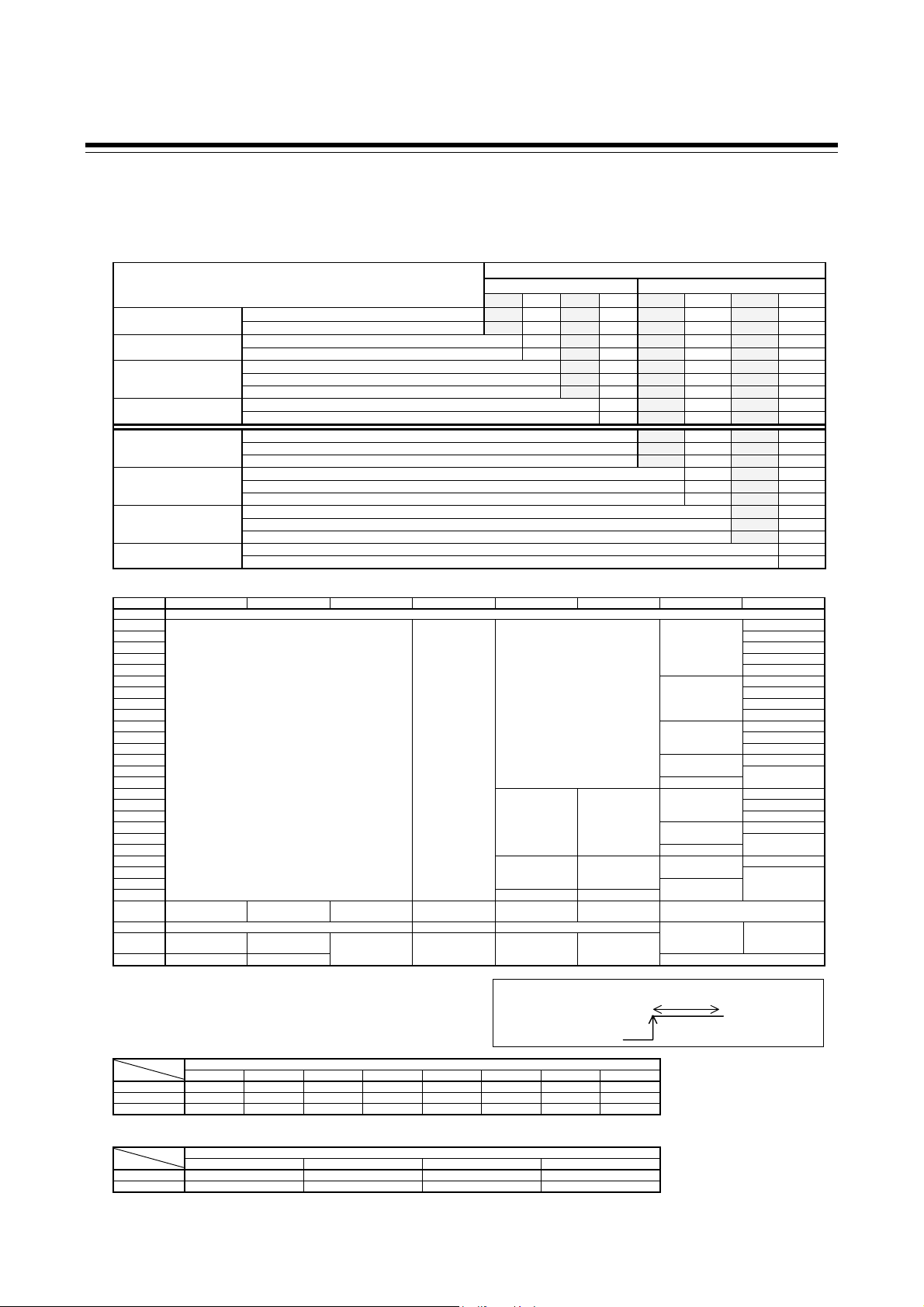
1.3.2 Z-DIO module
1. OUTLINE
Z-DIO-A
(1) (2) (3) (4) (5) (6) (7) (8)
− □ − □ □ / □ − □□□□
Suffix code
(1) (2) (3) (4) (5) (6) (7) (8)
Specifications
Wiring type Terminal type T
Connector type C
Digital input (DI) None N
8 points A
None N
Digital output (DO) Relay contact output (8 points) M
Open collector output (8 points) D
Quick start code No quick start code (Configured as factory default) N
(DI/DO assignments) Specify quick start code 1 1
DI signal assignments No specify quick start code No code
(DI1 to DI8) None N
[Quick start code 1] See DI assignment code table.
DO signal assignments No specify quick start code No code
(DO1 to DO4) None N
[Quick start code 1] See DO assignment code table.
DO signal assignments No specify quick start code No code
(DO5 to DO8) None N
[Quick start code 1] See DO assignment code table.
Communication protocol RKC communication (ANSI X3.28) 1
Modbus 2
Hardware coding only Quick start code1
DI assignment code table
Code DI1 DI2 DI3 DI4 DI5 DI6 DI7 DI8
No
01 AUTO/MAN
02 REM/LOC
03 Inte rlock re lease EDS start signal 1
04 Soak stop
05 RUN/STOP
06 REM/LOC
07 AUTO /MAN EDS start signal 1
08 Operation mode
09 RUN/STOP
10 EDS start signal 1
11 REM/LOC Soak stop
12 RUN/STOP
13 Area set 2 Soak stop
14
15 Soak stop
16 EDS start signal 1
17 REM/LOC Soak stop
18 Interlock release AUTO/MAN RUN/STOP
19 Soak stop
20
21 Soak stop
22 Soak stop
23 AUTO/MAN REM/LOC
24 RUN/STOP
25
26 Memory area
transfer (1, 2)
27 Memory area transfer (1 to 8) 1 Area set
28 Memory area
transfer (1, 2)
29 EDS start signal 1 EDS start signal 2
RUN/STOP: RUN/STOP transfer ( Contact closed: RUN)
AUTO/MAN: Auto/Manual transfer (Contact closed: Manual mode)
REM/LOC: Remote/Local transfer (Contact closed: Remote mode)
Interlock release (Contact closed: Interlock release)
EDS start signal 1 (Contact closed: EDS start signal ON [for disturbance 1])
EDS start signal 2 (Contact closed: EDS start signal ON [for disturbance 2])
Soak stop (Contact closed: Soak stop)
1
Memory area transfer (×:Contact open −: Contact closed)
DI1 × − × − × − × −
DI2 × × − − × × − −
DI3 × × × × − − − −
2
Area set becomes invalid prior to factory shipment.
3
Operation mode transfer (×:Contact open −: Contact closed)
DI5 (DI7) × − × −
DI6 (DI8) × × − −
Memory area transfer (1 to 8)
2
Interlock release RUN/STOP AUTO/MAN REM/LOC
Area set
1
2
Area set
1
1 2 3 4 5 6 7 8
Unused Monitor Monitor + Event function Cont rol
1
REM/L OC ED S start signal 1
2
Operation mode
Interlock release RUN/STOP AUTO/MAN REM/LOC
DI signal will become valid at rising edge after the closed contact is held for 250ms.
Contact closed
Contact open
Memory area number
Operation mode
3
Soak stop
EDS start signal 1
RUN/STOP
EDS start signal 1
EDS start signal 1
Soak stop
Operation mode
3
EDS start signal 1 EDS start signal 2
Operation mode 3
250 ms or more
(Rising edge)
RUN/STOP
3
Continued on the next page.
IMS01T04-E1
1-7
Page 16

1. OUTLINE
Continued from the previous page.
DO assignment code table
[DO1 to DO4]
Code DO1 DO2 DO3 DO4
00 No assignment
01
02 Event 1 comprehensive output 1 Event 2 comprehensive output 2 Event 3 comprehensive output 3 Event 4 comprehensive output 4
03 Event 1 (CH1) Event 2 (CH1) Event 3 (CH1) Event 4 (CH1)
04 Event 1 (CH2) Event 2 (CH2) Event 3 (CH2) Event 4 (CH2)
05 Event 1 (CH3) Event 2 (CH3) Event 3 (CH3) Event 4 (CH3)
06 Event 1 (CH4) Event 2 (CH4) Event 3 (CH4) Event 4 (CH4)
07 Event 1 (CH1) Event 1 (CH2) Event 1 (CH3) Event 1 (CH4)
08 Event 2 (CH1) Event 2 (CH2) Event 2 (CH3) Event 2 (CH4)
09 Event 3 (CH1) Event 3 (CH2) Event 3 (CH3) Event 3 (CH4)
10 Event 4 (CH1) Event 4 (CH2) Event 4 (CH3) Event 4 (CH4)
11 HBA (CH1) HBA (CH2) HBA (CH3) HBA (CH4)
12 Burnout status (CH1) Burnout status (CH2) Burnout status (CH3) Burnout status (CH4)
13 Temperature rise completion 5 HBA comprehensive output 6 Burnout state comprehensive output 7 DO4 manual output
1
Logical OR of Event 1 (ch1 to ch4)
2
Logical OR of Event 2 (ch1 to ch4)
3
Logical OR of Event 3 (ch1 to ch4)
4
Logical OR of Event 4 (ch1 to ch4)
5
Temperature rise completion status (ON when temperature rise completion occurs for all channels for which event 3 is set to temperature rise completion.)
6
Logical OR of HBA (ch1 to ch4)
7
Logical OR of burnout state (ch1 to ch4)
[DO5 to DO8]
Code DO5 DO6 DO7 DO8
00 No assignment
01
02 Event 1 comprehensive output 1 Event 2 comprehensive output 2 Event 3 comprehensive output 3 Event 4 comprehensive output 4
03 Event 1 (CH1) Event 2 (CH1) Event 3 (CH1) Event 4 (CH1)
04 Event 1 (CH2) Event 2 (CH2) Event 3 (CH2) Event 4 (CH2)
05 Event 1 (CH3) Event 2 (CH3) Event 3 (CH3) Event 4 (CH3)
06 Event 1 (CH4) Event 2 (CH4) Event 3 (CH4) Event 4 (CH4)
07 Event 1 (CH1) Event 1 (CH2) Event 1 (CH3) Event 1 (CH4)
08 Event 2 (CH1) Event 2 (CH2) Event 2 (CH3) Event 2 (CH4)
09 Event 3 (CH1) Event 3 (CH2) Event 3 (CH3) Event 3 (CH4)
10 Event 4 (CH1) Event 4 (CH2) Event 4 (CH3) Event 4 (CH4)
11 HBA (CH1) HBA (CH2) HBA (CH3) HBA (CH4)
12 Burnout status (CH1) Burnout status (CH2) Burnout status (CH3) Burnout status (CH4)
13 Temperature rise completion 5 HBA comprehensive output 6 Burnout state comprehensive output 7 DO8 manual output
1
Logical OR of Event 1 (ch1 to ch4)
2
Logical OR of Event 2 (ch1 to ch4)
3
Logical OR of Event 3 (ch1 to ch4)
4
Logical OR of Event 4 (ch1 to ch4)
5
Temperature rise completion status (ON when temperature rise completion occurs for all channels for which event 3 is set to temperature rise completion.)
6
Logical OR of HBA (ch1 to ch4)
7
Logical OR of burnout state (ch1 to ch4)
DO1 manual output DO2 manual output DO3 manual output DO4 manual output
DO5 manual output DO6 manual output DO7 manual output DO8 manual output
1-8
IMS01T04-E1
Page 17

A
A
1.4 Parts Description
1.4.1 Z-TIO module
Module mainframe
<Terminal type>
Loader
communication
connector
CT Input
connector
(Optional)
Input/output
terminals
<Connector type>
Loader
communication
connector
CT Input
connector
(Optional)
Input/output
connector
Indication lamps
FAIL/RUN [Green or Red] When normal (RUN): A green lamp is on
Self-diagnostic error (FAIL): A green lamp flashes
Instrument abnormality (FAIL): A red lamp is on
RX/TX [Green] During data send and receive: A green lamp turns on
Switches
Address setting switch
DIP switch
Input select switch
FAIL/ UNR
RX/TX
LOADER
A
9
8
7
6
CT4
TIO
CT3
C
D
B
E
F
0
1
2
3
4
5
CT1
CT2
Indication lamps
ddress setting
switch
Input
select switch
(for CH3)
Input
select switch
(for CH4)
(These diagrams represent any module of SRZ.)
FAIL/ UNR
RX/TX
B
A
LOADER
9
8
7
6
CT4
TIO
CT3
CN3
C
D
E
F
0
1
2
3
4
5
CT1
CT2
CN1
Indication lamps
ddress setting
switch
Input
select switch
(for CH3)
CN4
CN2
Input
select switch
(for CH4)
(These diagrams represent any module of SRZ.)
Sets the Z-TIO module address.
(See P. 5-2.)
Sets the communication speed, data bit configuration, and communication
protocol. (See P. 5-3.)
Selector switch for the measurement input type.
(See P. 8-70.)
1. OUTLINE
DIP switch
Module
mainframe
Input select
switch
(for CH1)
Base
Input select
switch
(for CH2)
DIP switch
Module
mainframe
Input select
switch
(for CH1)
Base
Input select
switch
(for CH2)
IMS01T04-E1 1-9
Page 18

1. OUTLINE
f
Base
Mounting holes (M3 screw)
Holes for screws to fix the base to
a panel, etc.
Customer must provide the M3 screws.
Mounting bracket
Used to fix the module on DIN rails and
also to fix each module joined together.
Joint connector
Used to mechanically and electrically connect
each module.
Power supply terminals
Supply power to only one of the joined
modules, and all of the joined modules will
receive power.
(See 4.1 Wiring Cautions)
Communication terminals (RS-485)
Connect communication wires to only one o
the joined modules, and all of the joined
modules will communicate.
1-10
IMS01T04-E1
Page 19

A
A
1.4.2 Z-DIO module
Module mainframe
<Terminal type>
Loader
communication
connector
Digital input
terminals
<Connector type>
Loader
communication
connector
Digital input
connector
IN OUT
IN OUT
CN3
CN4
LOADER
DIO
LOADER
DIO
FAIL/ UNR
RX/TX
FAIL/ UNR
RX/TX
1. OUTLINE
D
E
F
0
1
2
3
4
D
E
F
0
1
2
3
4
CN1
CN2
Indication lamps
ddress setting switch
Digital output
terminals
Indication lamps
ddress setting switch
Digital output
connector
DIP switch
Module
mainframe
Base
DIP switch
Module
mainframe
Base
C
B
A
9
8
7
6
5
C
B
A
9
8
7
6
5
Indication lamps
FAIL/RUN [Green or Red] When normal (RUN): A green lamp is on
Self-diagnostic error (FAIL): A green lamp flashes
Instrument abnormality (FAIL): A red lamp is on
RX/TX [Green] During data send and receive: A green lamp turns on
Switches
Address setting switch
DIP switch
Sets the Z-DIO module address.
(See P. 5-2.)
Sets the communication speed, data bit configuration, and communication
protocol. (See P. 5-3.)
Terminal configurations of the base are the same as the base of Z-TIO module. (See P. 1-10)
IMS01T04-E1
1-11
Page 20

MEMO
1-12
IMS01T04-E1
Page 21

HANDLING
PROCEDURE TO
OPERATION
1.1 ******** ..............................................................................................1-2
1.2 *******................................................................................................1-3
1.3 ****** .................................................................................................1-4
1.4 *********** ..........................................................................................1-5
1.4.1 ***** ...........................................................................................................1-6
1.4.2 ******** ....................................................................................................... 1-7
IMS01T04-E1 2-1
Page 22
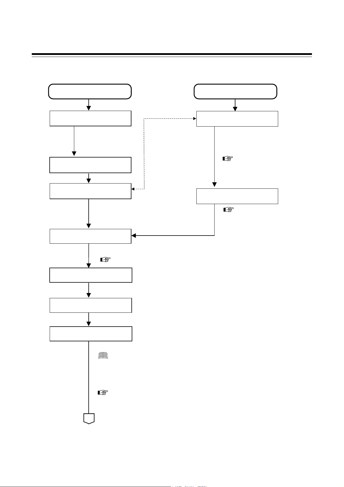
2. HANDLING PROCEDURE TO OPERATION
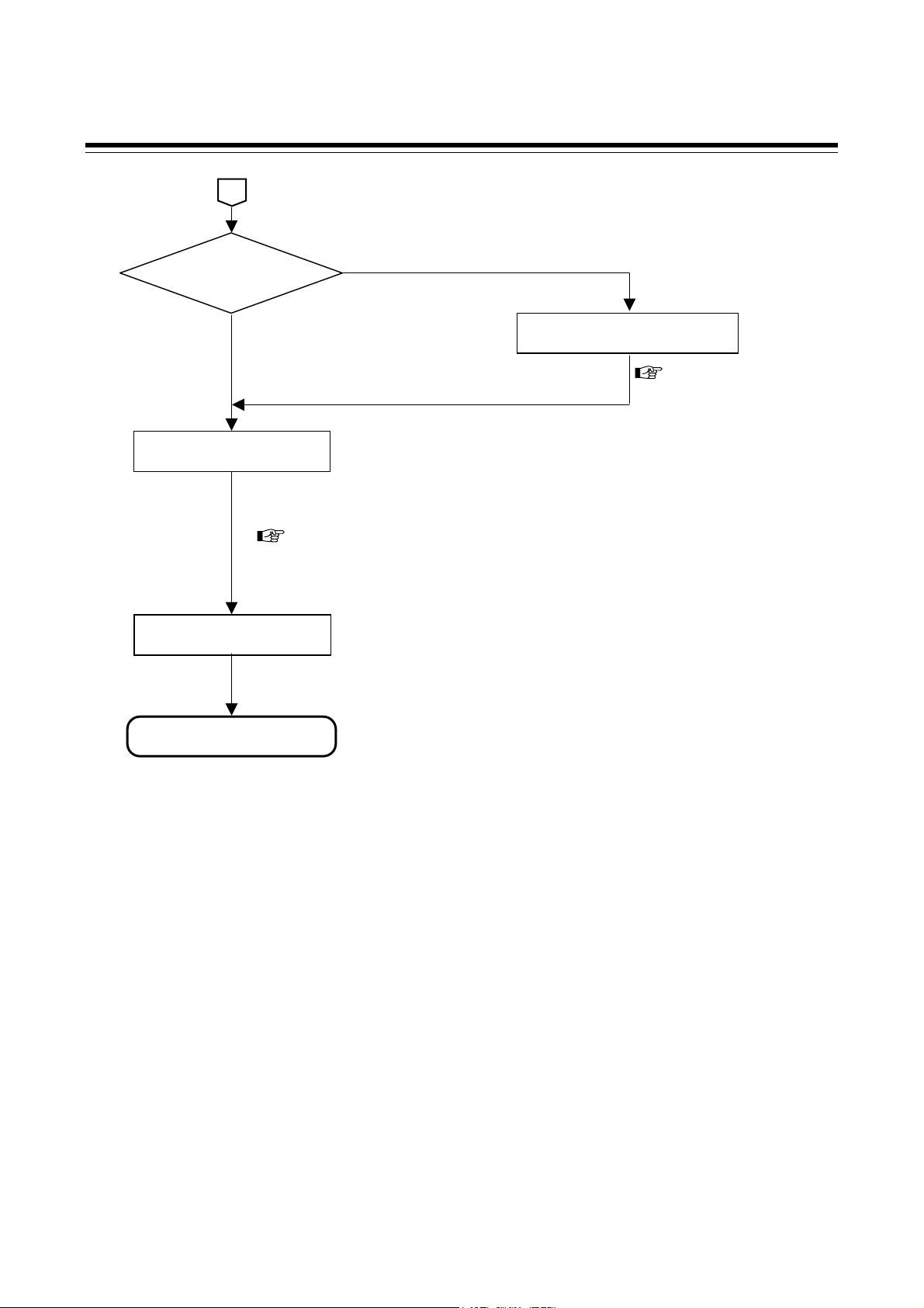
2. Handling Procedure to Operation
Conduct necessary setting before operation according to the procedure described below.
Processing of
the host computer side
Processing of the SRZ side
Preparation of
communication program
Execute it after turning
on a power supply of
the host computer.
Communication port setting
Set the host computer
and SRZ in always
the same value.
Setting of
communication relation
• Communication speed setting
Data bit configuration
•
•
Communication protocol selection
See 5.2 Protocol Selections and
Communication Speed Setting
(P. 5-3).
Setting of
communication relation
• Communication speed setting
•
Data bit configuration
Communication protocol selection
•
Module address setting
See 5.1 Module Address
Setting (P. 5-2).
Communication line connection
Execute it after turning off a power supply of the host computer.
See 4. WIRING (P. 4-1).
Power-ON
Turn on the power of the host computer and SRZ.
Communication program start
Engineering setting data
Setting of
Before setting operation data items, always set initial setting data items so as to satisfy
the specification used.
Set the Input scale high/low limit, Input range decimal point position, Control type,
Event type etc.
For engineering setting data items, see following pages.
• Z-TIO module: 8.2.2 Engineering setting data items (P. 8-61)
• Z-DIO module: 8.3.2 Engineering setting data items (P. 8-153)
A
2-2 IMS01T04-E1
Page 23
2. HANDLING PROCEDURE TO OPERATION
A
Control action type?
Position proportioning control
PID control or
Heat/cool PID control
Adjustment of the valve position
For details, see P. 8-118.
Setting of
Normal setting data
Set parameters in Normal setting of data.
For normal setting data items, see following pages.
• Z-TIO module: 8.2.1 Normal setting data items (P. 8-3)
• Z-DIO module: 8.3.1 Normal setting data items (P. 8-143)
Control RUN
Set the control RUN/STOP transfer to the “RUN.”
Operation start
IMS01T04-E1
2-3
Page 24

MEMO
2-4 IMS01T04-E1
Page 25

MOUNTING
3.1 Mounting Cautions ...........................................................................3-2
3.2 Dimensions.......................................................................................3-3
3.3 DIN Rail Mounting ............................................................................3-4
3.4 Panel Mounting ................................................................................3-6
3.5 Joining Each Module ........................................................................3-7
IMS01T04-E1 3-1
Page 26

3. MOUNTING
3.1 Mounting Cautions
This chapter describes installation environment, mounting cautions, dimensions and mounting procedures.
To prevent electric shock or instrument failure, always turn off the power before
mounting or removing the instrument.
(1) This instrument is intended to be used under the following environmental conditions.
(IEC61010-1) [OVERVOLTAGE CATEGORY II, POLLUTION DEGREE 2]
(2) Use this instrument within the following environment conditions.
• Allowable ambient temperature: −10 to +50 °C
• Allowable ambient humidity: 5 to 95 % RH
(Absolute humidity: MAX.W.C 29 g/m
• Installation environment conditions: Indoor use
Altitude up to 2000 m
WARNING
!
3
dry air at 101.3 kPa)
(3) Avoid the following conditions when selecting the mounting location:
• Rapid changes in ambient temperature which may cause condensation.
• Corrosive or inflammable gases.
• Direct vibration or shock to the mainframe.
• Water, oil, chemicals, vapor or steam splashes.
• Excessive dust, salt or iron particles.
• Excessive induction noise, static electricity, magnetic fields or noise.
• Direct air flow from an air conditioner.
• Exposure to direct sunlight.
• Excessive heat accumulation.
(4) Take the following points into consideration when mounting this instrument in the panel.
• Provide adequate ventilation space so that heat does not build up.
• Do not mount this instrument directly above equipment that generates large amount of heat (heaters,
transformers, semi-conductor functional devices, large-wattage resistors).
• If the ambient temperature rises above 50 °C, cool this instrument with a forced air fan, cooler, or the like.
However, do not allow cooled air to blow this instrument directly.
• In order to improve safety and the immunity to withstand noise, mount this instrument as far away as
possible from high voltage equipment, power lines, and rotating machinery.
− High voltage equipment: Do not mount within the same panel.
− Power lines: Separate at least 200 mm
− Rotating machinery: Separate as far as possible
• Mount this instrument in the horizontal direction for panel. If you did installation except a horizontal
direction, this causes malfunction.
3-2 IMS01T04-E1
Page 27

3.2 Dimensions
[Terminal type] [Connector type]
3. MOUNTING
(Unit: mm)
85
100
5
100
5
76.9 2.9 30 6.7
Space required between each module vertically
When the module is mounted on the panel, allow a minimum of 50 mm at the top and bottom of the module
to attach the module to the mainframe.
50 mm or more
Depth for connector mount type module (Connector type)
Space for connectors and cables must be considered when installing.
IMS01T04-E1 3-3
76.9 mm Approx. 50 mm
Connector
(Plug)
Page 28
3. MOUNTING
3.3 DIN Rail Mounting
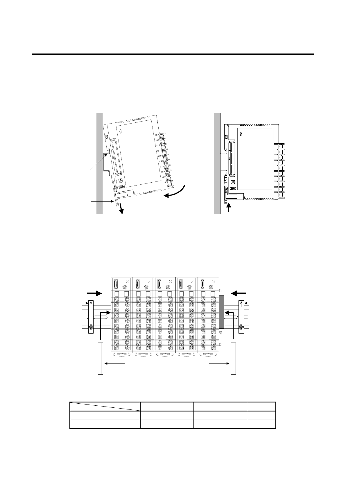
Mounting procedures
1. Pull down the mounting bracket at the bottom of the module (A). Attach the hooks on the top of the
module to the DIN rail and push the lower section into place on the DIN rail (B).
2. Slide the mounting bracket up to secure the module to the DIN rail (C).
DIN rail
Mounting
bracket
(A) Pull down
(B)
Push
Mounting End Plates
To firmly fix the modules, use end plates on both sides of the mounted modules.
End plate
(sold separately)
* It is recommended to use a plastic cover on the connector on both sides of the mounted
modules for protection of connectors.
End plate
Joint connector cover
Joint connector cover
*
(Standard equipment)
Parts code Ordering code Q’ty
DEP-01 00434944 2
KSRZ-517A 00433384 2
End plate
(sold separately)
(C) Locked
3-4 IMS01T04-E1
Page 29
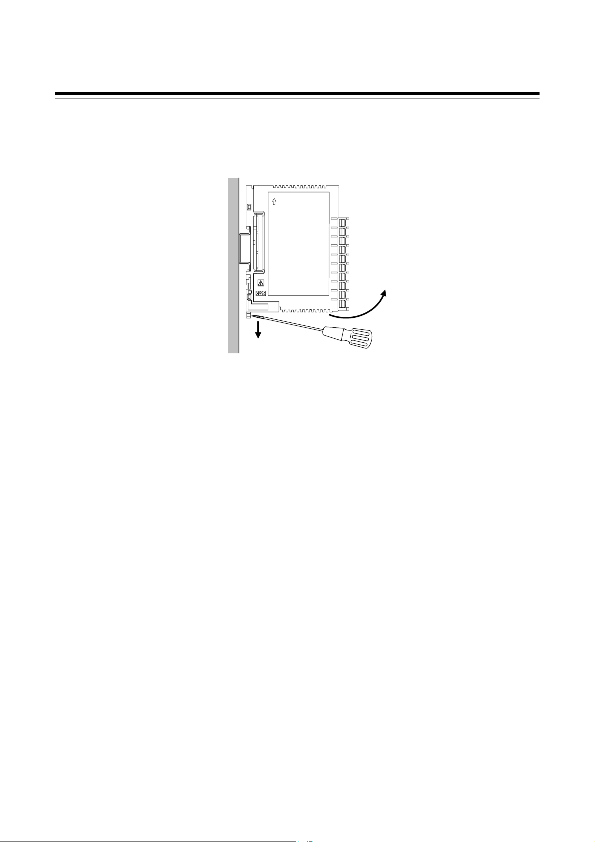
Removing procedures
1. Pull down a mounting bracket with a blade screwdriver (A).
2. Lift the module from bottom, and take it off (B).
(A) Pull down
3. MOUNTING
(B) Lift and take off
IMS01T04-E1
3-5
Page 30
3. MOUNTING
3.4 Panel Mounting
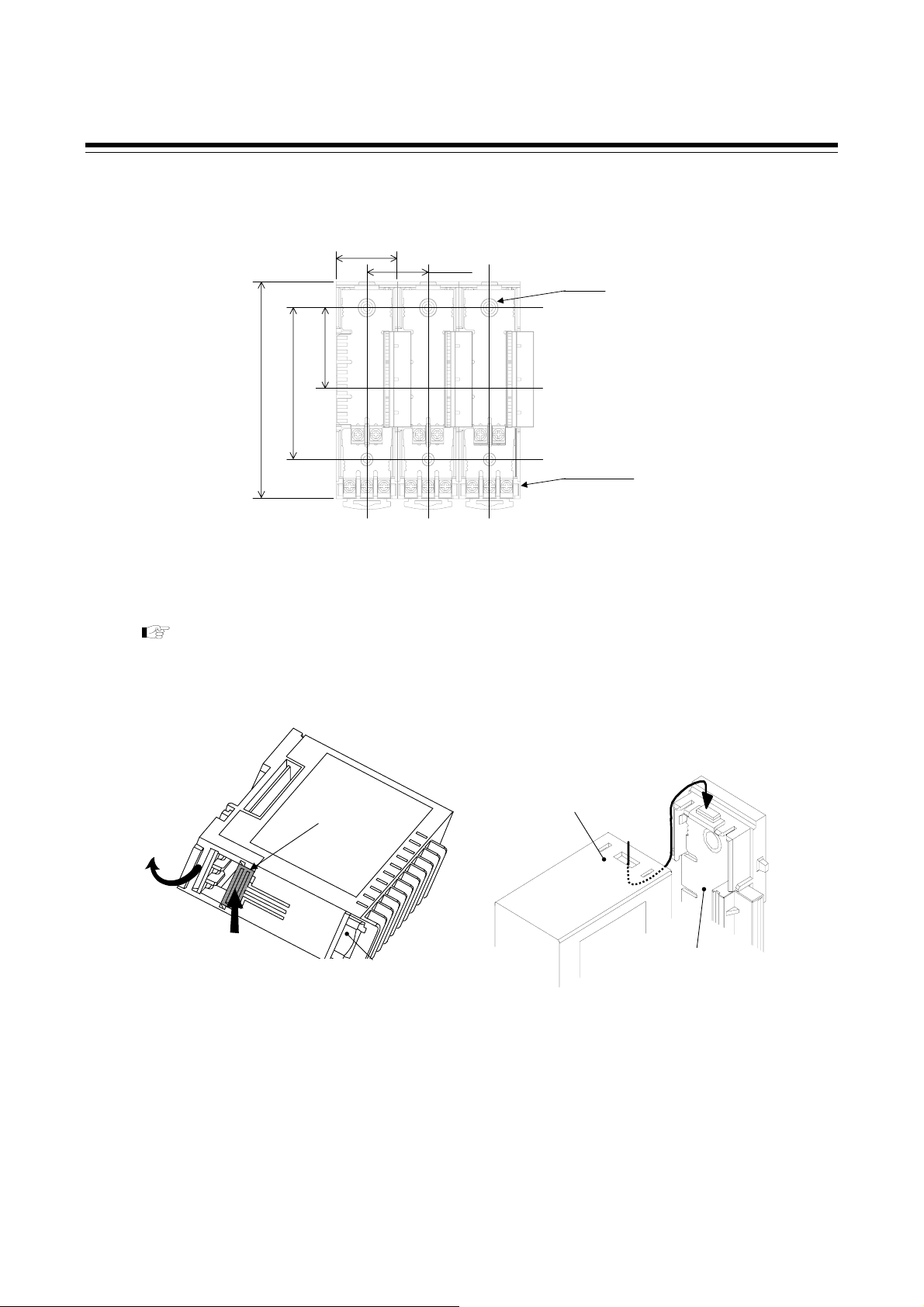
Mounting procedures
1. Refer to the mounting dimensions below when selecting the location.
(30)
(Unit: mm)
30±0.2
M3
Recommended screw:
M3 × 10
38
Recommended
tightening torque:
100
70±0.2
0.3 N・m (3 kgf・cm)
Base
Mounting dimensions
2. Remove the base from the module (B) while the lock is pressed (A). (Fig.1)
3. Join bases. Then, lock them by pushing in the mounting brackets.
See the 3.5 Joining Each Module (P.3-7).
4. Fix the base to its mounting position using M3 screws. Customer must provide the screws.
5. Mount the module on the base. (Fig.2)
Lock
(Top of the module mainframe)
(B)
(A)
(Bottom of the module mainframe)
Fig.1: Removing the base
Fig 2: Mounting the module mainframe
(Base)
3-6 IMS01T04-E1
Page 31

3. MOUNTING
r
3.5 Joining Each Module
Joining procedures
1. Mount the modules on the DIN rail.
2. Slide the modules until the modules are closely joined together and the joint connectors are securely
connected.
3. Push in the mounting brackets to lock the modules together and fix to the DIN rail.
For panel mounting, mount the module mainframes after the bases are joined and mounted.
(Front view of module mainframe)
(Rear view of base)
State where
each module is
locked.
Mounting
bracket
Joint connecto
Push in all of the mounting brackets.
Number of connected modules
The number of function modules (Z-TIO, Z-DIO) that can be connected at a time is indicated below.
• When connecting only function modules of the same type: 16 modules maximum
[Example] When connecting only Z-TIO modules
SRZ unit
Up to 16 modules
Z-TIO modules
• When connecting two or more different types of function modules: Up to 31 modules on entire SRZ unit
(However, the number of connected function modules of the same type must not exceed the maximum)
[Example] When connecting Z-TIO modules and Z-DIO modules
SRZ unit
Up to 31 modules on entire SRZ unit
Z-TIO module: 16 modules
Z-DIO module: 15 modules
IMS01T04-E1 3-7
Page 32

MEMO
3-8 IMS01T04-E1
Page 33

WIRING
4.1 Wiring Cautions................................................................................4-2
4.2 Connecting Precautions...................................................................4-4
4.3 Terminal Configuration .....................................................................4-5
4.3.1 Z-TIO module ............................................................................................4-5
4.3.2 Z-DIO module ............................................................................................ 4-9
4.4 Wiring Configuration.......................................................................4-11
4.5 Connection to Host Computer ........................................................4-13
4.6 Installation of Termination Resistor ................................................4-16
4.7 Connections for Loader Communication ........................................4-18
IMS01T04-E1 4-1
Page 34

4. WIRING
4.1 Wiring Cautions
This chapter describes wiring cautions, wiring layout and wiring of terminals.
To prevent electric shock or instrument failure, do not turn on the power until all
the wiring is completed.
• For thermocouple input, use the appropriate compensation wire.
• For RTD input, use low resistance lead wire with no difference in resistance between the three lead wires
(3-wire system).
• To avoid noise induction, keep input/output signal wires away from instrument power line, load lines and
power lines of other electric equipment.
• If there is electrical noise in the vicinity of the instrument that could affect operation, use a noise filter.
− Shorten the distance between the twisted power supply wire pitches to achieve the most effective noise
reduction.
− Always install the noise filter on a grounded panel. Minimize the wiring distance between the noise
filter output and the instrument power supply terminals to achieve the most effective noise reduction.
− Do not connect fuses or switches to the noise filter output wiring as this will reduce the effectiveness
of the noise filter.
• About eight seconds are required as preparation time for contact output every time the instrument is
turned on. Use a delay relay when the output line is used for an external interlock circuit.
• Power supply wiring must be twisted and have a low voltage drop.
• For an instrument with 24 V power supply, supply power from a SELV circuit.
• A suitable power supply should be considered in the end-use equipment. The power supply must be in
compliance with a limited-energy circuits (maximum available current of 8 A).
• Supply the power to only one of the joined modules. When power is supplied to any one of the joined
modules, all of the joined modules will receive power.
• Select the power capacity which is appropriate for the total power consumption of all joined modules and
the initial current surge when the power is turned on.
Power consumption (at maximum load): 140 mA max. (at 24 V DC) [Z-TIO module (4CH type)]
80 mA max. (at 24 V DC) [Z-TIO module (2CH type)]
70 mA max. (at 24 V DC) [Z-DIO module]
Rush current: 10 A or less
WARNING
!
4-2 IMS01T04-E1
Page 35

4. WIRING
For the terminal type module, use the solderless terminal appropriate to the screw size (M3).
Screw Size: M3 × 7 (with 5.8 × 5.8 square washer)
φ 5.9 MAX
Recommended tightening torque:
0.4 N・m (4 kgf・cm)
Applicable wire: Solid/twisted wire of 2 mm
2
φ 3.2 MIN
Recommended solderless terminals:
Manufactured by J.S.T MFG CO., LTD.
Circular terminal with isolation V1.25−MS3
5.6 mm
(M3 screw, width 5.5 mm, hole diameter 3.2 mm)
For the connector type module, use the following our connector (plug) [sold separately].
Connector type: SRZP-01 (Front-screw type)
SRZP-02 (Side-screw type)
Screw size: M2.5
Recommended tightening torque:
0.43 to 0.50 N・m (4.3 to 5.0 kgf・cm)
Used cable specifications:
Lead wire type:
Solid (AWG 28 [cross-section: 0.081 mm
Twisted wire (AWG 30 [cross-section: 0.051 mm
2
] to 12 [cross-section: 3.309 mm2]) or
2
] to 12 [cross-section: 3.309 mm2])
Stripping length: 9 to 10 mm (SRZP-01), 7 to 8 mm (SRZP-02)
9 to 10 mm
7 to 8 mm
(SRZP-01)
(SRZP-02)
IMS01T04-E1
4-3
Page 36

4. WIRING
4.2 Connecting Precautions
To prevent electric shock or instrument failure, turn off the power before
connecting or disconnecting the instrument and peripheral equipment.
• Connect connectors correctly in the right position. If it is forcibly pushed in with pins in the wrong
positions, the pins may be bent resulting in instrument failure.
• When connecting or disconnecting the connectors, do not force it too far to right and left or up and down,
but move it on the straight. Otherwise, the connector pins may be bent, causing instrument failure.
• When disconnecting a connector, hold it by the connector itself. Disconnecting connectors by yanking on
their cables can cause breakdowns.
WARNING
!
• To prevent malfunction, never touch the contact section of a connector with bare hands or with hands
soiled with oil or the like.
• To prevent damage to cables, do not bend cables over with excessive force.
4-4 IMS01T04-E1
Page 37

−
+
+
−
p
−
+
−
+
−
+
+IN−
+
−
p
+
−
p
+
−
+
−
4.3 Terminal Configuration
4.3.1 Z-TIO module
Input/output terminals
<Terminal type module>
<Common to both 2CH/4CH types>
Open collector
output
OUT1
11
12
Triac output
OUT1
Triac
11
12
Voltag e/Curr ent
input
14
IN
15
Current/Voltage
Voltage pulse/
ut
out
OUT1
11
12
RTD input
A
13
RTD
B
14
B
15
Relay contact
output
OUT1
NO
11
12
Thermocouple
input
14
TC
15
4. WIRING
CH1
Open collector
output
OUT2
16
17
Feedback
resistance input
O
18
W
19
C
20
Triac output
OUT2
Triac
16
17
Voltag e/Curr ent
input
19
20
Voltage pulse/
Current/Voltage
output
OUT2
RTD input
A
RTD
B
B
16
17
18
19
20
Relay contact
output
OUT2
NO
16
17
Thermocouple
input
19
TC
20
CH2
CH3
Open collector
output
OUT3
Feedback
resistance input
C
W
O
CH4
Isolated between each input channel
Voltage pulse output, Current output and Voltage output: Not isolated between output and power supply
Open collector
output
OUT4
<4-channel type only>
Voltage/Current
input
−
21
IN
+
22
Triac output
OUT3
input
26
IN
27
Triac output
OUT4
24
25
29
30
24
25
26
27
28
29
30
Triac
Voltage/Current
−
+
Triac
RTD input
B
21
B
22
RTD
A
23
Voltage pulse/
Current/Voltage
out
ut
OUT3
24
25
RTD input
B
26
B
27
RTD
A
28
Voltage pulse/
Current/Voltage
ut
out
OUT4
29
30
Thermocouple
input
21
TC
22
Relay contact
output
OUT3
input
output
OUT4
TC
24
25
26
27
29
30
NO
Thermocouple
Relay contact
NO
IMS01T04-E1 4-5
Page 38

4. WIRING
−
+
+
−
p
−
+
p
−
+
−
+
+IN−
+
−
p
+
−
p
+
−
+
−
<Connecter type module>
CH3
Open collector
OUT3
Feedback
resistance input
C
W
O
CH4
Open collector
OUT4
Isolated between each input channel
Voltage pulse output, Current output and Voltage output: Not isolated between output and power supply
output
output
Open collector
Open collector
resistance input
<4-channel type only>
Voltage/Current
input
−
1
IN
+
2
Triac output
OUT3
input
−
1
IN
+
2
Triac output
OUT4
4
5
4
5
4
5
1
2
3
4
5
Triac
Voltage/Current
Triac
<Common to both 2-Ch/4-Ch types>
2
1
2
1
TC
TC
5
4
5
4
1
2
4
5
1
2
4
5
Voltage pulse/
Current/Voltage
out
ut
OUT1
5
4
RTD input
A
3
RTD
B
2
B
1
Voltage pulse/
Current/Voltage
out
ut
OUT2
5
4
RTD input
A
3
RTD
B
2
B
1
output
OUT1
output
OUT2
Feedback
O
3
W
2
C
1
RTD input
B
B
RTD
A
Voltage pulse/
Current/Voltage
out
OUT3
RTD input
B
B
RTD
A
Voltage pulse/
Current/Voltage
out
OUT4
5
4
5
4
1
2
3
ut
4
5
1
2
3
ut
4
5
Triac output
OUT1
Triac
Voltag e/Curr ent
input
IN
Triac output
OUT2
Triac
Voltag e/Curr ent
input
Thermocouple
input
Relay contact
output
OUT3
NO
Thermocouple
input
Relay contact
output
OUT4
NO
Relay contact
output
OUT1
input
TC
output
OUT2
input
TC
5
4
2
1
5
4
2
1
NO
Thermocouple
Relay contact
NO
Thermocouple
CH1
CH2
4-6
IMS01T04-E1
Page 39

Input/output configurations by control specifications
2-channel
type
module
4-channel
type
module
Position proportioning control
Position proportioning control
PID control
Heat/Cool control
Position proportioning control
PID control
Heat/Cool control
Position proportioning control
PID control +
Heat/Cool control
PID control + Position
proportioning control
Heat/Cool control +
PID control
Heat/Cool control +
Position proportioning control
+ PID control
+ Heat/Cool control
Control type
"CH" numbers in parentheses indicate the control channel number of the module.
CH1 output
terminal (OUT1)
Control output
(CH1)
Heat-side output
(CH1)
Open-side output
(CH1)
Control output
(CH1)
Heat-side output
(CH1)
Open-side output
(CH1)
Control output
(CH1)
Control output
(CH1)
Heat-side output
(CH1)
Heat-side output
(CH1)
Open-side output
(CH1)
Open-side output
(CH1)
terminal (OUT2)
Control output
Cool-side output
Close-side output
Control output
Cool-side output
Close-side output
Control output
Control output
Cool-side output
Cool-side output
Close-side output
Close-side output
CH1 output
terminal (OUT1)
CH3 output
terminal (OUT3)
CH2 output
terminal (OUT2)
CH3 output
terminal (OUT3)
CH4 output
terminal (OUT4)
CH4 output
terminal (OUT4)
CH2 output
(CH2)
(CH1)
(CH1)
(CH2)
(CH1)
(CH1)
(CH2)
(CH2)
(CH1)
(CH1)
(CH1)
(CH1)
CH3 output
terminal (OUT3)
Control output
(CH3)
Heat-side output
(CH3)
Open-side output
(CH3)
Heat-side output
(CH3)
Open-side output
(CH3)
Control output
(CH3)
Open-side output
(CH3)
Control output
(CH3)
Heat-side output
(CH3)
CH1 output
terminal (OUT1)
CH2 output
terminal (OUT2)
4. WIRING
CH4 output
terminal (OUT4)
Control output
(CH4)
Cool-side output
(CH3)
Close-side output
(CH3)
Cool-side output
(CH3)
Close-side output
(CH3)
Control output
(CH4)
Close-side output
(CH3)
Control output
(CH4)
Cool-side output
(CH3)
IMS01T04-E1
4-7
Page 40

4. WIRING
Power supply terminals, Communication terminals
(Common to both terminal and connector type module)
2 1
Power supply terminals
3 4 5
1
2
CT input connector (Optional)
Pin No. Description
2 1
1
2
3
4
CT4 (CH4)
CT3 (CH3)
For the CT input, use the following our CT cable (with socket) and current transformer (CT).
[sold separately]
Cable type: W-BW-03- (: Standard cable length [unit: mm])
1000: 1m, 2000: 2 m, 3000: 3 m
4 3
[Sleeve color]
White: CT2 (Pin No. 1, 2), CT4 (Pin No. 1, 2)
Blue: CT1 (Pin No. 3, 4), CT3 (Pin No. 3, 4)
Description
24 V DC (+)
24 V DC (−)
Communication terminals (RS-485)
Terminal No.
3
4
5
Pin No. Description
34
12
1
2
3
4
Description
T/R (A)
T/R (B)
SG
CT2 (CH2)
CT1 (CH1)
4-8
Current transformer (CT): CTL-6-P-N (0.0 to 30.0 A) or CTL-12-S56-10L-N (0.0 to 100.0 A)
IMS01T04-E1
Page 41

p
−
−
+
−
− +
4.3.2 Z-DIO module
Digital input (DI1 to DI8)
<Terminal type module> <Connecter type module>
Voltage
contact in
DI4
DI3
DI2
DI1
COM
DI8
DI7
DI6
DI5
COM
21
22
23
24
25
26
27
28
29
30
ut
Voltage
*
contact input
CN3
Pin No. Description
1 DI4
2 DI3
3 DI2
4 DI1
5 COM
CN4
Pin No. Description
1 DI8
2 DI7
3 DI6
4 DI5
5 COM
4. WIRING
*
* An external power supply of 24 V DC is required for the voltage contact input.
Voltage contact input
24 V DC
DI1
DI4
DI5
DI8
COM
−
+
COM
Circuit configuration of digital input
IMS01T04-E1
4-9
Page 42

4. WIRING
−
+
Digital output (DO1 to DO8)
<Terminal type module> <Connecter type module>
Relay
contact output
COM
NO
DO1
NO
DO2
NO
DO3
NO
DO4
Open collector
output
11
12
13
14
15
COM
DO1
DO2
DO3
DO4
*
11
12
13
14
15
Relay contact output/
Open collector output
CN1
Pin No. Description
5 COM
4 DO1
3 DO2
2 DO3
1 DO4
*
COM
DO5
DO6
DO7
DO8
16
17
18
19
20
DO5
DO6
DO7
DO8
COM
NO
NO
NO
NO
16
17
18
19
20
* An external power supply of 12 to 24 V DC is required for the open collector output.
Relay contact output Open collector output
Load
DO1
DO4
DO5
Load
COM
Load
DO1
DO4
DO5
CN2
Pin No. Description
5 COM
4 DO5
3 DO6
2 DO7
1 DO8
Load
Load
COM
Load
DO8
Load
12 to 24 V DC
COM
DO8
Load
COM
Circuit configuration of digital output
Power supply terminals, Communication terminals
(Common to both terminal and connector type module)
Terminal configurations of the base are the same as the base of Z-TIO module. (See P.4-8)
4-10
IMS01T04-E1
Page 43

(
)
r
(
)
4.4 Wiring Configuration
To prevent electric shock or instrument failure, turn off the power before
connecting or disconnecting the instrument and peripheral equipment.
WARNING
!
When two or more Z-TIO module are connected
4. WIRING
Module address
(Slave address)
Module type controller SRZ
slave
1 2
0
Z-TIO module
15
Host
computer
(master)
RS-485
Internal communication line
(RS-485)
Termination resisto
Up to 16 Z-TIO modules can be connected.
When two or more Z-DIO module are connected to Z-TIO modules
Module address
(Slave address)
Host
computer
(master)
RS-485
0
1 2
Z-TIO module Z-DIO module
Up to 16 Z-DIO modules can be connected.
The maximum number of SRZ modules (including other function modules) on the same
communication line is 31.
Function modules (Z-TIO, Z-DIO) connected inside the same unit can be placed in any
position.
For the procedure for connecting modules, see 3.5 Joining Each Module (P. 3-7).
For the module address settings, see 5. Settings Before Operation (P. 5-1).
Module type controller SRZ
slave
15 3016 17 18
Internal communication line(RS-485)
Termination resistor
IMS01T04-E1 4-11
Page 44

4. WIRING
(
(
(
)
When two or more SRZ units are connected
Module address
(Slave address)
0
Host
computer
(master)
RS-485
Module type controller SRZ
1 2 3 4 5
Z-TIO module Z-DIO module
Internal communication line
Module address
(Slave address)
6
Module type controller SRZ
7 8 9 10 11
Z-TIO module
16 17 18
RS-485)
19 20 21
Z-DIO module
RS-485
Internal communication line
RS-485)
Module address
(Slave address)
Module type controller SRZ
12
13 14 15 22 23
Z-TIO module
Z-DIO module
RS-485
Internal communication
RS-485
line
Termination resistor
“SRZ unit” refers to a unit consisting of only Z-TIO modules, or a unit in which Z-TIO modules
are connected to several other function modules (Z-DIO).
Regardless of the number of units, a maximum of 16 SRZ Z-TIO modules and a maximum of 16
SRZ Z-DIO modules can be connected respectively. However, the maximum number of SRZ
modules that can be connected overall, including other function modules (Z-DIO), is 31.
Function modules (Z-TIO, Z-DIO) connected inside the same unit can be placed in any
position.
4-12
IMS01T04-E1
Page 45

4.5 Connection to Host Computer
Terminal number and signal details
4. WIRING
(Base)
3 4 5
Terminal No. Signal name Symbol
3 Send data/Receive data T/R (B)
4 Send data/Receive data T/R (A)
5 Signal ground SG
Wiring figure
Connection to the RS-485 port of the host computer (master)
Module type controller SRZ
Z-TIO module
(Slave)
SG
3
4
5
Connected by
T/R (A)
T/R (B)
RS-485
Pair wire
Shielded twisted
pair wire
the internal
communication line
SG
3
R
4
R: Termination resistor (Example: 120 Ω 1/2 W)
5
T/R (A)
T/R (B)
Z-TIO module
(Slave)
Up to 16 Z-TIO modules can be connected.
The maximum number of SRZ modules (including other function modules) on the same communication line is 31.
Host computer (Master)
T/R (A)
T/R (B)
R
SG
The cable must be provided by the customer.
The above figure shows an example of connecting of Z-TIO modules. However, this figure is
also used even when the Z-DIO module is connected instead of the Z-TIO module.
For installation method of termination resistor of the SRZ side, see 4.6 Installation of
Termination Resistor (P. 4-16).
IMS01T04-E1 4-13
Page 46

4. WIRING
Connection to the RS-232C port of the host computer (master)
A RS-232C/RS-485 converter is required.
Module type controller SRZ
Z-TIO module
(Slave)
RS-485
T/R (A) 3
Pair wire
Host computer (Master)
T/R (B)
SG
4
5
Shielded twisted
pair wire
T/R (A)
T/R (B)
R
SG
Connected by
the internal
RS-232C/RS-485 converter
communication line
SG
3
R
4
R: Termination resistor (Example: 120 Ω 1/2 W)
5
T/R (A)
T/R (B)
Z-TIO module
(Slave)
Up to 16 Z-TIO modules can be connected.
The maximum number of SRZ modules (including other function modules) on the same communication line is 31.
When the host computer (master) uses Windows95/98/Me/NT/2000/XP, use a
RS-232C/RS-485 converter with an automatic send/receive transfer function.
Recommended RS-232C/RS-485 converter:
CD485, CD485/Vmanufactured by Data Link, Inc. or equivalent
RS-232C
4-14
The cable must be provided by the customer.
The above figure shows an example of connecting of Z-TIO modules. However, this figure is
also used even when the Z-DIO module is connected instead of the Z-TIO module.
For installation method of termination resistor of the SRZ side, see
Termination Resistor (P. 4-16)
.
4.6 Installation of
IMS01T04-E1
Page 47

4. WIRING
Connection to the USB of the host computer (master)
When the host computer (OS: Windows 98SE/2000/XP) is corresponding to the USB connector, our
communication converter COM-K (sold separately) can be used.
Module type controller SRZ
Z-TIO module
(Slave)
RS-485
T/R (A)
T/R (B)
3
4
SG 5
Shielded twisted
pair wire
Connected by
the internal
communication line
T/R (A)
T/R (B)
Z-TIO module
(Slave)
Up to 16 Z-TIO modules can be connected.
The maximum number of SRZ modules (including other function modules) on the same communication line is 31.
SG 5
3
4
R
R: Termination resistor
(Example: 120 Ω 1/2 W)
Host computer (Master)
Pair wire
1
2
3
4
5
USB communication
converter COM-K *
* The termination resistor is built in to
the COM-K.
SG
T/R (A)
T/R(B)
Unused
Connected to USB port
of a personal computer
Connected to
USB connector
USB cable
(COM-K
accessory)
For the COM-K, see
COM-K Instruction Manual (IMR01Z01-E).
The cable must be provided by the customer.
The above figure shows an example of connecting of Z-TIO modules. However, this figure is
also used even when the Z-DIO module is connected instead of the Z-TIO module.
For installation method of termination resistor of the SRZ side, see
Termination Resistor (P. 4-16)
.
4.6 Installation of
IMS01T04-E1
4-15
Page 48

4. WIRING
(
)
r
4.6 Installation of Termination Resistor
When connecting termination resistors to each end of the RS-485 communication line, follow the procedure
below to connect the resistor to the SRZ end.
For the termination resistor on the host computer side, connect it so as to satisfy the host
computer used.
Mounting position
Connect a termination resistor between the communication terminals (No.3 and 4) of the module at the end
of the communication line from the host computer.
Termination resistor
(Example: 120
Ω 1/2 W)
T/R(A) T/R(B)
When two or more Z-TIO module are connected
Module type controller SRZ
Host
computer
(master)
RS-485
Z-TIO module
Internal communication line
(RS-485)
When two or more Z-DIO module are connected to Z-TIO module
Z-TIO module
Host
computer
(master)
RS-485
(Base)
34 5
Recommended tightening torque:
0.4 N
SG
To host computer
slave
Termination resisto
Module type controller SRZ
(slave)
Internal communication line (RS-485)
・m (4 kgf・cm)
Connect the termination
resistor to this module.
Connect the termination
resistor to this module.
Z-DIO module
Termination resistor
4-16 IMS01T04-E1
Page 49

r
When two or more SRZ units are connected
Host
computer
(master)
RS-485
RS-485
RS-485
Module type controller SRZ
Z-TIO module Z-DIO module
Internal communication line (RS-485)
Module type controller SRZ
Z-TIO module Z-DIO module
Internal communication line (RS-485)
Module type controller SRZ
Z-TIO module
Internal communication
line (RS-485)
Termination resisto
Z-DIO module
Connect the termination
resistor to this module.
4. WIRING
IMS01T04-E1
4-17
Page 50

4. WIRING
A
4.7 Connections for Loader Communication
Each function module (Z-TIO, Z-DIO) is equipped standard with a loader communication connector.
The module loader communication connector, our COM-K USB communication converter (sold separately)
and a personal computer can be connected with the appropriate cables, and our WinUCI
2
communication
tool can be installed on the computer, to enable data management monitoring and settings from the
computer.
1
A loader communication cable (option) is required for the connection to the loader communication connector on the module.
USB communication converter COM-K-1 (with Loader communication cable [cable length: 1 m])
2
Only available as a download from our web site.
1
,
USB cable
(COM-K accessory)
Connected to USB
port of a personal
computer
Communication tool WinUCI
Software operation environment:
Windows 98SE/2000/XP
XGA (1024×768) display or greater, Font size
corresponds to "small font (Windows 98SE/2000 only)"
Communication settings on the computer (the following settings are all fixed)
Communication speed: 38400 bps
Protocol: RKC communication (ANSI X3.28-1976 subcategory 2.5, B1)
ddress: 0 *
Start bit: 1
Data bit: 8
Parity bit: Without
Stop bit: 1
* Not related to the address setting of th e address setting switch on the module.
Connected to
USB connecter
USB communication
converter COM-K
The Loader port is only for parameter setup.
For the COM-K, see the COM-K Instruction Manual (IMR01Z01-E).
Loader communication
cable
(W-BV-01) [Option]
Connected to loader
communication connecter
Connected to loader
communication connect or
of the module
Loader
communication
connecter
4-18
IMS01T04-E1
Page 51

SETTINGS
BEFORE
OPERATION
5.1 Module Address Setting ...................................................................5-2
5.2 Protocol Selections and Communication Speed Setting...................5-3
5.3 Operating Precautions......................................................................5-4
5.4 Communication Requirements .........................................................5-5
IMS01T04-E1 5-1
Page 52

5. SETTINGS BEFORE OPERATION
5.1 Module Address Setting
Set communication setting before mounting and wiring of the Z-TIO.
To prevent electric shock or instrument failure, always turn off the power
before setting the switch.
To prevent electric shock or instrument failure, never touch any section other
than those instructed in this manual.
CAUTION
WARNING
!
Do not separate the module mainframe from the base with the power turned on. If so,
instrument failure may result.
Address setting switches
Set an address for the module using a small blade screwdriver.
When using two or more modules, set the desired address to each module.
To avoid problems or malfunction, do not duplicate an address on the same communication
line.
Module address number of each module:
Z-TIO module
Z-DIO module
0 to 15: Decimal 1 to 16: Decimal
16 to 31: Decimal
The value obtained by adding “16” to the set
address corresponds to the address used for the
actual program.
RKC communication Modbus
Address setting switch
Setting range: 0 to F [0 to 15: Decimal]
Factory set value: 0
The value obtained by adding “1” to the set address
corresponds to the address used for the actual
program.
17 to 32: Decimal
The value obtained by adding “17” to the set
address corresponds to the address used for the
actual program.
5-2 IMS01T04-E1
Page 53

5. SETTINGS BEFORE OPERATION
5.2
Protocol Selections and Communication Speed Setting
Use the DIP switch on the right side of module to select communication speed, data bit, configuration and
protocol. The data changes become valid when the power is turned on again or when changed to
RUN/STOP.
When two or more modules (Z-TIO, Z-DIO) are connected on the same communication line, the
DIP switch settings (switch 1 to 8) of all modules must be the same. Otherwise the module
may fail or malfunction.
Module
DIP switch
1234567
ON
mainframe
Z-TIO module
Z-DIO module
Right side view
8
ON OFF
(The above figure is for the terminal type. However, the switch positions are the same for the connector type.)
1 2 Communication speed
OFF OFF 4800 bps
ON OFF 9600 bps
OFF ON 19200 bps
ON ON 38400 bps
Factory set value: 19200 bps
3 4 5 Data bit configuration
OFF OFF OFF Data 7-bit, without parity, Stop 1-bit *
OFF ON OFF Data 7-bit, Even parity, Stop 1-bit *
ON ON OFF Data 7-bit, Odd parity, Stop 1-bit *
OFF OFF ON Data 8-bit, without parity, Stop 1-bit
OFF ON ON Data 8-bit, Even parity, Stop 1-bit
ON ON ON Data 8-bit, Odd parity, Stop 1-bit
* When the Modbus communication protocol is selected, this setting becomes invalid.
Factory set value: Data 8-bit, without parity
Setting range
of Modbus
Setting range of
RKC communication
6 Protocol
OFF RKC communication
ON Modbus
Factory set value: RKC communication
Switch No. 7 and 8 must be always OFF. Do not set to ON.
IMS01T04-E1 5-3
Page 54

5. SETTINGS BEFORE OPERATION
5.3 Operating Precautions
Check the following items before starting operation, then turn on the power.
Power ON
When first powered on, the unit starts with the operation mode set to "Control" and the RUN/STOP switch
set to STOP (control is stopped) (FAIL/RUN display lamp: lights green).
When the RUN/STOP switch is switched from STOP to RUN, operation begins. [Factory set value: STOP]
Action at input error
If the input signal wiring is disconnected or short-circuited (RTD input and Feedback resistance input only),
the instrument determines that burnout has occurred.
Burnout direction
Upscale: Thermocouple
Voltage (low) input 1
Downscale: Thermocouple
(at short-circuited), Voltage (low) input, Voltage (high) input
1
For the thermocouple input or the voltage (low) input, upscale or downscale can be selected by
Engineering mode. (Factory set value: Upscale)
2
For the voltage (high) input or the current input, the display becomes indefinite (display of about
zero value).
1
, RTD input (at input break), Feedback resistance input (at input break),
1
, RTD input (at short-circuited), Feedback resistance input
2
, Current input 2
Output at input error
Control output: According to the contents set by “Action (high/low) at input error”
Event output: According to the contents set by “Event action at input error”
Checking the each parameter
The settings for the SV and all parameters should be appropriate for the controlled system.
There are parameters in Engineering setting which can not be changed when the controller is in RUN mode.
Change the RUN/STOP mode from RUN to STOP when a change for the parameters in Engineering setting
is necessary.
For details of the each parameter, see 8. COMMUNICATION DATA DESCRIPTION (P. 8-1).
Operation when power failure
A power failure of 4 ms or less will not affect the control action. When a power failure of more than 4 ms
occurs the instrument assumes that the power has been turned off. When the power returns, the operation of
instrument will be re-starts in accordance with the content selected by Hot/Cold start.
For details of Hot/Cold start, see Hot/Cold start (P. 8-92).
Event hold action
• The event action is activated when the power is turned on or when transferred from STOP mode to RUN
mode.
• The event re-hold action is activated when not only the SV is changed, but also the power is turned on or
when transferred from STOP mode to RUN mode.
5-4 IMS01T04-E1
Page 55

5. SETTINGS BEFORE OPERATION
5.4 Communication Requirements
Processing times during data send/receive
When the host computer is using either the polling or selecting procedure for communication, the following
processing times are required for controller to send data:
- Response wait time after controller sends BCC in polling procedure
- Response wait time after controller sends ACK or NAK in selecting procedure
RKC communication (Polling procedure)
Procedure details Time
Response send time after controller receives ENQ 50 ms max.
Response send time after controller receives ACK 50 ms max.
Response send time after controller receives NAK 50 ms max.
Response send time after controller sends BCC 2 ms max.
RKC communication (Selecting procedure)
Procedure details Time
Response send time after controller receives BCC 50 ms max.
Response wait time after controller sends ACK 2 ms max.
Response wait time after controller sends NAK 2 ms max.
Modbus
Procedure details Time
Read holding registers [03H]
Response send time after the slave receives the query message
Preset single register [06H]
Response send time after the slave receives the query message
Diagnostics (loopback test) [08H]
Response send time after the slave receives the query message
Preset multiple registers [10H]
Response send time after the slave receives the query message
50 ms max.
30 ms max.
30 ms max.
100 ms max.
IMS01T04-E1 5-5
Page 56

5. SETTINGS BEFORE OPERATION
A
RS-485 (2-wire system) send/receive timing
RS-485 communication is conducted through two wires, therefore the transmission and reception of data
requires precise timing.
Polling procedure
Host
Send data
(Possible/Impossible)
computer
Sending status
Send data
(Possible/Impossible)
SRZ
Sending status
a: Response send time after the controller receives [ENQ] + Interval time
b: Response send time after the controller sends BCC
c: Response send time after the controller receives [ACK] + Interval time or
Response send time after the controller receives [NAK] + Interval time
Selecting procedure
Host
Send data
(Possible/Impossible)
computer
Sending status
Send data
(Possible/Impossible)
SRZ
Sending status
a: Response send time after the controller receives BCC + Interval time
b: Response wait time after the controller sends ACK or Response wait time after the controller sends NAK
To switch the host computer from transmission to reception, send data must be on line.
Possible
Impossible
Possible
Impossible
Possible
Impossible
Possible
Impossible
N
A
or
A
C
K
K
c a
- - - - -
E
N
Q
b
S
T
X
B
C
C
a
C
K
- - - - -
b
or
B
C
C
N
A
K
E
- - - - -
O
T
S
T
X
The following processing times are requires for the controller to process data.
- In Polling procedure, Response wait time after the controller sends BCC
- In Selecting procedure, Response wait time after the controller sends ACK or NAK
Fail-safe
A transmission error may occur with the transmission line disconnected, shorted or set to the
high-impedance state. In order to prevent the above error, it is recommended that the fail-safe function be
provided on the receiver side of the host computer. The fail-safe function can prevent a framing error from
its occurrence by making the receiver output stable to the MARK (1) when the transmission line is in the
high-impedance state.
5-6
IMS01T04-E1
Page 57

COMMUNICATION
RKC
6.1 Polling ..............................................................................................6-2
6.1.1 Polling procedures ....................................................................................6-2
6.1.2 Polling procedures example......................................................................6-7
6.2 Selecting...........................................................................................6-8
6.2.1 Selecting procedures ................................................................................6-8
6.2.2 Selecting procedures example................................................................6-11
6.3 Communication Data Structure ......................................................6-12
6.4 Communication Data List ...............................................................6-13
6.4.1 Reference to communication data list .....................................................6-13
6.4.2 Communication data of Z-TIO module....................................................6-14
6.4.3 Communication data of Z-DIO module....................................................6-30
IMS01T04-E1 6-1
Page 58

6. RKC COMMUNICATION
[
]
]
[
]
p
6.1 Polling
RKC communication uses the polling/selecting method to establish a data link. The basic procedure is
followed ANSI X3.28 subcategory 2.5, B1 basic mode data transmission control procedure (Fast selecting
is the selecting method used in SRZ).
• The polling/selecting procedures are a centralized control method where the host computer controls the
entire process. The host computer initiates all communication so the controller responds according to
queries and commands from the host.
• The code use in communication is 7-bit ASCII code including transmission control characters.
Transmission control characters used in SRZ:
EOT (04H), ENQ (05H), ACK (06H), NAK (15H), STX (02H), ETB (17H), ETX (03H)
( ): Hexadecimal
6.1.1 Polling procedures
Polling is the action where the host computer requests one of the connected SRZ to transmit data.
An example of the polling procedure is shown below:
Host computer send
E
[Address] [ ] [ ID ]
O
T
(1)
ID: Identifier
(2)
Memory area number
When polling
the data corresponding
to the memory area
E
N
Q
S
T
X
No res
E
O
T
(4)
ID
SRZ
onse
Data
(3)
(5)
E
T
B
E
T
or[ BCC
X
Host
computer
send
(8)
No
response
Indefinite
A
(6)
C
K
N
A
K
(7)
(9)
SRZ
Time
out
E
O
T
Host
computer
send
E
O
T
(10)
6-2 IMS01T04-E1
Page 59

(1) Data link initialization
Host computer sends EOT to the controllers to initiate data link before polling sequence.
(2) Data sent from host computer - Polling sequence
The host computer sends the polling sequence in the following two types of formats:
• Format in which no memory area number is specified, and
• Format in which the memory area number is specified.
• When no memory area number is specified
To be sent in this format for any identifier not corresponding to the memory area.
4. 3. 1.
ENQ
IdentifierAddress
• When the memory area number is specified
To be sent in this format for any identifier corresponding to the memory area.
4.3. 2. 1.
K
ENQ
Memory
area
number
Identifier Address
1. Address (2 digits)
This data is a module address of the SRZ for polled and must be the same as the module address
set value in item 5.1 Module Address Setting (P. 5-2).
The polling address which transmitted a message once becomes effective so long as data link
is not initialized by transmit and receive of EOT.
2. Memory area number (2 digits)
This is the identifier to specify the memory area number. It is expressed by “K1” to “K8” to each
memory area number (from 1 to 8). If the memory area number is assigned with “K0,” this represents
that control area is specified.
The memory area now used for control is called “Control area.”
If the memory area number is not specified when polling the identifier corresponding to the
memory area, this represents that the control area is specified.
If any identifier not corresponding to the memory area is assigned with a memory area
number, this memory area number is ignored.
Example:
1M01
Example:
1
6. RKC COMMUNICATION
ENQ
S 11 K0
ENQ
IMS01T04-E1
6-3
Page 60

6. RKC COMMUNICATION
3. Identifier (2 digits)
The identifier specifies the type of data that is requested from the SRZ. Always attach the ENQ code
to the end of the identifier.
See 6.4 Communication Data List (P. 6-13).
4. ENQ
The ENQ is the transmission control character that indicates the end of the polling sequence. The host
computer then must wait for a response from the SRZ.
(3) Data sent from the SRZ
If the polling sequence is received correctly, the SRZ sends data in the following format:
Identifier Data BCCETBSTX
Identifier Data BCCETXSTX
If the length of send data (from STX to BCC) exceeds 128 bytes, it is divided into blocks by ETB.
In this case, the succeeding divided data is sent after STX.
1. STX
STX is the transmission control character which indicates the start of the text transmission (identifier
and data).
2. Identifier (2 digits)
The identifier indicates the type of data (measured value, status and set value) sent to the host
computer.
See 6.4 Communication Data List (P. 6-13).
3. Data
Data which is indicated by an identifier of this instrument, consisting of channel numbers, data, etc.
Each channel number and data are delimited by a space (20H). The data and the next channel number
are delimited by a comma.
• Channel number: 2-digit ASCII code, not zero-suppressed. Channels without channel numbers
may exist depending on the type of identifier.
• Data: ASCII code, zero-suppressed with spaces (20H). The number of digits varies
depending on the type of identifier.
3.2. 6.4.1.
or
3.2. 6.5.1.
6-4
IMS01T04-E1
Page 61

6. RKC COMMUNICATION
Memory area soak time monitor and area soak time become the following data:
• When data range is 0 hour 00 minute to 99 hours 59 minutes:
Data range is 0:00 to 99:59, punctuation of time unit is expressed in colon “: (3AH).”
• When data range is 0 minute 00 second to 199 minutes 59 seconds:
Data range is 0:00 to 199:59, punctuation of time unit is expressed in colon “: (3AH).”
4. ETB
Transmission control character indicating the end of the block.
5. ETX
Transmission control character indicating the end of the text.
6. BCC
BCC (Block Check Character) detects error using horizontal parity and is calculated by horizontal
parity (even number).
Calculation method of BCC: Exclusive OR all data and characters from STX through ETB or
ETX, not including STX.
Example:
STX M 1 0 1 1 5 0 . 0 ETX BCC
4DH 31H 30H 31H 20H 20H 31H 35H 30H 2EH 30H 03H
Hexadecimal numbers
BCC = 4DH ⊕ 31H ⊕ 30H ⊕ 31H ⊕ 20H ⊕ 20H ⊕ 31H ⊕ 35H ⊕ 30H ⊕ 2EH ⊕ 30H ⊕ 03H = 54H
( ⊕: Exclusive OR)
Value of BCC becomes 54H
(4) EOT send (Ending data transmission from the SRZ)
In the following cases, the SRZ sends EOT to terminate the data link:
• When the specified identifier is invalid
• When there is an error in the data format
• When all the data has been sent
(5) No response from the SRZ
The SRZ will not respond if the polling address is not received correctly. It may be necessary for the host
computer to take corrective action such as a time-out.
IMS01T04-E1
6-5
Page 62

6. RKC COMMUNICATION
(6) ACK (Acknowledgment)
An acknowledgment ACK is sent by the host computer when data received is correct. When the SRZ
receives ACK from the host computer, the SRZ will send any remaining data of the next identifier without
additional action from the host computer.
• When ACK was sent in succession for Z-TIO module, identifier data item down to “Communication
switch for logic” in the communication identifier list are sent.
• When ACK was sent in succession for Z-DIO module, identifier data item down to “DO minimum
ON/OFF time of proportioning cycle” in the communication identifier list are sent.
When host computer determines to terminate the data link, EOT is sent from the host computer.
(7) NAK (Negative acknowledge)
If the host computer does not receive correct data from the SRZ, it sends a negative acknowledgment NAK
to the SRZ. The SRZ will re-send the same data when NAK is received. This cycle will go on continuously
until either recovery is achieved or the data link is corrected at the host computer.
(8) No response from host computer
When the host computer does not respond within approximately three seconds after the SRZ sends data, the
SRZ sends EOT to terminate the data link (time-out time: about 3 seconds).
(9) Indefinite response from host computer
The SRZ sends EOT to terminate the data link when the host computer response is indefinite.
(10) EOT (Data link termination)
The host computer sends EOT message when it is necessary to suspend communication with the SRZ or to
terminate the data link due lack of response from the SRZ.
6-6
IMS01T04-E1
Page 63

6. RKC COMMUNICATION
A
A
r
6.1.2 Polling procedure example (When the host computer requests data)
Normal transmission
Host computer send
E
0 1 K 1 S 1E
O
T
04H 30H 31H 4BH 31H 53H 31H 05H 06H
S
Memory
ddress
02H 53H 31H 30H 31H 20H 20H 20H 34H 30H 30H 2EH 30H 03H
number
area
Identifier
*1
E
A
N
Q
S
T
1 01 400 . 0 …E T
X
Identifier
Channel No.
Host computer send
Data
SRZ send
O
T
04H
S
02H 50H 31H 30H 31H 20H 03H 48H
P 1 0 1 … E
T
X
SRZ send
T
X
B
C
C
Error transmission
Host computer send
C
K
B
C
X
C
Continue to *1
Host computer send Host computer send
E
0 1 K 1 S 1E
O
T
04H 30H 31H 4BH 31H 53H 31H 05H 15H
S
Memory
ddress
02H 53H 31H 30H 31H 20H 20H 20H 34H 30H 30H 2EH 30H 03H
number
area
Identifie
N
N
Q
Error data
S
T
X
1 0 1 400 .0 …E T
Identifier
Channel No.
Data
SRZ send
X
B
C
C
A
K
Continue to *1
*1
E
04H
S
S 1 0 1 … E
T
X
02H 53H 31H 30H 31H 20H 03H
SRZ resend
Host computer send
O
T
T
X
B
C
C
IMS01T04-E1
6-7
Page 64

6. RKC COMMUNICATION
A
6.2 Selecting
6.2.1 Selecting procedures
Selecting is the action where the host computer requests one of the connected SRZ to receive data. An
example of the selecting procedure is shown below:
SRZ send
No response
(6)
C
K
(4)
N
A
(5)
K
E
O
T
(1)
[Address]
(2)
Host computer send
S
[ ]
[ ]
T
X
Identifier
Memory area number
When selecting
the data corresponding
to the memory area
[Data]
(3)
E
T
B
or
E
T
X
[BCC]
Host
computer
send
E
O
T
(7)
(1) Data link initialization
Host computer sends EOT to the SRZ to initiate data link before selecting sequence.
(2) Sending selecting address from the host computer
Host computer sends selecting address for the selecting sequence.
Address (2 digits):
This data is a module address of the SRZ to be selected and must be the same as the module address set
value in item 5.1 Module Address Setting (P. 5-2).
As long as the data link is not initialized by sending or receiving EOT, the selecting address once
sent becomes valid.
(3) Data sent from the host computer
The host computer sends data for the selecting sequence with the following format:
• When no memory area number is specified
Identifier Data BCCETBSTX
or
Identifier Data BCCETXSTX
6-8 IMS01T04-E1
Page 65

• When the memory area number is specified
Memory
area
number
Identifier
Memory
area
number
Identifier
For the STX, Memory area number Identifier, Data, ETB, ETX and BCC,
see 6.1 Polling (P. 6-2).
If the length of send data (from STX to BCC) exceeds 128 bytes, it is divided into blocks by ETB.
In this case, the succeeding divided data is sent after STX.
Area soak time set data as the following:
• When data range is 0 hour 00 minute to 99 hours 59 minutes:
Data range is 0:00 to 99:59, punctuation of time unit is expressed in colon “: (3AH).”
• When data range is 0 minute 00 second to 199 minutes 59 seconds:
Data range is 0:00 to 199.59, punctuation of time unit is expressed in colon “: (3AH).”
In addition to above, when minute and second data are set in more than 60, become as the
following:
Example: 1:65 (1 hour 65 minutes) → 2:05 (2 hours 05 minutes)
0:65 (0 minute 65 seconds) → 1:05 (1 minute 05 seconds)
About numerical data:
The data that receipt of letter is possible
• Data with numbers below the decimal point omitted or zero-suppressed data can be received.
(Number of digits: Within 7 digits)
<Example> When data send with −001.5, −01.5, −1.5, −1.50, −1.500 at the time of −1.5, SRZ can
receive a data.
• When the host computer sends data with decimal point to item of without decimal point, the SRZ
receives a message with the value that cut off below the decimal point.
<Example> When setting range is 0 to 200, the SRZ receives as a following.
6. RKC COMMUNICATION
Data BCC ETBSTX
or
Data BCC ETXSTX
• The SRZ receives value in accordance with decided place after the decimal point. The value below
the decided place after the decimal point is cut off.
<Example> When setting range is −10.00 to +10.00, the controller receives as a following.
IMS01T04-E1
Send data
Receive data
Send data
Receive data
0.5 100.5
0 100
−.5 −.058 .05 −0
−0.50 −0.05 0.05 0.00
6-9
Page 66

6. RKC COMMUNICATION
The data that receipt of letter is impossible
The SRZ sends NAK when received a following data.
+
−
Plus sign and the data that gained plus sing
Only minus sign (there is no figure)
−. Only minus sign and decimal point (period)
(4) ACK (Acknowledgment)
An acknowledgment ACK is sent by the SRZ when data received is correct. When the host computer
receives ACK from the SRZ, the host computer will send any remaining data. If there is no more data to be
sent to the SRZ, the host computer sends EOT to terminate the data link.
(5) NAK (Negative acknowledge)
If the SRZ does not receive correct data from the host computer, it sends a negative acknowledgment NAK
to the host computer. Corrections, such as re-send, must be made at the host computer. The SRZ will send
NAK in the following cases:
• When an error occurs on communication the line (parity, framing error, etc.)
• When a BCC check error occurs
• When the specified identifier is invalid
• When receive data exceeds the setting range
• When receive data is the identifier of RO (read only)
(6) No response from SRZ
The SRZ does not respond when it can not receive the selecting address, STX, ETB, ETX or BCC.
(7) EOT (Data link termination)
The host computer sends EOT when there is no more data to be sent from the host computer or there is no
response from the SRZ.
6-10
IMS01T04-E1
Page 67

6.2.2 Selecting procedure example (when the host computer sends data)
Normal transmission
E
0 1 S
O
T
04H 30H 31H 02H 4BH 31H 53H 31H 30H 31H 20H 20H 20H 34H 30H 30H 2EH 30H 03H
K 1 S 1 0
T
X
A
Address
06H
Memory
area
number
*1
S
T
P 1 0 1 …ET
X
02H 50H 31H 30H 31H 20H 03H 04H
A
06H
Error transmission
E
0 1 S
O
T
04H 30H 31H 02H 4BH 31H 53H 31H 30H 31H 20H 20H 20H 34H 30H 30H 2EH 30H 03H
N
Address
15H
*1
K 1 S 1 0
T
X
Memory
area
number
S
T
K 1 S 1 0 1
X
02H 4BH 31H 53H 31H 30H 31H 20H 03H 04H
A
06H
Host computer send
1 400 .0 …ET
Identifier
Host computer send
Channel No.
Host computer send
1 400 .0 …ET
Identifier
Host computer send
B
C
X
C
C
K
SRZ send
Host computer sendHost computer resend
…E
T
X
Data
E
O
T
Data Channel No.
B
C
C
C
K
SRZ send
Error data
E
O
T
6. RKC COMMUNICATION
B
C
X
C
C
K
Continue to *1
Continue to *1
X
SRZ send
B
C
C
A
K
SRZ send
IMS01T04-E1
6-11
Page 68

6. RKC COMMUNICATION
6.3 Communication Data Structure
Data description (Transmission/receive data structure)
S
E
T
X
Part of the data above is shown below.
Data for each channel
Data length 7 digits
0
Memory
area
number *
Data length 1 digit
0
Memory
area
number *
* To select data corresponding to a memory area, specify the number of the appropriate memory area.
If a memory area number is specified for data that does not correspond to a memory area, the specification will be invalid.
Data for each module address (Without channel)
Data length 7 digits Data length 1 digit
Identifier
Data length 32 digits (Model code) Data length 8 digits (ROM version)
I D
Identifier
........................................................................................................
Data
Identifier
Identifier
1
Channel
No.
1
Channel
No.
1 0 0 . 0 , 0
Data
Space
, 0
Comma
2
Space
Data
Comma
Channel
No.
Data
Space
Channel
No.
2
Space
Data
V R
...
Data
Identifier
Identifier
Data
...
Data
...
Data
T
X
B
C
C
6-12 IMS01T04-E1
Page 69

6. RKC COMMUNICATION
6.4 Communication Data List
6.4.1 Reference to communication data list
No. Name
1 Model code ID 32 RO M Model code (character)
2 ROM version VR 8 RO M ROM version
3 Measured value (PV) M1 7 RO C Input scale low to Input scale high
(1) Name: Communication data name
(2) Identifier: Communication identifier of RKC communication
(3) Digits: The number of communication data digits in RKC communication
(4) Attribute: A method of how communication data items are read or written when viewed from
the host computer is described
(5) Structure: C: Data for each channel
(6) Data range: Read or Write range of communication data
(7) Factory set value: Factory set value of communication data
(1) (2) (3) (4) (5) (6) (7)
Iden
tifier
RO: Read only data.
Read and Write data
R/W:
1
On a two-channel type module, there is no communication data for the 3rd and 4th channels.
2
When heat/cool control or position proportioning control is performed, there will be communication data (indicated by ♣
in the name column) for which the 2nd channel and 4th channel will be invalid. [Read is possible (0 is shown), but the
result of Write is disregarded.]
For the data structure, see 6.3 Communication Data Structure (P. 6-12).
Attribute
Struc-
ture
Digits
Host computer
Host computer
1, 2
Data range
Data direction
SRZ
Data direction
SRZ
M: Data for each module
ASCII code data (Example: 7 digits)
Most significant digit
Communication includes both "Normal setting data" and "Engineering setting data".
During RUN (control), the attribute of engineering setting data is RO. To configure
…………
Least significant digit
engineering setting data, the RUN/STOP switch must be set to STOP (control stopped).
Factory
set value
Z-TIO module: Normal setting data No. 1 to 85,
Engineering setting data No. 86 to 208
Z-DIO module: Normal setting data No. 1 to 17,
Engineering setting data No. 18 to 31
The Engineering setting data should be set according to the application before setting any
parameter related to operation. Once the Engineering setting data are set correctly, those
datas are not necessary to be changed for the same application under normal conditions. If
they are changed unnecessarily, it may result in malfunction or failure of the instrument. RKC
will not bear any responsibility for malfunction or failure as a result of improper changes in
the Engineering setting.
IMS01T04-E1 6-13
Page 70

6. RKC COMMUNICATION
6.4.2 Communication data of Z-TIO module
No. Name
1 Model code ID 32 RO M Model code (character)
2 ROM version VR 8 RO M ROM version
3 Measured value (PV) M1 7 RO C Input scale low to Input scale high
4 Comprehensive event state AJ 7 RO C
5
Operation mode state
monitor
6 Error code ER 7 RO M
7
Manipulated output value
(MV) monitor [heat-side]
♣
Manipulated output value
8
(MV) monitor [cool-side]
♣
9
Current transformer (CT)
input value monitor
10 Set value (SV) monitor MS 7 RO C Setting limiter (low) to Setting limiter (high)
Remote setting (RS) input
11
value monitor
12 Burnout state monitor B1 1 RO C
13 Event 1 state monitor AA 1 RO C
14 Event 2 state monitor AB 1 RO C
15 Event 3 state monitor AC 1 RO C
16 Event 4 state monitor AD 1 RO C
17
Heater break alarm (HBA)
state monitor
18 Output state monitor Q1 7 RO M
Iden
tifier
L0 7 RO C
O1 7 RO C
O2 7 RO
M3 7 RO C
S2 7 RO
AE 1 RO C
Digits
Attribute
Struc-
ture
Least significant digit: Event 1 state
2nd digit: Event 2 state
3rd digit: Event 3 state
4th digit: Event 4 state
5th digit: Heater break alarm state
6th digit: Temperature rise completion
Most significant digit: Burnout
Data 0: OFF 1: ON
Least significant digit: Control STOP
2nd digit: Control RUN
3rd digit: Manual mode *
4th digit: Remote mode *
5th digit to Most significant digit:
Unused
Data 0: OFF 1: ON
* During operation in manual mode, the manual mode of the
operation mode state monitor is set to the “1: ON” state and
the remote mode of the same monitor is se to the “0: OFF”
state even if the parameter, “Remote/Local transfer” is set
to “1: Remote mode.”
1: Adjustment data error
2: Data back-up error
4: A/D conversion error
32: Logic output data error
If two or more errors occur simultaneously, the total
summation of these error codes is displayed.
PID control or heat/cool PID control:
−5.0 to +105.0 %
Position proportioning control with feedback
resistance (FBR) input:
FBR input value is displayed.
0.0 to 100.0 %
Data range
C −5.0 to +105.0 %
CTL-6-P-N: 0.0 to 30.0 A
CTL-12-S56-10L-N: 0.0 to 100.0 A
C Setting limiter (low) to Setting limiter (high)
0: OFF
1: ON
0: OFF
1: ON
0: OFF
1: ON
Least significant digit: OUT1
2nd digit: OUT2
3rd digit: OUT3
4th digit: OUT4
5th digit to Most significant digit:
Unused
Data 0: OFF 1: ON
When control output is specified, this function is available
only for a proportioning control.
Factory
set value
Continued on the next page.
6-14 IMS01T04-E1
Page 71

6. RKC COMMUNICATION
Continued from the previous page.
No. Name
19
Memory area soak time
monitor
20
Integrated operating time
monitor
21
Holding peak value ambient
temperature monitor
22
Backup memory state
monitor
23 Logic output monitor 1 ED 7 RO M
24 Logic output monitor 2 EE 7 RO M
25 PID/AT transfer G1 1 R/W M
26 Auto/Manual transfer J1 1 R/W M
27 Remote/Local transfer C1 1 R/W M
28 RUN/STOP transfer SR 1 R/W M
29 Memory area transfer ZA 7 R/W C 1 to 8 1
30 Interlock release AR 1 R/W C
31 Event 1 set value (EV1) ★ A1 7 R/W C 50
32 Event 2 set value (EV2) ★ A2 7 R/W C 50
33 Event 3 set value (EV3) ★ A3 7 R/W C 50
34 Event 4 set value (EV4) ★ A4 7 R/W C
35
Control loop break alarm
(LBA) time ★
36 LBA deadband ★ N1 7 R/W C 0 (0.0) to Input span
★: Parameters which can be used in multi-memory area function
Iden
tifier
TR 7 RO C
UT 7 RO M 0 to 19999 hours
Hp 7 RO C −10.0 to +100.0 °C (14.0 to 212.0 °F)
EM 1 RO M
A5 7 R/W C 0 to 7200 seconds (0: Unused)
Digits
Attribute
Struc-
ture
0 minutes 00 seconds to 199 minutes 59 seconds:
0:00 to 199:59 (min:sec)
0 hours 00 minutes to 99 hours 59 minutes:
0:00 to 99:59 (hrs:min)
Data range of Area soak time can be selected on the Soak
time unit.
0: The content of the backup memory does not
coincide with that of the RAM.
1: The content of the backup memory coincides with
that of the RAM.
Least significant digit: Logic output 1
2nt digit: Logic output 2
3rd digit: Logic output 3
4th digit: Logic output 4
5th digit to Most significant digit: Unused
Data 0: OFF 1: ON
Least significant digit: Logic output 5
2nt digit: Logic output 6
3rd digit: Logic output 7
4th digit: Logic output 8
5th digit to Most significant digit: Unused
Data 0: OFF 1: ON
0: PID control
1: Autotuning (AT)
0: Auto mode
1: Manual mode
0: Local mode
1: Remote mode
When performing remote control by remote setting input and
also performing cascade control and ratio setting, transfer to
the Remote mode.
0: STOP (Control stop)
1: RUN (Control start)
0: Normal state
1: Interlock release execution
Deviation action, Deviation action between channels,
Temperature rise completion range:
−Input span to +Input span
Process action, SV action:
Input scale low to Input scale high
MV action:
−5.0 to +105.0 %
If the Event type corresponds to “0: None,” set to RO (Only
reading data is possible).
When temperature rise completion is selected at Event3 action
type.
If Event 4 corresponds to “9: Control loop break alarm
(LBA),” the Event 4 set value becomes RO (Only reading
data is possible).
If Event 4 is other than “9: Control loop break alarm (LBA),”
set to RO (Only reading data is possible).
If Event 4 is other than “9: Control loop break alarm (LBA),”
set to RO (Only reading data is possible).
Data range
Factory
set value
50
480
0 (0.0)
Continued on the next page.
0
0
0
0
0
IMS01T04-E1 6-15
Page 72

6. RKC COMMUNICATION
Continued from the previous page.
No. Name
Iden
tifier
37 Set value (SV) ★ S1 7 R/W C Setting limiter (low) to Setting limiter (high)
38 Proportional band
P1 7 R/W C
[heat-side] ★ ♣
39 Integral time [heat-side]
I1 7 R/W C
★ ♣
40 Derivative time [heat-side]
D1 7 R/W C
★ ♣
41 Control response parameter
CA 1 R/W C 0: Slow
★ ♣
42 Proportional band
P2 7 R/W C
[cool-side] ★ ♣
43 Integral time [cool-side]
I2 7 R/W C
★ ♣
44 Derivative time [cool-side]
D2 7 R/W C
★ ♣
45 Overlap/Deadband ★ ♣ V1 7 R/W C
★: Parameters which can be used in multi-memory area function
Digits
Attribute
Struc-
ture
Data range
TC/RTD inputs:
0 (0.0) to Input span (Unit: °C [°F])
Varies with the setting of the decimal point position selection.
Voltage (V)/current (I) inputs:
0.0 to 1000.0 % of Input span
0 (0.0): ON/OFF action
(ON/OFF action for both heat and cool actions in case of
a heat/cool control type.)
PID control or heat/cool PID control:
0 to 3600 seconds or 0.0 to 1999.9 seconds
(0, 0.0: PD action)
Position proportioning control:
1 to 3600 seconds or 0.1 to 1999.9 seconds
Varies with the setting of the integral/derivative time decimal
point position selection.
0 to 3600 seconds or 0.0 to 1999.9 seconds
(0, 0.0: PI action)
Varies with the setting of the integral/derivative time decimal
point position selection.
1: Medium
2: Fast
P or PD action: 2 (Fast) fixed
TC/RTD inputs:
1 (0.1) to Input span (Unit: °C [°F])
Varies with the setting of the decimal point position selection.
Voltage (V)/current (I) inputs:
0.1 to 1000.0 % of Input span
If control is other than heat/cool PID control, set to RO (Only
reading data is possible).
0 to 3600 seconds or 0.0 to 1999.9 seconds
(0, 0.0: PD action)
Varies with the setting of the integral/derivative time decimal
point position selection.
If control is other than heat/cool PID control, set to RO (Only
reading data is possible).
0 to 3600 seconds or 0.0 to 1999.9 seconds
(0, 0.0: PI action)
Varies with the setting of the integral/derivative time decimal
point position selection.
If control is other than heat/cool PID control, set to RO (Only
reading data is possible).
TC/RTD inputs:
−Input span to +Input span (Unit:°C [°F])
Voltage (V)/current (I) inputs:
−100.0 to +100.0 % of Input span
Minus (−) setting results in overlap.
However, the overlapping range is within the proportional
range.
If control is other than heat/cool PID control, set to RO (Only
reading data is possible).
Factory
set value
TC/RTD:
0 °C [°F]
V/I: 0.0 %
TC/RTD: 30
V/I: 30.0
240
60
PID control,
Position
proportioning
control: 0
Heat/cool PID
control: 2
TC/RTD: 30
V/I: 30.0
240
60
0
Continued on the next page.
6-16 IMS01T04-E1
Page 73

6. RKC COMMUNICATION
Continued from the previous page.
No. Name
46 Manual reset ★ ♣ MR 7 R/W C −100.0 to +100.0 %
47 Setting change rate limiter
(up)
★
48 Setting change rate limiter
(down)
★
49 Area soak time ★ TM 7 R/W C
50 Link area number ★ LP 7 R/W C 0 to 8
51 Heater break alarm (HBA)
set value
52 Heater break determination
point
53 Heater melting
determination point
54 PV bias PB 7 R/W C −Input span to +Input span 0
55 PV digital filter F1 7 R/W C 0.0 to 100.0 seconds
56 PV ratio PR 7 R/W C 0.500 to 1.500 1.000
57 PV low input cut-off DP 7 R/W C 0.00 to 25.00 % of input span
58
RS bias *
59
RS digital filter *
60 RS ratio * RR 7 R/W C 0.001 to 9.999 1.000
61 Output distribution
selection
62 Output distribution bias DW 7 R/W C −100.0 to +100.0 % 0.0
63 Output distribution ratio DQ 7 R/W C −9.999 to +9.999 1.000
* Data on RS bias, RS ratio and RS digital filter is that in cascade control or ratio setting.
Parameters which can be used in multi-memory area function
★:
Iden
tifier
HH 7 R/W C 0 (0.0) to Input span/unit time *
HL 7 R/W C * Unit time: 60 seconds (factory set value) 0 (0.0)
A7 7 R/W C
NE 7 R/W C
NF 7 R/W C
RB 7 R/W C −Input span to +Input span 0
F2 7 R/W C 0.0 to 100.0 seconds
DV 1 R/W C 0: Control output
Digits
Attribute
Struc-
ture
If the integral function is valid, set to RO (Only reading data
is possible).
When integral action (heating or cooling side) is zero, manual
reset value is added to the control output.
0 (0.0): Unused
0 minutes 00 seconds to 199 minutes 59 seconds:
0:00 to 199:59 (min:sec)
0 hours 00 minutes to 99 hours 59 minutes:
0:00 to 99:59 (hrs:min)
Data range of Area soak time can be selected on the Soak
time unit.
(0: No link)
When CT is CTL-6-P-N:
0.0 to 30.0 A (0.0: Not used)
When CT is CTL-12-S56-10L-N:
0.0 to 100.0 A (0.0: Not used)
If there is no current transformer (CT) or CT is assigned to “0:
None,” set to RO (Only reading data is possible).
0.0 to 100.0 % of HBA set value
(0.0: Heater break determination is invalid)
If there is no current transformer (CT) or CT is assigned to “0:
None,” set to RO (Only reading data is possible).
If Heater break alarm (HBA) corresponds to “0: Type A,” set
to RO (Only reading data is possible).
0.0 to 100.0 % of HBA set value
(0.0: Heater melting determination is invalid)
If there is no current transformer (CT) or CT is assigned to “0:
None,” set to RO (Only reading data is possible).
If Heater break alarm (HBA) corresponds to “0: Type A,” set
to RO (Only reading data is possible).
(0.0: Unused)
If the Square root extraction corresponds to “0: Unused,” set
to RO (Only reading data is possible).
(0.0: Unused)
1: Distribution output
Data range
Factory
set value
0.0
0 (0.0)
0:00
0
0.0
30.0
30.0
0.0
0.00
0.0
0
Continued on the next page.
IMS01T04-E1 6-17
Page 74

6. RKC COMMUNICATION
Continued from the previous page.
No. Name
64 Proportional cycle time T0 7 R/W C 0.1 to 100.0 seconds
65 Minimum ON/OFF time of
proportioning cycle
66 Manual manipulated output
value ♣
67 Area soak time stop
function
68 EDS mode
(for disturbance 1)
69 EDS mode 2
(for disturbance 2)
Iden
tifier
VI 7 R/W C
ON 7 R/W C
RV 1 R/W C 0: No function
NG 1 R/W C 0
NX 1 R/W C
Digits
Attribute
Struc-
ture
This item becomes RO (Only reading data is possible) for the
voltage/current output specification.
This parameter is valid when "0: control output" has been
selected at No.95 "Output assignment".
0 to 1000 ms
This item becomes RO (Only reading data is possible) for the
voltage/current output specification.
PID control:
Output limiter (low) to Output limiter (high)
Heat/cool PID control:
−Cool-side output limiter (high) to
+Heat-side output limiter (high)
Position proportioning control:
When there is feedback resistance (FBR) input and
it does not break:
Output limiter (low) to Output limiter (high)
When there is no feedback resistance (FBR) input or
the feedback resistance (FBR) input is disconnected:
0: Close-side output OFF, Open-side output OFF
1: Close-side output ON, Open-side output OFF
2: Close-side output OFF, Open-side output ON
1: Event 1
2: Event 2
3: Event 3
4: Event 4
0: No function
1: EDS function mode
2: Learning mode
3: Tuning mode
EDS function: External disturbance suppression function
Data range
Factory
set value
Relay contact
output:
20.0 seconds
Voltage pulse
output, triac
output and
open collector
output:
2.0 seconds
0
0.0
0
0
70 EDS value 1
(for disturbance 1)
71 EDS value 1
(for disturbance 2)
72 EDS value 2
(for disturbance 1)
73 EDS value 2
(for disturbance 2)
74 EDS transfer time
(for disturbance 1)
75 EDS transfer time
(for disturbance 2)
76 EDS action time
(for disturbance 1)
77 EDS action time
(for disturbance 2)
78 EDS action wait time
(for disturbance 1)
79 EDS action wait time
(for disturbance 2)
80 EDS value learning times NT 7 R/W C 0 to 10 times
NI 7 R/W C −100.0 to +100.0 % 0.0
NJ 7 R/W C 0.0
NK 7 R/W C −100.0 to +100.0 % 0.0
NM 7 R/W C 0.0
NN 7 R/W C 0 to 3600 seconds or 0.0 to 1999.9 seconds 0
NO 7 R/W C 0
NQ 7 R/W C 1 to 3600 seconds 600
NL 7 R/W C 600
NR 7 R/W C 0.0 to 600.0 seconds 0.0
NY 7 R/W C 0.0
1
(0: No learning mode)
Continued on the next page.
6-18 IMS01T04-E1
Page 75

Continued from the previous page.
No. Name
81 EDS start signal NU 1 R/W C 0: EDS start signal OFF
82 Operation mode EI 1 R/W C 0: Unused
83 Startup tuning (ST) ST 1 R/W C 0: ST unused
84 Automatic temperature rise
learning
85 Communication switch for
logic
Set data No. 86 or later are for engineering setting [Writable in the STOP mode]
86 Input type XI 7 R/W C 0: TC input K
Iden
tifier
Y8 1 R/W C 0: Unused
EF 7 R/W M
Digits
Attribute
Struc-
ture
1: EDS start signal ON (for disturbance 1)
2: EDS start signal ON (for disturbance 2)
1: Monitor
2: Monitor + Event function
3: Control
1: Execute once
2: Execute always
The startup tuning (ST) function is activated according to the
ST start condition selected.
If control is position proportioning control, set to RO (Only
reading data is possible).
1: Learning
If the Automatic temperature rise group corresponds to "0:
Automatic temperature rise function OFF," set to RO (Only
reading data is possible).
Least significant digit: Communication switch 1
2nd digit: Communication switch 2
3rd digit: Communication switch 3
4th digit: Communication switch 4
5th digit to Most significant digit: Unused
Data 0: OFF 1: ON
1: TC input J
2: TC input R
3: TC input S
4: TC input B
5: TC input E
6: TC input N
7: TC input T
8: TC input W5Re/W26Re
9: TC input PLII
12: RTD input Pt100
13: RTD input JPt100
14: Current input 0 to 20 mA DC
15: Current input 4 to 20 mA DC
16: Voltage (high) input 0 to 10 V DC
17: Voltage (high) input 0 to 5 V DC
18: Voltage (high) input 1 to 5 V DC
19: Voltage (low) input 0 to 1 V DC
20: Voltage (low) input 0 to 100 mV DC
21: Voltage (low) input 0 to 10 mV DC
22: Feedback resistance input 100 to 150 Ω
23: Feedback resistance input 151 Ω to 6 kΩ
If changed to voltage (high) input from
TC/RTD/current/voltage (low)/feedback resistance input,
select the hardware by the input selector switch at the side of
the module. (See P. 8-70)
Data range
6. RKC COMMUNICATION
Factory
set value
0
3
0
0
0
Depends on
model code
When not
specifying: 0
Continued on the next page.
IMS01T04-E1 6-19
Page 76

6. RKC COMMUNICATION
Continued from the previous page.
No. Name
87 Display unit PU 7 R/W C
88 Decimal point position XU 7 R/W C 0: No decimal place
89 Input scale high XV 7 R/W C
90 Input scale low XW 7 R/W C
91 Input error determination
point (high)
92 Input error determination
point (low)
93 Burnout direction BS 1 R/W C 0: Upscale
94 Square root extraction XH 1 R/W C 0: Unused
95 Output assignment
(Logic output selection
function)
96 Energized/De-energized
(Logic output selection
function)
Iden
tifier
AV 7 R/W C Input error determination point (low limit) to
AW 7 R/W C (Input range low − 5 % of Input span)
E0 1 R/W C 0: Control output
NA 1 R/W C 0: Energized
Digits
Attribute
Struc-
ture
0: °C
1: °F
The engineering unit for voltage/current input is expressed as %.
1: One decimal place
2: Two decimal places
3: Three decimal places
4: Four decimal places
TC input:
• K, J, T, E
Only 0 or 1 can be set.
• R, S, B, N, PLII, W5Re/W26Re
Only 0 can be set.
RTD input:
Only 0 or 1 can be set.
V/I inputs:
From 0 to 4 can be set.
TC/RTD inputs:
Input scale low to Maximum value of the
selected input range
Voltage (V)/current (I) inputs:
−19999 to +99999
Varies with the setting of the decimal point position
TC/RTD inputs:
Minimum value of the selected input range to Input
scale high
Voltage (V)/current (I) inputs:
−19999 to +99999
Varies with the setting of the decimal point position
(Input range high + 5 % of Input span)
to Input error determination point (high limit)
1: Downscale
Valid only when the TC input and voltage (low) input are selected.
1: Used
1: Logic output result
2: FAIL output
1: De-energized
Data range
Factory
set value
0
Depends on
model code
When not
specifying:
TC/RTD: 1
V/I: 1
TC/RTD:
Maximum
value of the
selected
input range
V/I: 100.0
TC/RTD:
Minimum
value of the
selected
input range
V/I: 0.0
Input range high
+ (5 % of Input
span)
Input range low
− (5 % of Input
span)
0
0
0
0
Continued on the next page.
6-20 IMS01T04-E1
Page 77

6. RKC COMMUNICATION
Continued from the previous page.
No. Name
Iden
tifier
97 Event 1 type XA 7 R/W C 0: None
98 Event 1 channel setting FA 1 R/W C 1: Channel 1
99 Event 1 hold action WA 1 R/W C 0: OFF
100 Event 1 interlock LF 1 R/W C 0: Unused
101 Event 1 differential gap HA 7 R/W C c Deviation, process, set value, or Deviation action
102 Event 1 delay timer TD 7 R/W C 0 to 18000 seconds 0
103 Force ON of Event 1 action OA 7 R/W C
Digits
Attribute
Struc-
ture
Data range
1: Deviation high (Using SV monitor value)
2: Deviation low (Using SV monitor value)
3: Deviation high/low (Using SV monitor value)
4: Band (Using SV monitor value)
5: Process high
6: Process low
1
1
1
7: SV high
8: SV low
9: Unused
10: MV high [heat-side]
11: MV low [heat-side]
12: MV high [cool-side]
13: MV low [cool-side]
14: Deviation high (Using local SV) 1
15: Deviation low (Using local SV)
16: Deviation high/low (Using local SV)
17: Deviation (Using local SV)
1, 2
1, 2
1
1
1
1
18: Deviation between channels high
19: Deviation between channels low
20: Deviation between channels high/low
21: Deviation between channels band
1
Event hold action is available.
2
If there is feedback resistance (FBR) input in position
proportioning control, set to the feedback resistance (FBR)
input value.
2: Channel 2
3: Channel 3
4: Channel 4
This function is valid when "deviation between channels" is selected
1: Hold action ON (When power turned on)
2: Re-hold action ON
(When power turned on and SV changed)
This function is valid when input value, deviation or manipulated
value action has been selected.
In case of a deviation action, this function is not available while in
remote mode and while setting changing rate limiter is working.
1: Used
between channels: 0 to Input span (Unit: °C [°F])
d MV: 0.0 to 110.0 %
Least significant digit:
Event output turned on at input error
occurrence
2nd digit: Event output turned on in manual mode
3rd digit: Event output turned on during the
autotuning (AT) function is being
executed
4th digit: Event output turned on during the
setting change rate limiter is being
operated
5th digit to Most significant digit:
Unused
Data 0: Invalid 1: Valid
1
1
1
1
1
1
1
1
Continued on the next page.
Depends on
specifying: 0
Depends on
specifying: 0
c: TC/RTD:
1 °C [°F]
V/I: 0.1 %
d: 0.1 %
Factory
set value
model code
When not
1
model code
When not
0
0
IMS01T04-E1 6-21
Page 78

6. RKC COMMUNICATION
Continued from the previous page.
No. Name
Iden
tifier
104 Event 2 type XB 7 R/W C 0: None
105 Event 2 channel setting FB 1 R/W C 1: Channel 1
106 Event 2 hold action WB 1 R/W C 0: OFF
107 Event 2 interlock LG 1 R/W C 0: Unused
108 Event 2 differential gap HB 7 R/W C c Deviation, process, set value, or Deviation action
109 Event 2 delay timer TG 7 R/W C 0 to 18000 seconds 0
110 Force ON of Event 2 action OB 7 R/W C
Digits
Attribute
Struc-
ture
Data range
1: Deviation high (SV monitor value used)
2: Deviation low (SV monitor value used)
3: Deviation high/low (SV monitor value used)
4: Band (SV monitor value used)
5: Process high
6: Process low
1
1
1
7: SV high
8: SV low
9: Unused
10: MV high [heat-side]
11: MV low [heat-side]
12: MV high [cool-side]
13: MV low [cool-side]
1, 2
1, 2
1
1
14: Deviation high (Local SV value used)
15: Deviation low (Local SV value used)
16: Deviation high/low (Local SV value used)
17: Deviation (Local SV value used)
18: Deviation between channels high
19: Deviation between channels low
20: Deviation between channels high/low
21: Deviation between channels band
1
Event hold action is available.
2
If there is feedback resistance (FBR) input in position
proportioning control, set to the feedback resistance (FBR)
input value.
2: Channel 2
3: Channel 3
4: Channel 4
This function is valid when "deviation between channels" is selected
1: Hold action ON (When power turned on)
2: Re-hold action ON
(When power turned on and SV changed)
This function is valid when input value, deviation or manipulated
value action has been selected.
In case of a deviation action, this function is not available while in
remote mode and while setting changing rate limiter is working.
1: Used
between channels: 0 to Input span (Unit: °C [°F])
d MV: 0.0 to 110.0 %
Least significant digit:
Event output turned on at input error
occurrence
2nd digit: Event output turned on in manual mode
3rd digit: Event output turned on during the
autotuning (AT) function is being
executed
4th digit: Event output turned on during the
setting change rate limiter is being
operated
5th digit to Most significant digit:
Unused
Data 0: Invalid 1: Valid
1
1
1
1
1
1
1
1
1
1
1
Continued on the next page.
Depends on
specifying: 0
Depends on
specifying: 0
c: TC/RTD:
1 °C [°F]
V/I: 0.1 %
d: 0.1 %
Factory
set value
model code
When not
1
model code
When not
0
0
6-22 IMS01T04-E1
Page 79

Continued from the previous page.
No. Name
Iden
tifier
111 Event 3 type XC 7 R/W C
112 Event 3 channel setting FC 1 R/W C
113 Event 3 hold action WC 1 R/W C 0: OFF
114 Event 3 interlock LH 1 R/W C 0: Unused
115 Event 3 differential gap HC 7 R/W C
116 Event 3 delay timer TE 7 R/W C 0 to 18000 seconds
117 Force ON of Event 3 action OC 7 R/W C
Digits
Attribute
Struc-
ture
0: None
1: Deviation high (SV monitor value used)
2: Deviation low (SV monitor value used)
3: Deviation high/low (SV monitor value used)
4: Band (SV monitor value used)
5: Process high
6: Process low
7: SV high
8: SV low
9: Temperature rise completion
10: MV high [heat-side]
11: MV low [heat-side]
12: MV high [cool-side]
13: MV low [cool-side]
14: Deviation high (Local SV value used) 1
15: Deviation low (Local SV value used)
16: Deviation high/low (Local SV value used)
17: Deviation (Local SV value used)
18: Deviation between channels high
19: Deviation between channels low
20: Deviation between channels high/low
21: Deviation between channels band
1
Event hold action is available.
2
If there is feedback resistance (FBR) input in position
proportioning control, set to the feedback resistance (FBR)
input value.
1: Channel 1
2: Channel 2
3: Channel 3
4: Channel 4
This function is valid when "deviation between channels" is selected
1: Hold action ON (When power turned on)
2: Re-hold action ON
(When power turned on and SV changed)
This function is valid when input value, deviation or manipulated
value action has been selected.
In case of a deviation action, this function is not available while in
remote mode and while setting changing rate limiter is working.
1: Used
c Deviation, process, set value, Deviation action
between channels or Temperature rise completion:
0 to Input span (Unit: °C [°F])
d MV: 0.0 to 110.0 %
If Event 3 corresponds to “9: Temperature rise completion,”
the Event 3 delay timer becomes the temperature rise
completion soak time.
Least significant digit:
2nd digit: Event output turned on in manual mode
3rd digit: Event output turned on during the
4th digit: Event output turned on during the
5th digit to Most significant digit:
Data 0: Invalid 1: Valid
6. RKC COMMUNICATION
Data range
1
1
1
1
1
1, 2
1, 2
1
1
Event output turned on at input error
occurrence
autotuning (AT) function is being
executed
setting change rate limiter is being
operated
Unused
1
1
1
1
1
1
Continued on the next page.
Factory
set value
Depends on
model code
1
When not
specifying: 0
1
1
Depends on
model code
When not
specifying: 0
0
c: TC/RTD:
1 °C [°F]
V/I: 0.1 %
d: 0.1 %
0
0
IMS01T04-E1 6-23
Page 80

6. RKC COMMUNICATION
Continued from the previous page.
No. Name
Iden
tifier
118 Event 4 type XD 7 R/W C 0: None
119 Event 4 channel setting FD 1 R/W C 1: Channel 1
120 Event 4 hold action WD 1 R/W C 0: OFF
121 Event 4 interlock LI 1 R/W C 0: Unused
122 Event 4 differential gap HD 7 R/W C c Deviation, process, set value, or Deviation action
123 Event 4 delay timer TF 7 R/W C 0 to 18000 seconds 0
124 Force ON of Event 4 action OD 7 R/W C
Digits
Attribute
Struc-
ture
Data range
1: Deviation high (SV monitor value used)
2: Deviation low (SV monitor value used)
3: Deviation high/low (SV monitor value used)
4: Band (SV monitor value used)
5: Process high
6: Process low
1
1
1
7: SV high
8: SV low
9: Control loop break alarm (LBA)
10: MV high [heat-side]
11: MV low [heat-side]
12: MV high [cool-side]
13: MV low [cool-side]
1, 2
1, 2
1
1
14: Deviation high (Local SV value used) 1
15: Deviation low (Local SV value used)
16: Deviation high/low (Local SV value used)
17: Deviation (Local SV value used)
18: Deviation between channels high
19: Deviation between channels low
20: Deviation between channels high/low
21: Deviation between channels band
1
Event hold action is available.
2
If there is feedback resistance (FBR) input in position
proportioning control, set to the feedback resistance (FBR)
input value.
2: Channel 2
3: Channel 3
4: Channel 4
This function is valid when "deviation between channels" is selected
1: Hold action ON (When power turned on)
2: Re-hold action ON
(When power turned on and SV changed)
This function is valid when input value, deviation or manipulated
value action has been selected.
In case of a deviation action, this function is not available while in
remote mode and while setting changing rate limiter is working.
1: Used
between channels: 0 to Input span (Unit: °C [°F])
d MV: 0.0 to 110.0 %
Becomes invalid when the Event 4 type corresponds to
“9: Control loop break alarm (LBA).”
Least significant digit:
Event output turned on at input error
occurrence
2nd digit: Event output turned on in manual mode
3rd digit: Event output turned on during the
autotuning (AT) function is being
executed
4th digit: Event output turned on during the
setting change rate limiter is being
operated
5th digit to Most significant digit:
Unused
Data 0: Invalid 1: Valid
1
1
1
1
1
1
1
1
1
1
Continued on the next page.
Depends on
specifying: 0
Depends on
specifying: 0
c: TC/RTD:
1 °C [°F]
V/I: 0.1 %
d: 0.1 %
Factory
set value
model code
When not
1
model code
When not
0
0
6-24 IMS01T04-E1
Page 81

6. RKC COMMUNICATION
Continued from the previous page.
No. Name
125 CT ratio XS 7 R/W C 0 to 9999 CTL-6-P-N:
126 CT assignment ZF 1 R/W C 0: None
127 Heater break alarm (HBA)
type
128 Number of heater break
alarm (HBA) delay times
129 Hot/Cold start XN 1 R/W C 0: Hot start 1
130 Start determination point SX 7 R/W C 0 to Input span (The unit is the same as input value.)
131 SV tracking XL 1 R/W C 0: Unused
132
MV transfer function
[Action taken when
changed to Manual mode
from Auto mode]
133 Control action XE 1 R/W C 0: Brilliant II PID control (Direct action)
134 Integral/derivative time
decimal point position ♣
135 Derivative action ♣ KA 1 R/W C 0: Measured value derivative
136 Undershoot suppression
factor ♣
137 Derivative gain ♣ DG 7 R/W C 0.1 to 10.0 6.0
138 ON/OFF action differential
gap (upper) ♣
139 ON/OFF action differential
gap (lower) ♣
Iden
tifier
ND 1 R/W C 0: Heater break alarm (HBA) type A
DH 7 R/W C 0 to 255 times 5
OT 1 R/W C 0: MV in Auto mode is used.
PK 1 R/W C 0: 1 second setting (No decimal place)
KB 7 R/W C 0.000 to 1.000
IV 7 R/W C
IW 7 R/W C
Digits
Attribute
Struc-
ture
1: OUT1
2: OUT2
3: OUT3
4: OUT4
(Time-proportional control output)
1: Heater break alarm (HBA) type B
(Continuous control output and time-proportional
control output)
1: Hot start 2
2: Cold start
(0: Action depending on the Hot/Cold start selection)
1: Used
[Balanceless-bumpless function]
1: MV in previous Manual mode is used.
1: Brilliant II PID control (Reverse action)
2: Brilliant II Heat/Cool PID control
[Water cooling type]
3: Brilliant II Heat/Cool PID control
[Air cooling type]
4: Brilliant II Heat/Cool PID control
[Cooling gain linear type]
5: Position proportioning control
1: 0.1 seconds setting (One decimal place)
1: Deviation derivative
TC/RTD inputs:
0 to Input span (Unit: °C [°F])
Voltage (V)/current ( I ) inputs:
0.0 to 100.0 % of input span
Data range
Factory
set value
800
CTL-12-S56-
10L-N: 1000
1
1
0
Depends on
specification
1
0
Depends on
model code
When not
specifying: 1
0
0
Water cooling:
0.100
Air cooling:
0.250
Cooling gain
linear type:
1.000
TC/RTD:
1 °C [°F]
V/I: 0.1 %
TC/RTD:
1 °C [°F]
V/I: 0.1 %
Continued on the next page.
IMS01T04-E1 6-25
Page 82

6. RKC COMMUNICATION
Continued from the previous page.
No. Name
140
Action (high) at input error
♣
141
Action (low) at input error
♣
142
Manipulated output value at
input error ♣
143
Manipulated output value at
STOP mode [heat-side]
♣
144
Manipulated output value at
STOP mode [cool-side] ♣
Iden
tifier
Digits
Attribute
Struc-
ture
WH 1 R/W C
WL 1 R/W C
OE 7 R/W C
OF 7 R/W C
OG 7 R/W C
Data range
0: Normal control
1: Manipulated output value at input error
−105.0 to +105.0 %
Actual output values become those restricted by the output
limiter.
Position proportioning control:
If there is no feedback resistance (FBR) input or the feedback
resistance (FBR) input is disconnected, an action taken when
abnormal is in accordance with the value action setting during
STOP.
−5.0 to +105.0 %
Position proportioning control:
Only when there is feedback resistance (FBR) input and it
does not break, the manipulated output value [heat-side] at
STOP is output.
Factory
set value
0
0
0.0
−5.0
−5.0
145
Output change rate limiter
(up) [heat-side] ♣
146
Output change rate limiter
PH 7 R/W C
0.0 to 100.0 %/seconds
(0.0: OFF)
PL 7 R/W C
Becomes invalid when in position proportioning control.
(down) [heat-side] ♣
147
Output limiter (high)
[heat-side] ♣
148
Output limiter (low)
[heat-side] ♣
149
Output change rate limiter
(up) [cool-side] ♣
150
Output change rate limiter
OH 7 R/W C
OL 7 R/W C
PX 7 R/W C
PY 7 R/W C
Output limiter (low) to 105.0 %
Position proportioning control:
Becomes valid only when there is feedback resistance (FBR)
input and it does not break.
−5.0 % to Output limiter (high)
Position proportioning control:
Becomes valid only when there is feedback resistance (FBR)
input and it does not break.
0.0 to 100.0 %/seconds
(0.0: OFF)
Becomes invalid when in position proportioning control. 0.0
(down) [cool-side] ♣
151
Output limiter (high)
OX 7 R/W C
Output limiter (low) [cool-side] to 105.0 % 105.0
[cool-side] ♣
152
Output limiter (low)
OY 7 R/W C
−5.0 % to Output limiter (high) [cool-side] −5.0
[cool-side] ♣
153 AT bias ♣ GB 7 R/W C
154 AT cycles ♣ G3 1 R/W C
−Input span to +Input span
0: 1.5 cycles
1: 2.0 cycles
2: 2.5 cycles
3: 3.0 cycles
155
Output value with AT turned
on
♣
156
Output value with AT turned
off
♣
OP 7 R/W C
OQ 7 R/W C
Output value with AT turned off to 105.0 %
Actual output values become those restricted by the output
limiter.
Position proportioning control:
Becomes valid only when there is feedback resistance (FBR)
input and it does not break (high limit of feedback resistance
input at AT).
−105.0 % to Output value with AT turned on
Actual output values become those restricted by the output
limiter.
Position proportioning control:
Becomes valid only when there is feedback resistance (FBR)
input and it does not break (low limit of feedback resistance
input at AT).
0.0
0.0
105.0
−5.0
0.0
0
1
105.0
−105.0
Continued on the next page.
6-26 IMS01T04-E1
Page 83

Continued from the previous page.
No. Name
157 AT differential gap time ♣ GH 7 R/W C
158 Proportional band adjusting
factor [heat-side] ♣
159 Integral time adjusting factor
[heat-side] ♣
160 Derivative time adjusting
factor [heat-side] ♣
161 Proportional band adjusting
factor [cool-side] ♣
162 Integral time adjusting factor
[cool-side] ♣
163 Derivative time adjusting
factor [cool-side] ♣
164 Proportional band limiter
(high) [heat-side] ♣
165 Proportional band limiter
(low) [heat-side] ♣
166 Integral time limiter (high)
[heat-side] ♣
167 Integral time limiter (low)
[heat-side] ♣
168 Derivative time limiter
(high) [heat-side] ♣
169 Derivative time limiter
(low) [heat-side] ♣
170 Proportional band limiter
(high) [cool-side] ♣
171 Proportional band limiter
(low) [cool-side] ♣
172 Integral time limiter (high)
[cool-side] ♣
173 Integral time limiter (low)
[cool-side] ♣
Iden
tifier
KC 7 R/W C 0.01 to 10.00 times 1.00
KD 7 R/W C 0.01 to 10.00 times 1.00
KE 7 R/W C 0.01 to 10.00 times 1.00
KF 7 R/W C 0.01 to 10.00 times 1.00
KG 7 R/W C 0.01 to 10.00 times 1.00
KH 7 R/W C 0.01 to 10.00 times 1.00
P6 7 R/W C
P7 7 R/W C
I6 7 R/W C 3600
I7 7 R/W C
D6 7 R/W C 3600
D7 7 R/W C
P8 7 R/W C
P9 7 R/W C
I8 7 R/W C 3600
I9 7 R/W C
Digits
Attribute
Struc-
ture
6. RKC COMMUNICATION
Data range
0.0 to 50.0 seconds 10.0
TC/RTD inputs: 0 (0.0) to Input span (Unit: °C [°F])
Varies with the setting of the decimal point position selection.
Voltage (V)/current (I) inputs:
0.0 to 1000.0 % of input span
0 (0.0): ON/OFF action
(ON/OFF action for both heat and cool actions in case of
a heat/cool control type.)
PID control or heat/cool PID control:
0 to 3600 seconds or 0.0 to 1999.9 seconds
Position proportioning control:
1 to 3600 seconds or 0.1 to 1999.9 seconds
Varies with the setting of the integral/derivative time decimal
point position selection.
0 to 3600 seconds or 0.0 to 1999.9 seconds
Varies with the setting of the integral/derivative time decimal
point position selection.
TC/RTD inputs:
1 to input span or 0.1 to input span (Unit: °C [°F])
Varies with the setting of the decimal point position selection.
Voltage (V)/current (I) inputs:
0.1 to 1000.0 % of input span
0 to 3600 seconds or 0.0 to 1999.9 seconds
Varies with the setting of the integral/derivative time decimal
point position selection.
If control is other than heat/cool PID control, set to RO (Only
reading data is possible).
Factory
set value
TC/RTD:
Input span
V/I: 1000.0 %
TC/RTD:
0
V/I: 0.0 %
PID control,
Heat/cool PID
control: 0
Position
proportioning
control: 1
0
TC/RTD:
Input span
V/I: 1000.0 %
TC/RTD:
1 (0.1)
V/I: 0.1 %
0
174 Derivative time limiter
(high) [cool-side] ♣
175 Derivative time limiter
(low) [cool-side] ♣
176 Open/Close output neutral
zone ♣
D8 7 R/W C 3600
D9 7 R/W C
V2 7 R/W C 0.1 to 10.0 % 2.0
0 to 3600 seconds or 0.0 to 1999.9 seconds
Varies with the setting of the integral/derivative time decimal
point position selection.
If control is other than heat/cool PID control, set to RO (Only
reading data is possible).
Continued on the next page.
0
IMS01T04-E1 6-27
Page 84

6. RKC COMMUNICATION
Continued from the previous page.
No. Name
177 Action at feedback
resistance (FBR) input error
♣
178 Feedback adjustment ♣ FV 1 R/W C 0: Adjustment end
179 Control motor time ♣ TN 7 R/W C 5 to 1000 seconds 10
180 Integrated output limiter ♣ OI 7 R/W C 0.0 to 200.0 % of control motor time
181 Valve action at STOP ♣ VS 1 R/W C 0: Close-side output OFF, Open-side output OFF
182 ST proportional band
adjusting factor ♣
183 ST integral time adjusting
factor ♣
184 ST derivative time
adjusting factor ♣
185 ST start condition ♣ SU 1 R/W C 0: Activate the startup tuning (ST) function when the
186 Automatic temperature rise
group ♣
187 Automatic temperature rise
dead time ♣
188 Automatic temperature rise
gradient data ♣
189 EDS transfer time decimal
point position ♣
190 Output average processing
time for EDS ♣
191 Responsive action trigger
point for EDS ♣
192 Setting change rate limiter
unit time
193 Soak time unit RU 1 R/W C
194 Setting limiter (high) SH 7 R/W C Setting limiter (low) to Input scale high Input scale high
195 Setting limiter (low) SL 7 R/W C Input scale low to Setting limiter (high) Input scale low
196 PV transfer function
♣
Iden
tifier
SY 1 R/W C 0: Action depending on the valve action at STOP
KI 7 R/W C 0.01 to 10.00 times 1.00
KJ 7 R/W C 0.01 to 10.00 times 1.00
KK 7 R/W C 0.01 to 10.00 times 1.00
Y7 7 R/W C 0 to 16
RT 7 R/W C 0.1 to 1999.9 seconds 10.0
R2 7 R/W C 0.1 to Input span/minutes 1.0
NS 1 R/W C 0: 1 second setting (No decimal place)
NV 7 R/W C 0.1 to 200.0 seconds 1.0
NW 7 R/W C 0 to Input span (Unit: °C [°F], %) 1
HU 7 R/W C 1 to 3600 seconds 60
TS 1 R/W C 0: Unused
Digits
Attribute
Struc-
ture
1: Control action continued
1: Open-side adjustment start
2: Close-side adjustment start
(0.0: OFF)
Becomes invalid when there is feedback resistance (FBR) input.
1: Close-side output ON, Open-side output OFF
2: Close-side output OFF, Open-side output ON
Becomes valid when there is no feedback resistance
(FBR) input or the feedback resistance (FBR) input is
disconnected.
power is turned on; when transferred from STOP
to RUN; or when the set value (SV) is changed.
1: Activate the startup tuning (ST) function when the
power is turned on; or when transferred from
STOP to RUN.
2: Activate the startup tuning (ST) function when the
set value (SV) is changed.
(0: Automatic temperature rise function OFF)
1: 0.1 seconds setting (One decimal place)
0: 0:00 to 99:59 (hrs:min)
[0 hours 00 minutes to 99 hours 59 minutes]
1: 0:00 to 199:59 (min:sec)
[0 minutes 00 seconds to 199 minutes 59 seconds]
Set the data range of Memory area soak time monitor and
Area soak time.
1: Used
Data range
Factory
set value
0
150.0
0
0
0
0
1
0
Continued on the next page.
6-28 IMS01T04-E1
Page 85

Continued from the previous page.
No. Name
197 Operation mode
assignment 1
(Logic output selection
function)
Logic output 1 to 4
198 Operation mode
assignment 2
(Logic output selection
function)
Logic output 5 to 8
199 SV select function KM 1 R/W C 0: Remote SV function
200 Remote SV function
master channel module
address
201 Remote SV function
master channel selection
202 Output distribution master
channel module address
203 Output distribution master
channel selection
204 Address of interacting
modules
205 Channel selection of
interacting modules
206 Selection switch of
interacting modules
207 Control RUN/STOP holding
setting
208 Interval time
Iden
tifier
EA 7 R/W C 0: No assignment
EB 7 R/W C 0: No assignment
MC 7 R/W C
MN 7 R/W C 1 to 99 1
DY 7 R/W C
DZ 7 R/W C 1 to 99 1
RL 7 R/W C
RM 7 R/W C 1 to 99
RN 7 R/W C Least significant digit: Memory area number
X1 1 R/W M 0: Not holding (STOP start)
ZX 7 R/W M 0 to 250 ms 10
Digits
Attribute
Struc-
ture
1: Operation mode (monitor, control)
2: Operation mode
(monitor, event function, control)
3: Auto/Manual
4: Remote/Local
5: Interlock release
1: Operation mode (monitor, control)
2: Operation mode
(monitor, event function, control)
3: Auto/Manual
4: Remote/Local
5: Interlock release
1: Cascade control function
2: Ratio setting function
3: Cascade control 2 function
−1
(Master channel is selected from itself)
(Master channel is selected from other modules)
0 to 99
−1
(Master channel is selected from itself)
(Master channel is selected from other modules)
0 to 99
(Interact with its own module address)
−1
(Interact with the addresses of other modules)
0 to 99
Becomes valid when the selected module is "Z-TIO module."
2nd digit: Operation mode
3rd digit: Auto/Manual
4th digit: Remote/Local
5th digit EDS start signal
6th digit Interlock release
Most significant digit: Suspension of area soak time
Data 0: No interaction
1: Interact with other channels
1: Holding (RUN/STOP hold)
Data range
6. RKC COMMUNICATION
Factory
set value
0
0
0
−1
−1
−1
1
0
1
IMS01T04-E1 6-29
Page 86

6. RKC COMMUNICATION
6.4.3 Communication data of Z-DIO module
No. Name
1 Model code ID 32 RO M Model code (character)
2 ROM version VR 8 RO M ROM version
3 Digital input (DI) state 1 L1 7 RO M Least significant digit: DI1 state
4 Digital input (DI) state 2 L6 7 RO M Least significant digit: DI5 state
5 Digital output (DO) state 1 Q2 7 RO M Least significant digit: DO1 state
6 Digital output (DO) state 2 Q3 7 RO M Least significant digit: DO5 state
7 Error code ER 7 RO M 2: Data back-up error
8 Integrated operating time
monitor
9 Backup memory state
monitor
10 RUN/STOP transfer SR 1 R/W M 0: STOP (Control stop)
11 DO manual output 1 Q4 7 R/W M Least significant digit: DO1 manual output
12 DO manual output 2 Q5 7 R/W M Least significant digit: DO5 manual output
13 DO output distribution
selection
14 DO output distribution bias O8 7 R/W C −100.0 to +100.0 % 0.0
Iden
tifier
UT 7 RO M 0 to 19999 hours
EM 1 RO M 0: The content of the backup memory does not
DO 1 R/W C 0: DO output
Digits
Attribute
Struc-
ture
2nd digit: DI2 state
3rd digit: DI3 state
4th digit: DI4 state
5th digit to Most significant digit: Unused
Data 0:
2nd digit: DI6 state
3rd digit: DI7 state
4th digit: DI8 state
5th digit to Most significant digit: Unused
Data 0: Contact open 1: Contact closed
2nd digit: DO2 state
3rd digit: DO3 state
4th digit: DO4 state
5th digit to Most significant digit: Unused
Data 0: OFF 1: ON
2nd digit: DO6 state
3rd digit: DO7 state
4th digit: DO8 state
5th digit to Most significant digit: Unused
Data 0: OFF 1: ON
coincide with that of the RAM.
1: The content of the backup memory coincides with
that of the RAM.
1: RUN (Control start)
2nd digit: DO2 manual output
3rd digit: DO3 manual output
4th digit: DO4 manual output
5th digit to Most significant digit: Unused
Data 0: OFF 1: ON
2nd digit: DO6 manual output
3rd digit: DO7 manual output
4th digit: DO8 manual output
5th digit to Most significant digit: Unused
Data 0: OFF 1: ON
1: Distribution output
Data range
Contact open 1: Contact closed
Factory
set value
0
0
0
0
Continued on the next page.
6-30 IMS01T04-E1
Page 87

6. RKC COMMUNICATION
Continued from the previous page.
No. Name
15 DO output distribution ratio O9 7 R/W C −9.999 to +9.999 1.000
DO proportional cycle time V0 7 R/W C 0.1 to 100.0 seconds Depends on
16
DO minimum ON/OFF
17
time of proportioning cycle
Set data No. 18 or later are for engineering setting [Writable in the STOP mode]
18 DI function assignment H2 7 R/W M 0 to 29 (See page 8-154)
19 Memory area setting signal E1 1 R/W M 0: Valid
20 DO signal assignment
module address 1
21 DO signal assignment
module address 2
22 DO output assignment 1
[DO1 to DO4]
23 DO output assignment 2
[DO5 to DO8]
24 DO energized/de-energized NB 7 R/W C 0: Energized
25 DO output distribution
master channel module
address
26 DO output distribution
master channel selection
27 DO manipulated output
value (MV) at STOP mode
28 DO output limiter (high) D3 7 R/W C DO output limiter (low) to 105.0 % 105.0
29 DO output limiter (low) D4 7 R/W C −5.0 % to DO output limiter (high) −5.0
30 Control RUN/STOP
holding setting
31 Interval time ZX 1 R/W M 0 to 250 ms 10
Iden
tifier
VJ 7 R/W C 0 to 1000 ms
LQ 7 R/W M −1, 0 to 99
LR 7 R/W M −1, 0 to 99
LT 7 R/W M 0 to 13 (See page 8-158)
LX 7 R/W M 0 to 13 (See page 8-158)
DD 7 R/W C
DJ 7 R/W C 1 to 99 1
OJ 7 R/W C −5.0 to +105.0 % −5.0
X1 1 R/W M 0: Not holding (STOP start)
Digits
Attribute
Struc-
ture
1: Invalid
When “-1” is selected, all of the signals of the same type
(except temperature rise completion and DO manual output
value) are OR-operated and produced as outputs from DO.
When “-1” is selected, all of the signals of the same type
(except temperature rise completion and DO manual output
value) are OR-operated and produced as outputs from DO.
1: De-energized
−1
(Master channel is selected from itself)
(Master channel is selected from other modules)
0 to 99
1: Holding (RUN/STOP hold)
Data range
Factory
set value
specification
0
1
1
−1
−1
1
1
0
−1
1
IMS01T04-E1 6-31
Page 88

MEMO
6-32 IMS01T04-E1
Page 89

MODBUS
7.1 Communication Protocol ..................................................................7-2
7.1.1 Message format ........................................................................................7-2
7.1.2 Function code ...........................................................................................7-3
7.1.3 Communication mode ............................................................................... 7-3
7.1.4 Slave responses .......................................................................................7-4
7.1.5 Calculating CRC-16 ..................................................................................7-5
7.2 Message Format ..............................................................................7-8
7.2.1 Read holding registers [03H] ...................................................................7-8
7.2.2 Preset single register [06H] .....................................................................7-9
7.2.3 Diagnostics (Loopback test) [08H] ........................................................7-10
7.2.4 Preset multiple registers [10H] ..............................................................7-11
7.3 Data Configuration .........................................................................7-12
7.3.1 Data processing with decimal points.......................................................7-12
7.3.2 Data processing precautions ..................................................................7-16
7.3.3 How to use memory area data................................................................7-17
7.4 How to Use Data Mapping..............................................................7-21
7.5 Communication Data List ...............................................................7-22
7.5.1 Reference to communication data list .....................................................7-22
7.5.2 Communication data of Z-TIO module....................................................7-23
7.5.3 Communication data of Z-DIO module....................................................7-43
7.5.4 Memory area data address (Z-TIO)......................................................... 7-46
7.5.5 Data mapping address (Z-TIO, Z-DIO)....................................................7-48
IMS01T04-E1 7-1
Page 90

7. MODBUS
7.1 Communication Protocol
The master controls communication between master and slave. A typical message consists of a request
(query message) sent from the master followed by an answer (response message) from the slave. When
master begins data transmission, a set of data is sent to the slave in a fixed sequence. When it is received,
the slave decodes it, takes the necessary action, and returns data to the master.
7.1.1 Message format
The message consists of four parts: slave address, function code,
data, and error check code which are always transmitted in the
same sequence.
Slave address
Function code
Data
Error check CRC-16
Message format
Slave address
The slave address is a number from 0 to F manually set at the module address setting switch located at the
front of the function module (Z-TIO, Z-DIO).
For details, see 5.1 Module Address Setting (P. 5-2).
Although all connected slave units receive the query message sent from the master, only the slave with the
slave address coinciding with the query message will accept the message.
Function code
The function codes are the instructions set at the master and sent to the slave describing the action to be
executed. The function codes are included when the slave responds to the master.
For details, see 7.1.2 Function code (P. 7-3).
Data
The data to execute the function specified by the function code is sent to the slave and corresponding data
returned to the master from the slave.
For details, see 7.2 Message Format (P. 7-8), 7.3 Data Configuration (P. 7-12) and
7.5 Communication Data List (P. 7-22).
Error check
An error checking code (CRC-16: Cyclic Redundancy Check) is used to detect an error in the signal
transmission.
For details, see 7.1.5 Calculating CRC-16 (P. 7-5).
7-2 IMS01T04-E1
Page 91

7.1.2 Function code
Function code contents
Function code
(Hexadecimal)
03H Read holding registers Measured value, control output value, current transformer
06H Preset single register Set value, PID constants, event set value, etc.
08H Diagnostics (loopback test) Loopback test
10H Preset multiple registers Set value, PID constants, event set value, etc.
Message length of each function (Unit: byte)
Function code Query message Response message
(Hexadecimal)
03H Read holding registers 8 8 7 255
Function Contents
input measured value, Event status, etc.
Function
Min Max Min Max
7. MODBUS
06H Preset single register 8 8 8 8
08H Diagnostics (loopback test) 8 8 8 8
10H Preset multiple registers 11 255 8 8
7.1.3 Communication mode
Signal transmission between the master and slaves is conducted in Remote Terminal Unit (RTU) mode.
Items Contents
Data bit length 8-bit (Binary)
Start mark of message Unused
End mark of message Unused
Message length See 7.1.2 Function code
Data time interval Less than 24 bits’ time *
Error check CRC-16 (Cyclic Redundancy Check)
* When sending a command message from the master, set intervals of data configuring one message to time shorter than the 24 bits’
time. If time intervals become time longer than the 24 bits’ time the relevant slave assumes that message sending from the master
is terminated to deform the message format. As a result, the slave does not make a response.
IMS01T04-E1
7-3
Page 92

7. MODBUS
7.1.4 Slave responses
(1) Normal response
• In the response message of the Read Holding Registers, the slave returns the read out data and the
number of data items with the same slave address and function code as the query message.
• In the response message of the Preset Single Register, the slave returns the same message as the query
message.
• In the response message of the Diagnostics (Loopback test), the slave returns the same message as the
query message.
• In the response message of the Preset Multiple Registers, the slave returns the slave address, the function
code, starting number, and number of holding registers in the multi-query message.
(2) Defective message response
• If the query message from the master is defective, except for
transmission error, the slave returns the error response message without
any action.
• If the self-diagnostic function of the slave detects an error, the slave
will return an error response message to all query messages.
• The function code of each error response message is obtained by adding
Slave address
Function code
Error code
Error check CRC-16
Error response message
80H to the function code of the query message.
Error code Contents
1 Function code error (An unsupported function code was specified)
2 When the mismatched address is specified.
3 When the specified number of data items in the query message exceeds the
maximum number of data items available
4 Self-diagnostic error response
(3) No response
The slave ignores the query message and does not respond when:
• The slave address in the query message does not coincide with any slave address settings.
• The CRC code of the master does not coincide with that of the slave.
• Transmission error such as overrun, framing, parity and etc., is found in the query message.
• Data time interval in the query message from the master exceeds 24 bit’s time.
7-4
IMS01T04-E1
Page 93

7. MODBUS
7.1.5 Calculating CRC-16
The Cyclic Redundancy Check (CRC) is a 2 byte (16-bit) error check code. After constructing the data
message, not including start, stop, or parity bit, the master calculates a CRC code and appends this to the
end of the message. The slave will calculate a CRC code from the received message, and compare it with
the CRC code from the master. If they do not coincide, a communication error has occurred and the slave
does not respond.
The CRC code is formed in the following sequence:
1. Load a 16-bit CRC register with FFFFH.
2. Exclusive OR (⊕) the first byte (8 bits) of the message with the CRC register. Return the result to the
CRC register.
3. Shift the CRC register 1 bit to the right.
4. If the carry flag is 1, exclusive OR the CRC register with A001 hexadecimal and return the result to
the CRC register. If the carry flag is 0, repeat step 3.
5. Repeat step 3 and 4 until there have been 8 shifts.
6. Exclusive OR the next byte (8 bits) of the message with the CRC register.
7. Repeat step 3 through 6 for all bytes of the message (except the CRC).
8. The CRC register contains the 2 byte CRC error code. When they are appended to the message, the
low-order byte is appended first, followed by the high-order byte.
IMS01T04-E1
7-5
Page 94

7. MODBUS
The flow chart of CRC-16
START
FFFFH → CRC Register
CRC Register ⊕ next byte of the message
0 → n
Shift CRC Register right 1 bit
1
CRC Register
→
CRC Register
Carry flag is
Yes
A001H
⊕
n + 1 → n
→
No
CRC Register
No
Yes
No
Reverse with high-order byte and low-order byte of CRC register
Is message
complete ?
Yes
n > 7
END
The ⊕ symbol indicates an exclusive OR operation. The symbol for the number of data bits is n.
7-6
IMS01T04-E1
Page 95

7. MODBUS
Example of a CRC calculation in the ‘C’ language
This routine assumes that the data types ‘uint16’ and ‘uint8’ exists. Theses are unsigned 16-bit integer
(usually an ‘unsigned short int’ for most compiler types) and unsigned 8-bit integer (unsigned char). ‘z_p’
is a pointer to a Modbus message, and ‘z_messaage_length’ is its length, excluding the CRC. Note that the
Modbus message will probably contain NULL characters and so normal C string handling techniques will
not work.
uint16 calculate_crc(byte *z_p, unit16 z_message_length)
/* CRC runs cyclic Redundancy Check Algorithm on input z_p */
/* Returns value of 16 bit CRC after completion and */
/* always adds 2 crc bytes to message */
/* returns 0 if incoming message has correct CRC */
{
uint16 CRC= 0xffff;
uint16 next;
uint16 carry;
uint16 n;
uint8 crch, crcl;
while (z_messaage_length--) {
next = (uint16) *z_p;
CRC ^= next;
for (n = 0; n < 8; n++) {
carry = CRC & 1;
CRC >>= 1;
if (carry) {
CRC ^= 0xA001;
}
}
z_p++;
}
crch = CRC / 256;
crcl = CRC % 256
z_p [z_messaage_length++] = crcl;
z_p [z_messaage_length] = crch;
return CRC;
}
IMS01T04-E1
7-7
Page 96

7. MODBUS
N
7.2 Message Format
7.2.1 Read holding registers [03H]
The query message specifies the starting register address and quantity of registers to be read.
The contents of the holding registers are entered in the response message as data, divided into two parts: the
high-order 8-bit and the low-order 8-bit, arranged in the order of the register numbers.
Example: The contents of the four holding registers from 0000H to 0003H are the read out from slave
address 2.
Query message
Slave address 02H
Function code 03H
Starting No. High 00H
Quantity High 00H
CRC-16 High 44H
Low 3AH
Normal response message
Slave address 02H
Function code 03H
Number of data 08H
First holding register contents High 01H
Next holding register contents High 01H
Next holding register contents High 01H
Next holding register contents High 01H
CRC-16 High AAH
Low F3H
Error response message
Slave address 02H
80H + Function code
Error code 03H
CRC-16 High F1H
Low 31H
Low 00H
Low 04H
Low
Low
Low
Low
24H
1BH
2BH
22H
83H
First holding register address
The setting must be between 1 (0001H) and
125 (007DH).
umber of holding registers × 2
7-8 IMS01T04-E1
Page 97

7. MODBUS
7.2.2 Preset single register [06H]
The query message specifies data to be written into the designated holding register. The write data is
arranged in the query message with high-order 8-bit first and low-order 8-bit next. Only R/W holding
registers can be specified.
Example: Data is written into the holding register 008EH of slave address 1.
Query message
Slave address 01H
Function code 06H
Holding register number High 00H
Low
Write data High 00H
Low
CRC-16 High E8H
Low 0AH
Normal response message
Slave address 01H
Function code 06H
Holding register number High 00H
Low
Write data High 00H
Low
CRC-16 High E8H
Low 0AH
Error response message
Slave address 01H
80H + Function code
Error code 02H
CRC-16 High C3H
Low A1H
8EH
64H
8EH
64H
86H
Any data within the range
Contents will be the same as query message data.
IMS01T04-E1
7-9
Page 98

7. MODBUS
7.2.3 Diagnostics (Loopback test) [08H]
The master’s query message will be returned as the response message from the slave.
This function checks the communication system between the master and slave.
Example:
Query message
Slave address 01H
Function code 08H
Test code High 00H
Data High 1FH
Low 34H
CRC-16 High E9H
Low ECH
Normal response message
Slave address 01H
Function code 08H
Test code High 00H
Low 00H
Data High 1FH
Low 34H
CRC-16 High E9H
Low ECH
Error response message
Slave address 01H
80H + Function code
Error code 03H
CRC-16 High 06H
Low 01H
Loopback test for slave address 1
Low
00H
88H
Test code must be set to 00.
Any pertinent data
Contents will be the same as query message data.
7-10
IMS01T04-E1
Page 99

7. MODBUS
N
7.2.4 Preset multiple registers [10H]
The query message specifies the starting register address and quantity of registers to be written.
The write data is arranged in the query message with high-order 8-bit first and low-order 8-bit next. Only
R/W holding registers can be specified.
Example: Data is written into the two holding registers from 008EH to 008FH of slave address 1.
Query message
Slave address 01H
Function code 10H
Starting number High 00H
Low
8EH
Quantity High 00H
Low 02H
Number of data 04H
Data to first register High 00H
Low
64H
Data to next register High 00H
Low
64H
CRC-16 High 3AH
Low 77H
Normal response message
Slave address 01H
Function code 10H
Starting number High 00H
Low
8EH
Quantity High 00H
Low
02H
CRC-16 High 21H
Low E3H
Error response message
Slave address 01H
80H + Function code
90H
Error code 02H
CRC-16 High CDH
Low C1H
First holding register address
The setting must be between 1 (0001H) and
123 (007BH).
umber of holding registers × 2
Any pertinent data
IMS01T04-E1
7-11
Page 100

7. MODBUS
7.3 Data Configuration
The numeric range of data used in Modbus protocol is 0000H to FFFFH. Only the set value within the
setting range is effective.
FFFFH represents −1.
7.3.1 Data processing with decimal points
Data without decimal points
Data of Z-TIO module
Comprehensive event state Startup tuning (ST) Heater break alarm (HBA) type
Operation mode state monitor Automatic temperature rise learning Number of heater break alarm (HBA) delay times
Error code Communication switch for logic Hot/Cold start
Burnout state monitor Input type SV tracking
Event 1 state monitor Display unit MV transfer function
Event 2 state monitor Decimal point position Control action
Event 3 state monitor Burnout direction Integral/derivative time decimal point position
Event 4 state monitor Square root extraction Undershoot suppression factor
Heater break alarm (HBA) state monitor Output assignment selection * Action (high) at input error
Output state monitor Energized/De-energized * Action (low) at input error
Memory area soak time monitor Event 1 type AT cycles
Integrated operating time monitor Event 1 channel setting Action at feedback resistance (FBR) input error
Backup memory state monitor Event 1 hold action Feedback adjustment
Logic output monitor Event 1 interlock Control motor time
PID/AT transfer Event 1 delay timer Valve action at STOP
Auto/Manual transfer Force ON of Event 1 action ST start condition
Remote/Local transfer Event 2 type Automatic temperature rise group
RUN/STOP transfer Event 2 channel setting EDS transfer time decimal point position
Memory area transfer Event 2 hold action Setting change rate limiter unit time
Interlock release Event 2 interlock Soak time unit
Control loop break alarm (LBA) time Event 2 delay timer PV transfer function
Control response parameter Force ON of Event 2 action Operation mode assignment *
Area soak time Event 3 type SV select function
Link area number Event 3 channel setting Remote SV function master channel module address
Output distribution selection Event 3 hold action Remote SV function master channel selection
Minimum ON/OFF time of Event 3 interlock Output distribution master channel module address
proportioning cycle Event 3 delay timer Output distribution master channel selection
Area soak time stop function Force ON of Event 3 action Address of interacting module
EDS mode 1 (for disturbance 1) Event 4 type Channel selection of interacting modules
EDS mode 2 (for disturbance 2) Event 4 channel setting Selection switch of interacting modules
EDS action time (for disturbance 1) Event 4 hold action Control RUN/STOP holding setting
EDS action time (for disturbance 2) Event 4 interlock Interval time
EDS value learning times Event 4 delay timer
EDS start signal Force ON of Event 4 action
Operation mode CT ratio
CT assignment
* Logic output selection function
7-12 IMS01T04-E1
 Loading...