

Page 1

r
RKC INSTRUMENT INC.
®
Module Type Controlle
SRV
Ethernet [Modbus/TCP]
Communication
Instruction Manual
IMS01P09-E4
Page 2

Ethernet is a registered trademark of Xerox Corp.
Modbus is a registered trademark of Schneider Electric.
Windows and Microsoft Internet Explorer are registered trademark of Microsoft Corporation in the
U.S.A. and other countries.
Company names and product names used in this manual are the trademarks or registered trademarks of
the respective companies.
All Rights Reserved, Copyright 2004, RKC INSTRUMENT INC.
Page 3

t
Thank you for purchasing this RKC instrument. In order to achieve maximum performance and ensure
proper operation of your new instrument, carefully read all the instructions in this manual. Please
place this manual in a convenient location for easy reference.
SYMBOLS
WARNING
CAUTION
!
An external protection device must be installed if failure of this instrument
could result in damage to the instrument, equipment or injury to personnel.
: This mark indicates precautions that must be taken if there is danger of electric
shock, fire, etc., which could result in loss of life or injury.
: This mark indicates that if these precautions and operating procedures are no
taken, damage to the instrument may result.
: This mark indicates that all precautions should be taken for safe usage.
: This mark indicates important information on installation, handling and operating
procedures.
: This mark indicates supplemental information on installation, handling and
operating procedures.
: This mark indicates where additional information may be located.
WARNING
!
All wiring must be completed before power is turned on to prevent electric
shock, fire or damage to instrument and equipment.
This instrument must be used in accordance with the specifications to
prevent fire or damage to instrument and equipment.
This instrument is not intended for use in locations subject to flammable or
explosive gases.
Do not touch high-voltage connections such as power supply terminals, etc.
to avoid electric shock.
RKC is not responsible if this instrument is repaired, modified or
disassembled by other than factory-approved personnel. Malfunction can
occur and warranty is void under these conditions.
IMS01P09-E4
i-1
Page 4

CAUTION
This is a Class A instrument. In a domestic environment, this instrument may cause radio
interference, in which case the user may be required to take adequate measures.
This instrument is protected from electric shock by reinforced insulation. Provide
reinforced insulation between the wire for the input signal and the wires for instrument
power supply, source of power and loads.
Be sure to provide an appropriate surge control circuit respectively for the following:
- If input/output or signal lines within the building are longer than 30 meters.
- If input/output or signal lines leave the building, regardless the length.
This instrument is designed for installation in an enclosed instrumentation panel. All
high-voltage connections such as power supply terminals must be enclosed in the
instrumentation panel to avoid electric shock by operating personnel.
All precautions described in this manual should be taken to avoid damage to the
instrument or equipment.
All wiring must be in accordance with local codes and regulations.
All wiring must be completed before power is turned on to prevent electric shock,
instrument failure, or incorrect action.
The power must be turned off before repairing work for input break and output failure
including replacement of sensor, contactor or SSR, and all wiring must be completed
before power is turned on again.
To prevent instrument damage or failure, protect the power line and the input/output lines
from high currents with a protection device such as fuse, circuit breaker, etc.
Prevent metal fragments or lead wire scraps from falling inside instrument case to avoid
electric shock, fire or malfunction.
Tighten each terminal screw to the specified torque found in the manual to avoid electric
shock, fire or malfunction.
For proper operation of this instrument, provide adequate ventilation for heat dispensation.
Do not connect wires to unused terminals as this will interfere with proper operation of the
instrument.
Turn off the power supply before cleaning the instrument.
Do not use a volatile solvent such as paint thinner to clean the instrument. Deformation or
discoloration will occur. Use a soft, dry cloth to remove stains from the instrument.
To avoid damage to instrument display, do not rub with an abrasive material or push front
panel with a hard object.
Do not connect modular connectors to telephone line.
NOTICE
This manual assumes that the reader has a fundamental knowledge of the principles of electricity,
process control, computer technology and communications.
The figures, diagrams and numeric values used in this manual are only for purpose of illustration.
RKC is not responsible for any damage or injury that is caused as a result of using this instrument,
instrument failure or indirect damage.
RKC is not responsible for any damage and/or injury resulting from the use of instruments made by
imitating this instrument.
Periodic maintenance is required for safe and proper operation of this instrument. Some
components have a limited service life, or characteristics that change over time.
Every effort has been made to ensure accuracy of all information contained herein. RKC makes no
warranty expressed or implied, with respect to the accuracy of the information. The information in
this manual is subject to change without prior notice.
No portion of this document may be reprinted, modified, copied, transmitted, digitized, stored,
processed or retrieved through any mechanical, electronic, optical or other means without prior
written approval from RKC.
i-2
IMS01P09-E4
Page 5

CONTENTS
1. OUTLINE .............................................................................. 1
2. COMMUNICATION SPECIFICATIONS ................................ 2
3. SETTING PROCEDURE TO OPERATION .......................... 3
4. COMMUNICATION SETTING .............................................. 6
4.1 Module Address Setting ..................................................................................6
Page
4.2 Internal Communication Setting.......................................................................8
4.3 Termination Resistor Setting of Internal communication ...............................10
5. WIRING ............................................................................... 12
5.1 Wiring Configuration ......................................................................................12
5.2 Wiring Details ................................................................................................14
6. IP ADDRESS SETTING ...................................................... 16
6.1 Setting by Telnet............................................................................................16
6.2 Setting by the Web Browser .......................................................................... 21
6.3 Setting by the DIP Switch .............................................................................. 24
7. MODBUS/TCP PROTOCOL ............................................... 28
7.1 Message Configuration.................................................................................. 28
7.2 Function Code ...............................................................................................30
7.3 Server (SRV) Responses ..............................................................................30
7.4 Message Format............................................................................................32
7.4.1 Read holding registers [03H].............................................................................. 32
7.4.2 Write single register [06H].................................................................................. 34
7.4.3 Diagnostics (Loopback test) [08H] ..................................................................... 35
7.4.4 Write multiple registers [10H] ............................................................................. 36
7.4.5 Read/write multiple registers [17H] .................................................................... 38
IMS01P09-E4 i-3
Page 6

7.5 Data Configuration.........................................................................................40
7.5.1 Data processing with decimal points.................................................................. 40
7.5.2 Data processing precautions.............................................................................. 42
7.6 Data Map....................................................................................................... 43
7.6.1 Normal setting data items ..................................................................................43
7.6.2 Initial setting data items...................................................................................... 51
8. COMMUNICATION DATA DESCRIPTION ........................ 56
8.1 Normal Setting Data Items.............................................................................57
8.2 Initial Setting Data Items................................................................................ 86
Page
9. TROUBLESHOOTING ........................................................ 99
APPENDIX A. HARDWARE................................................ 102
A.1 Terminal Configuration................................................................................ 102
A.2 Pin Layout of Connector.............................................................................. 103
A.3 Indication Lamp...........................................................................................104
A.4 Product Specifications................................................................................. 106
APPENDIX B. DATA PROCESSING TIME......................... 115
INDEX OF DATA ITEMS ...................................................... 117
i-4
IMS01P09-E4
Page 7

1. OUTLINE
This manual describes Modbus/TCP protocol communication when the temperature control module
for Ethernet V-TIO-P or V-TIO-Q (hereafter called the V-TIO-P/V-TIO-Q module) for the module
type controller SRV is used.
• The V-TIO-P/V-TIO-Q module has one modular connector (RJ-45) for connection to Ethernet.
• Up to 30 temperature control modules (V-TIO-A, B, C or D) can be connected to one
V-TIO-P/V-TIO-Q module.
Modbus/TCP is an open field network provided with the Modbus protocol on the TCP/IP
protocol of Ethernet.
The data request side is called “client” (such as computer) and the data response (supply)
side is called “server” (SRV).
Basically, one client corresponds to one server (SRV) (i.e. one to one). However, one client
can communicate with two or more servers depending on the program on the client side, but
two or more clients cannot communicate with one server.
For specification, parts description and wiring of the V-TIO-P/V-TIO-Q module, see
Temperature Control Module for Ethernet V-TIO-P/V-TIO-Q Instruction Manual
(IMS01P08-E).
Computer
(Client)
Network Hub
Ethernet
Ethernet
Temperature control
module for Ethernet
V-TIO-P/V-TIO-Q
(Server)
Usable modules:
•
Temperature control (TIO) module
[Basic type]: V-TIO-A, V-TIO-C
•
Temperature control (TIO) module
[Extension type]: V-TIO-B, V-TIO-D
(Up to 30 modules)
IMS01P09-E4 1
Page 8

2. COMMUNICATION SPECIFICATIONS
Ethernet communication
Physical layer: Ethernet
10BASE-T/100BASE-TX automatic recognition
Application layer: Modbus/TCP
Communication data: Based on Modbus message format
Connector type: RJ-45
Maximum connections: Up to 30 temperature control modules can be connected to one
V-TIO-P/V-TIO-Q module.
(Maximum number of temperature control point: 62 channels)
Modbus/TCP message configuration
Modbus ADU (Application Data Unit) on TCP/IP
MBAP Header: Transaction Identifier: 2 bytes
MBAP Header
7 bytes
Modbus TCP/IP ADU
Protocol Identifier: 2 bytes
Data Length: 2 bytes
Unit Identifier: 1 byte
(MBAP: Modbus Application Protocol)
PDU (Protocol Data Unit)
2 to 255 bytes
PDU (Protocol Data Unit):
Function code: 1 byte
Data: 1 to 254 bytes
03H: Read holding registers
06H: Write single register
08H: Diagnostics (loopback test)
10H: Write multiple registers
17H: Read/write multiple registers
2 IMS01P09-E4
Page 9

3. SETTING PROCEDURE TO OPERATION
Conduct necessary setting before operation according to the procedure described below.
Address setting
Set the module address.
See 4.1 Module Address Setting (P. 6).
Internal communication
setting
Set the communication speed and data bit configuration.
See 4.2 Internal Communication Setting (P. 8).
Wiring of SRV
Wire a power supply and input/output of SRV (server).
For the V-TIO-P/V-TIO-Q module, see APPENDIX A.1 Terminal
Configuration (P. 102).
For other modules, see the Instruction Manual of each module.
Connection of
communication line
Connect SRV (server) to client.
See 5. Wiring (P. 12).
Power ON
Turn on the power supply of SRV (server) and client.
The V-TIO-P/V-TIO-Q module starts collecting data on each module
connected from the time when the power is turned on. At this time, the
RUN lamp corresponding to indication lamp 2 flashed at very short
intervals.
After data collection is finished and communication becomes enabled *,
the RUN lamp keeps lighting.
* Time required for enabling communication differs depending on the number
of modules connected.
A
Continued on the next page.
IMS01P09-E4 3
Page 10
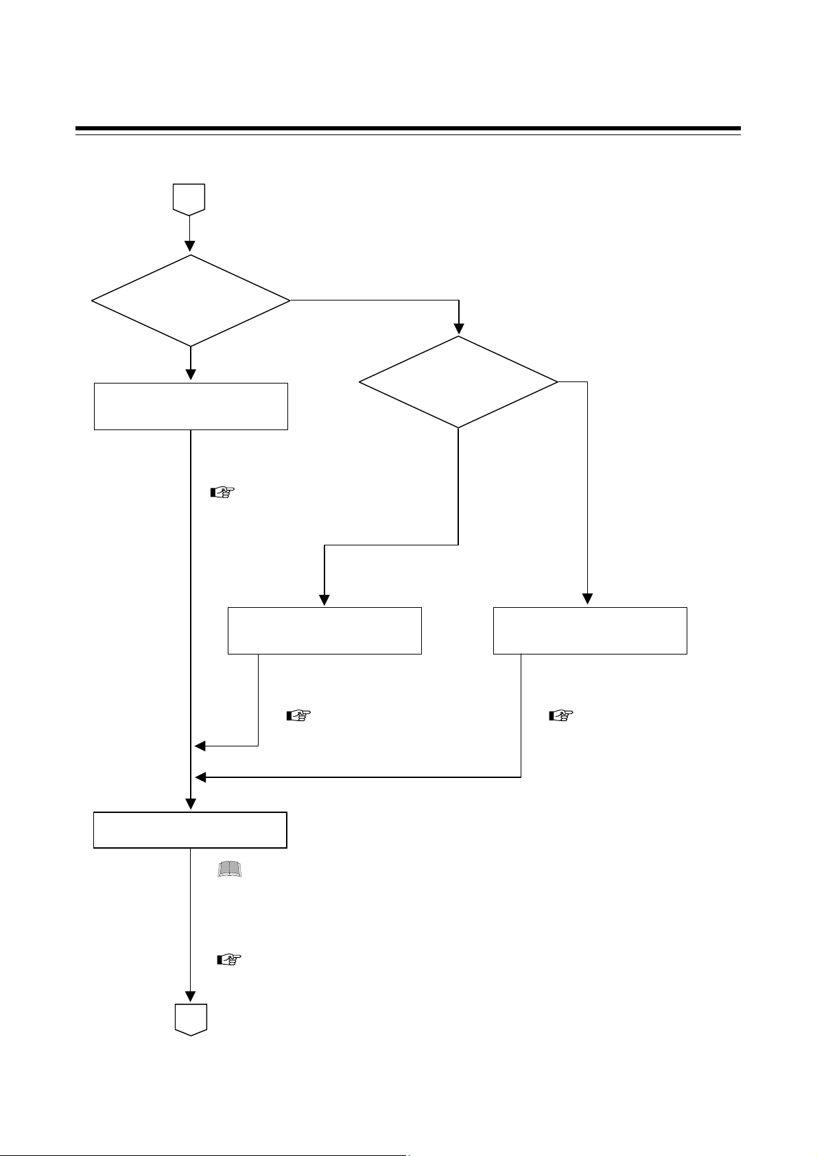
3. SETTING PROCEDURE TO OPERATION
y
Continued from the previous page.
A
Do execute
IP address setting
by a Telnet ?
NO
YES
IP address setting
by a Telnet
The IP address is set by using
Telnet.
See 6.1 Setting by Telnet
(P. 16).
IP address setting
by a web browser
The IP address is set by using
a web browser.
See 6.2 Setting by the
Web Browser (P. 21).
Initial setting data setting
Set the Input scale high/low limit, Input range decimal point position, Control
t
Before setting operation data items, always set initial setting data
items so as to satisfy the specification used.
pe, Event type etc.
For initial setting data items, see 7.6.2 Initial setting data items (P. 51) or
8.2 Initial Setting Data Items (P. 86).
B
Do execute
IP address setting by a
web browser ?
YES
NO
IP address setting
by the DIP switches
The IP address is set by using
the DIP switches.
See 6.3 Setting by the
DIP Switch (P. 24).
Continued on the next page.
4
IMS01P09-E4
Page 11

Continued from the previous page.
B
Power ON again
The initial setting data items thus set are registered by turning on the
SRV power supply again.
Operation data setting
Set data to be related to the control.
Operation mode setting
Select the operation mode in the Auto/Manual transfer.
(Factory set value: AUTO)
Control RUN
Set the control RUN/STOP transfer to the “RUN.”
(Factory set value: STOP)
Operation start
3. SETTING PROCEDURE TO OPERATION
For data, see 7.6.1 Normal setting data items (P. 43) or 8.1 Normal
Setting Data Items (P. 57).
IMS01P09-E4
5
Page 12
4. COMMUNICATION SETTING
To prevent electric shock or instrument failure, always turn off the power
before setting the switch.
WARNING
!
To prevent electric shock or instrument failure, never touch any section other
than those instructed in this manual.
CAUTION
Do not separate the module mainframe from the terminal base with the power turned on. If
separated, adjusted data may be destroyed; control be stopped, and no return can be made.
Set the following communication setting before operation.
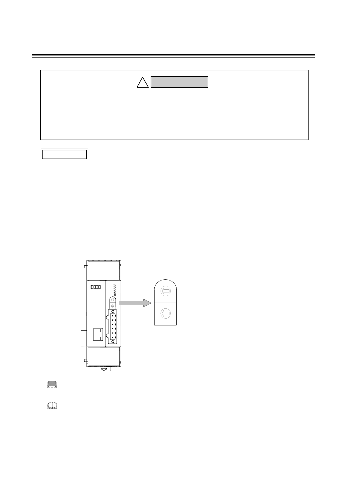
4.1 Module Address Setting
When using two or more modules, set the desired address to each module.
Set the module address by address setting switch of front of module. For this setting, use a small blade
screwdriver.
Address setting switch
FAIL/RUN
RX/TX
EVENT1
EVENT2
EVENT3
EVENT4
3
2
4
1
5
5 5
0
6
9
7
8
3
2
4
1
5
0
6
9
7
8
Setting range: 0 to 30
(Factory set value: 0)
Set the module address such that it is different to the other addresses in the same unit.
Otherwise, problems or malfunction may result.
3
2
4
1
5
5 5
0
9
8
3
2
1
0
9
8
High-order digit setting
6
7
(set value × 10)
4
5
Low-order digit setting
6
7
(set value × 1)
The above figure is V-TIO-P/V-TIO-Q module. The figure of other TIO module is the same
as a V-TIO-P/V-TIO-Q module.
6 IMS01P09-E4
Page 13

4. COMMUNICATION SETTING
The channel number for the module address
The module address can be freely set with any numbers from 0 to 30.
In addition, to each module address, the relevant temperature control channel is assigned. Each
temperature control channel number can be calculated from the following equation.
Temperature control channel number of communication
[Setting example]
V-TIO-P module
= (Module address × 2) + Temperature control channel number of module
Temperature control module [extension type] V-TIO-B
Module
address
30
CH1
CH61
CH2
CH62
Temperature contr ol
channel num ber of
module
Temperature contr ol
channel num ber of
communication
CH1
CH1
CH2
CH2
CH1
CH3
CH2
CH4
CH1
CH21
CH2
CH22
CH1
CH23
CH2
CH24
CH1
CH41
CH2
CH42
21201110 10
CH1
CH2
CH43
CH44
For heat/cool control, data in the second channel of each module becomes invalid.
[Example] If module addresses of one V-TIO-Q module and six V-TIO-D modules which
are heat/cool temperature control modules are set as follows by the free setting,
data in odd channels is used because data in even channels is invalid.
Valid channel number: 1, 3, 21, 23, 41, 43, 61
Invalid channel number: 2, 4, 22, 24, 42, 44, 62
V-TIO-Q module
Temperature control module [extension type] V-TIO-D
Module
address
Valid channel
Invalid channel
IMS01P09-E4
CH1
CH1
CH2
CH2
CH1
CH3
CH2
CH4
CH1
CH21
CH2
CH22
CH1
CH23
CH2
CH24
CH1
CH41
CH2
CH42
CH1
CH43
212011101 0
CH2
CH44
CH1
CH61
30
CH2
CH62
Temperature control
channel number of
module
Temperature control
channel number of
communication
7
Page 14
4. COMMUNICATION SETTING
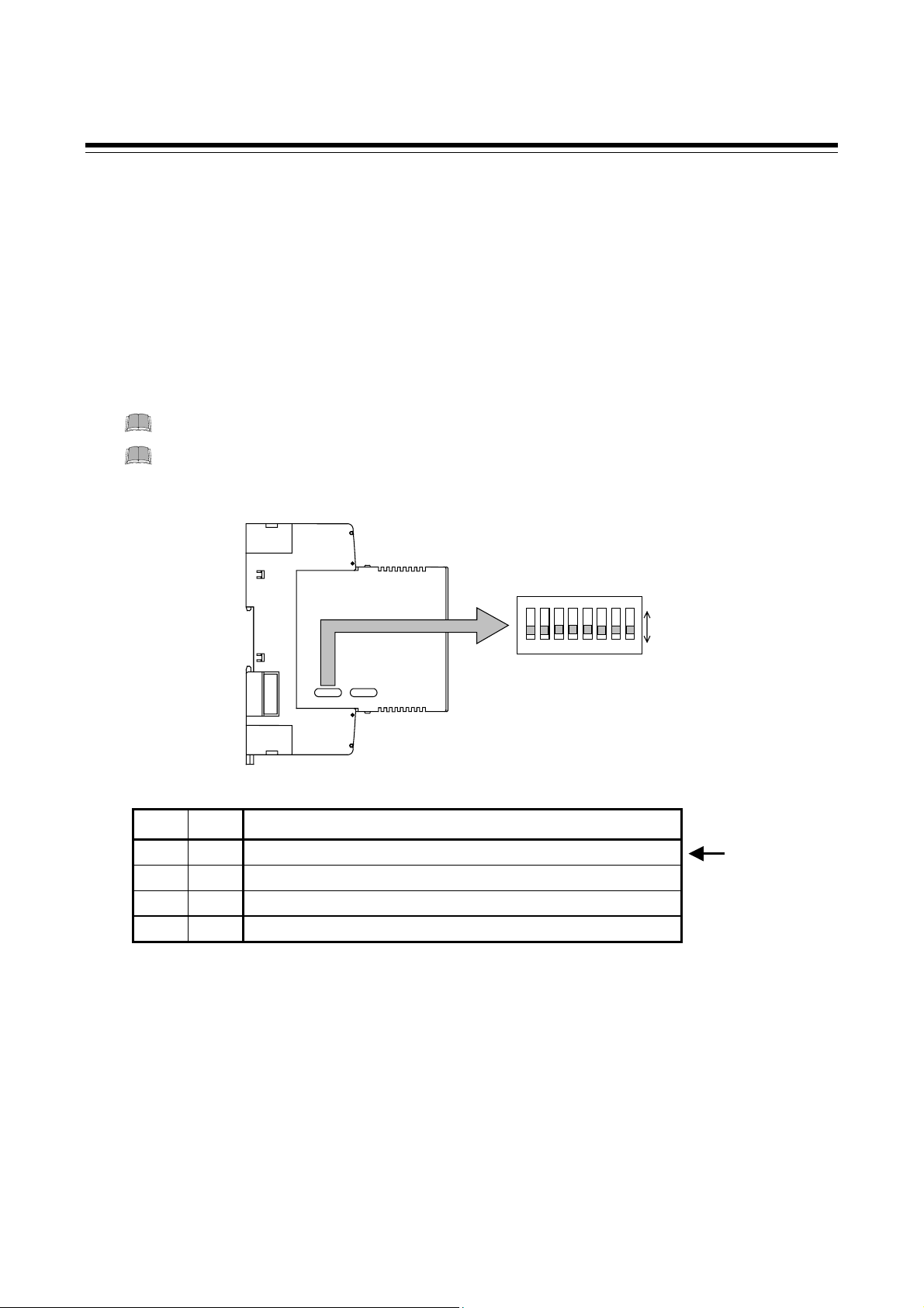
4.2 Internal Communication Setting
Internal communication is used for data transfer between modules within the SRV unit.
The setting is made on the Ethernet communication and temperature control sides of the
V-TIO-P/V-TIO-Q module.
Setting of Ethernet communication side
With the DIP switch 1 which there is on the left side of V-TIO-P/V-TIO-Q module, select internal
communication speed.
Switch No. 3 to 8: OFF fixed (Don’t change this one)
Set the communication speed to the same value as the setting on the temperature
control side (DIP switch 3).
Left side view
1 2 Communication speed
OFF OFF
ON OFF
OFF ON
ON ON
38400 bps
9600 bps
19200 bps
38400 bps
DIP switch 1
ON
ON
1234567 8
1234567 8
ON
OFF
Factory
set value
8
IMS01P09-E4
Page 15

4. COMMUNICATION SETTING
Setting of temperature control side
With the DIP switch 3 which there is on the right side of V-TIO-P/V-TIO-Q module, select internal
communication speed and data bit configuration.
Switch No. 6: ON fixed (Don’t change this one)
Switch No. 7, 8: OFF fixed (Don’t change this one)
Set the communication speed to the same value as the setting on the Ethernet
communication side (DIP switch 1).
When connecting two or more modules (V-TIO-A, V-TIO-B, V-TIO-C or V-TIO-D) to
the V-TIO-P/V-TIO-Q module, match all of their communication speed and data bit
configuration settings with the internal settings of the V-TIO-P/V-TIO-Q module.
Right side view
1 2 Communication speed
OFF OFF
ON OFF
OFF ON
ON ON
9600 bps
19200 bps
38400 bps
Don’t set this one
3 4 5 Data bit configuration
OFF OFF OFF
OFF OFF ON
Don’t set this one
OFF ON OFF
OFF ON ON
ON OFF OFF
Data 8-bit, without parity, Stop 1-bit
ON OFF ON
ON ON OFF
Don’t set this one
ON ON ON
DIP switch 3
ON
ON
12345678
12345678
ON
OFF
Factory
set value
Factory
set value
IMS01P09-E4
9
Page 16

4. COMMUNICATION SETTING
4.3 Termination Resistor Setting of Internal communication
Procedure for setting a termination resistor to internal communication (RS-485) and its setting position
are described in the following.
Termination resistor setting position
Set a termination resistor to the communication line termination in the module located in the position
farthermost from the V-TIO-P/V-TIO-Q module.
V-TIO-P/V-TIO-Q module
Temperature control module
[extension type] V-TIO- B/V-TIO-D
Setting procedure of termination resistor
SRV unit
Internal communication
(RS-485)
Turn on the termination
resistor of this module.
As no termination resistor is externally connected to the temperature control (TIO) module [extension
type] V-TIO-B (or V-TIO-D), the termination resistor built in the module is connected by switch
selection.
1. Turn off the power supply of the module.
Do not separate the module mainframe from the terminal base with the power turned on. If
separated, adjusted data may be destroyed; control be stopped, and no return can be made.
2. Pull out the module mainframe itself toward you while pushing the locks at its top and bottom,
and then separate it from the terminal base.
Upper-side lock
Top view
Terminal base
Module mainframe
(1) Push
(2) Pull out
Lower-side lock
10
Bottom view
(1) Push
Removing the module mainframe
IMS01P09-E4
Page 17

Ω
3. Turn on the termination resistor transfer switch in the terminal base.
Termination resistor transfer switch
4. COMMUNICATION SETTING
Termination resistor ON (120
1/2 W)
Termination resistor OFF
Factory set value: OFF
A terminal base of the state which removed module mainframe
4. Push the module mainframe thus separated in the terminal base until firmly locked.
Terminal base
Module mainframe
Push the module
mainframe until
firmly locked
Mounting the module mainframe
IMS01P09-E4
11
Page 18

(
5. WIRING
To prevent electric shock or instrument failure, turn off the power before
connecting or disconnecting the instrument and peripheral equipment.
WARNING
!
CAUTION
Connect connectors correctly in the right position. If it is forcibly pushed in with pins in
the wrong positions, the pins may be bent resulting in instrument failure.
When connecting or disconnecting the connectors, do not force it too far to right and left
or up and down, but move it on the straight. Otherwise, the connector pins may be bent,
causing instrument failure.
When disconnecting a connector, hold it by the connector itself. Disconnecting
connectors by yanking on their cables can cause breakdowns.
To prevent malfunction, never touch the contact section of a connector with bare hands
or with hands soiled with oil or the like.
To prevent malfunction, connect cable connectors securely, then firmly tighten the
connector fastening screws.
To prevent damage to cables, do not bend cables over with excessive force.
If the instrument is easily affected by noise, use the ferrite core in the both ends of the
communication cable (nearest the connector).
5.1 Wiring Configuration
When directly connected to client
Computer
(Client)
Internal Communication
Ethernet
V-TIO-P/V-TIO-Q module
Server)
Up to 30 temperature control modules can be connected to one V-TIO-P/V-TIO-Q module.
SRV unit
(RS-485)
TIO module [extension type]
V-TIO-B/V-TIO-D
12 IMS01P09-E4
Page 19

(
)
When use network hub
Computer
(Client)
Network Hub
Ethernet
Up to 30 temperature control modules can be connected to one V-TIO-P/V-TIO-Q module.
Basically, one client corresponds to one server (SRV) (i.e. one to one). However, one client
can communicate with two or more servers depending on the program on the client side, but
two or more clients cannot communicate with one server.
Ethernet
V-TIO-P/V-TIO-Q module
Server
5. WIRING
SRV unit
Internal Communication
(RS-485)
TIO module [extension type]
V-TIO-B/V-TIO-D
Computer
(Client)
V-TIO-P/V-TIO-Q module
(Server)
Network Hub
Ethernet
Ethernet
SRV unit
Ethernet
SRV unit
V-TIO-P/V-TIO-Q module
(Server)
TIO module [extension type]
V-TIO-B/V-TIO-D
IMS01P09-E4 13
Page 20

5. WIRING
r
t
5.2 Wiring Details
Pin layout of modular connector
Modular connecto
for Etherne
V-TIO-P/V-TIO-Q module
RJ-45
8: Unused
7: Unused
6: RX−
5: Unused
4: Unused
3: RX+
2: TX−
1: TX+
Connector pin number and signal details
Pin No. Signal name Symbol
1
2
3
4 Unused
5 Unused
6
7 Unused
8 Unused
The cable is provided by the customer.
Used cable: The cable is based on the 10BASE-T or the 100BASE-TX standard of
Used connector: RJ-45 type
Send data + TX+
Send data − TX−
Receive data + RX+
Receive data − RX−
Ethernet.
14
IMS01P09-E4
Page 21

+TX−RX+
−
Wiring example
When directly connected to client
Use a cross cable when directly connected to the client (such as computer).
Computer
V-TIO-P/V-TIO-Q
5. WIRING
module
TX
+
TX
−
RX
+
RX
−
Cross cable
When use network hub
Use straight cables when connected to the network hub.
Computer
TX
TX
RX
RX
+
−
+
−
Network Hab
TX+
TX−
RX+
RX−
TX
RX
TX+
TX−
RX+
RX−
V-TIO-P/V-TIO-Q
module
TX+
TX−
RX+
RX−
IMS01P09-E4
Straight cable Straight cable
Cross cables may be used depending on the connecting device used. Therefore, follow the
instructions for the respective device.
15
Page 22

6. IP ADDRESS SETTING
Set an IP address of a V-TIO-P/V-TIO-Q module.
Three types of IP address setting are available: “setting by Telnet,” “setting by Web browser” and
“setting by DIP switch.”
Confirm the IP address number to the network administrator of the network (LAN) to
which the V-TIO-P/V-TIO-Q module is connected.
6.1 Setting by Telnet
Set the IP address by the software “Telnet” attached to Windows.
Preparations before setting
When setting the IP address by Telnet, it is necessary to coincide the 1st to 3rd bytes and masking
range of the IP address of the client (computer) which starts Telnet with those of the IP address of the
V-TIO-P/V-TIO-Q module.
1. Connect the V-TIO-P/V-TIO-Q module and client, and then turn on the power.
For wiring procedure, see 5. WIRING (P. 12).
2. The IP address of the V-TIO-P/V-TIO-Q module is set to a factory set value of “192.168.1.1.”
As it is necessary to coincide the 1st to 3rd byte values of this IP address with those of the IP
address of the client, change the IP address of the client to “192.168.1.” (: Any value in the
range of 0 to 255, but other than 1).
3. As the subnet mask of the V-TIO-P/V-TIO-Q module is “255.255.255.0,” also change the subnet
mask of the client to “255.255.255.0.”
After the IP address of the server is set, return the present IP address of the client to the
original address or change to the address meeting the network to be connected.
It is possible to set the IP address of the V-TIO-P/V-TIO-Q module using the client already
connected to the network. However, as the IP address of the client is changed, that client is
disconnected from the network so far connected.
In addition, when setting the IP address by this method, confirm to the network administrator
whether or not no problem arises.
16 IMS01P09-E4
Page 23

6. IP ADDRESS SETTING
Setting example
An example of setting the IP address to “192.168.1.3” is shown in the following.
1. Display the MS-DOS prompt (command prompt); enter the following command and then press
the Enter key.
C:¥>telnet 192.168.1.1 9999
2. Device information on the module (V-TIO-P/V-TIO-Q module) whose IP address is
“192.168.1.1” is displayed. Finally, as the message “Press Enter to go into Setup Mode” is
displayed, press the Enter key to go into Setup Mode.
MAC address 00204A8064BD
Software version 01.3 (030612) XPTE
Press Enter to go into Setup Mode
If the timing of pressing the Enter key is late, the message “Connection with Host was cut
off” is displayed and thus the client is disconnected from the V-TIO-P/V-TIO-Q module.
Therefore if the message “Press Enter to go into Setup Mode” is displayed, immediately
press the Enter key.
If disconnected, try again from “1.”
3. If entered into Setup Mode, the present Ethernet information is displayed.
Finally, eight choices are displayed as “Change Setup:.” Therefore enter “0” after “Your
choice ?” and then press the Enter key.
*** basic parameters
Hardware: Ethernet TPI
IP addr 192.168.1.1, no gateway set,netmask 255.255.255.000
*************** Security ***************
SNMP is enabled
SNMP Community Name: public
Telnet Setup is enabled
TFTP Download is enabled
Port 77FEh is enabled
Web Server is enabled
ECHO is disabled
Enhanced Password is disabled
*************** Channel 1 **************
Baudrate 38400, I/F Mode 7C, Flow 00
Port 00502
Remote IP Adr: --- none ---, Port 00000
Connect Mode: C0 Disconn Mode: 00
Flush Mode: 80
Pack Cntrl : 00
Continued on the next page.
IMS01P09-E4
17
Page 24

6. IP ADDRESS SETTING
Continued from the previous page.
*************** Expert *****************
TCP Keepalive : 45s
ARP cache timeout: 600s
*************** E-mail *****************
Mail server: 0.0.0.0
Unit :
Domain :
Recipient 1:
Recipient 2:
*** Trigger 1
Serial Sequence: 00,00
CP1: X
CP2: X
CP3: X
Message:
Priority : L
Min. notification interval: 1 s
Re-notification interval : 0 s
*** Trigger 2
Serial Sequence: 00,00
CP1: X
CP2: X
CP3: X
Message:
Priority : L
Min. notification interval: 1 s
Re-notification interval : 0 s
*** Trigger 3
Serial Sequence: 00,00
CP1: X
CP2: X
CP3: X
Message:
Priority : L
Min. notification interval: 1 s
Re-notification interval : 0 s
Change Setup:
0 Server configuration
1 Channel 1 configuration
3 E-mail settings
5 Expert settings
6 Security
7 Factory defaults
8 Exit without save
9 Save and exit Your choice ? 0
Enter “0” (Server configuration),
and press the Enter key.
18
IMS01P09-E4
Page 25

4. Selecting “0: Server configuration” makes ready to set the IP address.
Enter the IP address one byte by one byte.
As the following display appears, enter “192” into the first byte and then press the Enter key.
IP Address : (192) 192
Next, enter “168” into the second byte and then press the Enter key.
IP Address : (192) 192.(168) 168
Enter “1” into the third byte and then press the Enter key.
IP Address : (192) 192.(168) 168.(001) 1
6. IP ADDRESS SETTING
Enter “3” into the fourth byte and then press the Enter key.
IP Address : (192) 192.(168) 168.(001) 1.(001) 3
5. After the IP address is entered, the following display appears. Therefore press the Enter key to
proceed to the next.
IP Address : (192) 192.(168) 168.(001) 1.(001) 3
Set Gateway IP Address (N) N
In addition, as one line is displayed, press the Enter key to proceed to the next.
IP Address : (192) 192.(168) 168.(001) 1.(001) 3
Set Gateway IP Address (N) N
Netmask: Number of Bits for Host Part (0=default) (16)
Further, as more one line is displayed, press the Enter key to proceed to the next.
IP Address : (192) 192.(168) 168.(001) 1.(001) 3
Set Gateway IP Address (N) N
Netmask: Number of Bits for Host Part (0=default) (16)
Change telnet config password (N) N
IMS01P09-E4
19
Page 26

6. IP ADDRESS SETTING
6. As “Change Setup:” is displayed again, enter “9” after “Your choice ?” and then press the Enter
key.
Change Setup:
0 Server configuration
1 Channel 1 configuration
3 E-mail settings
5 Expert settings
Enter “9” (Save and exit),
and press the Enter key.
6 Security
7 Factory defaults
8 Exit without save
9 Save and exit Your choice ? 9
7. “Parameters stored ...” is displayed and thus the setting is finished.
Parameters stored ...
Connection with Host was cut off
20
IMS01P09-E4
Page 27

6. IP ADDRESS SETTING
6.2 Setting by the Web Browser
It is possible to set the IP address by using the Web browser (such as Internet Explorer).
Preparations before setting
When setting the IP address by Web browser, it is necessary to coincide the 1st to 3rd bytes and
masking range of the IP address of the client (computer) which starts Web browser with those of the
IP address of the V-TIO-P/V-TIO-Q module.
1. Connect the V-TIO-P/V-TIO-Q module and client, and then turn on the power.
For wiring procedure, see 5. WIRING (P. 12).
2. The IP address of the V-TIO-P/V-TIO-Q module is set to a factory set value of “192.168.1.1.”
As it is necessary to coincide the 1st to 3rd byte values of this IP address with those of the IP
address of the client, change the IP address of the client to “192.168.1. ” (: Any value in the
range of 0 to 255, but other than 1).
3. As the subnet mask of the V-TIO-P/V-TIO-Q module is “255.255.255.0,” also change the subnet
mask of the client to “255.255.255.0.”
After the IP address of the server is set, return the present IP address of the client to the
original address or change to the address meeting the network to be connected.
It is possible to set the IP address of the V-TIO-P/V-TIO-Q module using the client already
connected to the network. However, as the IP address of the client is changed, that client is
disconnected from the network so far connected.
In addition, when setting the IP address by this method, confirm to the network administrator
whether or not no problem arises.
IMS01P09-E4
21
Page 28

6. IP ADDRESS SETTING
Setting example
An example of setting the IP address to “192.168.1.3” is shown in the following.
1. Start the Web browser; enter the present IP address “192.168.1.1” into the address bar and then
press the Enter key.
2. The initial setting applet starts. “Selected Channel: 1” is displayed on the main display with “Port
Properties” selected on the Menu display on the left side of the screen.
Under this condition, click the Server Properties button on the Menu display.
Do not change the contents of “Selected Channel: 1.” If changed, device failure or
error may result.
Click
22
IMS01P09-E4
Page 29

6. IP ADDRESS SETTING
3. Display the Server Properties screen.
Set “192.168.1.3” in IP Address.
Set
192.168.1.3
Do not change any items other than the IP Address. If so, device failure or error
may result.
4. Clicking the Update Settings button on the Menu display updates the setting to display the
following message.
Click
5. Enter the new IP address “192.168.1.3” into the address bar as instructed by message and then
press the Enter key. Thus, a new IP address setting screen appears to end the setting.
IMS01P09-E4
23
Page 30

6. IP ADDRESS SETTING
6.3 Setting by the DIP Switch
It is possible to set the IP address by DIP switch with Ethernet not connected.
DIP switches used are “DIP switch 1” and “DIP switch 2” on the left side of the module.
DIP switch 1
DIP switch 2
Left side view of V-TIO-P/V-TIO-Q module
Factory set value of an IP address of a V-TIO-P/V-TIO-Q module is “192.168.1.1.”
Setting example
An example of setting the IP address to “192.168.1.3” is shown in the following.
1. Setting preparations
Turn on No. 6 and off No. 7 of DIP switch 1 with the power turned off.
It does not matter whether Nos. 1 to 5 and No. 8 of DIP switch 1 is turned on or off.
2. Power ON
Turning the power on goes to IP address setup mode. Thus, the FAIL lamp lights.
In addition, the first byte (most significant byte) of the IP address is set to the entry wait state.
(RUN lamp: ON, TX lamp: ON, RX lamp: OFF)
DIP switch 1
ON
ON
1 2 3 4 5 6 7 8
1 2 3 4 5 6 7 8
ON
OFF
FAIL lamp
ON
No. 6: ON
No. 7: OFF
RUN lamp
ON
RX lamp
OFF
TX lamp
ON
24
IMS01P09-E4
Page 31

3. Input the first byte “192”
Enter the first byte (most significant byte) by DIP switch 2. As the first byte (most significant
byte) is entered with “192,” this number corresponds to a binary number of “11000000.”
Conduct the following setting with No. 8 of DIP switch 2 set to the most significant bit.
DIP switch 2
ON
ON
1 2 3 4 5 6 7 8
1 2 3 4 5 6 7 8
4. Decision of the first byte input
In order to establish the setting of DIP switch 2, turn off No. 6 of DIP switch 1.
In addition, the second byte of IP address is set to the entry wait state.
(RUN lamp: ON, TX lamp: OFF, RX lamp: OFF)
DIP switch 1
ON
ON
1 2 3 4 5 6 7 8
1 2 3 4 5 6 7 8
5. Input the second byte “168”
Enter the second byte by DIP switch 2. As the second byte is entered with “168,” this number
corresponds to a binary number of “10101000.” Conduct the following setting with No. 8 of DIP
switch 2 set to the most significant bit.
DIP switch 2
ON
ON
1 2 3 4 5 6 7 8
1 2 3 4 5 6 7 8
6. Decision of the second byte input
In order to establish the setting of DIP switch 2, turn on No. 6 of DIP switch 1.
In addition, the third byte of IP address is set to the entry wait state.
(RUN lamp: OFF, TX lamp: ON, RX lamp: OFF)
DIP switch 1
ON
ON
1 2 3 4 5 6 7 8
1 2 3 4 5 6 7 8
No. 6
OFF
No. 6
ON
ON
No. 1 to 6: OFF
No. 7, 8: ON
OFF
ON
No. 1, 2, 3, 5, 7: OFF
No. 4, 6, 8: ON
OFF
FAIL lamp
ON
FAIL lamp
ON
6. IP ADDRESS SETTING
RUN lamp
ON
RUN lamp
OFF
TX lamp
OFF
TX lamp
ON
RX lamp
OFF
RX lamp
OFF
IMS01P09-E4
25
Page 32

6. IP ADDRESS SETTING
7. Input the third byte “1”
Enter the third byte by DIP switch 2. As the third byte is entered with “1,” this number
corresponds to a binary number of “00000001.” Conduct the following setting with No. 8 of DIP
switch 2 set to the most significant bit.
DIP switch 2
ON
ON
1 2 3 4 5 6 7 8
1 2 3 4 5 6 7 8
8. Decision of the third byte input
In order to establish the setting of DIP switch 2, turn off No. 6 of DIP switch 1.
In addition, the fourth byte of IP address is set to the entry wait state.
(RUN lamp: OFF, TX lamp: OFF, RX lamp: OFF)
DIP switch 1
ON
ON
1 2 3 4 5 6 7 8
1 2 3 4 5 6 7 8
9. Input the fourth byte “3”
Enter the fourth byte by DIP switch 2. As the fourth byte is entered with “3,” this number
corresponds to a binary number of “00000011.” Conduct the following setting with No. 8 of DIP
switch 2 set to the most significant bit.
DIP switch 2
ON
ON
1 2 3 4 5 6 7 8
1 2 3 4 5 6 7 8
10. Decision of the fourth byte input
In order to establish the setting of DIP switch 2, turn on No. 6 of DIP switch 1. Thus, the IP
address setting is finished and the FAIL lamp goes off.
(RUN lamp: OFF, TX lamp: OFF, RX lamp: OFF)
DIP switch 1
ON
ON
1 2 3 4 5 6 7 8
1 2 3 4 5 6 7 8
No. 6
OFF
No. 6
ON
ON
No. 1: ON
No. 2 to 8: OFF
OFF
ON
No. 1, 2: ON
No. 3 to 8: OFF
OFF
FAIL lamp
ON
FAIL lamp
OFF
RUN lamp
OFF
RUN lamp
OFF
RX lamp
OFF
TX lamp
OFF
RX lamp
OFF
TX lamp
OFF
26
IMS01P09-E4
Page 33

11. Decision of the IP address
After a lapse of a few seconds, the RUN lamp lights and the IP address is established.
The FAIL, TX and RX lamps flash until the IP address is established and they go off after the IP
address is established.
12. Power OFF
Turn the power off and also turn off No. 6 of DIP switch 1. In addition, turn off all Nos. of DIP
switch 2.
If the power is turned on, operation starts at the IP address thus set.
FAIL lamp
Flashing
FAIL lamp
OFF
RUN lamp
OFF
RUN lamp
ON
6. IP ADDRESS SETTING
RX lamp
Flashing
TX lamp
Flashing
A few seconds later
RX lamp
OFF
TX lamp
OFF
IMS01P09-E4
27
Page 34

7. MODBUS/TCP PROTOCOL
Modbus/TCP is an open field network provided with the Modbus protocol on the TCP/IP protocol of
Ethernet.
The data request side is called “client” (such as computer) and the data response (supply) side is called
“server” (SRV).
7.1 Message Configuration
Modbus ADU (Application Data Unit) on TCP/IP is in the following configuration.
MBAP Header
Transaction
Identifier
2 bytes
MBAP Header
7 bytes
Modbus TCP/IP ADU
Function code
1 byte
Protocol
Identifier
2 bytes
PDU (Protocol Data Unit)
2 to 255 bytes
Data
1 to 254 bytes
Data Length
2 bytes
Unit Identifier
1 byte
MBAP (Modbus Application Protocol) header contains the following fields: Transaction Identifier,
Protocol Identifier, Data Length and Unit Identifier.
Fields Length Request (Client) Response (Server)
Transaction
Identifier
2 bytes
Unused
However, data corresponding to
Returns data from the client as is
two bytes is sent
Protocol
2 bytes
Identifier
Data Length 2 bytes
Unit Identifier 1 byte
“0” fixed
(Modbus protocol = 0)
The total number of bytes of
Unit Identifier and PDU
(256 bytes max.)
Unused
Returns data from the client as is
The total number of bytes of
Unit Identifier and PDU
(256 bytes max.)
Returns data from the client as is
However, data corresponding to
one byte is sent
28 IMS01P09-E4
Page 35

PDU
PDU (Protocol Data Unit) consists of two blocks: function codes and data.
Fields Length Request (Client) Response (Server)
7. MODBUS/TCP PROTOCOL
Function code 1 byte
Data 1 to 254
bytes
03H: Read holding registers
06H: Write single register
08H: Diagnostics (loopback test)
10H: Write multiple registers
17H: Read/write multiple
registers
Data meeting the function code
Normal response
Returns data from the client as is
Error response
80H + Function code
Normal response
Data meeting the function code
Error response
Exception code
01H: Illegal function code
02H: Illegal register address
03H: Illegal data value
04H: Server failure
06H: Server busy
IMS01P09-E4 29
Page 36

7. MODBUS/TCP PROTOCOL
7.2 Function Code
Function code contents
Function code
Function Contents
03H
06H
08H
10H
Read holding registers
Write single register Set value, PID constants, event set value, etc.
Diagnostics (loopback test) Loopback test
Write multiple registers Set value, PID constants, event set value, etc.
Measured value, Control output value, Current
transformer input value, Event status, etc.
Measured value, Control output value, Current
17H
Read/write multiple registers
transformer input value, Event status, Set value,
PID constants, event set value, etc.
Message (PDU) length of each function [Unit: byte]
Function code Function
Request message Response message
Min Max Min Max
03H
06H
08H
10H
17H
Read holding registers
Write single register
Diagnostics (loopback test)
Write multiple registers
Read/write multiple registers
5 5 4 252
5 5 5 5
5 5 5 5
8 252 5 5
12 246 4 238
7.3 Server (SRV) Responses
Normal response
• In the response message of the read holding registers, the server (SRV) returns the “Function
code,” “Number of data items” and the “Read out data” as the response message.
• In the response message of the write single register and diagnostics (loopback test), the server
(SRV) returns the same message as the request message.
• In the response message of the write multiple registers, the server (SRV) returns the “Function
code,” the “Register address number” and the “Number of register” as the response message.
• In the response message of the read/write multiple registers, the server (SRV) returns the “Function
code,” “Number of write data items” and the “Read out data” as the response message.
30
IMS01P09-E4
Page 37

Defective message response
7. MODBUS/TCP PROTOCOL
• If the request message from the client is defective, except for
Function code
transmission error, the server (SRV) returns the exception response
message without any action.
• If the self-diagnostic function of the server (SRV) detects an error,
the server will return an exception response message to all request
Exception code
Exception response
message
messages.
• The function code of each exception response message is obtained by adding “80H” to the function
code of the request message.
Exception
code
Contents Causes
01H Illegal function code An unsupported function code was specified
02H Illegal register address When the mismatched register address is specified.
03H Illegal data value
• The number of specified data points was out of the
following range during data read or write.
Function code 03H: 1 to 125
Function code 10H: 1 to 123
Function code 17H: 1 to 118
• When the data written exceeds the setting range
04H Server failure
State under which the server cannot normally
respond (An error occurred in the server)
06H Server busy
State under which the server cannot immediately
respond (The server is being initialized)
Exception code priority order
01H > 03H > 02H > 04H > 06H
• Order of a no response in PDU data length error
When Specified PDU data length < Received PDU data length:
01H > No response in PDU data length error > 03H
When Specified PDU data length > Received PDU data length:
No response in PDU data length error > 01H
• Order when reading/writing the register contents
When there is 02H or 03H only for read processing:
01H > 04H > 06H > 03H > 02H
• Order when out of the setting range
For 03H when out of the setting range: 01H > 02H > 04H > 06H > 03H
No response
The server (SRV) ignores the request message and does not respond when:
• The IP address does not coincide.
• The server (SRV) is not connected to the network.
• The PDU (Protocol Data Unit) data length is abnormal.
When the PDU data length specified by the request message does not coincide with the number of
bytes received as one TCP packet.
SRV determines whether or not communication messages correspond to one packet by time-out
(approx. 12 ms) between characters.
IMS01P09-E4
31
Page 38

7. MODBUS/TCP PROTOCOL
N
7.4 Message Format
7.4.1 Read holding registers [03H]
The request message specifies the starting register address number and quantity of register addresses
to be read.
The contents of the registers are entered in the response message as data, divided into two parts: the
high-order eight bits and low-order eight bits, arranged in the order of the register numbers.
Example: The contents of the three registers from 0000H to 0002H are the read out.
Request message [Client]
Transaction Identifier High 00H
Low 00H
Protocol Identifier High 00H
Low 00H
Data Length High 00H
Low 06H
Unit Identifier 00H
Function code 03H
Register address High 00H
Low 00H
Quantity High 00H
(Number of words) Low 03H
MBAP Header
First register address
The setting must be between 1 (0001H) and
125 (007DH).
Normal response message [Server]
Transaction Identifier High 00H
Low 00H
Protocol Identifier High 00H
Low 00H
MBAP Header
Data Length High 00H
Low 09H
Unit Identifier 00H
Function code 03H
Number of data (byte) 06H
umber of registers × 2
First register High 00H
contents Low 78H
Next register High 00H
contents Low 00H
Next register High 00H
contents Low 14H
32
IMS01P09-E4
Page 39

Exception response message [Sever]
Transaction Identifier High 00H
Low 00H
Protocol Identifier High 00H
Low 00H
MBAP Header
Data Length High 00H
Low 03H
Unit Identifier 00H
80H + Function code 83H
Exception code 03H
When the data exceeds the setting range
7. MODBUS/TCP PROTOCOL
IMS01P09-E4
33
Page 40

7. MODBUS/TCP PROTOCOL
7.4.2 Write single register [06H]
The request message specifies data to be written into the designated register.
Write data items are arranged in the request message in order starting from the smallest register
address number. In addition, each register address is assigned in the order of high-order eight bits and
low-order eight bits, respectively.
Example: When 100 (64H) is written to the register 0010H
Request message [Client]
Transaction Identifier High 00H
Low 00H
Protocol Identifier High 00H
Low 00H
Data Length High 00H
Low 06H
Unit Identifier 00H
Function code 06H
Register address High 00H
Low 10H
Write data High 00H
Low 64H
Normal response message [Server]
Transaction Identifier High 00H
Low 00H
Protocol Identifier High 00H
Low 00H
Data Length High 00H
Low 06H
Unit Identifier 00H
Function code 06H
Register address High 00H
Low 10H
Write data High 00H
Low 64H
Exception response message [Sever]
Transaction Identifier High 00H
Low 00H
Protocol Identifier High 00H
Low 00H
Data Length High 00H
Low 03H
Unit Identifier 00H
80H + Function code
86H
Exception code 03H
MBAP Header
Any data within the range
Contents will be the same as request message data
MBAP Header
When the data exceeds the setting range
34
IMS01P09-E4
Page 41

7. MODBUS/TCP PROTOCOL
7.4.3 Diagnostics (Loopback test) [08H]
The client's request message will be returned as the response message from the server.
This function checks the communication system between the client and server.
Example: Loopback test
Request message [Client]
Transaction Identifier High 00H
Low 00H
Protocol Identifier High 00H
Low 00H
Data Length High 00H
Low 06H
Unit Identifier 00H
Function code 08H
Test code High 00H
Low 00H
Data High 1FH
Low 34H
Normal response message [Server]
Transaction Identifier High 00H
Low 00H
Protocol Identifier High 00H
Low 00H
Data Length High 00H
Low 06H
Unit Identifier 00H
Function code 08H
Test code High 00H
Low 00H
Data High 1FH
Low 34H
Exception response message [Sever]
Transaction Identifier High 00H
Low 00H
Protocol Identifier High 00H
Low 00H
Data Length High 00H
Low 03H
Unit Identifier 00H
80H + Function code
88H
Exception code 06H
MBAP Header
Test code must be set to 00H
Any pertinent data
Contents will be the same as request message data
MBAP Header
When server is busy
IMS01P09-E4
35
Page 42

7. MODBUS/TCP PROTOCOL
N
7.4.4 Write multiple registers [10H]
Each data is written to registers in specified quantities starting from the specified register address.
Write data items are arranged in the request message in order starting from the smallest register
address number. In addition, each register address is assigned in the order of high-order eight bits and
low-order eight bits, respectively.
Example: When 100 (64H) and 30 (1EH) are written to the register 0010H and 0011H (two in
total)
Request message [Client]
Transaction Identifier High 00H
Low 00H
Protocol Identifier High 00H
Low 00H
Data Length High 00H
Low 0BH
Unit Identifier 00H
Function code 10H
Register address High 00H
Low 10H
Quantity High 00H
(Number of words) Low 02H
Number of data (byte) 04H
Data to first High 00H
register Low 64H
Data to next High 00H
register Low 1EH
MBAP Header
First register address
The setting must be between 1 (0001H) and
123 (007BH).
umber of registers × 2
Normal response message [Server]
Transaction Identifier High 00H
Low 00H
Protocol Identifier High 00H
Low 00H
MBAP Header
Data Length High 00H
Low 06H
Unit Identifier 00H
Function code 10H
Register address High 00H
Low 10H
First register address
Quantity High 00H
(Number of words) Low 02H
36
IMS01P09-E4
Page 43

Exception response message [Sever]
Transaction Identifier High 00H
Low 00H
Protocol Identifier High 00H
Low 00H
MBAP Header
Data Length High 00H
Low 03H
Unit Identifier 00H
80H + Function code 90H
Exception code 03H
When the data exceeds the setting range
7. MODBUS/TCP PROTOCOL
IMS01P09-E4
37
Page 44

7. MODBUS/TCP PROTOCOL
N
N
7.4.5 Read/write multiple registers [17H]
The contents of consecutive registers in specified quantities are read starting from the specified
register address. Each data is written to registers in specified quantities starting from the specified
register address.
Example: When data is read from the register 0000H (one in total) and then 100 (64H) and 30
(1EH) are written to the register 0010H and 0011H (two in total)
Request message [Client]
Transaction Identifier High 00H
Low 00H
Protocol Identifier High 00H
Low 00H
Data Length High 00H
Low 0FH
Unit Identifier 00H
Function code 17H
Read register High 00H
address Low 00H
Read quantity High 00H
(Number of words) Low 01H
Write register High 00H
address Low 10H
Write quantity High 00H
(Number of words) Low 02H
Number of write data (byte) 04H
Written data to first High 00H
register Low 64H
Written data to next High 00H
register Low 1EH
MBAP Header
First read register address
The setting must be between 1 (0001H) and
118 (0076H).
First write register address
The setting must be between 1 (0001H) and
118 (0076H).
umber of write registers × 2
Normal response message [Server]
Transaction Identifier High 00H
Low 00H
Protocol Identifier High 00H
Low 00H
MBAP Header
Data Length High 00H
Low 05H
Unit Identifier 00H
Function code 17H
Number of write data (byte) 04H
Read register
High 00H
umber of write registers × 2
contents Low 78H
38
IMS01P09-E4
Page 45

Exception response message [Sever]
Transaction Identifier High
Low
Protocol Identifier High
Low
Data Length High
Low
Unit Identifier
80H + Function code
Exception code
00H
00H
00H
00H
00H
03H
00H
97H
03H
7. MODBUS/TCP PROTOCOL
MBAP Header
When the data exceeds the setting range
IMS01P09-E4
39
Page 46

7. MODBUS/TCP PROTOCOL
7.5 Data Configuration
The numeric range of data used in this protocol is 0000H to FFFFH. Only the set value within the
setting range is effective.
FFFFH represents −1.
7.5.1 Data processing with decimal points
Data without decimal points
Comprehensive event state DO1 setting
Burnout state DO2 setting
Error code DO state
Event 1 state Event interlock release
Event 2 state Temperature rise completion soak time
Heater break alarm state TIO state
Control loop break alarm (LBA) state V-TIO-P/V-TIO-Q module error code
Temperature rise completion state Number of connected TIO modules
Integral time Number of connected TIO channels
Derivative time Initial setting mode
Control response parameters Control loop break alarm (LBA) use selection
Operation mode Control loop break alarm (LBA) time
PID/AT transfer Input rang number
Auto/Manual transfer Input range decimal point position
Heat-side proportional cycle time Temperature unit selection
Cool-side proportional cycle time Control type selection
Digital filter Event 1 type selection
Number of heater break alarm delay times Event 2 type selection
Control RUN/STOP transfer Event 1 action selection
Input error determination point (high) Event 2 action selection
Input error determination point (low) Event delay timer
AT differential gap time TIO module internal communication
Event LED mode setting Transmission transfer time setting
DI setting Operation mode holding setting
DI state
Example: When input range number is 18, 18 = 12H
Input range number
High
00H
Low 12H
40
IMS01P09-E4
Page 47

7. MODBUS/TCP PROTOCOL
Data with decimal points
This protocol does not recognize data with decimal points during communication.
Data with one decimal place
Heat-side manipulated output value Manual output value
Cool-side manipulated output value Output limiter (high)
Current transformer input measured value Output limiter (low)
Heater break alarm set value Manipulated output value at input error
Example: When heater break alarm set value 1 is 20.0 A, 20.0 is processed as 200,
200 = C8H
Heater break alarm
High
00H
set value Low C8H
Data whose decimal point’s presence and/or position depends on input
range
The position of the decimal point changes depending on the input range type because this protocol
does not recognize data with decimal points during communication.
Type of decimal points position
Temperature input: No decimal place and one decimal place
Voltage/current input: No decimal place, one decimal place, two decimal places, and thee decimal
places
Input measured value (PV) Input error determination point (low)
Set value (SV) AT bias
Set value monitor Control loop break alarm (LBA) deadband
Heat-side proportional band Temperature rise completion range
Cool-side proportional band Input scale high limit
Overlap/Deadband Input scale low limit
Setting change rate limiter ON/OFF control differential gap (upper)
PV bias ON/OFF control differential gap (lower)
Event 1 set value Event 1 differential gap
Event 2 set value Event 2 differential gap
Input error determination point (high)
Example: When the set value is −20.0 °C, −20.00 is processed as −200,
−200 = 0000H − 00C8H = FF38H
IMS01P09-E4
Set value
High
FFH
Low 38H
41
Page 48

7. MODBUS/TCP PROTOCOL
7.5.2 Data processing precautions
With this protocol, the maximum number of channels is 62.
If data range or address error occurs during data writing, the data written before error is in effect.
Some communication data may become invalid depending on the module selection or the
configuration of the server (SRV).
Under conditions listed below, no error response message will occur.
− When ON/OFF control, proportional band, integral time and derivative time are invalid.
− When current/voltage output, proportioning cycle time are invalid.
− When only the heater break alarm function is provided, current transformer input measured value,
heater break alarm status, heater break alarm set value and number of heater break alarm delay
times are valid.
− When only the control loop break alarm (LBA) function is provided, control loop break alarm
(LBA) status, use selection, time and deadband are valid.
Do not write data to any address which is not described in a list of data maps.
42
IMS01P09-E4
Page 49

7.6 Data Map
For heat/cool control, data in the second channel of temperature control module
7.6.1 Normal setting data items
becomes invalid.
Register address numbers which are not described are those unused.
7. MODBUS/TCP PROTOCOL
Register
Name
address
HEX DEC
Measured value (PV) 0000
·
·
·
003D
Comprehensive event
state
0040
·
·
·
007D
Heat-side manipulated
output value
0080
·
·
·
00BD
Set value monitor 00C0
·
·
·
00FD
0
·
·
·
61
64
·
·
·
125
128
·
·
·
189
192
·
·
·
253
RO: Read only R/W: Read and Write
No. of
data
Attri-
bute
62 RO TC/RTD input:
Within input range
Voltage (V)/Current (I)
input:
Input scale low limit to
Input scale high limit
62 RO
Bit data
b0: Burnout
b1: Event 1 state
b2: Event 2 state
b3: Heater break alarm
(HBA) state
b4: Control loop break
alarm (LBA) state
b5 to b7:
Unused
Data 0: OFF 1: ON
[Decimal numbers
expression: 0 to 31]
62 RO
−5.0 to +105.0 %
62 RO TC/RTD input:
Within input range
Voltage (V)/Current (I)
input:
Input scale low limit to
Input scale high limit
Data range
Factory
set
value
Refer-
ence
page
57
57
58
58
IMS01P09-E4
Continued on the next page.
43
Page 50

7. MODBUS/TCP PROTOCOL
Continued from the previous page.
Name
Error code
(Data of each module)
Cool-side manipulated
output value
Current transformer (CT)
input value
01BD
Burnout state 0200
Event 1 state 0240
Event 2 state 0280
02BD
Heater break alarm
(HBA) state
Control loop break
alarm (LBA) state
Temperature rise
completion state
Operation mode 03C0
Register
address
HEX DEC
0100
·
·
·
011E
0140
·
·
·
017D
0180
·
·
·
256
·
·
·
286
320
·
·
·
381
384
·
·
·
445
512
·
·
·
023D
·
·
·
027D
·
·
·
·
·
·
573
576
·
·
·
637
640
·
·
·
701
02C0
·
·
·
02FD
0300
·
·
·
033D
0340
·
·
·
037D
·
·
·
03FD
704
·
·
·
765
768
·
·
·
829
832
·
·
·
893
960
·
·
·
1021
No. of
data
Attri-
bute
31 RO
62 RO
62 RO
62 RO 0: OFF
62 RO 0: OFF
62 RO 0: OFF
62 RO
62 RO 0: OFF
62 RO
62 R/W
Data range
Bit data
b0: Memory backup error
b1: Unused
b2: Internal communication
error
b3: Adjustment data error
b4: Input error
b5: Current transformer
(CT) input error
b6: Temperature
compensation error
b7: Unused
Data 0: OFF 1: ON
[Decimal numbers
expression: 0 to 127]
−5.0 to +105.0 %
0.0 to 30.0 A or
0.0 to 100.0 A
1: ON
1: ON
1: ON
0: OFF
1: Heater break
2: Relay welding
1: ON
0: Temperature rise not
complete
1: Temperature rise
completion
0: Unused
1: Monitor 1
2: Monitor 2
3: Control
Continued on the next page.
Factory
set
value
Refer-
ence
page
59
58
59
59
60
60
60
61
61
3 62
44
IMS01P09-E4
Page 51

Continued from the previous page.
Name
Set value (SV) 0400
Heat-side proportional
band
Integral time
04BD
Derivative time 04C0
04FD
Control response
parameters
PV bias
Event 1 set value 0580
05BD
Event 2 set value 05C0
05FD
Register
address
HEX DEC
1024
·
·
·
043D
0440
·
·
·
047D
0480
·
·
·
·
·
·
1085
1088
·
·
·
1149
1152
·
·
·
1213
1216
·
·
·
·
·
·
1277
0500
053D
0540
057D
·
·
·
·
·
·
·
·
·
1280
·
·
·
1341
1344
·
·
·
1405
1408
·
·
·
1469
1472
·
·
·
·
·
·
1533
No. of
data
Attri-
bute
62 R/W
62 R/W
62 R/W
62 R/W
62 R/W 0: Slow
62 R/W
62 R/W
62 R/W
7. MODBUS/TCP PROTOCOL
Data range
TC/RTD input:
Within input range
Voltage (V)/Current (I)
input:
Input scale low limit to
Input scale high limit
TC/RTD input:
0 (0.0) to Input span
Voltage (V)/Current (I)
input:
0.0 to 100.0 % of input
span
0 (0.0): ON/OFF action
1 to 3600 seconds
0 to 3600 seconds
0: Derivative action OFF
(PI action)
1: Medium
2: Fast
−Input span to +Input span
Deviation high/Deviation
low: −Input span to
+Input span
Deviation high/low, Band:
0 (0.0) to Input span
Process high/Process low:
TC/RTD input:
Within input range
Voltage (V)/Current (I)
input:
Input scale low limit to
Input scale high limit
Factory
set
value
Refer-
ence
page
0 (0.0) 62
TC/RTD:
63
30 °C
(30.0 °C)
or 30 °F
(30.0 °F)
V/I:
30.0 %
of input
span
240 64
60 64
0 65
0 65
0 66
0 66
IMS01P09-E4
Continued on the next page.
45
Page 52

7. MODBUS/TCP PROTOCOL
Continued from the previous page.
Name
Cool-side proportional
band
Overlap/Deadband
07BD
Setting change rate
limiter
07FD
PID/AT transfer 0800
Auto/Manual transfer 0840
Manual output value
08BD
Output limiter (high) 08C0
08FD
Output limiter (low) 0900
Heat-side proportional
cycle time
Cool-side proportional
cycle time
09BD
Digital filter
09FD
Heater break alarm
(HBA) set value
0A3D
Register
address
HEX DEC
·
·
·
·
·
·
1792
·
·
·
1853
1920
·
·
·
0700
073D
0780
1981
07C0
·
·
·
1984
·
·
·
2045
2048
·
·
·
083D
·
·
·
087D
0880
·
·
·
·
·
·
2109
2112
·
·
·
2173
2176
·
·
·
2237
2240
·
·
·
·
·
·
2301
2304
·
·
·
093D
0940
·
·
·
097D
0980
·
·
·
·
·
·
2365
2368
·
·
·
2429
2432
·
·
·
2493
09C0
·
·
·
2496
·
·
·
2557
0A00
·
·
·
2560
·
·
·
2621
No. of
data
Attri-
bute
Data range
62 R/W TC/RTD input:
1 (0.1) to Input span
Voltage (V)/Current (I)
input:
0.1 to 100.0 % of input
span
62 R/W
−Input span to +Input span
62 R/W 0 (0.0) to
Input span/minute
0 (0.0): Setting change
rate limiter OFF
62 R/W 0: PID control operation
1: AT (Autotuning)
operation
62 R/W 0: Auto mode
1: Manual mode
62 R/W
−5.0 to +105.0 %
62 R/W Output limiter (low) to
105.0 %
62 R/W
−5.0 % to
Output limiter (high)
62 R/W 1 to 100 seconds
62 R/W 1 to 100 seconds
62 R/W 0 to 100 seconds
0: Digital filter OFF
62 R/W 0.0 to 30.0 A or
0.0 to 100.0 A
Factory
set
value
Refer-
ence
page
TC/RTD:
30 °C
(30.0 °C)
or 30 °F
(30.0 °F)
V/I:
30.0 %
of input
span
0 (0.0) 66
0 (0.0) 67
0 68
0 69
0.0 69
100.0 69
0.0 69
Relay
contact
output:
20
Voltage
pulse
output: 2
0 70
0.0 71
Continued on the next page.
63
70
70
46
IMS01P09-E4
Page 53

Continued from the previous page.
Name
Number of heater break
alarm (HBA) delay times
0A7D
Control RUN/STOP
transfer
(Data of each module)
0C1E
Input error determination
point (high)
0C7D
Input error determination
point (low)
0CBD
Action at input error
0CC0
(high)
0CFD
Action at input error
(low)
0D3D
Manipulated output value
at input error
0D7D
AT differential gap time 0D80
0DBD
AT bias
0E3D
Event LED mode setting
(Data of each module)
Register
address
HEX DEC
·
·
·
2624
·
·
·
0A40
2685
0C00
·
·
·
3072
·
·
·
3102
·
·
·
3136
·
·
·
0C40
3197
0C80
·
·
·
3200
·
·
·
3261
3264
·
·
·
·
·
·
3325
0D00
·
·
·
3328
·
·
·
3389
0D40
·
·
·
3392
·
·
·
3453
3456
·
·
·
·
·
·
3517
0E00
·
·
·
3584
·
·
·
3645
0F00
0F1E
·
·
·
3840
·
·
·
3870
7. MODBUS/TCP PROTOCOL
Factory
value
No. of
data
Attri-
bute
Data range
62 R/W 1 to 255 times 5 72
31 R/W 0: Control STOP
1: Control RUN
62 R/W TC/RTD input:
Within input range
Voltage (V)/Current (I)
input:
Input scale low limit to
Input scale high limit
TC/RTD:
Input
range
high
limit
V/I:
Input
scale
high
limit
62 R/W TC/RTD input:
Within input range
Voltage (V)/Current (I)
input:
Input scale low limit to
Input scale high limit
TC/RTD:
Input
range
low limit
V/I:
Input
scale
low limit
62 R/W 0: Normal control
1: Manipulated output
value at input error
62 R/W 0: Normal control
1: Manipulated output
value at input error
62 R/W
−105.0 to +105.0 %
62 R/W 0 to 100 seconds 1 75
62 R/W
−Input span to +Input span
0 (0.0) 76
31 R/W 1: Mode 1
2: Mode 2
3: Mode 3
Except the above
(within 0 to 255): Unused
Refer-
set
ence
page
0 73
73
73
0 74
0 74
0.0 74
0 76
IMS01P09-E4
Continued on the next page.
47
Page 54

7. MODBUS/TCP PROTOCOL
Continued from the previous page.
Name
DI setting
(Data of each module)
DI state
(Data of each module)
DO1 setting
(Data of each module)
0FDE
DO2 setting
(Data of each module)
DO state
(Data of each module)
Register
address
HEX DEC
·
·
·
·
·
·
·
·
·
3904
·
·
·
3934
3968
·
·
·
3998
4032
·
·
·
0F40
0F5E
0F80
0F9E
0FC0
4062
1000
101E
1040
105E
·
·
·
·
·
·
4096
·
·
·
4126
4160
·
·
·
4190
No. of
data
Attri-
bute
Data range
31 R/W 1: Control RUN/STOP
2: Event interlock release
Except the above
(within 0 to 20): Unused
31 RO 0: Contact open (OFF)
1: Contact close (ON)
31 R/W
1: CH1 Event 1 state
2: CH2 Event 1 state
3: CH1 Event 2 state
4: CH2 Event 2 state
5: CH1 Heater break
alarm state
6: CH2 Heater break
alarm state
7: CH1 Control loop
break alarm state
31 R/W
8: CH2 Control loop
break alarm state
9: CH1 Burnout state
10: CH2 Burnout state
11: CH1 Temperature rise
completion
12: CH2 Temperature rise
completion
Except the above
(within 0 to 20): Unused
31 R/W
0: DO1: Contact open
(OFF)
DO2: Contact open
(OFF)
1: DO1: Contact close
(ON)
DO2: Contact open
(OFF)
2: DO1: Contact open
(OFF)
DO2: Contact close
(ON)
3: DO1: Contact close
(ON)
DO2: Contact close
(ON)
Factory
set
value
Refer-
ence
page
Specify
when
ordering
Specify
when
ordering
Specify
when
ordering
0 78
Continued on the next page.
77
77
78
78
48
IMS01P09-E4
Page 55

Continued from the previous page.
Name
Event interlock release
(Data of each module)
Temperature rise
completion zone
10FD
Temperature rise
completion soak time
TIO state
V-TIO-P/V-TIO-Q
module
error code
(Data of each unit)
Register
address
No. of
data
Attri-
bute
Data range
HEX DEC
1080
·
·
·
109E
10C0
·
·
·
4224
·
·
·
4254
4288
·
·
·
31 R/W 0: Normal state
1: Event interlock release
execution
62 R/W 0 (0.0) to Input span
0 (0.0): Unused
4349
1100
·
·
·
113D
7600
·
·
·
763D
4352
·
·
·
4413
30208
·
·
·
30296
62 R/W 0 to 360 minutes 0 81
62 RO
Bit data
b0: Burnout
b1: Event 1 state
b2: Event 2 state
b3: Heater break alarm
(HBA) state
b4: Control loop break
alarm (LBA) state
b5: Unused
b6: Unused
b7: Unused
b8: DI state
b9: DO1 state
b10: DO2 state
b11: Temperature rise
completion state
b12: Control RUN/STOP
state
b13: Module error
b14: Setting error
b15: Error code
Data 0: OFF 1: ON
[Decimal numbers
expression: 0 to 65535]
7D08 32008 1 RO Bit data
b0: Memory backup error
b1: Unused
b2: Module configuration
error
b3 to b7:
Unused
Data 0: OFF 1: ON
[Decimal numbers
expression: 0 to 7]
7. MODBUS/TCP PROTOCOL
Factory
set
value
Refer-
ence
page
0 79
0 (0.0) 80
82
84
Continued on the next page.
IMS01P09-E4
49
Page 56

7. MODBUS/TCP PROTOCOL
Continued from the previous page.
Name
Number of connected
7D0A 32010 1 RO 0 to 31
TIO modules
(Data of each unit)
Number of connected
7D0B 32011 1 RO 0 to 62 CH
TIO channels
(Data of each unit)
Initial setting mode
(Data of each unit)
Register
address
No. of
data
Attri-
bute
HEX DEC
7D20 32032 1 R/W
Data range
0: Normal setting mode
1: Initial setting mode
Factory
set
value
Refer-
ence
page
84
84
0 85
50
IMS01P09-E4
Page 57

7. MODBUS/TCP PROTOCOL
7.6.2 Initial setting data items
The Initial setting data should be set according to the application before setting any
parameter related to operation. Once the Initial setting data is set correctly, those data is
not necessary to be changed for the same application under normal conditions. If they are
changed unnecessarily, it may result in malfunction or failure of the instrument. RKC will
not bear any responsibility for malfunction or failure as a result of improper changes in the
Initial setting.
Transfer to initial setting mode.
Transfer to initial setting mode sets in “1” with register address 7D20H (normally setting mode).
The instrument cannot be changed to the initial setting mode state at control start
(during control). If it needs to be changed to the above state, first stop the control by
“Control RUN/STOP transfer.”
No control can be started during initial setting mode. If the control needs to be
re-started, first change the instrument the normal setting mode state (set register
address 7D20H by 0).
Register
Name
address
HEX DEC
Control loop break alarm
(LBA) use selection
Control loop break alarm
(LBA) time
Control loop break alarm
(LBA) deadband
Input range number *
6A40
·
·
·
6A7D
6A80
·
·
·
6ABD
6AC0
·
·
·
6AFD
7000
·
·
·
703D
27200
·
·
·
27261
27264
·
·
·
27325
27328
·
·
·
27389
28672
·
·
·
28733
* These items become valid by turning off the power of the V-TIO-P/V-TIO-Q module once, and then
turning it on again after the settings are changed.
WARNING
!
No. of
data
Attri-
bute
Data range
62 R/W 0: Unused
Factory
set
value
0 86
1: Used
62 R/W 1 to 7200 seconds 480 87
62 R/W 0 (0.0) to Input span 0 (0.0) 88
62 R/W TC input
0: K −200 to +1372 °C
−328 to +2501 °F
Specify
when
ordering
1: K 0 to 800 °C
32 to 1472 °F
2: K 0 to 400 °C
32 to 752 °F
3: K −200.0 to +400.0 °C
−328.0 to +752.0 °F
Continued on the next page.
Refer-
ence
page
89
IMS01P09-E4
51
Page 58

7. MODBUS/TCP PROTOCOL
Continued from the previous page.
Name
Input range number *
Register
address
HEX DEC
·
·
·
28672
·
·
·
28733
7000
703D
No. of
data
Attri-
bute
62 R/W TC input
Data range
4: K 0.0 to 400.0 °C
32.0 to 752.0 °F
Factory
set
value
Specify
when
ordering
5: J −200 to +1200 °C
−328 to +2192 °F
6: J 0 to 800 °C
32 to 1472 °F
7: J 0 to 400 °C
32 to 752 °F
8: J −200.0 to +400.0 °C
−328.0 to +752.0 °F
9: J 0.0 to 400.0 °C
32.0 to 752.0 °F
10: T −200 to +400 °C
−328 to +752 °F
11: T 0 to 400 °C
32 to 752 °F
12: T 0 to 200 °C
32 to 392 °F
13: T −200.0 to +400.0 °C
−328.0 to +752.0 °F
14: T 0.0 to 400.0 °C
32.0 to 752.0 °F
15: S 0 to 1768 °C
32 to 3214 °F
16: R 0 to 1768 °C
32 to 3214 °F
17: PLII 0 to 1390 °C
32 to 2534 °F
18: N 0 to 1300 °C
32 to 2372 °F
19: W5Re/W26Re
0 to 2300 °C
32 to 4172 °F
20: E 0 to 1000 °C
32 to 1832 °F
21: E 0 to 800 °C
32 to 1472 °F
22: B 0 to 1800 °C
32 to 3272 °F
RTD input:
23: Pt100: 0 to 850 °C
32 to 1562 °F
24: Pt100: 0 to 400 °C
32 to 752 °F
* These items become valid by turning off the power of the V-TIO-P/V-TIO-Q module once, and then
turning it on again after the settings are changed.
Continued on the next page.
Refer-
ence
page
89
52
IMS01P09-E4
Page 59

7. MODBUS/TCP PROTOCOL
Continued from the previous page.
Name
Input range number *
Register
address
HEX DEC
·
·
·
28672
·
·
·
28733
7000
703D
No. of
data
62 R/W
Attri-
bute
Data range
RTD input:
25: Pt100:
−200.0 to +400.0 °C
−328.0 to +752.0 °F
Factory
set
value
Specify
when
ordering
26: Pt100:
0.0 to 400.0 °C
32.0 to 752.0 °F
27: JPt100: 0 to 600 °C
32 to 1112 °F
28: JPt100: 0 to 400 °C
32 to 752 °F
29: JPt100:
−200.0 to +400.0 °C
−328.0 to +752.0 °F
30: JPt100:
0.0 to 400.0 °C
32.0 to 752.0 °F
Voltage/Current input:
31: 0 to 100 mV DC
32: Unused
33: 0 to 5 V DC
34: 1 to 5 V DC
35: 0 to 10 V DC
36: 0 to 20 mA DC
37: 4 to 20 mA DC
Input scale high limit * 7040
·
·
·
707D
28736
·
·
·
28797
62 R/W Input scale low limit to
10000
(Valid only for voltage/
100.0 90
current input)
Input scale low limit *
7080
·
·
·
70BD
28800
·
·
·
28861
62 R/W
−2000 to
Input scale high limit
(Valid only for voltage/
0.0 90
current input)
Input range decimal point
position *
70C0
·
·
·
70FD
28864
·
·
·
28925
62 R/W
0: No decimal place
1: One decimal place
2: Two decimal places
3: Three decimal places
1 90
(Valid only for voltage/
current input)
Temperature unit
selection
7100
·
·
·
713D
28928
·
·
·
28989
62 R/W
0: °C
1: °F
0 91
* These items become valid by turning off the power of the V-TIO-P/V-TIO-Q module once, and then
turning it on again after the settings are changed.
Continued on the next page.
Refer-
ence
page
89
IMS01P09-E4
53
Page 60

7. MODBUS/TCP PROTOCOL
Continued from the previous page.
Name
Control type selection
717D
ON/OFF control
differential gap (upper)
71BD
ON/OFF control
differential gap (lower)
71FD
Event 1 differential gap
723D
Event 2 differential gap
727D
Event 1 type selection
72BD
Event 2 type selection
72FD
Event 1 action selection
733D
Event 2 action selection
737D
Register
address
HEX DEC
·
·
·
28992
·
·
·
7140
29053
7180
·
·
·
29056
·
·
·
29117
71C0
·
·
·
29120
·
·
·
29181
7200
·
·
·
29184
·
·
·
29245
7240
·
·
·
29248
·
·
·
29309
7280
·
·
·
29312
·
·
·
29373
72C0
·
·
·
29376
·
·
·
29437
7300
·
·
·
29440
·
·
·
29501
7340
·
·
·
29504
·
·
·
29565
No. of
data
62 R/W
Attri-
bute
Data range
0: Heat control:
direct action
1: Heat control:
reverse action
Factory
value
Specify
when
ordering
2: Heat/cool control:
water cooling
3: Heat/cool control:
air cooling
62 R/W
0 to Input span TC/RTD:
1.0 °C or
1.0 °F
62 R/W
V/I:
0.1 % of
input span
62 R/W
0 to Input span
TC/RTD:
2.0 °C or
2.0 °F
62 R/W V/I:
0.2 % of
input span
62 R/W
0: Not provided
1: Process high
2: Process low
Specify
when
ordering
3: Deviation high
62 R/W
4: Deviation low
5: Deviation high/low
6: Band
Specify
when
ordering
62 R/W
62 R/W
Bit data
b0: Hold action
b1: Re-hold action
b2: Interlock action
b3: Event action at input
error
b4: Hold action at control
start
b5 to b7:
Unused
Data 0: OFF 1: ON
[Decimal numbers
b0 to b2:
Specify
when
ordering
b3 to b7:
0
b0 to b2:
Specify
when
ordering
b3 to b7:
0
expression: 0 to 31]
set
Refer-
ence
page
91
92
92
93
93
94
94
96
96
54
Continued on the next page.
IMS01P09-E4
Page 61

Continued from the previous page.
Name
Event delay timer
73BD
TIO module
internal communication
Transmission transfer
time setting
73DE
(Data of each module)
Operation mode holding
setting
(Data of each module)
Register
address
HEX DEC
·
·
·
29568
·
·
·
7380
29629
73C0
·
·
·
29632
·
·
·
29662
7440
745E
·
·
·
29760
·
·
·
29790
7. MODBUS/TCP PROTOCOL
No. of
data
62 R/W
Attri-
bute
Data range
0 to 9999 seconds
Factory
set
value
0 98
31 R/W 0 to 100 ms 6 98
31 R/W
0: Not hold
1 98
1: Hold
Refer-
ence
page
IMS01P09-E4
55
Page 62

8. COMMUNICATION DATA DESCRIPTION
Reference to communication data contents
(1)
(3)
Set value (SV) Register address
(4)
(5)
(6)
(7)
(8)
Set value (SV) is desired value of the control.
Attribute: R/W (Read and Write)
Number of data: 62 (Data of each channel)
Data range: TC/RTD input: Within input range
Voltage/current input: Input scale low limit to Input scale high limit
Related parameters: Input range number (P. 89), Input scale high limit/low limit (P. 90)
Factory set value
: 0 (0.0)
(1) Name: Communication data name is written.
CH1: 0400H (1024)
CH62: 043DH (1085)
·
·
·
(2)
(2) Register address: Communication data register addresses are written.
These register addresses are written using both of hexadecimal and decimal
(in parentheses) numbers.
(3) Description: A short description of the communication data item is written.
(4) Attribute: A method of how communication data items are read or written when
viewed from the client is described.
RO: Only reading data is possible.
Data direction
Server (SRV)Client
R/W: Reading and writing data is possible.
Data direction
Server (SRV)Client
(5) Number of data: The number of data points is written.
Number of each channel data: 62
Number of each module data: 31
Number of the unit data: 1
(6) Data range: The reading range or the writing range of communication data is written.
(7) Related parameters: A name and a page of relational items are written.
(8) Factory set value: The factory set value of communication data is written.
There is item including the functional description.
56 IMS01P09-E4
Page 63

8.1 Normal Setting Data Items
8. COMMUNICATION DATA DESCRIPTION
Measured value (PV)
Measured value (PV) is the input value of SRV. There are thermocouple input, resistance temperature
detector input, voltage input and current input.
Attribute: RO (Read only)
Number of data: 62 (Data of each channel)
Data range: TC/RTD input: Within input range
Voltage/currentinput: Input scale low limit to Input scale high limit
Factory set value:
Comprehensive event state
Each event state such as burnout, heater break alarm or control loop break alarm is expressed in bit
data items.
Attribute: RO (Read only)
Number of data: 62 (Data of each channel)
Data range: 0 to 31 (bit data)
Each event state is assigned as a bit image in binary numbers.
However, send data from the SRV be changed to decimal ASCII code from
the bit image in binary numbers for RKC communication.
Bit image: 00000
・・・・
bit 4
Bit data: 0: OFF 1: ON
Related parameters: Event LED mode setting (P. 76)
Factory set value:
bit 0
Register address CH1: 0000H (0)
CH62: 003DH (61)
Register address CH1: 0040H (64)
CH62: 007DH (125)
bit 0: Burnout
bit 1: Event 1 state
bit 2: Event 2 state
bit 3: Heater break alarm (HBA) state
bit 4: Control loop break alarm (LBA) state
·
·
·
·
·
·
IMS01P09-E4 57
Page 64

8. COMMUNICATION DATA DESCRIPTION
Heat-side manipulated output value
Register address CH1: 0080H (128)
·
·
·
CH62: 00BDH (189)
Cool-side manipulated output value
Register address CH1: 0140H (320)
·
·
·
CH62: 017DH (381)
Heat-side manipulated output value and cool-side manipulated output value are the output value of
SRV.
Attribute: RO (Read only)
Number of data: 62 (Data of each channel)
Data range: −5.0 to +105.0 %
Related parameters: Manual output value (P. 69), Output limiter (high/low) (P. 69),
Event LED mode setting (P. 76)
Factory set value:
The manipulated output value on the cool-side is valid only during heat/cool control.
Only odd channels are valid when in heat/cool control.
Set value monitor
Register address CH1: 00C0H (192)
·
·
·
CH62: 00FDH (253)
This item is monitor of the set value (SV) which is the desired value for control.
Attribute: RO (Read only)
Number of data: 62 (Data of each channel)
Data range: TC/RTD input: Within input range
Voltage/currentinput: Input scale low limit to Input scale high limit
Factory set value:
58 IMS01P09-E4
Page 65

8. COMMUNICATION DATA DESCRIPTION
Error code
Register address Module 1: 00C0H (192)
Error state of TIO module is expressed as a bit image in decimal number.
Attribute: RO (Read only)
Number of data: 31 (Data of each module)
Data range: 0 to 127 (bit data)
Each error state is assigned as a bit image in binary numbers.
Bit image: 00000000
Bit data: 0: OFF 1: ON
Factory set value:
・・・・・・・・・
bit 7
bit 0
bit 0: Memory backup error
bit 1: Unused
bit 2: Internal communication error
bit 3: Adjustment data error
bit 4: Input A/D error
bit 5: Current transformer (CT) input A/D
error
bit 6: Temperature compensation A/D error
bit 7: Unused
Current transformer (CT) input value
Register address CH1: 0180H (384)
·
·
·
Module 31: 00FDH (253)
·
·
·
CH62: 01BDH (445)
This item is current transformer (CT) input value to use by a heater break alarm (HBA) function.
Attribute: RO (Read only)
Number of data: 62 (Data of each channel)
Data range: 0.0 to 30.0 A (CT type: CTL-6-P-N)
0.0 to 100.0 A (CT type: CTL-12-S56-10L-N)
Related parameters: Heater break alarm (HBA) state (P. 60),
Heater break alarm (HBA) set value (P. 71),
Number of heater break alarm (HBA) delay times (P. 72)
Factory set value:
Burnout state
Register address CH1: 0200H (512)
·
·
·
CH62: 023DH (573)
Monitor a state in input break.
Attribute: RO (Read only)
Number of data: 62 (Data of each channel)
Data range: 0: OFF
1: ON
Factory set value:
IMS01P09-E4 59
Page 66

8. COMMUNICATION DATA DESCRIPTION
Event 1 state
Register address CH1: 0240H (576)
CH62: 027DH (637)
Event 2 state
Register address CH1: 0280H (640)
CH62: 02BDH (701)
Monitor an ON/OFF state of the event.
Attribute: RO (Read only)
Number of data: 62 (Data of each channel)
Data range: 0: OFF
1: ON
Related parameters: Event set value (P. 66), Event LED mode setting (P. 76),
Event differential gap (P. 93), Event type selection (P. 94),
Event action selection (P. 96), Event delay timer (P. 98)
Factory set value:
Heater break alarm (HBA) state
Register address CH1: 02C0H (704)
CH62: 02FDH (765)
·
·
·
·
·
·
·
·
·
Monitor a state of heater break alarm.
Attribute: RO (Read only)
Number of data: 62 (Data of each channel)
Data range: 0: OFF
1: Heater break
2: Relay welding
Related parameters: Current transformer (CT) input value (P. 59),
Heater break alarm (HBA) set value (P. 71),
Number of heater break alarm (HBA) delay times (P. 72)
Factory set value:
Heater break alarm function can not be used when control output is voltage/current output.
60 IMS01P09-E4
Page 67

8. COMMUNICATION DATA DESCRIPTION
Control loop break alarm (LBA) state
Register address CH1: 0300H (768)
·
·
·
CH62: 033DH (829)
Load (heater) break, faulty external actuaters (electromagnetic relays, etc.) or failure in control system
(control loop) caused by input (sensor) break is indicated by the output state or control loop break
alarm (LBA) time.
Attribute: RO (Read only)
Number of data: 62 (Data of each channel)
Data range: 0: OFF
1: ON
Related parameters: Control loop break alarm (LBA) use selection (P. 86),
Control loop break alarm (LBA) time (P. 87),
Control loop break alarm (LBA) deadband (P. 88)
Factory set value:
Temperature rise completion state
Register address CH1: 0340H (832)
·
·
·
CH62: 037DH (893)
Monitor a state of temperature rise completion state.
Attribute: RO (Read only)
Number of data: 62 (Data of each channel)
Data range: 0: Temperature rise not complete
1: Temperature rise completion
Related parameters: Temperature rise completion zone (P. 80),
Temperature rise completion soak time (P. 81)
Factory set value: 0
A temperature rise is complete just when the temperature rise completion soak time elapses
after the measured value (PV) enters the temperature rise completion zone.
Any channel which does not use temperature rise completion completes its temperature rise
just when started.
In order to cancel the temperature rise completion state, set “Control RUN/STOP transfer” to
“STOP” or turn the power off.
IMS01P09-E4 61
Page 68

8. COMMUNICATION DATA DESCRIPTION
Operation mode
Register address CH1: 03C0H (960)
·
·
·
CH62: 03FDH (1021)
Use to selects Unused, Monitor or Control for each channel.
Attribute: R/W (Read and Write)
Number of data: 62 (Data of each channel)
Data range: 0: Unused: Execute neither monitor nor the control
1: Monitor 1: Execute only data monitor
2: Monitor 2: Execute data monitor and an event action
(include HBA and LBA)
3: Control: Execute the control
Related parameters: Event LED mode setting (P. 76), Operation mode holding setting (P. 98)
Factory set value: Heat control CH1 3: Control
CH2 3: Control
Heat/cool control CH1 3: Control
CH2 0: Unused
Set value (SV)
Register address CH1: 0400H (1024)
·
·
·
CH62: 043DH (1085)
Set value (SV) is desired value of the control.
Attribute: R/W (Read and Write)
Number of data: 62 (Data of each channel)
Data range: TC/RTD input: Within input range
Voltage/current input: Input scale low limit to Input scale high limit
Related parameters: Input range number (P. 89), Input scale high limit/low limit (P. 90)
Factory set value: 0 (0.0)
62 IMS01P09-E4
Page 69

8. COMMUNICATION DATA DESCRIPTION
prop
(
)
p
Heat-side proportional band
Register address CH1: 0440H (1088)
·
·
·
CH62: 047DH (1149)
Cool-side proportional band
Register address CH1: 0700H (1792)
·
·
·
CH62: 073DH (1853)
Use to set the proportional band of the PI and PID control.
Attribute: R/W (Read and Write)
Number of data: 62 (Data of each channel)
Data range: • Heat-side proportional band
TC/RTD input: 0 (0.0) to Input span
Voltage/current input: 0.0 to 100.0 % of input span
0 (0.0): ON/OFF action
• Cool-side proportional band
TC/RTD input: 1 (0.1) to Input span
Voltage/current input: 0.1 to 100.0 % of input span
Related parameters: Overlap/Deadband (P. 66), ON/OFF control differential gap (upper/lower)
(P. 92)
Factory set value: TC/RTD input: 30 °C (30.0 °C)
Voltage/current input: 30.0 % of input span
Function: In heat/cool control, only one module enables heat and cool control. For
example, this is effective when cool control is required in extruder cylinder
temperature control.
Manipulated output (MV)
100 %
Heat-side
ortional band
Cool-side
proportional band
Heat-side output
Cool-side output
0 %
Set value (SV)
In proportional control
OL
DB
OL: Overlap
DB: Deadband
Tem
The proportional band on the cool-side is valid only during heat/cool control.
Only odd channels are valid when in heat/cool control.
erature
IMS01P09-E4 63
Page 70

8. COMMUNICATION DATA DESCRIPTION
Integral time
Register address CH1: 0480H (1152)
·
·
·
CH62: 04BDH (1213)
Integral action is to eliminate offset between set value (SV) and measured value (PV) by proportional
action. The degree of Integral action is set by time in seconds.
Attribute: R/W (Read and Write)
Number of data: 62 (Data of each channel)
Data range: 1 to 3600 seconds
Factory set value: 240
Derivative time
Register address CH1: 04C0H (1216)
·
·
·
CH62: 04FDH (1277)
Derivative action is to prevent rippling and make control stable by monitoring output change. The
degree of Derivative action is set by time in seconds.
Attribute: R/W (Read and Write)
Number of data: 62 (Data of each channel)
Data range: 0 to 3600 seconds
0: Derivative action OFF (PI action)
Factory set value: 60
64 IMS01P09-E4
Page 71

8. COMMUNICATION DATA DESCRIPTION
Control response parameters
Register address CH1: 0500H (1280)
·
·
·
CH62: 053DH (1341)
The control response for the set value (SV) change can be selected among Slow, Medium, and Fast.
Attribute: R/W (Read and Write)
Number of data: 62 (Data of each channel)
Data range: 0: Slow
1: Medium
2: Fast
Factory set value: 0: Slow
Function: The control response for the set value (SV) change can be selected among
Slow, Medium, and Fast. If a fast response is required, Fast is chosen. Fast
may cause overshoot. If overshoot is critical, Slow is chosen.
Measured value (PV)
Fast
Medium
Change
Set value (SV) change point
Slow
Time
Set value (SV) 2
Set value (SV) 1
PV bias
Register address CH1: 0540H (1344)
·
·
·
CH62: 057DH (1405)
PV bias adds bias to the measured value (PV). The PV bias is used to compensate the individual
variations of the sensors or correct the difference between the measured value (PV) of other
instruments.
Attribute: R/W (Read and Write)
Number of data: 62 (Data of each channel)
Data range: −Input span to +Input span
Factory set value: 0 (0.0)
IMS01P09-E4 65
Page 72

8. COMMUNICATION DATA DESCRIPTION
Event 1 set value
Register address CH1: 0580H (1408)
·
·
·
CH62: 05BDH (1469)
Event 2 set value
Register address CH1: 05C0H (1472)
·
·
·
CH62: 05FDH (1533)
Use to set setting value of an event action.
Attribute: R/W (Read and Write)
Number of data: 62 (Data of each channel)
Data range: Deviation high/Deviation low: −Input span to +Input span
Deviation high/low, Band: 0 (0.0) to Input span
Process high/Process low: TC/RTD input: Within input range
Voltage/current input: Input scale low limit to
Input scale high limit
Related parameters: Event state (P. 60), Event differential gap (P. 93), Event type selection (P. 94),
Event action selection (P. 96), Event delay timer (P. 98)
Factory set value: 0 (0.0)
Overlap/Deadband
Register address CH1: 0780H (1920)
·
·
·
CH62: 07BDH (1981)
Deadband: Control deadband between heat-side and cool-side proportional bands.
Minus (−) setting results in overlap.
Attribute: R/W (Read and Write)
Number of data: 62 (Data of each channel)
Data range: −Input span to +Input span
Related parameters: Heat-side proportional band/Cool-side proportional band (P. 63)
Factory set value: 0 (0.0)
66 IMS01P09-E4
Page 73

8. COMMUNICATION DATA DESCRIPTION
Setting change rate limiter
Register address CH1: 07C0H (1984)
·
·
·
CH62: 07FDH (2045)
This function is to allow the set value (SV) to be automatically changed at specific rates when a new
set value (SV).
Attribute: R/W (Read and Write)
Number of data: 62 (Data of each channel)
Data range: 0 (0.0) to Input span/minute
0 (0.0): Setting change rate limiter OFF
Factory set value: 0 (0.0)
Function: Application examples of setting change rate limiter:
Increasing the SV to a higher value
SV
Decreasing the SV to a lower value
SV
[After changing]
[Before changing]
SV
SV
Increase gradually
at specific rate
SV
[Before changing]
SV
[After changing]
Decrease gradually
at specific rate
Changing the set value
Time
Changing the set value
When the setting change rate limiter is used, the SV will also ramp up or ramp down by the
function at power-on and operation mode change from STOP to RUN.
If the autotuning (AT) function is activated while the SV is ramping up or ramping down by
the setting change rate limiter, AT will starts after the SV finishes ramp-up or ramp-down by
the limiter, and the controller is in PID control mode until AT starts.
If the rate of setting change limiter is set to any value other than “0.0: OFF (Unused),” the
event re-hold action to be taken by a set value (SV) change becomes invalid.
Time
IMS01P09-E4 67
Page 74

8. COMMUNICATION DATA DESCRIPTION
PID/AT transfer
Register address CH1: 0800H (2048)
·
·
·
CH62: 083DH (2109)
Use to transfers PID control and autotuning (AT).
Attribute: R/W (Read and Write)
Number of data: 62 (Data of each channel)
Data range: 0: PID control operation
1: AT (Autotuning) operation
Related parameters: AT differential gap time (P. 75), AT bias (P. 76)
Factory set value: 0: PID control operation
Function: Autotuning (AT) function automatically measures, calculates and sets the
optimum PID constants. The followings are the conditions necessary to carry
out autotuning and the conditions which will cause the autotuning to stop.
Requirements for AT start
Start the autotuning when all following conditions are satisfied:
• Operation mode conditions are as follows:
− Auto/Manual transfer → Auto mode
− PID/AT transfer → PID control mode
− Control RUN/STOP transfer → Control RUN mode
• The measured value (PV) is without input error range [Input error determination point
(high) > Measured value (PV) > Input error determination point (low)].
• The output limiter high limit is 0.1 % higher and the output limiter low limit is 99.9 % or less.
• When operation mode is set to “Control.”
When the autotuning is finished, the controller will automatically returns to “0: PID control
operation.”
AT cancellation
The autotuning is canceled if any of the following conditions exist:
• When the temperature set value (SV) is changed.
• When the PV bias value is changed.
• When the AT bias value is changed.
• When the Auto/Manual mode is changed to the Manual mode.
• When the measured value (PV) goes to input error range [Measured value (PV) ≥ Input error
determination point (high) or Input error determination point (low) ≥ Measured value (PV)].
• When the power is turned off.
• When the module is in the FAIL state.
• When the PID/AT transfer is changed to the PID control.
• When operation mode is set to “Unused,” “Monitor 1” or “Monitor 2.”
• When the Control RUN/STOP function is changed to the “Control STOP.”
If the AT is canceled, the controller immediately changes to PID control. The PID
values will be the same as before AT was activated.
Caution for using the Autotuning (AT)
When a temperature change (UP and/or Down) is 1 °C (1 °F) or less per minute during
Autotuning, Autotuning may be cancelled before calculating PID values. In that case,
adjust the PID values manually. It is possible to happen when the set value is around
the ambient temperature or is close to the maximum temperature achieved by the load.
When control loop break alarm (LBA) is used, control loop break alarm (LBA) time is
automatically calculated by AT. However, the calculated data becomes valid by changing to
the initial setting mode once after AT is executed.
68 IMS01P09-E4
Page 75

8. COMMUNICATION DATA DESCRIPTION
Auto/Manual transfer
Register address CH1: 0840H (2112)
Use to transfers the automatic (AUTO) control and the manual (MAN) control.
Attribute: R/W (Read and Write)
Number of data: 62 (Data of each channel)
Data range: 0: Auto mode
1: Manual mode
Factory set value: 0: Auto mode
No manual mode can be set for heat/cool control.
Manual output value
Register address CH1: 0880H (2176)
·
·
·
CH62: 087DH (2173)
·
·
·
CH62: 08BDH (2237)
Use to set the output value in the manual control.
Attribute: R/W (Read and Write)
Number of data: 62 (Data of each channel)
Data range: −5.0 to +105.0 %
(However, the actual output value is within output limiter range.)
Related parameters: Output limiter (high/low) (P. 69)
Factory set value: 0.0
Manual output value cannot be output in heat/cool control.
Output limiter (high)
Register address CH1: 08C0H (2240)
·
·
·
CH62: 08FDH (2301)
Output limiter (low)
Register address CH1: 0900H (2304)
·
·
·
CH62: 093DH (2365)
Use to set the high limit value (or low limit value) of manipulated output.
Attribute: R/W (Read and Write)
Number of data: 62 (Data of each channel)
Data range: [Heat control] Output limiter (high): Output limiter (low) to 105.0 %
Output limiter (low): −5.0 % to Output limiter (high)
[Heat/cool control] Heat-side output limiter (high): −5.0 to +105.0 %
Cool-side output limiter (high): −5.0 to +105.0 %
Output limiter (low) (For both control heat and cool):
−5.0 % (fixed)
Related parameters: Manipulated output value (P. 58)
Factory set value: Output limiter (high): 100.0
Output limiter (low): 0.0
For the heat/cool control, the cool-side output limiter (high) is set by using the identifier or
register address of the output limiter (low).
IMS01P09-E4 69
Page 76

8. COMMUNICATION DATA DESCRIPTION
Heat-side proportional cycle time
Register address CH1: 0940H (2368)
·
·
·
CH62: 097DH (2429)
Cool-side proportional cycle time
Register address CH1: 0980H (2432)
·
·
·
CH62: 09BDH (2493)
Proportional cycle time is to set control cycle time for time based control output such as voltage pulse
output and relay contact output.
Attribute: R/W (Read and Write)
Number of data: 62 (Data of each channel)
Data range: 1 to 100 seconds
Factory set value: Relay contact output: 20
Voltage pulse output: 2
The invalidity in case of the voltage/current outputs.
The cool-side proportional cycle time is valid only during heat/cool control.
Digital filter
Register address CH1: 09C0H (2496)
·
·
·
CH62: 09FDH (2557)
This item is the time of the first-order lag to eliminate noise against the measured input.
Attribute: R/W (Read and Write)
Number of data: 62 (Data of each channel)
Data range: 0 to 100 seconds
0: Digital filter OFF
Factory set value: 0
70 IMS01P09-E4
Page 77

8. COMMUNICATION DATA DESCRIPTION
Heater break alarm (HBA) set value
Register address CH1: 0A00H (2560)
·
·
·
CH62: 0A3DH (2621)
This item is setting value of heater break alarm (HBA). HBA set value is set by referring to current
transformer (CT) input value.
Attribute: R/W (Read and Write)
Number of data: 62 (Data of each channel)
Data range: 0.0 to 30.0 A (CT type: CTL-6-P-N)
0.0 to 100.0 A (CT type: CTL-12-S56-10L-N)
Set HBA set value to a value about 85 % of current transformer (CT) input
value. However, when power supply variations are large, set the HBA set value
to a slightly smaller value. In addition, when two or more heaters are connected
in parallel, set the HBA set value to a slightly larger value so that it is activated
even with only one heater is broken (However, within the CT input value).
Related parameters: Current transformer (CT) input value (P. 59),
Heater break alarm (HBA) state (P. 60),
Number of heater break alarm (HBA) delay times (P. 72)
Factory set value: 0.0
Function: The heater break alarm (HBA) function detects a fault in the heating or cooling
circuit and displays actual amperage on the display by monitoring the current
draw of the load by the current transformer (CT).
• When no heater current flows: Heater break or faulty operating unit, etc.
When the control output is on and the CT input value is equal to or less than the HBA
set value, an alarm status is produced. However, heater break alarm does not action
when control output ON time is 0.1 second or less.
Control output
HBA set value
CT input value
Alarm output
OFF
ON
OFF
OFF
ON
ON
Continued on the next page.
IMS01P09-E4 71
Page 78

8. COMMUNICATION DATA DESCRIPTION
Continued from the previous page.
• When the heater current can not be turned off: Welded realy contact, etc.
When the control output is off and the CT input value is equal to greater than the HBA
set value, an alarm status is produced. However, heater break alarm does not action
when control output OFF time is 0.1 second or less.
Control output
OFF
ON
OFF
ON
HBA set value
CT input value
Alarm output
OFF
ON
Heater break alarm function can not be used when control output is voltage/current output.
Number of heater break alarm (HBA) delay
times
Register address CH1: 0A40H (2624)
·
·
·
CH62: 0A7DH (2685)
It the number of heater break alarm (HBA) times continues its preset times (the number of sampling
times), the heater break alarm is turned on.
Attribute: R/W (Read and Write)
Number of data: 62 (Data of each channel)
Data range: 1 to 255 times
Related parameters: Current transformer (CT) input value (P. 59),
Heater break alarm (HBA) state (P. 60),
Heater break alarm (HBA) set value (P. 71)
Factory set value: 5
Function: Heater break alarm (HBA) delay time = Number of delay times × Sampling time
(Sampling time: 1 second)
[Example] When the number of delay times is 5 times:
HBA delay time = 5 times × 500 ms = 2500 ms = 2.5 seconds
HBA state
ON
OFF
HBA ON state
HBA ON
HBA delay time
Heater break alarm function can not be used when control output is voltage/current output.
72 IMS01P09-E4
Page 79

Control RUN/STOP transfer
Use to transfers RUN and STOP of the control.
Attribute: R/W (Read and Write)
Number of data: 31 (Data of each module)
Data range: 0: Control STOP
1: Control RUN
Related parameters: DI setting (P. 77)
Factory set value: 0
When the optional digital input is “Control RUN/STOP,” the instrument cannot be
changed to the RUN by communication, if the instrument is STOP state by the contact
input. (The “STOP” has priority.)
RUN/STOP state by DI RUN/STOP transfer by communication Instrument state
RUN (Contact close)
STOP (Contact open)
When used together with RKC panel mounted controllers (HA400/900/401/901,
CB100/400/700/900, etc.), be careful that the numbers of indicating “Control RUN/STOP”
of this instrument are opposite from those of the above controllers (0: ControlRUN and 1:
Control STOP).
Input error determination point (high)
Input error determination point (low)
8. COMMUNICATION DATA DESCRIPTION
Register address Module 1: 0C00H (3072)
·
·
·
Module 31: 0C1EH (3102)
RUN RUN
STOP STOP
RUN STOP
STOP STOP
Register address CH1: 0C40H (3136)
·
·
·
CH62: 0C7DH (3197)
Register address CH1: 0C80H (3200)
·
·
·
CH62: 0CBDH (3261)
Use to set input error determination point (high or low). Input error determination function is activated
when a measured value reaches the limit, and control output value selected by action at input error will
be output.
Attribute: R/W (Read and Write)
Number of data: 62 (Data of each channel)
Data range: TC/RTD input: Within input range
Voltage/current input: Input scale low limit to Input scale high limit
Related parameters: Action at input error (high/low) (P. 74),
Manipulated output value at input error (P. 74)
Factory set value: Input error determination point (high):
TC/RTD input: Input range high limit
Voltage/current input: Input scale high limit
Input error determination point (low):
TC/RTD input: Input range low limit
IMS01P09-E4 73
Voltage/current input: Input scale low limit
Page 80

8. COMMUNICATION DATA DESCRIPTION
A
Action at input error (high)
Register address CH1: 0CC0H (3264)
·
·
·
CH62: 0CFDH (3325)
Action at input error (low)
Register address CH1: 0D00H (3328)
·
·
·
CH62: 0D3DH (3389)
Use to selects the action when input measured value reaches the input error determination point (high
or low).
Attribute: R/W (Read and Write)
Number of data: 62 (Data of each channel)
Data range: 0: Normal control (The present output)
1: Manipulated output value at input error
Related parameters: Input error determination point (high/low) (P. 73),
Manipulated output value at input error (P. 74)
Factory set value: 0: Normal control (The present output)
Function: An example of the following explains input error determination point and
action at input error.
[Example] Input range: 0 to 400 °C
Input error determination point (high): 300 °C
Input error determination point (low): 50 °C
Action area at input error
Differential gap
(0.1 % of span)
ction area at input error
0 °C
Input error determination point
Manipulated output value
at input error
Select one of these
PID control output
(low)
50 °C
Input range
(Within input scale range)
Manipulated output value (MV)
obtained by PID control
Input error determination point
300 °C
(high)
Manipulated output value
at input error
Select one of these
PID control output
400 °C
Manipulated output value at input error
Register address CH1: 0D40H (3392)
·
·
·
CH62: 0D7DH (3453)
When the measured value reaches input error determination point and action at input error is set to
“1,” this manipulated value is output.
Attribute: R/W (Read and Write)
Number of data: 62 (Data of each channel)
Data range: −105.0 to +105.0 %
(However, the actual output value is within output limiter range.)
Related parameters: Input error determination point (high/low) (P. 73),
Action at input error (high/low) (P. 74)
Factory set value: 0.0
74 IMS01P09-E4
Page 81

8. COMMUNICATION DATA DESCRIPTION
A
AT differential gap time
Register address CH1: 0D80H (3456)
·
·
·
CH62: 0DBDH (3517)
Use to set an ON/OFF action differential gap time for autotuning. This function prevents the AT
function from malfunctioning caused by noise.
Attribute: R/W (Read and Write)
Number of data: 62 (Data of each channel)
Data range: 0 to 100 seconds
Related parameters: PID/AT transfer (P. 68)
Factory set value: 1
Function: In order to prevent the output from chattering due to the fluctuation of a
measured value (PV) caused by noise during autotuning, the output on or off
state is held until “AT differential gap time” has passed after the output on/off
state is changed to the other. Set “AT differential gap time” to ”1/100 × Time
required for temperature rise.”
[Example]
A: AT cycle time when the AT differential gap time is set to 0.00 second
The output chatters due to the fluctuation of the measured value (PV) caused by noise, and
autotuning function is not able to monitor appropriate cycles to calculate suitable PID values.
B: AT cycle time when the AT differential gap time is set to “Time corresponding to 0.25 cycles”
The fluctuation of a measured value (PV) caused by noise is ignored and as a result autotuning
function is able to monitor appropriate cycles to calculate suitable PID values.
Measured value (PV)
B
A
Fluctuation of measured value (PV)
caused by noise
Set value (SV)
T start
AT differential gap time
Time
The AT cycle of SRV is 2 cycles.
IMS01P09-E4 75
Page 82

8. COMMUNICATION DATA DESCRIPTION
)
A
AT bias
Register address CH1: 0E00H (3584)
·
·
·
CH62: 0E3DH (3645)
Use to set a bias to move the set value only when autotuning is activated.
Attribute: R/W (Read and Write)
Number of data: 62 (Data of each channel)
Data range: −Input span to +Input span
Related parameters: PID/AT transfer (P. 68)
Factory set value: 0
Function: The AT bias is used to prevent overshoot during autotuning in the application
which does not allow overshoot even during autotuning. RKC autotuning
method uses ON/OFF control at the set value to calculate the PID values.
However, if overshoot is a concern during autotuning, the desired AT bias
should be set to lower the set point during autotuning so that overshoot is
prevented.
• When AT bias is set to the minus (−) side
Measured value(PV
Set value (SV)
T bias
AT point
Event LED mode setting
Register address Module 1: 0F00H (3840)
·
·
·
Module 31: 0F1EH (3870)
Time
This item is for selecting the indicating details of 4 EVENT lamps located at the front of the module.
Attribute: R/W (Read and Write)
Number of data: 31 (Data of each module)
Data range: 0: Unused (No display)
1: Mode 1
2: Mode 2
3: Mode 3
Except the above (within 0 to 255): Unused
Factory set value: 0 (No display)
Function: Relationship between the content of each mode and each EVENT lamp
Mode EVENT 1 lamp EVENT 2 lamp EVENT 3 lamp EVENT 4 lamp
1 ch1 Event 1 ch1 Event 2 ch2 Event 1 ch2 Event 2
2 ch1 Comprehensive event 1 ch2 Comprehensive event 1ch1 Output state 2 ch2 Output state 2
3 ch1 Comprehensive event 1 ch2 Comprehensive event 1ch1 Control state 3 ch2 Control state 3
1
If any one of burnout, event 1, event 2, heater break alarm and control loop break alarm is turned on, the
comprehensive event is turned on (lit).
2
For voltage output/current output, it is always turned off (extinguished).
3
When “Control RUN/STOP” is set to “Control RUN” and the operation mode is set to “Control,” it is
turned on (lit).
76 IMS01P09-E4
Page 83

8. COMMUNICATION DATA DESCRIPTION
DI setting
Register address Module 1: 0F40H (3904)
·
·
·
Module 31: 0F5EH (3934)
Sets the content of optional digital input.
Attribute: R/W (Read and Write)
Number of data: 31 (Data of each module)
Data range: 0: Unused
1: Control RUN/STOP
2: Event interlock release
Except the above (within 0 to 20): Unused
Related parameters: Control RUN/STOP transfer (P. 73), DI state (P. 77),
Event interlock release (P. 79), Event action selection (P. 96)
Factory set value: Factory set value is as the event input (DI: optional) specified when ordering.
• When “N: None” is selected: 0
• When “1: Control RUN/STOP” is selected: 1
• When “2: Event interlock release” is selected: 2
Function: • Control RUN/STOP
Contact open: Control STOP Contact close: Control RUN
• Event interlock release
When the DI setting is “Control RUN/STOP,” the instrument cannot be changed to the
Contact close: Event interlock release
RUN by communication, if the instrument is STOP state by the contact input. (The
“STOP” has priority.)
RUN/STOP state by DI RUN/STOP transfer by communication Instrument state
RUN (Contact close)
STOP (Contact open)
RUN RUN
STOP STOP
RUN STOP
STOP STOP
In order to make contact activation valid, it is necessary to maintain the same contact state
for more than 125 ms. Otherwise, that contact state is ignored.
In order to validate the event interlock function, it is necessary to set bit 2 to “1” in item
“Event action selection.”
DI state
Register address Module 1: 0F80H (3968)
·
·
·
Module 31: 0F9EH (3998)
Monitors the optional digital input contact state.
Attribute: RO (Read only)
Number of data: 31 (Data of each module)
Data range: 0: Contact open
1: Contact close
Related parameters: DI setting (P. 77)
Factory set value:
IMS01P09-E4 77
Page 84

8. COMMUNICATION DATA DESCRIPTION
DO1 setting
DO2 setting
Register address Module 1: 0FC0H (4032)
Register address Module 1: 1000H (4096)
Sets the content of optional digital output.
Attribute: R/W (Read and Write)
Number of data: 31 (Data of each module)
Data range: 0: Unused
1: CH1 Event 1 state
2: CH2 Event 1 state
3: CH1 Event 2 state
4: CH2 Event 2 state
5: CH1 Heater break alarm state
6: CH2 Heater break alarm state
Except the above (within 0 to 20): Unused
Related parameters: Burnout state (P. 58), Event state (P. 60),
Heater break alarm (HBA) state (P. 60),
Control loop break alarm (LBA) state (P. 61),
Temperature rise completion state (P. 61)
Factory set value: Specify when ordering
The content of the event is set by the Event type selection (P. 94).
DO state
Register address Module 1: 1040H (4160)
·
·
·
Module 31: 0FDEH (4062)
·
·
·
Module 31: 101EH (4126)
7: CH1 Control loop break alarm state
8: CH2 Control loop break alarm state
9: CH1 Burnout state
10: CH2 Burnout state
11: CH1 Temperature rise completion
12: CH2 Temperature rise completion
·
·
·
Module 31: 105EH (4190)
Monitors the optional digital output contact state.
Attribute: R/W (Read and Write)
Number of data: 31 (Data of each module)
Data range: 0: DO1: Contact open (OFF), DO2: Contact open (OFF)
1: DO1: Contact close (ON), DO2: Contact open (OFF)
2: DO1: Contact open (OFF), DO2: Contact close (ON)
3: DO1: Contact close (ON), DO2: Contact close (ON)
Related parameters: DO setting (P. 78)
Factory set value: 0
Data write is possible only when the DO1 and DO2 setting values are “0.”
78 IMS01P09-E4
Page 85

8. COMMUNICATION DATA DESCRIPTION
Event interlock release
Register address Module 1: 1080H (4224)
·
·
·
Module 31: 109EH (4254)
The event state is turned OFF when the event ON state is continued by the event interlock function.
Attribute: R/W (Read and Write)
Number of data: 31 (Data of each module)
Data range: 0: Normal state
1: Event interlock release execution
Related parameters: DI setting (P. 77), Event action selection (P. 96)
Factory set value: 0
Function: The following example shows how the event interlock is released.
[Example]
Event type: Deviation high
Measured value (PV)
Event set value
Set value (SV)
Not turned OFF as the
event interlock continues.
Event state
Event interlock
release input
Invalid when the measured
value (PV) is in the event ON
zone.
OFF
OFF
ON
ON
OFF
Turned OFF as the event
interlock is released.
ON
OFF
OFF
In order to validate the event interlock function, it is necessary to set bit 2 to “1” in item
“Event action selection.”
IMS01P09-E4 79
Page 86

8. COMMUNICATION DATA DESCRIPTION
Temperature rise completion zone
Register address CH1: 10C0H (4288)
·
·
·
CH62: 10FDH (4349)
Zone where the measured value (PV) complete its temperature rise.
Attribute: R/W (Read and Write)
Number of data: 62 (Data of each channel)
Data range: 0 (0.0) to Input span
0 (0.0): Unused
Related parameters: Temperature rise completion state (P. 61),
Temperature rise completion soak time (P. 81)
Factory set value: 0 (0.0)
Function: Equal zone widths are set above and below the set value (SV) and the
temperature rise is complete if the measured value (PV) enters any of these zone
widths. Each of these zone widths corresponds to the temperature rise
completion zone.
During the sampling of temperature input, when the measured value (PV)
comes within the temperature rise completion zone, the temperature rise
completion will occur. Further in considering the case that where the
temperature rise completion zone has been set in a narrow zone, etc., even if the
measured value (PV) passes through the temperature rise completion zone in the
time between the sampling periods (Previous sampling period − This time
sampling period), it is also judged as the temperature rise completion.
Set value (SV)
Temperature rise completion
A temperature rise is complete just when the temperature rise completion soak time elapses
after the measured value (PV) enters the temperature rise completion zone.
Any channel which does not use temperature rise completion completes its temperature rise
just when started.
Measured value (PV): down
Temperature
+
rise
completion
−
zone
Measured value (PV): up
80 IMS01P09-E4
Page 87

8. COMMUNICATION DATA DESCRIPTION
Temperature rise completion soak time
Register address CH1: 1100H (4352)
·
·
·
CH62: 113DH (4413)
The time until the temperature rise is complete after the measured value (PV) enters the temperature
rise completion zone.
Attribute: R/W (Read and Write)
Number of data: 62 (Data of each channel)
Data range: 0 to 360 minutes
Related parameters: Temperature rise completion state (P. 61),
Temperature rise completion zone (P. 80)
Factory set value: 0
Function: The time until the temperature rise is complete after the measured value (PV)
enters the temperature rise completion zone corresponds to the temperature
rise completion soak time.
Set value (SV)
Temperature
rise
completion
zone
Measured
value (PV)
Temperature
rise completion
soak time
Temperature rise completion Temperature rise start
IMS01P09-E4 81
Page 88

8. COMMUNICATION DATA DESCRIPTION
b
TIO state
Register address CH1: 7600H (30208)
·
·
·
CH62: 763DH (30296)
Monitor a state of each TIO modules.
Attribute: R/W (Read and Write)
Number of data: 62 (Data of each channel)
Data range: 0 to 65535 (bit data)
Each TIO state is assigned as a bit image in binary numbers.
Bit image: 0000000000000000
・・・・・・・・・・・・・・・
bit 15
bit 0
Bit data: 0: OFF 1: ON
bit 0: Burnout
bit 1: Event 1 state
bit 2: Event 2 state
bit 3: Heater break alarm (HBA) state
bit 4: Control loop break alarm (LBA)
state
bit 5: Unused
bit 6: Unused
bit 7: Unused
bit 8: DI state *
bit 9: DO1 state *
bit 10: DO2 state *
bit 11: Temperature rise completion
state
bit 12: Control RUN/STOP state *
bit 13: Module error
bit 14: Setting error
it 15: Error code *
* As DI state, DO1 state, DO2 state, Control RUN/STOP state and Error code
are data values for each module, only odd channels become valid.
Related parameters: Comprehensive event state (P. 57), Error code (P. 59), Burnout state (P. 59),
Event state (P. 60), Heater break alarm (HBA) state (P. 60),
Control loop break alarm (LBA) state (P. 61),
Temperature rise completion state (P. 61), Control RUN/STOP transfer (P. 73),
DI state (P. 77), DO sate (P. 78)
Factory set value:
Function: Contents of each bits
b0: Burnout
Become ON in input break.
b1, b2: Event 1 state, Event 2 state
Can change an event type by initial setting mode.
Event type: Deviation high, Deviation low, Deviation high/low, Band,
Process high, Process low
b3: Heater break alarm (HBA) state
This is valid only when heater break alarm (HBA) function is used.
However, heater break alarm function cannot be used when control
output is voltage/current output.
Continued on the next page.
82 IMS01P09-E4
Page 89

Continued from the previous page.
b4: Control loop break alarm (LBA) state
b5 to b7: Unused
b8: DI state
b9, b10: DO1 state, DO2 state
b11: Temperature rise completion state
b12: Control RUN/STOP state
8. COMMUNICATION DATA DESCRIPTION
This is valid only when control loop break alarm (LBA) function is used.
The Use/Unuse of the control loop break alarm (LBA) is selected and
control loop break alarm (LBA) related settings are made via initial
setting mode.
Valid only when there is optional event input (DI).
Valid only when there is optional event output (DO).
A temperature rise is complete just when the temperature rise completion
soak time elapses after the measured value (PV) enters the temperature
rise completion zone. The setting relating to temperature rise completion
is made via host communication.
Control RUN/STOP can be executed via communication or by DI. In this
Control RUN/STOP state, the present control state is displayed regardless
of the execution via communication or by DI.
When the DI setting is “Control RUN/STOP,” the instrument
cannot be changed to the RUN by communication, if the
instrument is STOP state by the contact input. (The “STOP”
has priority.)
RUN/STOP state by DI
RUN/STOP transfer
by communication
Instrument
state
RUN (contact close)
STOP (contact open)
RUN RUN
STOP STOP
RUN STOP
STOP STOP
b13: Module error
To be turned on when no communication with the relevant module
(channel) can be conducted (no response).
b14: Setting error
To be turned on when the setting of the relevant channel exceeds the data
range.
b15: Error code
To be turned on when the value becomes more than 1 as any error occurs
in the host communication error code (register addresss: 0100H to 011EH).
IMS01P09-E4 83
Page 90

8. COMMUNICATION DATA DESCRIPTION
V-TIO-P/V-TIO-Q module
error code
Register address 7D08H (32008)
Error state of V-TIO-P/V-TIO-Q module is expressed as a bit image in decimal number.
Attribute: RO (Read only)
Number of data: 1 (Data of each unit)
Data range: 0 to 255 (bit data)
Each error state is assigned as a bit image in binary numbers.
Bit image: 00000000
・・・・・・・・・
bit 7
bit 0
Bit data: 0: OFF 1: ON
bit 0: Memory backup error
bit 1: Unused
bit 2: Module configuration error
bit 3 to 7:
Unused
Factory set value:
Number of connected TIO modules
Register address 7D0AH (32010)
Indicates the number of temperature control (TIO) modules connected per unit.
Attribute: RO (Read only)
Number of data: 1 (Data of each unit)
Data range: 0 to 31
Factory set value:
Number of connected TIO channels
Register address 7D0BH (32011)
Indicates the number of temperature control (TIO) channels per unit.
Attribute: RO (Read only)
Number of data: 1 (Data of each unit)
Data range: 0 to 62 CH
Factory set value:
84 IMS01P09-E4
Page 91

8. COMMUNICATION DATA DESCRIPTION
Initial setting mode
Register address 7D20H (32032)
It is necessary to transfer the initial setting mode when read and write the initial setting data.
Attribute: R/W (Read and Write)
Number of data: 1 (Data of each unit)
Data range: 0: Normal setting mode
1: Initial setting mode
Factory set value: 0: Normal setting mode
When “Control RUN/STOP” is set to “Control RUN,” no initial set mode can be set.
For initial setting data, see 8.2 Initial Setting Data Items (P. 86).
IMS01P09-E4 85
Page 92

8. COMMUNICATION DATA DESCRIPTION
8.2 Initial Setting Data Items
The Initial setting data should be set according to the application before setting
any parameter related to operation. Once the Initial setting data is set correctly,
those data is not necessary to be changed for the same application under
normal conditions. If they are changed unnecessarily, it may result in
malfunction or failure of the instrument. RKC will not bear any responsibility for
malfunction or failure as a result of improper changes in the Initial setting.
Setting procedure of initial setting data items
WARNING
!
Transfer to initial setting mode sets in “1” with register address 7D20H (normally setting mode).
The instrument cannot be changed to the initial setting mode state at control start
(during control). If it needs to be changed to the above state, first stop the control by
“Control RUN/STOP transfer.”
No control can be started during initial setting mode. If the control needs to be
re-started, first change the instrument the normal setting mode state (set register
address 7D20H by 0).
Data description
Control loop break alarm (LBA)
use selection
This item is for selecting the use/unused of control loop break alarm.
Attribute: R/W (Read and Write)
Number of data: 62 (Data of each channel)
Data range: 0: Unused
1: Used
Related parameters: Control loop break alarm (LBA) state (P. 61),
Control loop break alarm (LBA) time (P. 87),
Control loop break alarm (LBA) deadband (P. 88)
Factory set value: 0: Unused
Function: The control loop break alarm (LBA) function is used to detect a load (heater)
break or a failure in the external actuator (power controller, magnet relay, etc.),
or a failure in the control loop caused by an input (sensor) break.
The LBA function is activated when control output reaches 0% (low limit with
output limit function) or 100% (high limit with output limit function). LBA
monitors variation of the measured value (PV) for the length of LBA time, and
when the LBA time has passed and the PV is still within the alarm
determination range, the LBA will be output.
Register address CH1: 6A40H (27200)
CH62: 6A7DH (27261)
Continued on the next page.
·
·
·
86 IMS01P09-E4
Page 93

8. COMMUNICATION DATA DESCRIPTION
Continued from the previous page.
[Alarm action]
LBA determination range: Temperature input: 2 °C [2 °F] fixed
Voltage/current input: 0.2% fixed
Heat control
When the output reaches 0 %
(low limit with output limit function)
When the output exceeds 100 %
(high limit with output limit function)
For
reverse
action
For
direct
action
When the LBA time has passed and the PV has
not fallen below the alarm determination range,
the alarm will be turned on.
When the LBA time has passed and the PV has
not risen beyond the alarm determination
range, the alarm will be turned on.
Heat/cool control
When the heat-side output exceeds 100 %
(high limit with heat-side output limit function)
and the cool-side output reaches 0 %
When the LBA time has passed and the PV has not
risen beyond the alarm determination range, the alarm
will be turned on.
If the autotuning function is used, the LBA time is automatically set twice as large as the
integral time. The LBA setting time will not be changed even if the integral time is changed.
Control loop break alarm (LBA) time
When the LBA time has passed and the PV has
not risen beyond the alarm determination
range, the alarm will be turned on.
When the LBA time has passed and the PV has
not risen beyond the alarm determination
range, the alarm will be turned on.
When the heat-side output reaches 0 % and
the cool-side output exceeds 100 % (high
limit with cool-side output limit function)
When the LBA time has passed and the PV has
not fallen below the alarm determination range,
the alarm will be turned on.
Register address CH1: 6A80H (27264)
·
·
·
CH62: 6ABDH (27325)
The LBA time sets the time required for the LBA function to determine there is a loop failure. When
the LBA is output (under alarm status), the LBA function still monitors the measured value (PV)
variation at an interval of the LBA time.
Attribute: R/W (Read and Write)
Number of data: 62 (Data of each channel)
Data range: 1 to 7200 seconds
Related parameters: Control loop break alarm (LBA) state (P. 61),
Control loop break alarm (LBA) use selection (P. 86),
Control loop break alarm (LBA) deadband (P. 88)
Factory set value: 480
IMS01P09-E4 87
Page 94

8. COMMUNICATION DATA DESCRIPTION
Control loop break alarm (LBA) deadband
Register address CH1: 6AC0H (27328)
·
·
·
CH62: 6AFDH (27389)
Control loop break alarm (LBA) deadband gives a neutral zone to prevent the control loop break alarm
(LBA) from malfunctioning caused by disturbance.
Attribute: R/W (Read and Write)
Number of data: 62 (Data of each channel)
Data range: 0 (0.0) to Input span
Related parameters: Control loop break alarm (LBA) state (P. 61),
Control loop break alarm (LBA) use selection (P. 86),
Control loop break alarm (LBA) time (P. 87)
Factory set value: 0 (0.0)
Function: The LBA may malfunction due to external disturbance from outside even
when the control does not have any problem. To prevent malfunctioning due
to external disturbance, LBA deadband (LBD) sets a neutral zone in which
LBA is not activated.
When the measured value (PV) is within the LBD area, LBA will not be
activated. If the LBD setting is not correct, the LBA will not work correctly.
LBD differential gap
Alarm area Alarm area
Low High
AB
A: During temperature rise: Alarm area
During temperature fall: Non-alarm area
B: During temperature rise: Non-alarm area
During temperature fall: Alarm area
Non-alarm area
Set value (SV) LBD set value
LBD differential gap: TC/RTD input: 0.8 °C (0.8 °F)
Voltage/current input: 0.8 % of span
If the LBA function detects an error occurring in the control loop, but cannot specify the
location, a check of the control loop in order. The LBA function does not detect a location
which causes alarm status. If LBA alarm is ON, check each device or wiring of the control
loop.
When AT function is activated or the controller is in STOP mode, the LBA function is not
activated.
If the LBA setting time match the controlled object requirements, the LBA setting time
should be adjusted. If setting time is not correct, the LBA will malfunction by turning on or
off at inappropriate time or not turning on at all.
While the LBA is ON (under alarm status), the following conditions cancel the alarm status
and LBA will be OFF.
• The measured value (PV) rises beyond (or falls below) the LBA determination range
within the LBA time.
• The measured value (PV) enters within the LBA deadband.
88 IMS01P09-E4
Page 95

8. COMMUNICATION DATA DESCRIPTION
Input range number
Register address CH1: 7000H (28672)
Input range number is a number to indicate an input type and input range.
Attribute: R/W (Read and Write)
Number of data: 62 (Data of each channel)
Data range: See input range table
[Input range table]
Input type Input range Data Hardware type
−200 to +1372 °C −328 to +2501 °F 0
0 to 800 °C 32 to 1472 °F 1
K
J
T
S 0 to 1768 °C 32 to 3214 °F 15
R 0 to 1768 °C 32 to 3214 °F 16
PLII 0 to 1390 °C 32 to 2534 °F 17
N 0 to 1300 °C 32 to 2372 °F 18
W5Re/W26Re 0 to 2300 °C 32 to 4172 °F 19
E
0 to 400 °C 32 to 752 °F 2
−200.0 to +400.0 °C −328.0 to +752.0 °F3
0.0 to 400.0 °C 32.0 to 752.0 °F 4
−200 to +1200 °C −328 to +2192 °F 5
0 to 800 °C 32 to 1472 °F 6
0 to 400 °C 32 to 752 °F 7
−200.0 to +400.0 °C −328.0 to +752.0 °F8
0.0 to 400.0 °C 32.0 to 752.0 °F 9
−200 to +400 °C −328 to +752 °F 10
0 to 400 °C 32 to 752 °F 11
0 to 200 °C 32 to 392 °F 12
−200.0 to +400.0 °C −328.0 to +752.0 °F 13
0.0 to 400.0 °C 32.0 to 752.0 °F 14
0 to 1000 °C 32 to 1832 °F 20
0 to 800 °C 32 to 1472 °F 21
B 0 to 1800 °C 32 to 3272 °F 22
0 to 850 °C 32 to 1562 °F 23
Pt100
JPt100
0 to 100 mV DC
0 to 5 V DC 33
1 to 5 V DC 34
0 to 10 V DC
0 to 20 mA DC 36
4 to 20 mA DC
0 to 400 °C 32 to 752 °F 24
−200.0 to +400.0 °C −328.0 to +752.0 °F 25
0.0 to 400.0 °C 32.0 to 752.0 °F 26
0 to 600 °C 32 to 1112 °F 27
0 to 400 °C 32 to 752 °F 28
−200.0 to +400.0 °C −328.0 to +752.0 °F 29
0.0 to 400.0 °C 32.0 to 752.0 °F 30
Programmable 31
Programmable
35
Programmable
37
An input type change may only be made within the hardware groups as shown above.
Related parameters: Input scale high limit/Input scale low limit (P. 90),
Input range decimal point position (P. 90), Temperature unit selection (P. 91)
Factory set value: Specify when ordering.
These items become valid by turning off the power of the V-TIO-P/V-TIO-Q module once,
and then turning it on again after the settings are changed.
·
·
·
CH62: 703DH (28733)
Voltage (low) input group
RTD input group
Voltage (low) input group
Voltage (high) input group
Current input group
IMS01P09-E4 89
Page 96

8. COMMUNICATION DATA DESCRIPTION
Input scale high limit
Register address CH1: 7040H (28736)
·
·
·
CH62: 707DH (28797)
Input scale low limit
Register address CH1: 7080H (28800)
·
·
·
CH62: 70BDH (28861)
Use to set the high/low limit value of input scale range.
Attribute: R/W (Read and Write)
Number of data: 62 (Data of each channel)
Data range: Input scale high limit: Input scale low limit to 10000
Input scale low limit: −2000 to Input scale high limit
However, a span is 12000 or less.
Related parameters: Input range number (P. 89), Input range decimal point position (P. 90)
Factory set value: Input scale high limit: 100.0
Input scale low limit: 0.0
The input scale can be set only when voltage/current is input.
The decimal point position varies with the setting of the input range decimal point position.
These items become valid by turning off the power of the V-TIO-P/V-TIO-Q module once,
and then turning it on again after the settings are changed.
Input range decimal point position
Register address CH1: 70C0H (28864)
·
·
·
CH62: 70FDH (28925)
Use to select the decimal point position of input range.
Attribute: R/W (Read and Write)
Number of data: 62 (Data of each channel)
Data range: 0: No decimal place
1: One decimal place
2: Two decimal places
3: Three decimal places
Related parameters: Input range number (P. 89), Input scale high limit/Input scale low limit (P. 90)
Factory set value: 1
The input range decimal point position can be set only when voltage/current is input.
These items become valid by turning off the power of the V-TIO-P/V-TIO-Q module once,
and then turning it on again after the settings are changed.
90 IMS01P09-E4
Page 97

8. COMMUNICATION DATA DESCRIPTION
)
Temperature unit selection
Register address CH1: 7100H (28928)
Use to select the temperature unit for thermocouple (TC) and RTD inputs.
Attribute: R/W (Read and Write)
Number of data: 62 (Data of each channel)
Data range: 0: °C
1: °F
Factory set value: 0
Control type selection
Register address CH1: 7140H (28992)
·
·
·
CH62: 713DH (28989)
·
·
·
CH62: 717DH (29053)
Use to select control action.
Attribute: R/W (Read and Write)
Number of data: 62 (Data of each channel)
Data range: 0: Heat control: direct action
1: Heat control: reverse action
2: Heat/cool control: water cooling
3: Heat/cool control: air cooling
Factory set value: Specify when ordering
Function: [Heat control: direct action] The manipulated output value (MV) increases
as the measured value (PV) increases.
[Heat control: reverse action] The manipulated output value (MV) decreases
as the measured value (PV) increases.
[Heat/cool control] Heat control and cool control are performed in
one control channel in combination of the direct
action with the reverse action.
Heat control:
direct action
MV
MV
Heat control:
reverse action
Heat/cool control
MV
Heat-side
proportional band
PV
Cool-side
proportional band
PV
Heat-side
output value
Set value(SV
Cool-side
output value
PV
IMS01P09-E4 91
Page 98

8. COMMUNICATION DATA DESCRIPTION
ON/OFF control differential gap (upper)
Register address CH1: 7180H (29056)
·
·
·
CH62: 71BDH (29117)
ON/OFF control differential gap (lower)
Register address CH1: 71C0H (29120)
·
·
·
CH62: 71FDH (29181)
Use to set the ON/OFF control differential gap.
Attribute: R/W (Read and Write)
Number of data: 62 (Data of each channel)
Data range: 0 to Input span
Related parameters: Heat-side/cool-side proportional band (P. 63)
Factory set value: Thermocouple/RTD input: 1.0 °C or 1.0 °F
Voltage/Current input: 0.1 % of input span
Function: ON/OFF control is possible when the proportional band is set to “0” or “0.0.”
In ON/OFF control with Reverse action, when the measured value (PV) is
smaller than the set value (SV), the manipulated output (MV) is 100% or ON.
When the PV is higher than the SV, the MV is 0% or OFF. Differential gap
setting prevents control output from repeating ON and OFF too frequently.
Differential gap
(Upper)
Set value (SV)
Manipulated
output (MV)
Differential gap
(Lower)
ON
OFF
ON
OFF
Time
92 IMS01P09-E4
Page 99

8. COMMUNICATION DATA DESCRIPTION
Event 1 differential gap
Register address CH1: 7200H (29184)
·
·
·
CH62: 723DH (29245)
Event 2 differential gap
Register address CH1: 7240H (29248)
·
·
·
CH62: 727DH (29309)
Use to set the event differential gap.
Attribute: R/W (Read and Write)
Number of data: 62 (Data of each channel)
Data range: 0 to Input span (Input span: Input scale low limit to Input scale high limit)
Related parameters: Event state (P. 60), Event set value (P. 66), Event type selection (P. 94),
Event action selection (P. 96), Event delay timer (P. 98)
Factory set value: Thermocouple/RTD input: 2.0 °C or 2.0 °F
Voltage/Current input: 0.2 % of input span
Function: It prevents chattering of event output due to the measured value fluctuation
around the event set value.
[Event high]
Event set value
Measured value (PV)
Event status
OFF OFFON
Measured value (PV)
Differential gap
Time
Time
[Event low]
Event set value
Measured value (PV)
Event status
Measured value (PV)
OFF OFFON
Differential gap
Time
IMS01P09-E4 93
Page 100

8. COMMUNICATION DATA DESCRIPTION
Event 1 type selection
Register address CH1: 7280H (29312)
·
·
·
CH62: 72BDH (29373)
Event 2 type selection
Register address CH1: 72C0H (29376)
·
·
·
CH62: 72FDH (29437)
Use to select the event type.
Attribute: R/W (Read and Write)
Number of data: 62 (Data of each channel)
Data range: 0: Not provided 3: Deviation high 6: Band
1: Process high 4: Deviation low
2: Process low 5: Deviation high/low
Related parameters: Event state (P. 60), Event set value (P. 66), Event differential gap (P. 93),
Event action selection (P. 96), Event delay timer (P. 98)
Factory set value: Specify when ordering
Function: There are two types of event: deviation and input value
Deviation:
If the deviation [Measured value (PV) − Set value (SV)] reaches the event set value, the event state is
set up. Consequently, if the set value (SV) changes, the event action point will also change.
Deviation high
When the deviation (PV−SV) is the event set value or more, the event status is set up.
[When the event set value is on the positive side] [When the event set value is on the negative side]
Measured value (PV)
Measured value (PV)
Measured value (PV)
Measured value (PV)
Event set value
Set value (SV)
Event status
Deviation
Time
OFF OFFON OFF ON ON
Set value (SV)
Deviation
Event set value
Time
Event status
Deviation low
When the deviation (PV−SV) is the event set value or less, the event status is set up.
[When the event set value is on the positive side] [When the event set value is on the negative side]
Measured value (PV)
Event set value
Set value (SV)
Event status
Measured value (PV)
Deviation
Time
Measured value (PV)
Set value (SV)
Event set value
Event status
Measured value (PV)
OFF OFFON OFF ON ON
Deviation
Time
Continued on the next page.
94 IMS01P09-E4
 Loading...