

Page 1

High Resolution
Temperature Controller
REX-F9000
Communication
Instruction Manual
RKC INSTRUMENT INC.
®
IM9000F02-E3
Page 2

MELSEC : MITSUBISHI product
C200HS: OMRON product
Company names and product names used in this manual are the trademarks or registered trademarks of
the respective companies.
.
All Rights Reserved, Copyright 1999, RKC INSTRUMENT INC.
Page 3
Thank you for purchasing this RKC instrument. In order to achieve maximum performance and ensure
proper operation of your new instrument, carefully read all the instructions in this manual. Please
place this manual in a convenient location for easy reference.
SYMBOLS
WARNING
CAUTION
!
: This mark indicates precautions that must be taken if there is danger of electric
shock, fire, etc., which could result in loss of life or injury.
: This mark indicates that if these precautions and operating procedures are not
taken, damage to the instrument may result.
: This mark indicates that all precautions should be taken for safe usage.
: This mark indicates important information on installation, handling and operating
procedures.
: This mark indicates supplemental information on installation, handling and
operating procedures.
: This mark indicates where additional information may be located.
WARNING
!
An external protection device must be installed if failure of this instrument
could result in damage to the instrument, equipment or injury to personnel.
All wiring must be completed before power is turned on to prevent electric
shock, fire or damage to instrument and equipment.
This instrument must be used in accordance with the specifications to prevent
fire or damage to instrument and equipment.
This instrument is not intended for use in locations subject to flammable or
explosive gases.
Do not touch high-voltage connections such as power supply terminals, etc.
to avoid electric shock.
RKC is not responsible if this instrument is repaired, modified or
disassembled by other than factory-approved personnel. Malfunction can
occur and warranty is void under these conditions.
IM9000F02-E3
i-1
Page 4

CAUTION
This is a Class A instrument. In a domestic environment, this instrument may cause radio
interference, in which case the user may be required to take adequate measures.
This instrument is protected from electric shock by reinforced insulation. Provide
reinforced insulation between the wire for the input signal and the wires for instrument
power supply, source of power and loads.
Be sure to provide an appropriate surge control circuit respectively for the following:
- If input/output or signal lines within the building are longer than 30 meters.
- If input/output or signal lines leave the building, regardless the length.
This instrument is designed for installation in an enclosed instrumentation panel. All high-
voltage connections such as power supply terminals must be enclosed in the
instrumentation panel to avoid electric shock by operating personnel.
All precautions described in this manual should be taken to avoid damage to the
instrument or equipment.
All wiring must be in accordance with local codes and regulations.
All wiring must be completed before power is turned on to prevent electric shock,
instrument failure, or incorrect action.
The power must be turned off before repairing work for input break and output failure
including replacement of sensor, contactor or SSR, and all wiring must be completed
before power is turned on again.
To prevent instrument damage or failure, protect the power line and the input/output lines
from high currents with a protection device such as fuse, circuit breaker, etc.
Prevent metal fragments or lead wire scraps from falling inside instrument case to avoid
electric shock, fire or malfunction.
Tighten each terminal screw to the specified torque found in the manual to avoid electric
shock, fire or malfunction.
For proper operation of this instrument, provide adequate ventilation for heat dispensation.
Do not connect wires to unused terminals as this will interfere with proper operation of the
instrument.
Turn off the power supply before cleaning the instrument.
Do not use a volatile solvent such as paint thinner to clean the instrument. Deformation or
discoloration will occur. Use a soft, dry cloth to remove stains from the instrument.
To avoid damage to instrument display, do not rub with an abrasive material or push front
panel with a hard object.
Do not connect modular connectors to telephone line.
NOTICE
This manual assumes that the reader has a fundamental knowledge of the principles of electricity,
process control, computer technology and communications.
The figures, diagrams and numeric values used in this manual are only for purpose of illustration.
RKC is not responsible for any damage or injury that is caused as a result of using this instrument,
instrument failure or indirect damage.
Periodic maintenance is required for safe and proper operation of this instrument. Some
components have a limited service life, or characteristics that change over time.
Every effort has been made to ensure accuracy of all information contained herein. RKC makes no
warranty expressed or implied, with respect to the accuracy of the information. The information in
this manual is subject to change without prior notice.
No portion of this document may be reprinted, modified, copied, transmitted, digitized, stored,
processed or retrieved through any mechanical, electronic, optical or other means without prior
written approval from RKC.
i-2
IM9000F02-E3
Page 5

CONTENTS
Page
1. SPECIFICATION................................................................... 1
2. CONNECTION ...................................................................... 3
3. SETTING FOR COMMUNICATION ...................................... 6
3. 1
Preparation for Setting Communication Parameters ......................................6
3.2 Transfer to Parameter Group 24 (PG24) ........................................................7
3.3 Communication Parameter Selection..............................................................8
3.4 Device Address Setting...................................................................................9
3.5 Communication Speed Setting......................................................................11
3.6 Communication Data Configuration Setting ..................................................13
3.7 Interval Time Setting .....................................................................................15
3.8 Protocol Setting............................................................................................. 17
3.9 Cautions for Communicatin...........................................................................19
4. RKC STANDARD COMMUNICATION................................ 22
4.1 Communication Protocol............................................................................... 22
4.1.1 Polling ..............................................................................................................22
4.1.2 Selecting ..........................................................................................................27
4.2 Communication Identifier .............................................................................. 31
5. LADDER COMMUNICATION ............................................. 36
5.1 Communication Protocol ............................................................................... 36
5.1.1 Communication data configuration ...................................................................36
5.1.2 Data format ......................................................................................................38
5.1.3 Data read .........................................................................................................39
5.1.4 Data write......................................................................................................... 40
5.1.5 Reversal of read/write data bytes .....................................................................41
5.1.6 REX-F9000 no response ..................................................................................43
5.1.7 Example of text sent by PLC ............................................................................43
IM9000F02-E3
i-3
Page 6

Page
5.2 Communication Identifier .............................................................................. 44
5.3 Example of Sequence Program ....................................................................46
5.3.1 MELSEC Series (MITSUBISHI)........................................................................ 46
5.3.2 C200HS (OMRON)...........................................................................................48
6. TROUBLESHOOTING ....................................................... 50
7. ASCII 7-BIT CODE TABLE................................................. 52
i-4
IM9000F02-E3
Page 7

1. SPECIFICATION
Interface: Based on EIA standard RS-485
Connection method: 2-wire system, half-duplex multidrop connection
Communication distance: 1 km (max.)
(However, the maximum communication distance varies slightly with the
surroundings such as cables etc.)
Synchronous method: Start/stop synchronous type
Communication speed: 1200 bps, 2400 bps, 4800 bps, 9600 bps, 19200 bps
Data type: RKC standard communication:
Start bit: 1
Data bit: 7 or 8
Parity bit: Unused or Used (Odd number or even number)
Stop bit: 1 or 2
Ladder communication:
Start bit: 1
Data bit: 8 (Fixed)
Parity bit: None
Stop bit: 1
Protocol: RKC standard communication:
ANSI X3.28 subcategory 2.5, A4
Polling/selecting type
Ladder communication:
Non-protocol type
Error control (Only RKC standard communication):
Vertical parity (With parity bit selected)
Horizontal parity (BCC check)
Maximum connection: RKC standard communication:
32 sets including a host computer
Ladder communication:
32 sets including a programmable controller
IM9000F02-E3
1
Page 8
1. SPECIFICATIONS
Communication code: RKC standard communication:
ASCII 7-bit code
Ladder communication:
Text: BCD code
Control code: STX (02H) *, CR (0DH) *, LF (0AH) *
* Code in brackets ( ) are in hexadecimal.
Terminal resister: 100 Ω or more (Externally connected)
Xon/Xoff control: None
Signal logic:
Signal voltage Logic
V (A) > V (B) 0 (Space status)
V (A) < V (B) 1 (Mark status)
2
IM9000F02-E3
Page 9
2. CONNECTION
WARNING
!
In order to prevent electric shock or instrument failure, turn off power for this
instrument and peripheral equipment before connecting or disconnecting.
Up to 32 REX-F9000 including the host computer (or programmable controller [hereinafter, the
"PLC"]) can be connected if multidrop connected by RS-485.
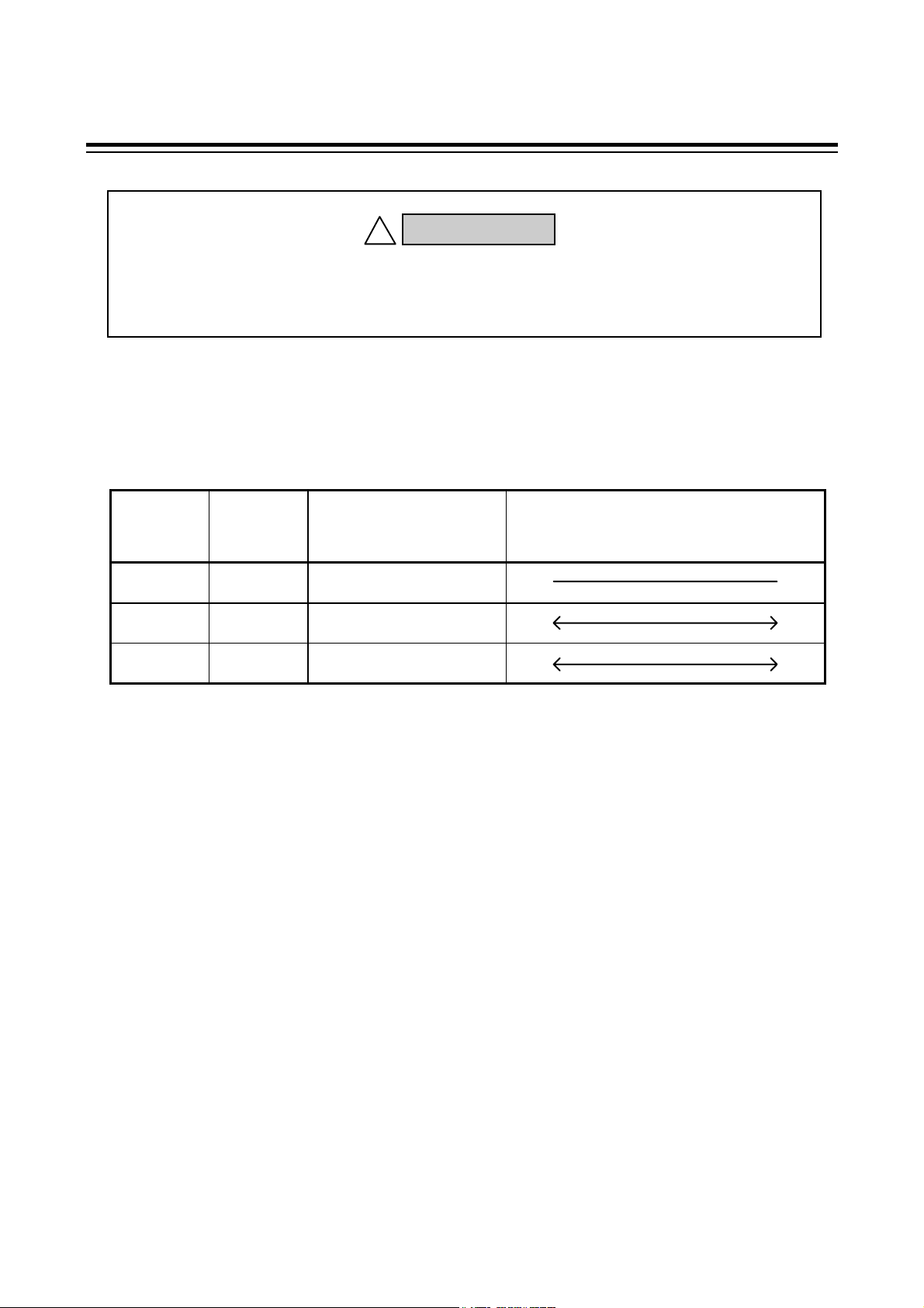
(1) Terminal No. and signal details
Terminal
No.
7 SG Signal ground
8 T/R(A) Send data/Receive data
9 T/R(B) Send data/Receive data
Signal
name
Name
Signal direction
REX-F9000 Host computer
or PLC
IM9000F02-E3
3
Page 10
2. CONNECTION
(B)
(A)
(B)
(A)
)
)
p
(B)
(A)
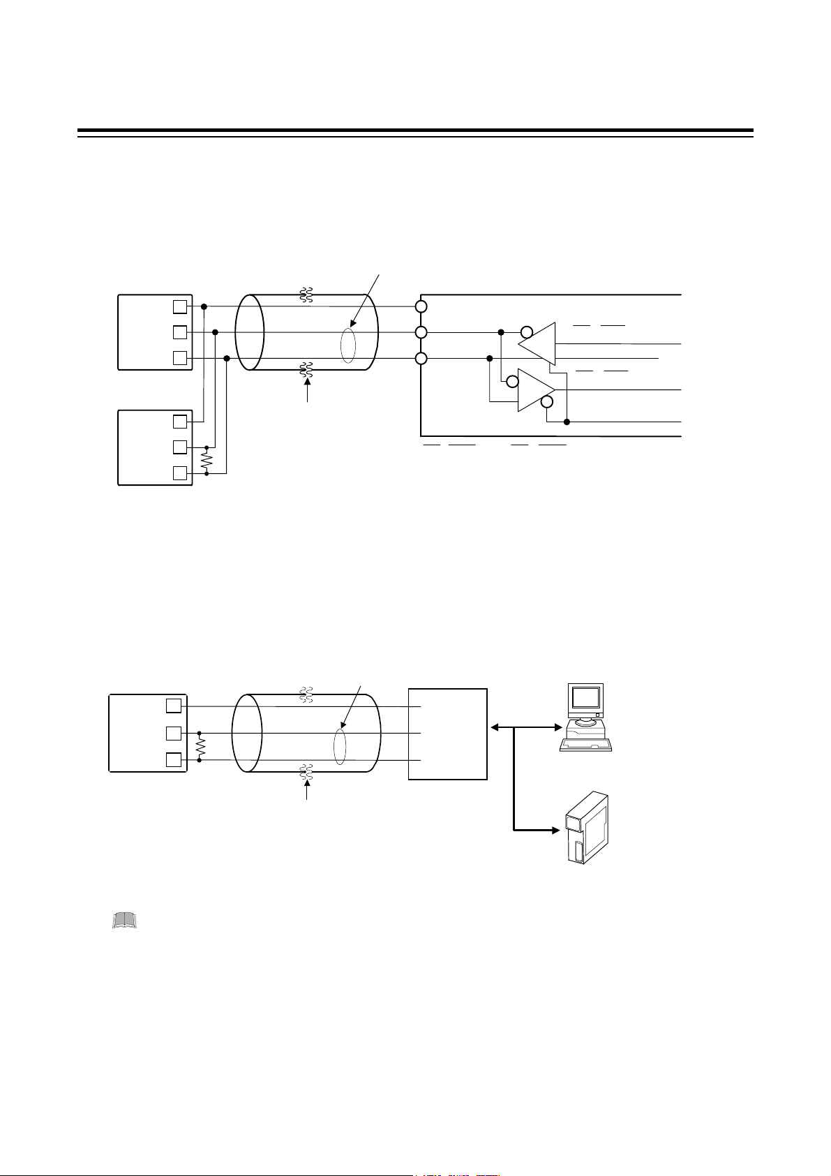
(2) Connecting method
When RS-485 is used as a host computer or PLC interface
It is necessary that a circuit to transfer send and receive be built-in the host computer (or PLC).
REX-F9000
SG
T/R
T/R
REX-F9000
SG
T/R
T/R
Up to 31
RS-485
7
8
9
7
8
9
*R
Twisted pair wire
(with shield)
Paired wire
Host com
uter or PLC
SG
T/R
T/R
SD (TXD
RD (RXD
Send/receive
selection signal
SD (TXD) and RD (RXD): Negative logic
*R: Termination resistors (Example: 120 Ω 1/2 W)
When RS-232C is used as a host computer or PLC interface
Communication level converter (RS-232C/RS-485) is used.
REX-F9000
SG
T/R(A)
Paired
7
8
RS-485
wire
Communication
level converter
SG
T/R(A)
Host computer
RS-232C
or
Send data
:
Receive data
:
T/R(B)
*R: Termination resistors (Example: 120 Ω 1/2 W)
9
*R
Twisted pair wire
(with shield)
When the host computer is for Windows 95/NT, use a communication level converter
of the automatic send/receive select type.
Recommended: CD485, CD485/V manufactured by Data Link, Inc. or equivalent.
4
T/R(B)
PLC communication
module
IM9000F02-E3
Page 11
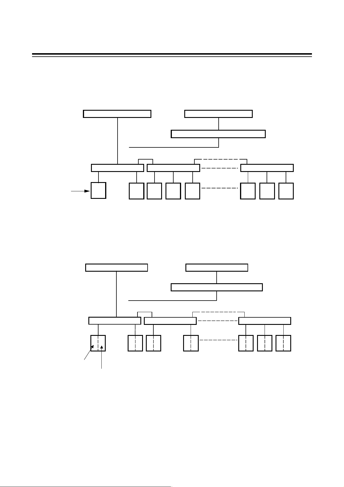
(3) Connection example
1-channel type
When up to 32 REX-F9000 controllers including host computer (or PLC) are connected.
2. CONNECTION
Device
address
2-channel type
Host computer or PLC
RS-485
Junction terminal
0
REX-F9000
or
Junction terminal
1
2
REX-F9000
Host computer or PLC
RS-232C
Communication level converter
RS-485
RS-485
3
4
Junction terminal
29
28
REX-F9000
30
For the 2-channel type REX-F9000 controller, set independent device addresses to CH1 and CH2.
Host computer or PLC
RS-485
or
Host computer or PLC
RS-232C
Communication level converter
RS-485
Device address for CH1
Device address for CH2
IM9000F02-E3
Junction terminal
1 0
REX-F9000
Junction terminal Junction terminal
3 2
5 4
REX-F9000
RS-485
7 6
57
59
56
REX-F9000
58
60
61
5
Page 12
3. SETTING FOR COMMUNICATION
In order to make communication between the REX-F9000 and the host computer (or PLC), it is
necessary to set the device address, communication speed, communication data configuration, interval
time and protocol. Communication settings are made in parameter group 24 (PG24).
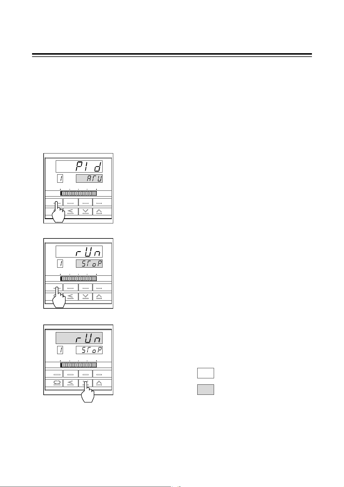
3.1 Preparation for Setting Communication Parameters
The setting of parameter group 24 (PG24) can be changed only in control stop mode. Before the
SETUP mode is selected, it is necessary to set the mode selection of "Control RUN/STOP" to
"STOP."
PV
CH
MODE
PV
CH
MODE MONI CH
SV
MONI CH
SET
SV
SET
1. Press the MODE key to set the instrument to the mode transfer.
2. Press the MODE key to display "Control RUN/STOP."
PV
3. Press the DOWN key to control is changed from execution
(RUN) to STOP.
CH
MODE MONI CH
SV
: Bright lighting
SET
: Dim lighting
6
IM9000F02-E3
Page 13
3. SETTING FOR COMMUNICATION
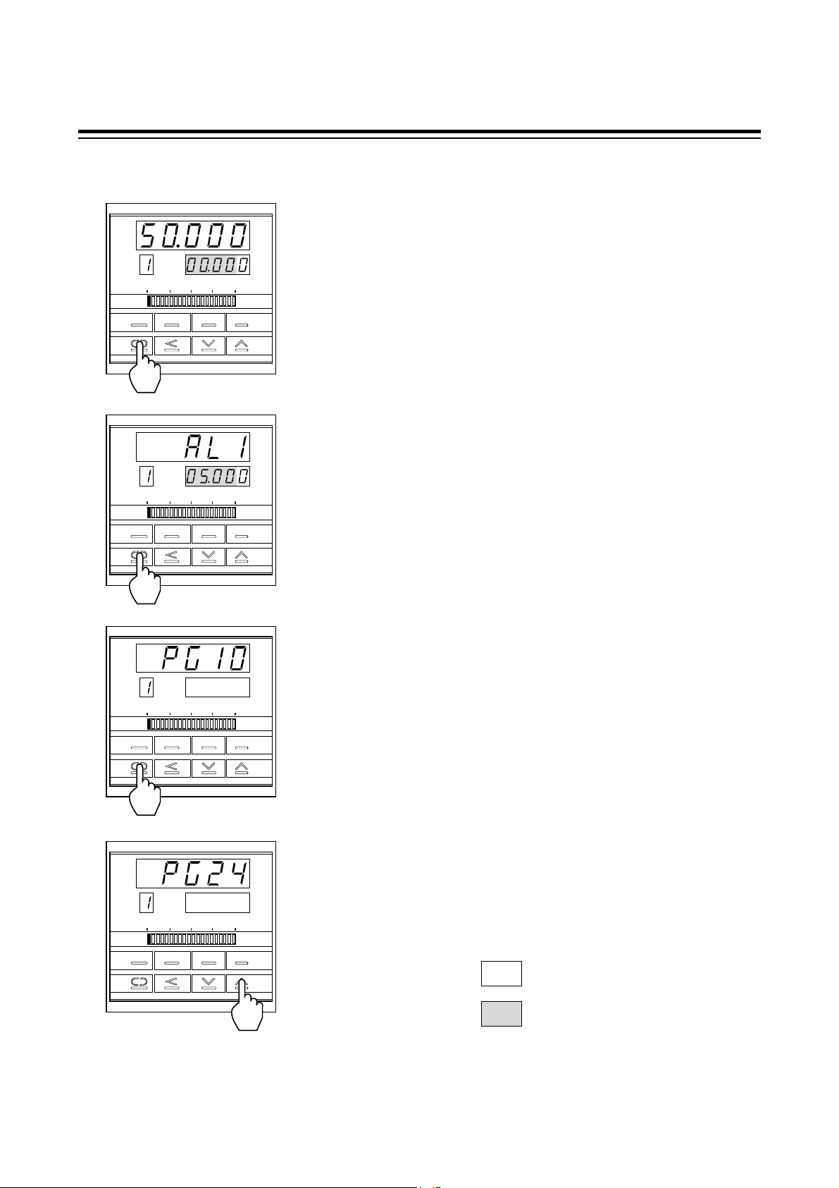
3.2 Transfer to Parameter Group 24 (PG24)
PV
CH
MODE MONI CH
PV
CH
MODE MONI CH
SV
SET
SV
SET
1. Press the SET key to set the instrument to the SV setting mode.
2. Press the SET key for more than 5 sec in SV setting mode to set
the instrument to operator set mode.
PV
CH
MODE MONI CH
PV
CH
MODE MONI CH
SV
SET
SV
SET
3. Press the SET key for more than 5 sec in operator set mode to
set the instrument to setup mode.
4. Press the UP key a few times to display "PG24."
: Bright lighting
: Dim lighting
IM9000F02-E3
7
Page 14

3. SETTING FOR COMMUNICATION
3.3 Communication Parameter Selection
Communication parameter in parameter group 24 (PG24) are selected in the order of device address
(Add), communication speed (bPS), communication data configuration (bIT), interval time (InT) and
protocol selection (CMPS). Each communication parameter is selected by pressing the SET key.
Display sequence
PV
Parameter group 24
CH
SV
(PG24)
Press the SET key.
PV
Device address
CH
SV
(Add)
Press the SET key.
PV
Communication speed
CH
SV
(bPS)
Press the SET key.
PV
Data configuration
CH
SV
(bIT)
In order to set the CH2 monitor,
communication parameter, press
the CH key to change CH1 to
CH2. The setting procedure is
Press the SET key.
PV
the same as the CH1 setting.
CH
SV
(InT)
Press the SET key.
Interval time
PV
Protocol selection
CH
SV
(CMPS)
Press the SET key.
8
IM9000F02-E3
Page 15
3. SETTING FOR COMMUNICATION
(
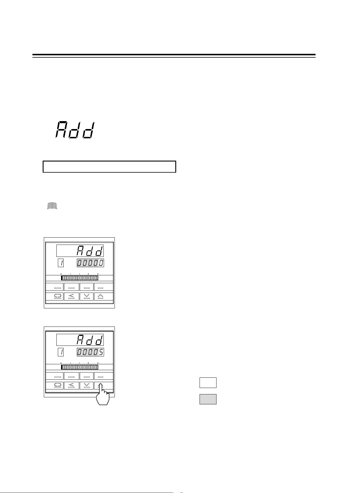
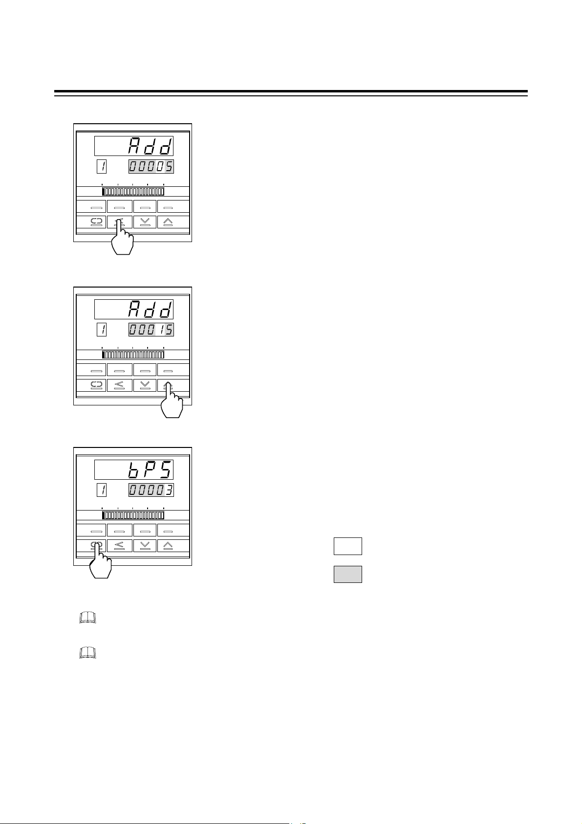
3.4 Device Address Setting
Set the desired device address by using the corresponding numeric value from 0 to 99.
Press the UP or DOWN key to change the numeral, and also press the SHIFT key to shift the digit.
Symbol and symbol name
Add) : Device address
Setting range
Range: 0 to 99 Factory set value: 0
Setting procedure
For the 2-channel type REX-F9000, set independent device addresses to CH1 and CH2.
Example: When setting device address to 15.
PV
1. Change the controller to parameter group 24 (PG24), and then
display the device address (See P. 8).
CH
MODE MONI C H
PV
SV
SET
2. Set the devise address. Press the UP key to enter "5" in the
lowest
CH
SV
digit.
MODE MONI C H
SET
: Bright lighting
: Dim lighting
IM9000F02-E3
9
Page 16
3. SETTING FOR COMMUNICATION
PV
CH
MODE MONI C H
PV
CH
MODE MONI C H
SV
SET
SV
SET
3. Press the SHIFT key to brightly light the tens digit.
4. Press the UP key to enter "1" in the tens digit.
PV
5. Press the SET key to select the next communication parameter.
As a result, the set device address is registered.
CH
MODE MONI C H
SV
SET
: Bright lighting
: Dim lighting
For the 1-channel type, if the key is not operated for more than 1 minute, the present display
automatically returns to the PV/SV display.
For the 2-channel type, if the key is not operated for more than 1 minute, the present display
automatically returns to the CH1PV/CH2PV display.
10
IM9000F02-E3
Page 17
3. SETTING FOR COMMUNICATION
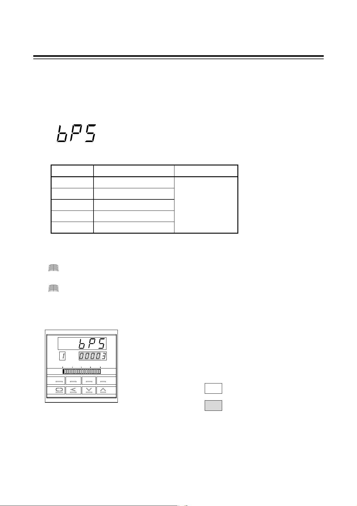
3.5 Communication Speed Setting
Set a communication speed of 1200 bps, 2400 bps, 4800 bps, 9600 bps or 19200 bps by using
numerals from 0 to 4. Press the UP or DOWN key to change the numeral.
Symbol and symbol name
(bPS) : Communication speed
Setting items
Set value Communication speed Factory set value
0 1200 bps
1 2400 bps
2 4800 bps 3
3 9600 bps
4 19200 bps
Setting procedure
Set the same communication speed to both the REX-F9000 and connecting host
computer (or PLC).
For the 2-channel type REX-F9000, set the same communication speed to CH1 and
CH2.
Example: When setting communication speed to "2: 4800 bps."
PV
CH
SV
1. Select the communication speed display. (See P. 8.)
MODE MONI C H
SET
IM9000F02-E3
: Bright lighting
: Dim lighting
11
Page 18

3. SETTING FOR COMMUNICATION
PV
CH
MODE MONI C H
PV
CH
MOD MONI C H
SV
SET
SV
SET
2. Press the DOWN key to enter "2" in the lowest digit. As a
result, a communication speed of 4800 bps is set.
3. Press the SET key to change to the next communication
parameter. As a result, the set communication speed is
registered.
: Bright lighting
: Dim lighting
For the 1-channel type, if the key is not operated for more than 1 minute, the present display
automatically returns to the PV/SV display.
For the 2-channel type, if the key is not operated for more than 1 minute, the present display
automatically returns to the CH1PV/CH2PV display.
12
IM9000F02-E3
Page 19

3. SETTING FOR COMMUNICATION
3.6 Communication Data Configuration Setting
Set the data configuration during communication. Press the UP or DOWN key to change the numeral.
Symbol and symbol name
(bIT) : Communication data configuration
Setting items
(1) RKC standard communication: Set the desired numeric value from 0 to 11.
Set value Parity bit Data bit Stop bit Factory set value
0 None 8 1
1 None 8 2
2Even 8 1
3Even 8 2
4Odd 8 1
5 Odd 8 2 0
6 None 7 1
7 None 7 2
8Even 7 1
9Even 7 2
10 Odd 7 1
11 Odd 7 2
(2) Ladder communication: The following numeric value is fixed.
Parity bit: None
Data bit: 8
Stop bit: 1
IM9000F02-E3
If the protocol is for ladder communication, it becomes invalid even when the
communication data bit configuration is selected.
13
Page 20

3. SETTING FOR COMMUNICATION
Setting procedure
For the 2-channel type REX-F9000, set the same communication data configuration to
CH1 and CH2.
Example: When setting communication data configuration to "1: 8 data bits, no parity bit and
2 stop bits."
PV
CH
MODE MONI CH
SET
PV
CH
MODE MONI CH
SET
SV
SV
1. Select the data configuration during communication. (See P. 8.)
2. Press the UP key to enter "1" in the lowest digit. As a result,
communication data configuration is set to "8 data bits, no
parity bit and 2 stop bits."
14
PV
CH
SV
parameter. As a result, the set communication data
configuration is registered.
: Bright lighting
3. Press the SET key to change to the next communication
MODE MONI CH
SET
: Dim lighting
For the 1-channel type, if the key is not operated for more than 1 minute, the present display
automatically returns to the PV/SV display.
For the 2-channel type, if the key is not operated for more than 1 minute, the present display
automatically returns to the CH1PV/CH2PV display.
IM9000F02-E3
Page 21

3. SETTING FOR COMMUNICATION
3.7 Interval Time Setting
Set the interval time. Press the UP or DOWN key to change the numeral, and press the SHIFT key to
shift the digit.
Symbol and symbol name
(InT) : Interval time
Setting range
Range: 0 to 250 ms Factory set value: 250
Setting procedure
For the 2-channel type REX-F9000, set the same interval time to CH1 and CH2.
Example: When setting interval time to 200 ms.
PV
CH
MODE MONI C H
SET
PV
CH
SV
SV
1. Select the interval time display. (See P. 8.)
2. Press the SHIFT key to brightly light the tens digit.
MODE MONI CH
SET
IM9000F02-E3
: Bright lighting
: Dim lighting
15
Page 22

3. SETTING FOR COMMUNICATION
PV
CH
MODE MONI C H
PV
CH
MODE MONI C H
SV
SET
SV
SET
3. Press the DOWN key to enter "0" in the tens digit.
4. Press the SET key to change to the next communication
parameter. As a result, the set interval time is registered.
: Bright lighting
: Dim lighting
For the 1-channel type, if the key is not operated for more than 1 minute, the present display
automatically returns to the PV/SV display.
For the 2-channel type, if the key is not operated for more than 1 minute, the present display
automatically returns to the CH1PV/CH2PV display.
16
IM9000F02-E3
Page 23

3. SETTING FOR COMMUNICATION
3.8 Protocol Setting
The protocol is selected. Either RKC standard communication or ladder communication is
selected.
Press the UP or DOWN key to change the numeral.
Symbol and symbol name
(CMPS) : Protocol selection
Setting items
Set value Protocol type Factory set value
0 RKC standard communication 0
1 Ladder communication
Setting procedure
For the 2-channel type REX-F9000, set the same protocol selection to CH1 and CH2.
Example: When setting protocol to "1: Ladder communication."
PV
CH
MODE MONI CH
SET
SV
1. Select the protocol selection display. (See P. 8.)
: Bright lighting
: Dim lighting
PV
CH
MODE MONI CH
SET
IM9000F02-E3
2. Setting a numeric value of "1" by pressing the UP key changes
the protocol to ladder communication.
SV
17
Page 24

3. SETTING FOR COMMUNICATION
PV
CH
MODE MONI CH
SET
SV
parameter. As a result, the set data construction is registered.
: Bright lighting
: Dim lighting
For the 1-channel type, if the key is not operated for more than 1 minute, the present display
automatically returns to the PV/SV display.
For the 2-channel type, if the key is not operated for more than 1 minute, the present display
automatically returns to the CH1PV/CH2PV display.
3. Press the SET key to change to the next communication
18
IM9000F02-E3
Page 25

3. SETTING FOR COMMUNICATION
3.9 Cautions for Communication
(1) Send/receive selection
When host computer is selected from data sending to data receiving
When switching the host computer into reception from transmission, it must be confirmed that the
data was surely put on line. This is not observe the transmission buffer of host computer itself, but
confirming with shift register.
Next, the REX-F9000 side secures the maximum time until the transmission line changes to the data
receiving side (until the REX-F9000 is ready to send data) after the host computer has received the
stop bit corresponding to the final character. This maximum time corresponds to interval time. If no
interval time is set, the REX-F9000 side may be set to the send state even when the host computer
side is not set to the receive state. As a result, no communication is conducted correctly. In addition,
set the interval time so as to match the host computer.
When host computer is selected from data receiving to data sending
Polling procedure "Response wait time after BCC send" or selecting procedure "Response wait time
after [ACK] or [NAK] send" is processing time required during REX-F9000 data sending. Therefore,
select the host computer from receiving to sending after the lapse of the above time. As for the
necessary processing time, refer to the table of page 21.
IM9000F02-E3
19
Page 26

3. SETTING FOR COMMUNICATION
(2) RS-485 (2-wire system) send/receive timing
The transmission and reception of RS-485 communication are operated by a transmitting wire.
Therefore, the timing of switching should be acted correctly. Send/receive example in the host
computer and REX-F9000 is show in the following.
Polling procedure
Host computer
REX-F9000
Send data
(Possible/Impossible)
Sending status
Send data
(Possible/Impossible)
Sending status
Possible
Imposs ible
Possible
Imposs ible
E
O
T
- - - - - -
E
N
Q
a.
S
T
X
- - - - - -
b.
B
C
C
a. (Response send time after calling [ENQ] receive) + (Interval time)
b. Response send time after BCC send
c. (Response send time after acknowledgment [ACK] receive) + (Interval time) or
(Response send time after negative acknowledge [NAK] receive) + (Interval time)
Selecting procedure
Host computer
REX-F9000
Send data
(Possible/Impossible)
Sending status
Send data
(Possible/Impossible)
Sending status
Possible
Impos sible
Possible
Impos sible
S
T
X
- - - - - -
B
C
C
a.
b.
A
or
C
K
N
A
or
A
C
K
K
c.
N
A
K
a. (Response send time after BCC receive) + (Interval time)
b. Response wait time after acknowledgment [ACK] send or
Response wait time after negative acknowledge [NAK] send
To switch the host computer from transmission to reception, send data must be on line. To
check if data is on line, do not use the host computer’s transmission buffer but confirm it by
the shift register.
Polling procedure "Response wait time after BCC send" or selecting procedure "Response
wait time after [ACK] or [NAK] send" is processing time required during REX-F9000 data
sending. Therefore, select the host computer from receiving to sending after the lapse of the
above time.
20
IM9000F02-E3
Page 27

3. SETTING FOR COMMUNICATION
(3) RS-422A/RS-485 Fail-safe
A transmission error may occur with the transmission line disconnected, shorted or set to the highimpedance state. In order to prevent the above error, it is recommended that the fail-safe function be
provided on the receiver side of the host computer. The fail-safe function can prevent a framing error
from its occurrence by making the receiver output stable to the MARK (1) when the transmission line
is in the high-impedance state.
(4) Send/receive processing times
The processing time shown in the following is required for the REX-F9000 during data sending and
receiving.
Polling procedure
Procedure details Time (ms)
MIN TYP MAX
Response send time after calling [ENQ] receive
Response send time after acknowledgment [ACK] receive
Response send time after negative acknowledge [NAK] receive
Response send time after BCC send
Data link is terminated sending [EOT], if no response within about 3 sec after BCC send.
Response wait time is the time when the interval time is set to 0 ms.
Selecting procedure
Procedure details Time (ms)
Response send time after BCC receive 2.0 3.0 7.0
Response wait time after acknowledgment [ACK] send
Response wait time after negative acknowledge [NAK] send
MIN TYP MAX
7.0
7.0
7.0
1.0
1.0
1.0
IM9000F02-E3
Response wait time is the time when the interval time is set to 0 ms.
21
Page 28

4. RKC STANDARD COMMUNICATION
p
[
]
[
]
[
]
[
]
[
]
A
A
Q
4.1 Communication Protocol
The REX-F9000 uses the polling/selecting method to establish a data link. The basic procedure is
followed ANSI X3.28 subcategory 2.5, A4 basic mode data transmission control procedure (Fast
selecting is established for selecting).
• In the polling/selecting method, the REX-F9000 is controlled completely by the host computer is
permitted. Since the host computer invites information message sending from and receiving to the
REX-F9000, send the data in accordance with the polling or selecting procedure. (Centralized
control method)
• The code use in communication is 7-bit ASCII code including transmission control character. The
transmission control characters are [EOT] (04H), [ENQ] (05H), [ACK] (06H), [NAK] (15H), [STX]
(02H) and [ETX] (03H). The figure in the parenthesis is indicating hexadecimal number.
4.1.1 Polling
Polling is an action that host computer requesting one of the REX-F9000 which selected among
multidrop connected, to transmit the data. The procedure is as the following.
E
O
T
(1)
Host com
Address
uter send
ID
(2)
Host
REX-F9000 send
E
N
No response
computer
send
REX-F9000
send
(5)
E
O
T
(4)
(3)
E
T
X
BCC
(8)
No
response
Time
out
S
ID
T
X
Data
(9)
Indefinite
Host
computer
send
E
O
T
(10)
E
O
T
(6)
C
K
N
K
(7)
ID: Identifier
22
IM9000F02-E3
Page 29

4. RKC STANDARD COMMUNICATION
Polling procedure
(1) Initialize of data link
Host computer sends [EOT] for initializing of data link before polling sequence.
(2) Polling sequence send
Host computer sends polling sequence with a format shown below.
Example:
ENQ
1
M02
Device
address
2. 3.1.
ENQ
Identifier
1. Device address [Number of digits: 2]
This data is a device address of the REX-F9000 for polled and must be the same as the device
address set value in item "3.4 Device address setting" (P. 9).
2. Identifier [Number of digits: 2] (See P. 31)
This is for identifying data requested for the REX-F9000.
Always attach the [ENQ] code to the end of the identifier.
3. [ENQ]
This is the transmission control character which indicates the end of the polling sequence. Then,
the host computer waits for response from the REX-F9000.
(3) REX-F9000 data send
If the polling sequence is received correctly, the REX-F9000 sends data in the following format.
STX Identifier
1. [STX]
This is the transmission control character which indicates the start of the text (identifier and
data).
IM9000F02-E3
1. 2. 3. 4. 5.
Data
ETX BCC
23
Page 30

4. RKC STANDARD COMMUNICATION
2. Identifier [Number of digits: 2] (See P. 31)
This is for identifying data (measured value, status and set value) sent to the host computer.
3. Data [Number of digits: 7]
Data indicated by the identifier belonging to the REX-F9000. It is expressed in decimal ASCII
code including a minus sing (−) and a decimal point. No zero suppression is made.
4. [ETX]
A transmission control character used to indicate text end.
5. [BCC]
BCC (Block Check Character) for error detection using horizontal parity. BCC is calculated by
horizontal parity (even number).
<Algorithm>
Take off exclusive "OR" of all character from next [STX] through [ETX].
Not including [STX].
Example:
In the case of the data are:
S
T
X
E
BCC
T
000.3201M
X
50H31H 03H30H30H30H2EH33H32H30H4DH
In the parenthesis are
indicated with hexadecimal
number.
BCC = 4DH ⊕ 31H ⊕ 30H ⊕ 32H ⊕ 33H ⊕ 2EH ⊕ 30H ⊕ 30H ⊕ 30H ⊕ 03H = 50H
Value of BCC becomes 50H
(4) REX-F9000 data send end (EOT send)
If the following cases, the REX-F9000 sends [EOT] to terminate the data link.
• When there is no specified identifier.
• When there is an error in the data type.
• After all the data has been sent.
(5) REX-F9000 no response
The REX-F9000 is set to no response when the polling sequence is not received correctly. If
necessary, take time out recovery etc. for the host computer.
24
IM9000F02-E3
Page 31

4. RKC STANDARD COMMUNICATION
(6) Acknowledgment [ACK]
Send [ACK] when the host computer could receive data items correctly.
Next, the REX-F9000 sends the identifier data following the identifier just sent in succession shown
in " Communication identifier list" (P. 31).
If data send from the REX-F9000 is suspend, send [EOT] to terminate the data link.
(7) Negative acknowledge [NAK]
If the host computer cannot receive send data correctly from the REX-F9000, it sends [NAK] to the
controller. Then, the REX-F9000 re-sends the same data to the host computer.
As the number of re-send times is not specified, take the necessary measures on the host computer
side if no recovery is made.
(8) No response from host computer
When the host computer is set to no response after the REX-F9000 sends data, the REX-F9000 sends
[EOT] as time-out processing to terminate the data link (time-out time: approx. 3 sec).
(9) Indefinite response from host computer
When the response from the host computer is indefinite, the REX-F9000 sends [EOT] to terminate the
data link.
(10) Data link termination [EOT]
If it is necessary to suspend communication with the REX-F9000 or to terminate the data link due to
no response from the controller, the host computer sends [EOT].
IM9000F02-E3
25
Page 32

4. RKC STANDARD COMMUNICATION
Polling procedure example (When the host computer requests data)
Normal transmission
Host computer send
E
O
T
04H030H131HM4DH131H
IdentifierPolling
address
Host computer send
A
C
K
06H
S
T
X
02HA41HA41H030H030H030H030H030H030H030H
E
N
Q
05H
S
T
X
02HM4DH131H030H232H333H.2EH030H030H030H
REXF-9000 data send
Host computer send
E
O
04H
E
B
T
C
X
C
03H
33H
REX-F9000 data send
T
E
T
X
03H
B
C
C
50H
For the presence of error in data
Host computer send
E
O
T
04H
0
30H131H
M
4DH
1
31H
E
N
Q
05H
IdentifierPolling
address
N
A
K
15H
S
T
X
02HM4DH131H030H232H333H.2EH030H030H030H
REX-F9000 data send
S
T
M
X
02H
4DH131H030H232H333H.2EH
REX-F9000 data send
E
T
X
03H
Host computer sendHost computer send
B
C
C
50H
Error data
0
30H030H
A
C
K
06H
E
T
X
03H
B
C
C
50H
26
IM9000F02-E3
Page 33

4. RKC STANDARD COMMUNICATION
p
[
]
A
A
4.1.2 Selecting
Selecting is an operation in which the host computer selects one from among the REX-F9000s
multidrop connected and then of recommending data receive. The procedure is as the following.
Due to adopted fast selecting in REX-F9000s therefore becomes the type to send the data which
connected to selecting sequence.
Host
computer
send
E
O
T
(7)
E
O
T
(1)
Address
(2)
Host com
S
T
X
uter send
[ Identifier ]
[ Data ]
(3)
E
[ BCC ]
T
X
REX-F9000 send
No response
(6)
C
K
(4)
N
(5)
K
Selecting procedure
(1) Initialize of data link
Host computer sends [EOT] for initializing of data link before selecting sequence.
(2) Selecting address send
Send the selecting address selected as the selecting sequence from the host computer.
[Device address] (Number of digits: 2)
This data is a device address of the REX-F9000 to be selected and must be the same as the device
address set value in item "3.4 Device address setting" (P. 9).
IM9000F02-E3
27
Page 34

4. RKC STANDARD COMMUNICATION
(3) Data send
Host computer to send the data with a format indicated below continuing the selecting sequence.
STX Identifier Data ETX BCC
1. 2.
For [STX], [ETX] and [BCC], see item "4.1.1 Polling" (P. 22).
1. Identifier [Number of digits: 2] (See P. 31)
This identifies the data (set value) which is sent by the host computer.
2. Data [Number of digits: 7]
This is the data indicated by the identifier of the REX-F9000. It is expressed in decimal ASCII
code including a minus sign ( − ) and a decimal point. Even zero suppressed data or data whose
figures below the decimal point are omitted can be received (However, the maximum number of
digits is 7).
Example: When data is -1.5
−001.5 → Receivable −1.50 → Receivable
−01.5 → Receivable −1.500 → Receivable
−1.5 → Receivable
In addition, the REX-F9000 determines the receive data during selecting as follows.
Example: When setting data is between −10.00 to +10.00
When data is receivable: When data is not receivable:
−.5 → -0.5 − → Not receivable (NAK answer)
−.058 → -0.05 . → Not receivable (NAK answer)
.03 → 0.03 −. → Not receivable (NAK answer)
+0 → Not receivable (NAK answer)
(4) Acknowledgment [ACK]
If the REX-F9000 correctly received data sent from the host computer, send [ACK]. Then, if there
is data to be sent next on the host computer side, send the data.
After the data has been sent, send [EOT] to terminate the data link.
28
IM9000F02-E3
Page 35

4. RKC STANDARD COMMUNICATION
(5) Negative acknowledge [NAK]
The REX-F9000 sends [NAK] in the following cases. Then the appropriate recovery processing steps,
such as data resend on the host computer side should be taken.
• When an error occurs on the line (parity, framing error, etc.).
• When a BCC check error occurs.
• When there is no identifier.
• When receive data is not in the specified configuration
(Text is not in the "Identifier + data construction.")
• When the number of receive data digits exceeds 7.
• When normally receive data exceeds the setting range.
(6) No response
If the selecting address is not received correctly, the REX-F9000 is set to no response, if [STX],
[ETX] and [BCC] is not received correctly, the REX-F9000 is also set to no response.
(7) Data link termination [EOT]
When terminating the data link because there was no more to be sent on the host computer side or the
REX-F9000 was set to no response, send [EOT] from the host computer.
IM9000F02-E3
29
Page 36

4. RKC STANDARD COMMUNICATION
Selecting procedure example (When the host computer sends a set value)
Normal transmission
Host computer send
E
O
T
04H030H131H
address
S
T
X
02HS53H131H030H232H333H.2EH030H030H030H
Send dataSelecting
E
T
X
03H
B
C
C
4EH
A
C
K
06H
REX-F9000 send
Host computer send
S
T
X
02HP50H131H030H333H030H.2EH030H030H030H
Send data
For the presence of error in data
Host computer send
E
O
T
04H030H131H
address
S
S
T
X
02H
53H131H030H
Error data
E
B
T
C
X
C
03H
4FH
REX-F9000 send
3
33H.2EH030H030H030H
Send dataSelecting
A
C
K
06H
Host computer send
E
O
T
04H
30H232H
E
B
T
C
X
C
03H
4EH
REX-F9000 send
S
T
X
02H
......................0
N
A
K
15H
30
S
T
X
02HS53H131H030H232H333H.2EH030H030H030H
Resend data
E
T
X
03H
B
C
C
4EH
06H
REX-F9000 send
Host computer sendHost computer send
S
T
1 .....
X
02HA41H
31H
A
C
K
IM9000F02-E3
Page 37

4.2 Communication Identifier
Communication identifier list
Before changing data corresponding to the identifiers from "XI (input type)" to "WB
(alarm 2 hold action selection)," always turn the "Control RUN/STOP" mode to
"STOP."
The number of digits is 7 for all data. [Except for model code (ID)]
4. RKC STANDARD COMMUNICATION
(Attributes RO: Read only, R/W: Read/Write)
Name Iden-
Model code
Measured value (PV)
Alarm 1 output
Alarm 2 output
1
2
Manipulated output value
(MV)
Burnout
Error code
PID/AT transfer
AUTO/MANUAL
transfer
Control RUN/STOP
Data range Attribute Factory set
tifier
ID
M1
AA
AB
O1
0: OFF 1: ON RO
0: OFF 1: ON RO
−5.0 to +105.0 %
When the instrument is the
manual (MAN) mode, attribute
becomes results in Read/Write
(R/W).
B1
ER
G1
J1
0: OFF 1: ON RO
0 to 255 See Table 1 (P. 34) RO
0: PID 1: Autotuning (AT) R/W 0
0: AUTO
1: MANUAL
SR
0: RUN 1: STOP R/W 0
value
RO
RO
RO
R/W 0
Set value (SV)
Alarm 1 setting
Alarm 2 setting
Proportional band
Integral time
Derivative time
IM9000F02-E3
S1
A1
A2
P1
I1
D1
Setting limiter (low limit) to
setting limiter (high limit)
Process alarm:
0.000 to 50.000 °C
Deviation alarm:
−19.999 to +19.999 °C
0.001 to 50.000 °C
(0.000 can't be set.)
0.1 to 3600.0 seconds
(0.0 can't be set.)
0.0 to 3600.0 seconds
0.0: Derivative action OFF
R/W 0.000
R/W 5.000
R/W 30.000
R/W 240.0
R/W 60.0
Continued on the next page.
31
Page 38

4. RKC STANDARD COMMUNICATION
Continued from the previous page.
(Attributes RO: Read only, R/W: Read/Write)
Name Iden-
Control response parameter
PV bias
Sensor bias
Digital filter
Output limiter (high limit)
Output limiter (low limit)
AT bias
Alarm 1 differential gap
Alarm 1 timer setting
Alarm 2 differential gap
Alarm 2 timer setting
1
1
2
2
tifier
CA
PB
PC
F1
OH
OL
GB
HA
TD
HB
TG
Data range Attribute Factory set
value
0: Slow
R/W 0
1: Medium
2: Fast
−19.999 to +19.999 °C R/W 0.000
−1.9999 to +1.9999 Ω R/W 0.0000
0.0 to 100.0 seconds
R/W 0.0
0.0: Digital filter OFF
Output limiter (low limit) to
R/W 100.0
+105.0 %
−5.0 % to
R/W 0.0
output limiter (high limit)
−19.999 to +19.999 °C R/W 0.000
0.000 to 50.000 °C R/W 2.000
0 to 600 seconds R/W 0
0.000 to 50.000 °C R/W 2.000
0 to 600 seconds R/W 0
Analog output specification
selection
Analog output scale high
Analog output scale low
3, 4
3
3
Bar-graph display selection
Input type
LA
HV
HW
DA
XI
0: Measured value (PV)
R/W 0
1: Deviation (DEV)
2: Set value (SV)
4: Manipulated output value (MV)
See Table 2 (P. 34) R/W 50.000
R/W 0.000
0: Manipulated output value(MV)
R/W 0
[1 dot: 5 %]
1: Deviation (DEV)
[0.01 °C/dot]
2: Deviation (DEV)
[0.1 °C/dot]
0: Pt100 Ω (3-wire system)
R/W
5
0
1: Pt100 Ω (4-wire system)
2: JPt100 Ω (3-wire system)
3: JPt100 Ω (4-wire system)
Continued on the next page.
32
IM9000F02-E3
Page 39

Continued from the previous page.
4. RKC STANDARD COMMUNICATION
(Attributes RO: Read only, R/W: Read/Write)
Name
Decimal point position
selection
Power supply frequency
Setting limiter (high limit)
Setting limiter (low limit)
Output cycle time
Direct/reverse action
selection
Power feed forward
7
Alarm 1 type selection
Alarm 1 energize/deenergize selection
Alarm 1 action selection at
abnormality
Alarm 1 hold action
selection
Alarm 2 type selection
Alarm 2 energize/deenergize selection
Alarm 2 action selection at
abnormality
Alarm 2 hold action
selection
Iden-
tifier
XU
JT
SH
SL
T0
XE
PF
XA
NA
OA
WA
XB
NB
OB
WB
Data range Attribute
0: No digit below decimal-point
R/W
1: 1 digit below decimal-point
2: 2 digits below decimal-point
3: 3 digits below decimal-point
0: 50 Hz
R/W
1: 60 Hz
2: Auto setting
Setting limiter (low limit) to
6
R/W
50.000 °C
0.000 °C to
R/W
setting limiter (high limit)
0.1 to 100.0 seconds R/W
0: Direct action
R/W
1: Reverse action
0: OFF 1: ON R/W
See Table 3 (P. 35) R/W
0: Energize
R/W
1: De-energize
0: Normal action
R/W
1: Forced alarm output ON
See Table 4 (P. 35) R/W
See Table 3 (P. 35) R/W
0: Energize
R/W
1: De-energize
0 : Normal action
R/W
1 : Forced alarm output ON
See Table 4 (P. 35) R/W
5
5
5
5
5
5
5
5
5
5
5
5
5
5
5
Factory set
value
3
0
50.000
0.000
0.1
1
1
0
0
0
0
0
0
0
0
Set data lock level selection
Mode lock level selection
1
This is an identifier which enables communication when there is an alarm 1.
2
This is an identifier which enables communication when there is an alarm 2.
IM9000F02-E3
LK
LM
See Table 5 (P. 35) R/W 0
See Table 6 (P. 35) R/W 0
Continued on the next page.
33
Page 40

4. RKC STANDARD COMMUNICATION
3
This is an identifier which enables communication when there is an analog output.
4
The analog output specification selection must not set 3.
5
Data can be written only in STOP mode.
6
Set the auto setting when the power feed forward function is used. When no power feed input is used,
set the desired power frequency (0: 50 Hz or 1: 60 Hz).
When "2: Auto setting" is selected, control stops under the following condition.
•••• When no power feed input is used (no power feed transformer is connected)
•••• When power feed input voltage becomes less than 30 % of rated value
7
When the power feed forward function is used, the power feed input is required from the power feed
transformer. When no power feed input is used, always set the power feed forward function to
"0: OFF."
When the power feed forward function is set to "1: ON," control stops under the
following condition.
•••• When no power feed input is used (no power feed transformer is connected)
•••• When power feed input voltage becomes less than 30 % of rated value
Table 1: Error code
Any number other than "0" indicates errors (RAM write error, etc.) detected by the REX-F9000 selfdiagnosis function. If two or more errors occur simultaneously, the sum total of all error Nos. is sent.
Contact your nearest RKC sales agent or RKC sales office.
Error code Details
MCU abnormality
MCU power supply voltage abnormality
Software abnormality
16 Input circuit abnormality
8 EEPROM error
4 Adjusted data destruction
2 Sensor break
1 Other abnormality
Table 2: Analog scale range
The analog output scale differs depending on the analog output specification.
Analog output specification Analog output scale range
0: When measured value (PV) is selected. 0.000 to 50.000 °C
1: When deviation (DEV) is selected. −19.999 to +19.999 °C
2: When set value (SV) is selected. 0.000 to 50.000 °C
3: When manipulated output (MV) is selected. −5.0 to +105.0%
34
IM9000F02-E3
Page 41

Table 3: Alarm type
Set value Type
0 No alarm
1 Set value high alarm
2 Set value low alarm
3 Process high alarm
4 Process low alarm
5 Deviation high alarm
6 Deviation low alarm
7 Deviation high/low alarm (Absolute value setting)
8 Band alarm (Absolute value setting)
4. RKC STANDARD COMMUNICATION
Table 4: Hold action type
Set value Type
0 No hold action
1 Hold action is taken when the power is turned on.
2 Hold action is taken when the power is turned on or the setting changed.
Table 5: Set data lock level
Set value Set data lock level
0 Set value (SV) and parameter can't be set.
1 Only set value (SV) can be set.
2 Only parameter group (PG) can't be set.
Table 6: Mode lock level
Set value PID/AT AUTO/MANUAL Control RUN/STOP
0 ×××
1 ××
2 × ×
3 ×
4 ××
5 ×
6 ×
7
IM9000F02-E3
: Unsettable (Mode lock)
×: Settable (Mode unlock)
35
Page 42

5. LADDER COMMUNICATION
5.1 Communication Protocol
Ladder communication is a communication means provided for connecting with the PLC. The REXF9000 uses the ignored process for the ladder communication protocol.
Definition of protocol
Read: Based on a data request from the PLC, data is sent to the PLC from the REX-F9000.
Write: Based on a data request from the PLC, data is received by the REX-F9000.
5.1.1 Communication data configuration
PLC →→→→ REX-F9000 (During data send from PLC)
1. 2. 3. 4. 5. 6. 7.
Number of
bytes
Number of
BCD digits
11 2 2211
22 4 4422
Details
REX-F9000 →→→→ PLC (During data receive by PLC)
Number of
bytes
Number of
BCD digits
Details
1. STX
This is the transmission control character which indicates the start of the text (identifier and
data). Set to STX (02H) fixed.
2. ADR [Device address]
This data corresponds to the device address to select one REX-F9000 from among many REXF9000s to which the PLC is multi-drop-connected. This should be the same as the device address
set value in "3.4 Device address setting" (P. 9).
STX
(02H)
1. 2. 3. 4. 5. 4. 5. 6. 7.
1 1 22222 1 1
2 2 44444 2 2
STX
(02H)
ADR ID CMD DAT CR
(0DH)LF(0AH)
......
......
ADR ID CMD DAT CMD DAT CR
......
(0DH)LF(0AH)
36
IM9000F02-E3
Page 43

5. LADDER COMMUNICATION
3. ID [Identifier]
These are numbers used for the PLC to identify data to be requested or set to the REX-F9000.
These are numbers of four figures in the communication identifier list (P. 44).
4. CMD [Command]
These are commands used for the PLC to identify the details of processing and the data sing to
be requested to the REX-F9000.
PLC → REX-F9000 (During data send from PLC)
Command
Details Identifier transfer order
(CMD)
(0000)
0001
Read request
Upper byte → Lower byte
0010 Write request, write data + (Positive)
0011 Write request, write data − (Negative)
0100 Read request (Byte inversion)
1000 Write request, write data + (Positive) Lower byte → Upper byte
1100 Write request, write data − (Negative)
Other Usage inhibited
REX-F9000 → PLC (During data receive by PLC)
Command
Details Identifier transfer order
(CMD)
0000 Read response, read data + (Positive) Data transfer order is in
accordance with the command
from the PLC connected to the
REX-F9000.
0001 Read response, read data − (Negative) Upper byte → Lower byte
0010 Write response, write result data + (Positive)
0011 Write response, write result data − (Negative)
0100 Read response, read data − (Negative) Lower byte → Upper byte
1000 Read request, write result data + (Positive)
1100 Read request, write result data − (Negative)
Other Abnormal response
IM9000F02-E3
37
Page 44

5. LADDER COMMUNICATION
5. DAT [Data]
Details of processing
by PLC
Polling
(For data read) REX-F9000 → PLC Read data
Selecting
(For data write) REX-F9000 → PLC Data after write execution
6. 7. CR, LF [Delimit]
Control characters to indicate the end of a text. The REX-F9000 judges that the text ends if it
receives CR (0DH) and LF (0AH) in succession.
Communication direction Details of send/receive data
PLC → REX-F9000 Number of read data (Maximum 30)
(Data such as measured value (PV),
etc.)
PLC → REX-F9000 Write data
5.1.2 Data format
The data (DAT) format is expressed as internal data excluding the decimal point.
Example:
Data name Actual data Internal data
Manipulated output
value (MV)
Proportional band 0.001 to 50.000 0001 to 5000
PV bias −19.999 to +19.999 −1999 to +1999
Alarm 1 setting Process alarm: 0.000 to 50.000
−5.0 to +105.0 −0050 to +1050
Process alarm: 0000 to 5000
Deviation alarm: −19.999 to +19.999
Deviation alarm: −1999 to +1999
38
IM9000F02-E3
Page 45

5. LADDER COMMUNICATION
5.1.3 Data read
Reads identifiers requested from the PLC by the corresponding number of data items. A response
from REX-F9000 is returned as 4-digit BCD data excluding the sign data and decimal point. Number
of data which can be read at a time: 1 to 30.
PLC send data
Number of bytes 11 2 2 2 11
Number of BCD
digits
Details STX
22 4 4 4 22
Identifier
(ID)
(02H)
Device
address
(ADR)
REX-F9000 response under normal operation
Number of
bytes
Number of
BCD digits
Details STX
1122222
2244444
Identifier
(ID)
(02H)
Device
address
(ADR)
0001 Read
data
CR
(0DH)LF(0AH)
Command Data (DAT)
(CMD)
0000 dddd1 0000 dddd2
.....
.....
.....
IM9000F02-E3
This numeric value changes
depending on the data sign
Command Data (DAT) Data corresponding
(CMD) to identifier + 1
(+ or −). (0 or 1)
.....
.....
.....
2211
4422
0000 ddddn CR LF
Data corresponding to
identifier + n − 1 (n: Number of read data)
If there is no identifier requested by the PLC, the REX-F9000 returns the "0000" data.
39
Page 46

5. LADDER COMMUNICATION
5.1.4 Data write
Writes the specified data in the specified identifier. Write data is specified by 4-digit BCD data
excluding the sign data and decimal point.
The number of data which can be written at a time is 1.
PLC send data
Number of bytes 11 2 2 2 11
Number of BCD
digits
Details STX
22 4 4 4 22
dddd CR
(0DH)LF(0AH)
(02H)
Device
address
(ADR)
Identifier
(ID)
0010
or
0011
Command Setting data
(CMD)
REX-F9000 response
Number of bytes 11 2 2 2 11
Number of BCD
digits
Details STX Device
22 4 4 4 22
dddd CR LF
address
(ADR)
Identifier
(ID)
0010
or
0011
The original data is returned by ignoring data write for either of the following cases.
• The data range is exceeded, or
40
• a write inhibit identifier is specified.
IM9000F02-E3
Page 47

5. LADDER COMMUNICATION
5.1.5 Reversal of read/write data bytes
There are two methods of sending word data: One is to send the data from the upper byte and the
other is to send the data from the lower byte.
The following two items can be inverted: Identifier (ID) and data (DAT).
Only the data (DAT) can also be inverted by setting.
Number of bytes 11 2 2 2 11
Number of BCD
digits
Details STX
22 4 4 4 22
(02H)
Device
address
(ADR)
Identifier
(ID)
Command
(CMD)
These two items can be inverted.
Inverting method
Reversal of Identifier (ID) and data (DAT)
The usual data transfer order is reversed by the command (CMD).
PLC → REX-F9000 (During data send from PLC)
Command
Details Identifier transfer order
(CMD)
(0000)
Read request
0001
Data
(DAT)
CR
(0DH)LF(0AH)
Upper byte → Lower byte
0010 Write request, write data + (Positive)
0011 Write request, write data − (Negative)
0100 Read request (Byte inversion)
1000 Write request, write data + (Positive) Lower byte → Upper byte
1100 Write request, write data − (Negative)
Other Usage inhibited
IM9000F02-E3
Continued on the next page.
41
Page 48

5. LADDER COMMUNICATION
Continued from the previous page.
REX-F9000 → PLC (During data receive by PLC)
Command
Details Identifier transfer order
(CMD)
0000 Read response, Read data + (Positive) Data transfer order is in
0001 Read response, Read data − (Negative) Upper byte → Lower byte
0010 Write response, Write result data + (Positive)
0011 Write response, Write result data − (Negative)
accordance with the command
from the PLC connected to the
REX-F9000.
0100 Read response, Read data - (Negative) Lower byte → Upper byte
1000 Write request, Write result data + (Positive)
1100 Write request, Write result data − (Negative)
Other Abnormal response
Only data is inverted
Change can be made by specifying "0011" to the data number (ID) and setting data on "0: High
order→Low order " or "Other than 0: Low order→High order."
Number of bytes 11 2 2 2 11
Number of BCD
digits
Details STX
22 4 4 4 22
CR
(0DH)LF(0AH)
(02H)
Device
address
(ADR)
0011
Command
(CMD)
Set 0 or any
number other
than 0.
Identifier (ID) Data (DAT)
Example: The following procedure is executed for send/receive data of 1234h.
• When sending data from the upper byte
When REX-F9000 sends data: Sends data in order of 12h and 34h.
When REX-F9000 receives data: When REX-F9000 receives data in order of 12h and 34h, it
recognizes the data as 1234h.
• When sending data from the lower byte
When REX-F9000 sends data: Sends data in order of 34h and 12h.
When REX-F9000 receives data: When REX-F9000 receives data in order of 12h and 34h, it
recognizes the data as 3412h.
This setting is held even if the power is turned on again.
42
IM9000F02-E3
Page 49
5. LADDER COMMUNICATION
5.1.6 REX-F9000 no response
The REX-F9000 issues no-response for any of the following cases.
• The device address sent from the PLC does not match the device address of the REX-F9000.
• "CR" and "LF" can't be normally received.
• When there is an error in the data type.
• When a communication error occurs.
5.1.7 Example of text sent by PLC
Example of text
It is assumed that the address No. is 00 and that data notation is hexadecimal.
When reading measured value (PV)
PLC send
CommandDevice
address
Identifier
When writing set value (PV)
PLC send
Device
address
Command
Identifier
Number of
read data
Write data
LFCR00010000010000STX
LFCR00300010010500STX
REX-F9000 response
Device
address
REX-F9000 response
Device
address
Identifier
Measured value
Identifier
LFCR00230000010000STX
(PV)
LFCR00300010010500STX
Set value
(SV)
IM9000F02-E3
43
Page 50

5. LADDER COMMUNICATION
5.2 Communication Identifier
In RKC standard communication described above, each item is expressed by an identifier combined
with a number and a letter (M1, S1 ...) but in ladder communication, each item is expressed only by a
number.
(Attributes RO: Read only, R/W: Read/Write)
Item
Measured value
(PV)
Undefined
Manipulated
output value (MV)
Undefined
Alarm 1 output
Alarm 2 output
Burnout
(Measured value)
Set value (SV)
Alarm 1 setting
Alarm 2 setting
Identifier
Upper Lower
01 00
Details of data #1 #2 Factory
Within input range 1/100 °CRO
set value
01 01
01 02
−0050 to +1050 1/10 % RO
01 03
01 04
01 05
See Note 1 (P. 45)
Setting limiter (low limit) to
1/100 °C R/W 0000
RO
setting limiter (high limit)
01 06
Process alarm:
1/100 °C R/W 0500
0.000 to 50.000
01 07
Deviation alarm:
−19.999 to +19.999
Undefined
01 08
01 09
Proportional band
Undefined
Integral time
Derivative time
PID/AT transfer
AUTO/MANUAL
01 10
01 11
01 12
01 13
01 14
01 15
transfer
The amount of
01 16
manual output
#1: Engineering unit #2: Attribute
44
0001 to 5000 °C R/W 3000
0001 to 3600 second R/W 0240
0000 to 3600 second R/W 0060
0: PID
R/W 0000
1: Autotuning (AT)
0: AUTO
R/W 0000
1: MANUAL
Output limiter (low limit) to
1/10 % R/W
1
output limiter (high limit)
Continued on the next page.
IM9000F02-E3
Page 51
Continued from the previous page.
Item
Identifier
5. LADDER COMMUNICATION
(Attributes RO: Read only, R/W: Read/Write)
Details of data #1 #2 Factory
Upper Lower
PV bias
Undefined
Control
RUN/STOP
Reversing the
usual data transfer
2
order
01 17
01
to
01
18
to
99
00 00
00 11
−1999 to +1999 1/100 °C R/W 0000
0: RUN
1: STOP
0: Upper byte→Lower byte
Any number other than 0:
Lower byte→Upper byte
#1: Engineering unit #2: Attribute
Note 1: Details of the alarm 1 output, alarm 2 output and burnout
0 0 0 0
"0" Fixed
When burnout occurred = 1
When the alarm 2 occurred = 1
When the alarm 1 occurred = 1
set value
R/W 0000
R/W 0000
1
Data can be written only in manual mode.
2
Specified when only the data (DAT) block is inverted. If the inversion of transfer order is specified
by the command (CMD), this setting becomes invalid.
IM9000F02-E3
45
Page 52

5. LADDER COMMUNICATION
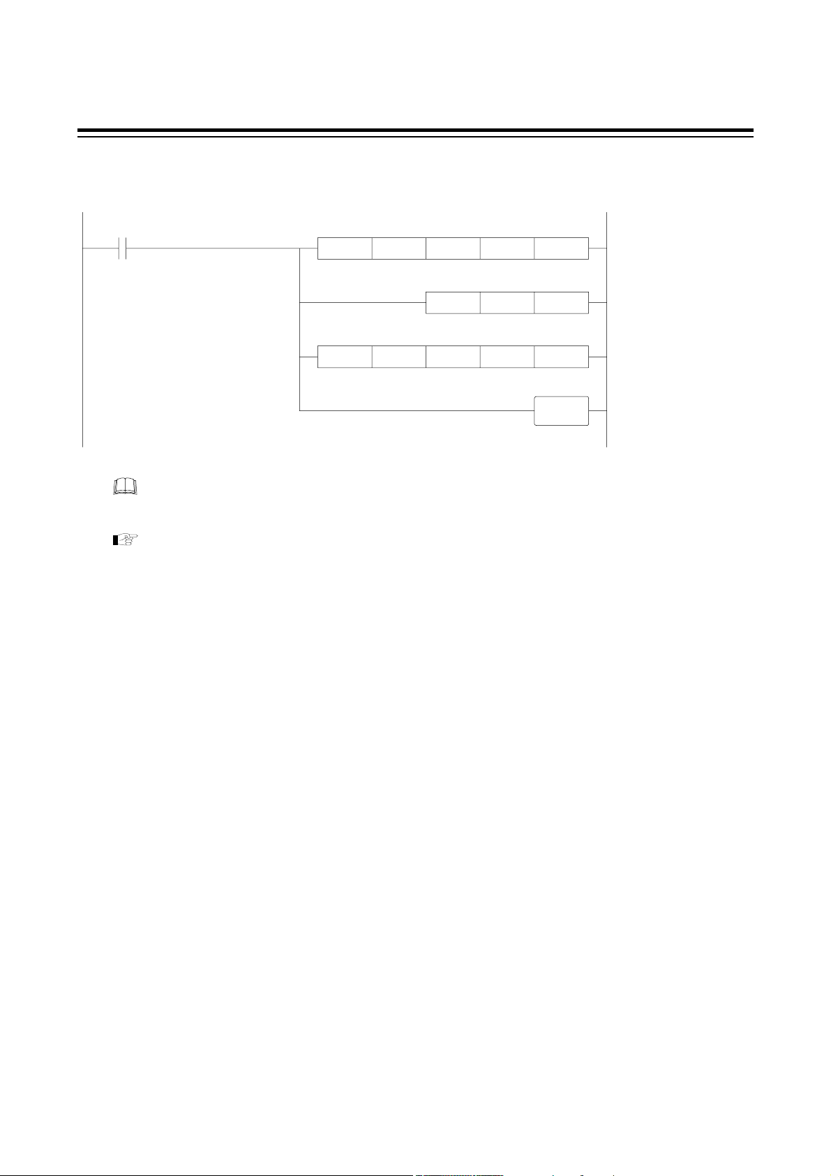
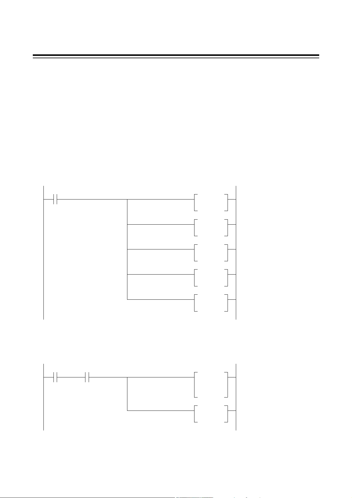
5.3 Example of Sequence Program
5.3.1 MELSEC Series (MITSUBISHI)
The ladder communication send/receive program using the MITSUBISHI MELSEC Series
(A2CCPU24) is described below.
Send data creation program (example)
M000
Send data
creation switch
Send program (example)
D11H0002MOVP
D12H0100MOVP
D13H0001MOVP
D14H0001MOVP
D15H0A0DMOVP
STX setting
Address setting = 01
Identifier setting
(Measured value)
Command (CMD) setting
Data setting
(Number of read data = 1)
Termination character
setting (CR, LF)
Send start
switch
X1E0
Send completion
46
Send
completion
Y1F0X1E0M001
Send
request
Data length settingD10K5MOVP
K6D10H0K61TOP
Y1F0SET
Y1F0RST
Transfer to send
buffer
Send request setting
Send request
resetting
IM9000F02-E3
Page 53
Receive program (example)
5. LADDER COMMUNICATION
X1E1
Receive data
read request
K1D20H80K61FROMP
ZD20MOVP
D21H81K61FROMP
K0Z
Y1F1
Acquisition of receive
character length
Stores character length
in index register
Transfers receive data
from receive buffer
Receive data read
completion setting
X1E0, X1E1, Y1F0, Y1F1 and K61 in the above program differ depending on the
programmable controller used to communication module address.
For details on setting the PLC, see the manual for "MITSUBISHI MELSEC Series."
IM9000F02-E3
47
Page 54
5. LADDER COMMUNICATION
5.3.2 C200HS (OMRON)
The communication send/receive program using the OMRON C200HS is described below.
The following types of OMRON C200HS with the built-in RS-232C post can perform non-protocol
communication.
• C200HS-CPU21
• C200HS-CPU23
• C200HS-CPU31
• C200HS-CPU33
Send data creation program (example)
30000
Send data
creation switch
Send program (example)
MOV
#0201
D1000
MOV
#0100
D1001
MOV
#0001
D1002
MOV
#0001
D1003
MOV
#0D0A
D1004
STX setting
Address setting = 01
Identifier setting
[Measured value (PV)]
Command setting
(CMD)
Data setting (DAT)
Number of read data = 1
Termination character
(CR, LF)
30001 26405
Send start
switch
48
Send ready
flag
TXD
D1000
#0000
#0010
RSET
30001
Send data head register
Control data
Number of send data bytes
Send start reset switch
IM9000F02-E3
Page 55

Receive program (example)
5. LADDER COMMUNICATION
26406
Receive completion
flag
For details on setting the PLC, see the manual for "OMRON C200HS."
RXD
D1100
#0000
#0256
Receive data head register
Control data
Number of stored data bytes
IM9000F02-E3
49
Page 56

6. TROUBLESHOOTING
The causes of and measures to be used for faulty controller status during communication are
described in the following. For trouble other than the below, contact us or your nearest RKC agent
after confirming Model No. and specifications.
RKC standard communication
Details Cause Measures
No response
EOT return
Trouble with and imperfect contact of
communication cable and connector
Device address designation differs Make reassignment after checking the device
Incorrect communication speed Set the communication speed suitable for the
Incorrect data configuration setting Make reassignment after checking the data
Transmission line is not set to the receive
state after data send
Incorrect identifier Make re-setting after checking the identifier
The identifier of a function not added to
the REX-F9000 is specified
BCC error Check BCC of the transmission data.
Check communication cables and connectors.
address by referring to "3.4 Device address
setting" (P. 9).
host computer by referring to
"3.5 Communication speed setting" (P. 11).
configuration by referring to "3.6 Data
configuration setting" (P. 13).
Check a program on the host computer side.
by referring to " Communication
identifier list" (P. 31).
NAK return
Data exceeds the setting range Check a data range.
The identifier of a function not added to
the REX-F9000 is specified
Make re-setting after checking the identifier
by referring to " Communication
identifier list" (P. 31).
50
IM9000F02-E3
Page 57

Ladder communication
Details Cause Measures
6. TROUBLESHOOTING
Trouble wit and imperfect contact
communication cable and connector
Device address designation differs Make reassignment after checking
Incorrect communication speed Set the communication speed suitable
No response Incorrect data configuration setting Make reassignment after checking
Transmission line is not set to the
receive state after data send
The specified identifier is not defined. Check the identifier.
The number of read data exceeds the
specified number.
Check communication cables and
connectors.
the device address by referring to
"3.4 Device address setting" (P. 9).
for the PLC by referring to
"3.5 Communication speed setting"
(P. 11).
the data configuration by referring to
"3.6 Data configuration setting" (P.
13).
Check the program on the PLC side.
Check the number of data.
No command length is correct
(Command length must be 10 bytes
including CR and LF.)
No settings are written Write data is out of the range Check a setting range.
An unsettable identifier (measured
value,
etc.) was specified.
All return characters
other than STX, device
address, identifier, CR
and LF are set to F.
Characters other than BCD codes (0 to
9) were used for communication data
(excluding STX, CR and LF)
Check the PLC side program.
Check whether they are identifiers
corresponding to settable items.
Make conversion to BCD coded
characters.
IM9000F02-E3
51
Page 58

7. ASCII 7-BIT CODE TABLE
b700001111
b600110011
b501010101
b5 to b7b4b3b2b1 01234567
00000NULDLE SP 0 @ P ‘ p
00011SOHDC1 ! 1 A Q a q
00102STXDC2 ” 2 B R b r
00113ETXDC3 # 3 C S c s
01004EOTDC4 $ 4 D T d t
01015ENQNAK % 5 E U e u
01106ACKSYM & 6 F V f v
01117BELETB ’ 7 G W g w
10008 BS CAN ( 8 H X h x
10019 HT EM ) 9 I Y i y
1010A LF SUB * : J Z j z
1011B VT ESC + ; K [ k {
1100C FF FS , < L ¥ l |
1101D CR GS - = M ] m }
1110E SO RS . > N ^ n ˜
1111F SI US / ? O _ o DEL
52
IM9000F02-E3
Page 59

The first edition: APR.1999
The third edition: AUG.2002 [IMQ01]
Page 60

RKC INSTRUMENT INC.
HEADQUARTERS: 16-6, KUGAHARA 5-CHOME, OHTA-KU TOKYO 146-8515 JAPAN
PHONE: 03-3751-9799 (+81 3 3751 9799)
E-mail: info@rkcinst.co.jp
FAX: 03-3751-8585 (+81 3 3751 8585)
IM9000F02-E3 AUG.2002
 Loading...