

Page 1

F
PF SERIES
RKC INSTRUMENT INC.
Ramp/Soak Controller
PF900
P
User’s Manual
This manual describes mounting, wiring and basic
operation only. Refer to the PF900/PF901 Instruction
Manual on the CD-ROM for Host communication,
control (Fixed set point control, Manual control
etc.), operation for function and Troubleshooting.
901
IMR02L04-E3
Page 2

NOTICE
This manual assumes that the reader has a fundamental knowledge of the principles of
electricity, process control, computer technology and communications.
The figures, diagrams and numeric values used in this manual are only for purpose of
illustration.
RKC is not responsible for any damage or injury that is caused as a result of using this
instrument, instrument failure or indirect damage.
RKC is not responsible for any damage and/or injury resulting from the use of instruments
made by imitating this instrument.
Periodic maintenance is required for safe and proper operation of this instrument. Some
components have a limited service life, or characteristics that change over time.
Every effort has been made to ensure accuracy of all information contained herein. RKC
makes no warranty expressed or implied, with respect to the accuracy of the information.
The information in this manual is subject to change without prior notice.
No portion of this document may be reprinted, modified, copied, transmitted, digitized,
stored, processed or retrieved through any mechanical, electronic, optical or other means
without prior written approval from RKC.
Windows is a trademark of Microsoft Corporation.
Modbus is a registered trademark of Schneider Electric.
Company names and product names used in this manual are the trademarks or registered trademarks
of the respective companies.
All Rights Reserved, Copyright 2010, RKC INSTRUMENT INC.
Page 3

Safety Precautions
Pictorial Symbols (safety symbols)
Various pictorial symbols are used in this manual to ensure safe use of the product, to
protect you and other people from harm, and to prevent damage to property. The symbols
are described below. Be sure you thoroughly understand the meaning of the symbols before
reading this manual.
: This mark indicates precautions that must
be taken if there is danger of electric shock,
fire, etc., which could result in loss of life or
injury.
This mark indicates that if these precautions
:
and operating procedures are not taken,
damage to the instrument may result.
: This mark indicates that all precautions
should be taken for safe usage.
An external protection device must be installed if failure of this instrument
could result in damage to the instrument, equipment or injury to personnel.
All wiring must be completed before power is turned on to prevent electric
shock, fire or damage to instrument and equipment.
This instrument must be used in accordance with the specifications to
prevent fire or damage to instrument and equipment.
This instrument is not intended for use in locations subject to flammable or
explosive gases.
Do not touch high-voltage connections such as power supply terminals, etc.
to avoid electric shock.
RKC is not responsible if this instrument is repaired, modified or
disassembled by other than factory-approved personnel. Malfunction can
occur and warranty is void under these conditions.
IMR02L04-E3
i-1
Page 4

This product is intended for use with industrial machines, test and measuring equipment.
(It is not designed for use with medical equipment and nuclear energy.)
This is a Class A instrument. In a domestic environment, this instrument may cause radio
interference, in which case the user may be required to take additional measures.
This instrument is protected from electric shock by reinforced insulation. Provide
reinforced insulation between the wire for the input signal and the wires for instrument
power supply, source of power and loads.
Be sure to provide an appropriate surge control circuit respectively for the following:
- If input/output or signal lines within the building are longer than 30 meters.
- If input/output or signal lines leave the building, regardless the length.
This instrument is designed for installation in an enclosed instrumentation panel. All
high-voltage connections such as power supply terminals must be enclosed in the
instrumentation panel to avoid electric shock by operating personnel.
All precautions described in this manual should be taken to avoid damage to the
instrument or equipment.
All wiring must be in accordance with local codes and regulations.
All wiring must be completed before power is turned on to prevent electric shock,
instrument failure, or incorrect action.
The power must be turned off before repairing work for input break and output failure
including replacement of sensor, contactor or SSR, and all wiring must be completed
before power is turned on again.
To prevent instrument damage or failure, protect the power line and the input/output lines
from high currents with a protection device such as fuse, circuit breaker, etc.
Prevent metal fragments or lead wire scraps from falling inside instrument case to avoid
electric shock, fire or malfunction.
Tighten each terminal screw to the specified torque found in the manual to avoid electric
shock, fire or malfunction.
For proper operation of this instrument, provide adequate ventilation for heat
dispensation.
Do not connect wires to unused terminals as this will interfere with proper operation of the
instrument.
Turn off the power supply before cleaning the instrument.
Do not use a volatile solvent such as paint thinner to clean the instrument. Deformation or
discoloration will occur. Use a soft, dry cloth to remove stains from the instrument.
To avoid damage to instrument display, do not rub with an abrasive material or push front
panel with a hard object.
Do not connect modular connectors to telephone line.
When high alarm with hold action is used for Event function, alarm does not turn on while
hold action is in operation. Take measures to prevent overheating which may occur if the
control device fails.
i-2
IMR02L04-E3
Page 5

Symbols
Pictorial Symbols (safety symbols)
: This mark indicates important information on installation,
handling and operating procedures.
: This mark indicates supplemental information on installation,
handling and operating procedures.
: This mark indicates where additional information may be located.
Character Symbols
This manual indicates 11-segment display characters as shown below.
0 1 2 3 4 5 6 7 8 9 Minus Period
0 1 2 3 4 5 6 7 8 9 - .
A B (b) C c D (d) E F G H I J K
A b C c D E F G H I J K
L M N (n) O (o) P Q q R r S T t
L M n o P Q q R r S T t
U u V W X Y Z Prime /
Temperature units
*
U u V W X Y Z ` / Š $ &
%
% ‹ _
8.
8
Dim lighting
Bright lighting
_
8.
Flashing
Abbreviation Symbols
The names of some items are indicated by alphabetical abbreviations in this manual.
Abbreviation
symbols
PV Measured value DI (1 to 6) Digital input (1 to 6)
SV Set value DO (1 to 12) Digital output (1 to 12)
AT Autotuning FBR Feedback resistance
ST Self-tuning
OUT (1 to 3) Output (1 to 3)
HBA (1 or 2) Heater break alarm (1 or 2)
CT (1 or 2) Current transformer (1 or 2)
LBA Control loop break alarm
LBD LBA deadband
Name
Abbreviation
symbols
Name
IMR02L04-E3
i-3
Page 6

Document Configuration
There are four manuals pertaining to this product. Please be sure to read all manuals specific
to your application requirements. If you do not have a necessary manual, please contact
RKC sales office, the agent, or download from the official RKC website.
The following manuals can be download from the official RKC website:
http://www.rkcinst.com/english/manual_load.htm.
Manual Manual Number Description Remarks
PF900/PF901
User’s Manual
PF900/PF901
Instruction Manual
PF900/PF901 Pattern
Record Sheet
Communication Setup
Tool for PF900/PF901
Program Controller
(WinUCI-PF900)
Instruction Manual
IMR02L04-E3
IMR02L03-E
IMR02L05-E
IMT01D09-E
This Manual.
This document describes installation,
wiring and basic operation.
This manual explains the method of
the mounting and wiring, the
operation of various functions, and
troubleshooting.
This spreadsheet is to record patterns
for Program control operation.
This document describes installation
of communication setup tool,
connection and setting of data.
Provided with
product
Provided with
product
On CD-ROM
[Downloadable]
i-4
IMR02L04-E3
Page 7

Contents
NOTICE
Safety Precautions ................................................................................................... i-1
Pictorial Symbols (safety symbols) ...................................................................................... i-1
WARNING .............................................................................................................................. i-1
CAUTION................................................................................................................................ i-2
Symbols .................................................................................................................... i-3
Pictorial Symbols (safety symbols) ...................................................................................... i-3
Character Symbols .............................................................................................................. i-3
Abbreviation Symbols ......................................................................................................... i-4
Document Configuration ........................................................................................... i-5
1. OUTLINE ............................................................................ 1-1
1.1 Handling Procedure to Operation ................................................................. 1-1
1.2 Checking the Product ................................................................................... 1-2
1.3 Model Code .................................................................................................. 1-3
Suffix code ................................................................................................................ 1-3
Quick start code 2 (Initial setting code) ..................................................................... 1-7
1.4 Parts Description ........................................................................................ 1-10
Front panel view ..................................................................................................... 1-10
Key operation ......................................................................................................... 1-13
Side view ................................................................................................................ 1-1 4
1.5 Input/Output and Function Blocks ............................................................... 1-15
Page
2. MOUNTING ........................................................................ 2-1
2.1 Mounting Environment .................................................................................. 2-1
2.2 Mounting Cautions ........................................................................................ 2-3
2.3 Dimensions ................................................................................................... 2-4
2.4 Procedures of Mounting and Removing ....................................................... 2-5
Mounting procedures ................................................................................................ 2-5
Removal procedures ................................................................................................ 2-6
3. WIRING .............................................................................. 3-1
3.1 Wiring Cautions ............................................................................................ 3-1
Power supply wiring .................................................................................................. 3-1
Input/Output wiring ................................................................................................... 3-2
Ground wiring ........................................................................................................... 3-3
Wiring method .......................................................................................................... 3-3
3.2 Terminal Layout ............................................................................................ 3-5
Terminal configuration .............................................................................................. 3-5
Isolations of the instrument ....................................................................................... 3-6
3.3 Wiring of Each Terminal ............................................................................... 3-7
Power supply ............................................................................................................ 3-7
Measured input (TC/RTD/Voltage/Current) [universal input] .................................... 3-8
IMR02L04-E3
i-5
Page 8

Output 1 (OUT1)/Output 2 (OUT2) ........................................................................... 3-9
Output 3 (OUT3) ..................................................................................................... 3-11
Digital input 1 to 11 (DI1 to DI6 [optional], DI7 to DI11 [standard]) ......................... 3-12
Digital output 1 to 4 (DO1 to DO4) [standard] ......................................................... 3-13
Digital output 5 to 12 (DO5 to DO12) [optional] ...................................................... 3-14
Current transformer (CT) input/Feedback resistance (FBR) input [optional] ........... 3-15
Communication 1/Communication 2 [optional] ....................................................... 3-16
4. BASIC OPERATION .......................................................... 4-1
4.1 Operation Menu ............................................................................................ 4-1
4.1.1 Mode switching ....................................................................................................... 4-1
4.1.2 Input type and input range display .......................................................................... 4-2
4.2 Changing Set Value ...................................................................................... 4-3
Numeric value setting ............................................................................................... 4-3
Setting item selection ............................................................................................... 4-5
4.3 Operation of the Direct Keys ......................................................................... 4-6
Direct key menu ....................................................................................................... 4-6
Direct key type .......................................................................................................... 4-7
4.4 Protecting Setting Data ................................................................................. 4-8
4.5 Parameter Description .................................................................................. 4-9
4.5.1 SV setting & monitor mode ..................................................................................... 4-9
SV setting mode ....................................................................................................... 4-9
Monitor mode ......................................................................................................... 4-12
4.5.2 Operation mode .................................................................................................... 4-14
Parameter list ......................................................................................................... 4-14
Parameter switching ............................................................................................... 4-15
4.5.3 Parameter setting mode ........................................................................................ 4-16
Setting type for Program pattern ............................................................................ 4-16
Parameter list [Partial setting type] ......................................................................... 4-17
Parameter switching [Partial setting type] ............................................................... 4-22
Parameter list [Batch setting type] .......................................................................... 4-26
Parameter switching [Batch setting type] ................................................................ 4-27
4.5.4 Setup setting mode ............................................................................................... 4-29
Parameter list ......................................................................................................... 4-29
Parameter switching ............................................................................................... 4-31
4.5.5 Engineering mode ................................................................................................. 4-32
Parameter list ......................................................................................................... 4-32
Parameter switching ............................................................................................... 4-44
Page
5. OPERATION ...................................................................... 5-1
5.1 Initial Setting ................................................................................................. 5-1
5.1.1 Check the parameter related to the input ................................................................ 5-1
5.1.2 Check the parameter related to the event action .................................................... 5-3
5.1.3 Check the parameter related to the control ............................................................. 5-4
5.1.4 Check set value of parameter for program control operation .................................. 5-6
5.2 Operating Precautions .................................................................................. 5-7
i-6 IMR02L04-E3
Page 9

Page
5.3 Type and Switching Procedures of Operation Mode .................................... 5-8
5.3.1 Type of Operation mode ......................................................................................... 5-8
5.3.2 Operation mode switching ....................................................................................... 5-8
5.4 Program Control Operation ......................................................................... 5-11
5.4.1 Program control mode display .............................................................................. 5-11
5.4.2 Program control operation procedures .................................................................. 5-12
5.4.3 Set up program patterns ...................................................................................... 5-12
5.4.4 Start/End Program control ..................................................................................... 5-20
5.4.5 Changing procedure of End segment number in Program pattern ........................ 5-22
5.5 Autotuning (AT) .......................................................................................... 5-23
5.6 Parameter Setting via Loader Communication ........................................... 5-27
5.6.1 Preparation ........................................................................................................... 5-27
5.6.2 Instructions for use ................................................................................................ 5-27
5.6.3 Connections for loader communication ................................................................. 5-28
5.6.4 Parameter setting .................................................................................................. 5-29
6. PROGRAM CONTROL ...................................................... 6-1
6.1 Memory Group .............................................................................................. 6-2
6.2 Program Control Start Selection ................................................................... 6-3
6.3 Search Function ........................................................................................... 6-7
6.4 Step (STEP) ................................................................................................. 6-8
6.5 Hold (HOLD) ................................................................................................. 6-9
6.6 Wait ............................................................................................................ 6-10
6.7 Repeat and Pattern Link ............................................................................. 6-14
6.8 Pattern End ................................................................................................. 6-17
6.9 Time Signal (Segment Signal) .................................................................... 6-21
6.10 Output Program ........................................................................................ 6-26
6.11 Edit Function ............................................................................................. 6-28
6.12 Tag Function ............................................................................................. 6-31
6.13 Forward/Back-up Function ........................................................................ 6-32
7. ERROR DISPLAY .............................................................. 7-1
7.1 Display when Input Error Occurs .................................................................. 7-1
7.2 Self-diagnostic Error ..................................................................................... 7-3
8. SPECIFICATIONS ............................................................. 8-1
IMR02L04-E3
i-7
Page 10

t
A
Contents (Categorized by purpose)
Confirm the state or model code of the instrument.
1.2
Checking the Product
1.3
Model Code
(P. 1-3)
(P. 1-2),
Mount or Wire the instrument
2. MOUNTING (P. 2-1), 3. WIRING (P. 3-1)
Refer to Basic Operations (such as Mode switching).
4.1 Operation Menu (P. 4-1)
4.2 Changing Set Value (P. 4-3)
4.3 Operation of the Direct Keys (P. 4-6)
4.4 Protecting Setting Data (P. 4-7)
PF900/PF901 Instruction Manual (on CD-ROM)
Refer to parameter type or switching procedure.
4.5 Parameter Description (P. 4-9)
PF900/PF901 Instruction Manual (on CD-ROM)
Refer to the Procedure before starting operation.
1.1 Handling Procedure to Operation (P. 1-1)
PF900/PF901 Instruction Manual (on CD-ROM)
Set operating condition before starting operation.
Parameters related to Input, Event action, Control
and Program control operation
5.1 Initial Setting (P. 5-1)
PF900/PF901 Instruction Manual (on CD-ROM)
Other Parameters (Engineering mode)
4.5.5 Engineering mode (P. 4-32)
PF900/PF901 Instruction Manual (on CD-ROM)
[Initial setting]
Refer to the procedure of Program control operation.
Set up Program pattern.
Start Program Control Operation.
Operate Program Control.
5.4.2 Program control operation procedures
(P. 5-12)
PF900/PF901 Instruction Manual (on CD-ROM)
PF900/PF901 Pattern Record Sheet (on CD-ROM)
5.4.3 Set up program patterns (P. 5-12)
4.5.3 Parameter setting mode (P. 4-16)
PF900/PF901 Instruction Manual (on CD-ROM)
5.4.4 Start/End Program control (P. 5-20)
PF900/PF901 Instruction Manual (on CD-ROM)
Switch Operation Mode.
Reset mode, Program control mode
4.3 Operation of the Direct Keys (P. 4-6)
5.4.4 Start/End Program control (P. 5-20)
Fixed set point control mode, Manual control mode
PF900/PF901 Instruction Manual (on CD-ROM)
Conduct Autotuning (AT).
5.5 Autotuning (AT) (P. 5-23)
PF900/PF901 Instruction Manual (on CD-ROM)
Refer to the error message.
7. ERROR DISPLAY (P. 7-1)
PF900/PF901 Instruction Manual (on CD-ROM)
Set Parameters by loader communication.
1.4 Parts Description (P. 1-10)
5.6 Parameter Setting via Loader
Communication (P. 5-27)
Communication Setup Tool for PF900/PF901
Program Controller (WinUCI-PF900) Instruction
Manual (on CD-ROM)
Set parameters related to Position proportioning
PID control.
1.3
Model Code
PF900/PF901 Instruction Manual (on CD-ROM)
Refer to each function.
Input
Measured input value (PV), Sampling cycle, PV uni
display, Power supply frequency, Input correction, Input
filter, Square root extraction, Feedback resistance (FBR)
input, Digital input (DI), Function and Settings for Input
error, Current transformer (CT) input, Setting limiter
Output
Output assignment (OUT1 to OUT3), Digital output (DO)
assignment (DO1 to DO12), Energized/De-energized
(OUT2, OUT3, DO1 to DO12), Output limiter, Proportional
cycle time (OUT1 to OUT3), Transmission output
Display
Graph display selection, Power saving mode
Event 1 to 4, Heater break a larm (HBA) and Control
loop break alarm (LBA)
Control
Control Action, Control response parameter, Position
proportioning PID control, Manual reset, Start action at
recovering power failure, Ramp/Soak stabilizer function,
utotuning (AT), Autotuning (AT) with learning, Level PID
Intercontroller Communication Function
Host Communication
PF900/PF901 Instruction Manual (on CD-ROM)
(P. 1-3)
IMR02L04-E3
i-8
Page 11

A
1. OUTLINE
1.1 Handling Procedure to Operation
Conduct necessary setting before operation according to the procedure described below.
Mounting and Wiring
Power ON
Switch mode from
RUN to RESET.
Set operation
conditions?
Yes (To change the operating condition)
Initial Setting
(Engineering mode)
Program pattern setting
Start test run.
Switch mode from
RESET to RUN.
Conduct Autotuning (AT)
Desired control result?
Yes
Start operation
Refer to 2. MOUNTING (P. 2-1) or 3. WIRING (P. 3-1).
Press the RESET key to go to the Reset mode (RESET) to stop the
operation. (RESET lamp turns on.)
No (No need to change the specification at ordering.)
Check the parameter related to the input (P. 5-1)
Check the parameter related to the event (P. 5-3)
Check the parameter related to the control action (P. 5-4)
For details of Engineering mode parameters, refer to
4.5.5 Engineering mode (P. 4-32).
Record data of Program pattern in the spreadsheet before setting.
(PF900/PF901 Pattern Record Sheet is included in the CD-ROM.)
Set Program pattern.
Refer to 5.4.3 Program pattern composition for setting example
of Program pattern (P. 5-12).
Press the RUN key to go to the Program control mode (RUN) to start
operation. (RUN lamp turns on.)
Refer to 5.4.4 Start/End Program control (P.5-20) for the
procedure to switch operation modes.
T lamp flashes
When the AT is finished, the controller will automatically returns to PID
control.
For details of Autotuning (AT), refer to 5.5 Autotuning (AT)
(P. 5-23).
For Autotuning (AT) with learning function, refer to
6. FUNCTION AND SETTING PROCEDURE of
the PF900/PF901 Instruction Manual (IMR02L03-E) on
the CD-ROM.
No
Conduct manual turning.
IMR02L04-E3 1-1
Page 12

1. OUTLINE
1.2 Checking the Product
Before using this product, check each of the following:
Model code
Check that there are no scratches or breakage in external appearance (case, front panel, or terminal, etc.)
Check that all of the items delivered are complete. (Refer to below)
Accessories
Details Q’TY Remarks
Instrument (PF900 or PF901)
Mounting brackets (with screw)
Seal (parts code: SAP-306)
Waterproof/Dustproof rubber
packing
(parts code: KFB900-36<1>)
PF900/PF901 User’s Manual
(IMR02L04-E)
CD-ROM 1
1
4
1
1
1
For waterproof/dustproof
Placed on the case
B6 size (hard copy)
Instruction manual included in CD-ROM:
ReadMe (text file)
Communication Setup Tool for PF900/PF901 Program
Controller (WinUCI-PF900) INSTRUCTION
MANUAL (IMT01D09-)*
PF900/PF901 Instruction Manual (IMR02L03-)*
PF900/PF901 Pattern Record Sheet*
* This manual can be downloaded from the official RKC website:
http://www.rkcinst.com/english/manual_load.htm.
Sold separately
Details Q’TY Remarks
Terminal cover
(parts code: KFB400-511(1))
Front cover
(parts code: KF9-352)
Current transformer
CTL-6-P-N [for 0 to 30 A] or
CTL-12-S56-10L-N [for 0 to 100 A]
If any of the products are missing, damaged, or if your manual is incomplete, please contact RKC
sales office or the agent.
2 Optional
1 Optional
Depending on the
order quantity
Optional
1-2
IMR02L04-E3
Page 13

1. OUTLINE
1.3 Model Code
Check that the product received is correctly specified by referring to the following model code list:
If the product is not identical to the specifications, please contact RKC sales office or the agent.
Suffix code
Specifications
Hardware coding only Quick start code1
PF900 (PV display: Green, SV display: Orange) (1) (2) (3) (4) (5) (6) (7) (8) (9) (10)
PF901 (PV and SV displays: White)
Relay contact
* /Y
M
Voltage pulse V
Output 1 (OUT1) 1
Voltage/Current [Refer to Output Code Table (P. 1-5)]
Triac T
Open collector D
None N
Relay contact M
Output 2 (OUT2) 1
Voltage pulse V
Voltage/Current [Refer to Output Code Table (P. 1-5)]
Triac T
Open collector D
N
Output 3 (OUT3) 1
None
Voltage pulse V
Voltage/Current [Refer to Output Code Table (P. 1-5)]
Open collector D
Power supply voltage
Digital output
2
(DO1 to DO12)
CT input or Feedback
resistance input
24 V AC/DC 3
100 to 240 V AC 4
4 points (DO1 to DO4) [Standard]
12 points (DO1 to DO12) C
None N
CT input (2 points)
Feedback resistance input 3
None
Communication 1 (RS-232C) and DI1 to DI6, No communication 2 1
Communication
function
Digital input
(DI1 to DI6)
4
Communication 1 (RS-422A) and DI1 to DI6, No communication 2 4
Communication 1 (RS-485) and DI1 to DI6, No communication 2 5
Communication 1 (RS-232C), Communication 2 (RS-485) 5 and DI1 to DI6 W
Communication 1 (RS-485), Communication 2 (RS-485)5 and DI1 to DI6 X
Communication 1 (None), Communication 2 (RS-485) 5and DI1 to DI6 Y
DI1 to DI6 D
6
Quick start code
No quick start code (Configured to factory set value)
Specify quick start code 1 1
Specify quick start code 1 and 2 (For Quick start code 2, refer to page 1-7) 2
Quick start code 1 is not specified
PID control with AT (Reverse action) F
PID control with AT (Direct action) D
Control Method
[Quick start code 1]
Heat/Cool PID control with AT (Cooling gain linear type) G
Heat/Cool PID control with AT (for Extruder [air cooling]) A
Heat/Cool PID control with AT (for Extruder [water cooling]) W
Position proportioning PID control without FBR (Reverse action) Z
Position proportioning PID control without FBR (Direct action) C
Measured input and
Range
[Quick start code 1]
Quick start code 1 is not specified
Refer to Range Code Table. (P.1-5, P. 1-6)
Instrument specification Version symbol
1
Some output types are not specifiable. Refer to the Output type availability on page 1-4.
2
The output type for DO1 to DO4 is Relay: for DO5 to DO12 is Open collector.
3
When Feedback resistance input is specified with other control method than Z or C, the factory set value is fixed to “Z: Position proportioning
PID control without FBR (Reverse action).”
4
Digital input 7 (DI7) to 11 (DI11) are standard.
5
Communication 2 is for the Intercontroller communication.
6
Set initial setting parameters in the Engineering mode. Refer to 4.5.5 Engineering mode (P.4-32) for description of the parameters.
Suffix code
4
T
F
N
N
No code
No code
Y
IMR02L04-E3
1-3
Page 14

1. OUTLINE
b
Output type availability
PID control with AT [: Usable : Not usable]
Details of output
Output type
Output 1
(OUT1)
Output 2
Output 3
a
MV1 and MV2 can be used as Transmission output.
b
Other: Transmission output of Measured value (PV), Deviation value (DEV), Set value (SV) monitor and Segment time (percentage)
(OUT2)
(OUT3)
Relay contact
Voltage pulse
Voltage/Current
Triac
Open collector
Relay contact
Voltage pulse
Voltage/Current
Triac
Open collector
Voltage pulse
Voltage/Current
Open collector
Manipulated output
value 1 (MV1)
Manipulated output
a
value 2 (MV2)
a
Heat/Cool PID control with AT [: Usable : Not usable]
Details of output
Output type
Relay contact
Output 1
(OUT1)
Output 2
(OUT2)
Output 3
(OUT3)
a
MV1 and MV2 can be used as Transmission output.
b
Other: Transmission output of Measured value (PV), Deviation value (DEV), Set value (SV) monitor and Segment time (percentage)
Voltage pulse
Voltage/Current
Triac
Open collector
Relay contact
Voltage pulse
Voltage/Current
Triac
Open collector
Voltage pulse
Voltage/Current
Open collector
Manipulated output
value 1 (MV1)
[heat-side]
Manipulated output
a
value 2 (MV2)
[cool-side]
a
Position proportioning PID control without FBR [: Usable : Not usable]
Details of output
Output type
Relay contact
Output 1
(OUT1)
Output 2
(OUT2)
Output 3
(OUT3)
a
MV1 and MV2 can be used as Transmission output.
b
Other: Transmission output of Measured value (PV), Deviation value (DEV), Set value (SV) monitor and Segment time (percentage)
c
When Position proportioning PID control is selected, it is still possible to assign PV, SV, SV monitor or Transmission output of Segment
time (percentage) to OUT 2 while Manipulated output value 2 (MV2) [close-side] cannot be used.
Voltage pulse
Voltage/Current
Triac
Open collector
Relay contact
Voltage pulse
Voltage/Current
Triac
Open collector
Voltage pulse
Voltage/Current
Open collector
Manipulated output
value 1 (MV1)
[open-side]
Manipulated output
a
value 2 (MV2)
[close-side]
a
Transmission output
Other
Transmission output
Other
Transmission output
Other
c
Output program
b
Output program
b
Output program
Event output
Event output
Event output
1-4
IMR02L04-E3
Page 15

Output Code Table
Output type Code Output type Code
Voltage (0 to 1 V DC) Available for OUT3 only 3 Voltage (1 to 5 V DC) 6
Voltage (0 to 5 V DC) 4 Current (0 to 20 mA DC) 7
Voltage (0 to 10 V DC) 5 Current (4 to 20 mA DC) 8
Range Code Table
Thermocouple (TC) input [voltage (low) group]
Type Code Measured range Code Measured range
K02 0 to 400 C KA4 0.0 to 800.0 F
K06 0 to 1200 C KB4 0.0 to 2400.0 F
K09 0.0 to 400.0 C KC5 328 to 2502 F
K
J
T
E
L
U
N
R
S
B
W5Re/W26Re
PLII
PR40-20
K23 0.0 to 1300.0 C KC9 328.0 to 2502.0 F
K35 200.0 to 400.0 C
K41 200 to +1372 C
K42 200.0 to 1372.0 C
J15 200 to
J16 0.0 to 1200.0 C JB6 0.0 to 800.0 F
J27 200.0 to 400.0 C JB9 328 to 2192 F
J29 200.0 to 1200.0 C JC9 328.0 to 2192.0F
T06 0.0 to 400.0 C TA7 0.0 to 700.0 F
T13 200.0 to 200.0 C TB7 300.0 to 700.0 F
T16 200 to 400 C TC2 328.0 to 752.0 F
T19 200.0 to 400.0 C TC9 328 to 752 F
E06 200 to 1000 C EA6 0.0 to 1800.0 F
E08 0.0 to 1000.0 C EB1 328 to 1832 F
E17 200.0 to 200.0 C EB3 328.0 to 1832.0 F
E20 200.0 to 1000.0 C
L04 0.0 to 900.0 C LA3 0 to 1652 F
L05 0 to 900 C LA6 0.0 to 1600.0 F
LB1 0.0 to 1652.0 F
U04 0.0 to 600.0 C UB1 0.0 to 1100.0 F
U08 0 to 600 C UB3 0.0 to 1112.0 F
UB4 0 to 1112 F
N02 0 to 1300 C NA4 0.0 to 2300.0 F
N05 0.0 to 1300.0 C NA7 0 to 2372 F
NA8 0.0 to 2372.0 F
R05 0.0 to 1700.0 C RA5 0.0 to 3200.0 F
R07 50 to 1768 C RA7 58 to 3214 F
R08 50.0 to 1768.0C RA8 58.0 to 3214 .0 F
S04 0.0 to 1700.0 C SA5 0.0 to 3200.0 F
S06 50 to 1768 C SA7 58 to 3214 F
S07 50.0 to 1768.0 C SA8 58.0 to 3214.0 F
B03 0 to 1800 C BA9 0.0 to 3200.0 F
B04 0.0 to 1800.0 C BB2 0 to 3272 F
BB3 0.0 to 3272.0 F
W03 0 to 2300 C WA2 0 to 4200 F
W04 0.0 to 2300.0 C WA6 0.0 to 2200.0 F
W06 0.0 to 1200.0 C WA8 0.0 to 4200.0 F
A02 0 to 1390 C AA2 0 to 2534 F
A05 0.0 to 1300.0 C AA5 0.0 to 2300.0 F
A06 0.0 to 1390.0 C AA7 0.0 to 2534.0 F
F01 0.0 to 1800.0 C FA1 0.0 to 3200.0 F
F02 0 to 1800 C FA2 0 to 3200 F
1200 C JB5 0.0 to 2100.0 F
1. OUTLINE
IMR02L04-E3
1-5
Page 16

1. OUTLINE
Resistance temperature detector (RTD) input [voltage (low) group]
Type Code Measured range Code Measured range
D21 200.0 to 200.0 C DB8 300.0 to 1200.0 F
D25 200.0 to 600.0 C DC9 328.0 to 1562.0 F
Pt100
JPt100
D34 100.00 to 150.00 C DD2 328 to 1562 F
D35 200.0 to 850.0 C
D36 200 to 850 C
P10 0.0 to 500.0 C
P21 200.0 to 200.0 C
P26 200.0 to 600.0 C
P29 100.00 to 150.00 C
P30 200.0 to 640.0 C
P31 200 to 640 C
Voltage input, Current input
Type Code Voltag e input group Measured range
Voltage 0 to 10 mV DC 101
Voltage 0 to 100 mV DC 201
Voltage 0 to 1 V DC 301
Voltage 0 to 5 V DC 401
Voltage 1 to 5 V DC 601
Current 0 to 20 mA DC 701
Current 4 to 20 mA DC 801
Voltage 100 to 100 mV DC 901
Voltage 10 to 10 mV DC 903
Voltage 10 to 10 V DC 904
Voltage 5 to 5 V DC 905
Voltage (low) input group
Voltage (high) input group Voltage 0 to 10 V DC 501
Current input group
Voltage (low) input group Voltage 1 to 1 V DC 902
Voltage (high) input group
Programmable range
Setting range: 19999 to 32000
[The decimal point position is selectable]
(Factory set value: 0.0 to 100.0)
1-6
IMR02L04-E3
Page 17

1. OUTLINE
Quick start code 2 (Initial setting code)
Quick start code 2 tells the factory to ship with each parameter preset to the values detailed as specified by
the customer. Quick start code is not necessarily specified when ordering, unless the preset is requested.
These parameters are software selectable items and can be re-programmed in the field via the manual.
Quick start code 2 (Initial setting code)
Specifications
DI assignment DI1 to DI6 [Refer to DI Assignment Code Table (P. 1-7)]
Digital output 1 Event 1 [Deviation high] N
(DO1) Assign other DO type [Refer to DO Type Code Table (P. 1-8)]
Digital output 2 Event 2 [Deviation low] N
(DO2) Assign other DO type [Refer to DO Type Code Table (P. 1-8)]
Digital output 3 Time signal 1 N
(DO3) Assign other DO type [Refer to DO Type Code Table (P. 1-9)]
Digital output 4 Pattern end signal N
(DO4) Assign other DO type [Refer to DO Type Code Table (P. 1-9)]
No CT1 and CT2 N
CT1: CTL-6-P-N CT2: No use P
CT type CT1: CTL-12-S56-10L-N CT2: No use S
CT1: CTL-6-P-N CT2: CTL-6-P-N T
CT1: CTL-12-S56-10L-N CT2: CTL-12-S56-10L-N U
Communication 1
protocol
None
RKC communication (ANSI X3.28-1976) 1
Modbus 2
Factory set value of DO5 through DO12 (optional) is Time signal.
DI Assignment Code Table
(DI1 to DI6: Optional DI7 to DI11: Standard function)
DI number
Digital input 1 (DI1) PTN1 PTN1 WAIT release WAIT release WAIT release WAIT release
Digital input 2 (DI2) PTN2 PTN2 WAIT release WAIT release WAIT release WAIT release
Digital input 3 (DI3) PTN4 PTN4 WAIT release WAIT release WAIT release WAIT release
Digital input 4 (DI4) PTN8 PTN8 WAIT release WAIT release WAIT release WAIT release
Digital input 5 (DI5) PTN16 PTN16 WAIT release WAIT release WAIT release WAIT release
Digital input 6 (DI6) P. SET P. SET WAIT release WAIT release WAIT release WAIT release
Digital input 7 (DI7) RESET RESET PTN1 PTN1 RESET RESET
Digital input 8 (DI8) RUN RUN PTN2 PTN2 RUN RUN
Digital input 9 (DI9) STEP STEP PTN4 PTN4 STEP STEP
Digital input 10 (DI10) HOLD PTN32 PTN8 PTN8 HOLD HOLD
Digital input 11 (DI11) PTN32 PTN64 P. SET PTN16 Direct/Reverse PTN_INC
PTN1, 2, 4, 8, 16, 32, 64: Pattern number switch STEP: Step (STEP) function
P. SET: Pattern set HOLD: Hold (HOLD) function
WAIT release: Wait state release Direct/Reverse: Direct/Reverse action switching
RESET: Res e t m o d e (RESET) setting PTN_INC: Pattern increment
RUN: Program control mode (RUN) setting
0 1 2 3 4 5
Code (0 to 5)
(1) (2) (3) (4) (5) (6) (7)
N
IMR02L04-E3
1-7
Page 18

1. OUTLINE
DO Type Code Table
Digital output 1 (DO1)
Code Type Code Type Code Type
N None L Event 1 process low
with hold action
A Event 1 deviation high P Heater break alarm 1 (HBA1) 2 Event 1 manipulated output value
B Event 1 deviation low Q Heater break alarm 2 (HBA2) 3 Event 1 manipulated output value
C Event 1 deviation high/low R Control loop break alarm (LBA) 4 Event 1 manipulated output value
D Event 1 band S FAIL (de-energized fixed) 5 Time signal 1
1 Event 1 manipulated output value
(MV1) high [heat-side]
(MV1) low [heat-side]
(MV2) high [cool-side]
(MV2) low [cool-side]
E Event 1 deviation high
with hold action
F Event 1 deviation low
with hold action
G Event 1 deviation high/low
with hold action
H Event 1 process high W Event 1 set value (SV) low 9 Pattern end signal
J Event 1 process low X Event 1 deviation high/low
K Event 1 process high
with hold action
T Feedback resistance (FBR) input
error
U Event 1 band
(High/Low individual setting)
V Event 1 set value (SV) high 8 Time signal 4
(High/Low individual setting)
Y Event 1 deviation high/low
with hold action
(High/Low individual setting)
6 Time signal 2
7 Time signal 3
Digital output 2 (DO2)
Code Type Code Type Code Type
N None L Event 2 process low
with hold action
A Event 2 deviation high P Heater break alarm 1 (HBA1) 2 Event 2 manipulated output value
B Event 2 deviation low Q Heater break alarm 2 (HBA2) 3 Event 2 manipulated output value
C Event 2 deviation high/low R Control loop break alarm (LBA) 4 Event 2 manipulated output value
D Event 2 band
E Event 2 deviation high
with hold action
F Event 2 deviation low
with hold action
G Event 2 deviation high/low
with hold action
H Event 2 process high W Event 2 set value (SV) low 9 Pattern end signal
S FAIL (de-energized fixed) 5 Time signal 1
T Feedback resistance (FBR) input
error
U Event 2 band
(High/Low individual setting)
V Event 2 set value (SV) high 8 Time signal 4
1 Event 2 manipulated output value
(MV1) high [heat-side]
(MV1) low [heat-side]
(MV2) high [cool-side]
(MV2) low [cool-side]
6 Time signal 2
7 Time signal 3
J Event 2 process low X Event 2 deviation high/low
(High/Low individual setting)
K Event 2 process high
with hold action
Y Event 2 deviation high/low
with hold action
(High/Low individual setting)
1-8
IMR02L04-E3
Page 19

Digital output 3 (DO3)
Code Type Code Type Code Type
N None L Event 3 process low
with hold action
A Event 3 deviation high P Heater break alarm 1 (HBA1) 2 Event 3 manipulated output value
B Event 3 deviation low Q Heater break alarm 2 (HBA2) 3 Event 3 manipulated output value
C Event 3 deviation high/low R Control loop break alarm (LBA) 4 Event 3 manipulated output value
D Event 3 band S FAIL (de-energized fixed) 5 Time signal 1
1 Event 3 manipulated output value
(MV1) high [heat-side]
(MV1) low [heat-side]
(MV2) high [cool-side]
(MV2) low [cool-side]
1. OUTLINE
E Event 3 deviation high
with hold action
F Event 3 deviation low
with hold action
G Event 3 deviation high/low
with hold action
H Event 3 process high W Event 3 set value (SV) low 9 Pattern end signal
J Event 3 process low X Event 3 deviation high/low
K Event 3 process high
with hold action
T Feedback resistance (FBR) input
error
U Event 3 band
(High/Low individual setting)
V Event 3 set value (SV) high 8 Time signal 4
(High/Low individual setting)
Y Event 3 deviation high/low
with hold action
(High/Low individual setting)
6 Time signal 2
7 Time signal 3
Digital output 4 (DO4)
Code Type Code Type Code Type
N None L Event 4 process low
with hold action
A Event 4 deviation high P Heater break alarm 1 (HBA1) 2 Event 4 manipulated output value
B Event 4 deviation low Q Heater break alarm 2 (HBA2) 3 Event 4 manipulated output value
C Event 4 deviation high/low R Control loop break alarm (LBA) 4 Event 4 manipulated output value
D Event 4 band S FAIL (de-energized fixed) 5 Time signal 1
1 Event 4 manipulated output value
(MV1) high [heat-side]
(MV1) low [heat-side]
(MV2) high [cool-side]
(MV2) low [cool-side]
E Event 4 deviation high
with hold action
F Event 4 deviation low
with hold action
G Event 4 deviation high/low
with hold action
H Event 4 process high W Event 4 set value (SV) low 9 Pattern end signal
J Event 4 process low X Event 4 deviation high/low
K Event 4 process high
with hold action
T Feedback resistance (FBR) input
error
U Event 4 band
(High/Low individual setting)
V Event 4 set value (SV) high 8 Time signal 4
(High/Low individual setting)
Y Event 4 deviation high/low
with hold action
(High/Low individual setting)
6 Time signal 2
7 Time signal 3
IMR02L04-E3
1-9
Page 20

1. OUTLINE
A
y
y
y
y
‰
A
1.4 Parts Description
Front panel view
Time unit displa
TIME displa
T lamp
TS lamp
Gradient state lamp
PTN displa
SEG displa
State display lamp
PV
††††‡
TM
H:M:S SV
‡
DO
1
TS
T
PTN
88
SEG
88
RESET RUN FIX MAN HOLD
MONI
PF900
2 3 4 5 6 7 8 9 10 11 12ALM
OUT1
OUT2
OUT3
SET
MODE
STEP R.SET
!
PTN END
PV display
PV unit display
SV display
Set lock display
ALM lamp
DO lamp/DO number lamp
Dot display
Output lamp
PV display [PF900: Green/P F901: White]
Displays Measured value (PV) or various parameter symbols.
PV unit display [PF900: Green/PF901: White]
Displays C, F or . Displays % only for parameters on a percentage basis.
SV display [PF900: Orange/ PF901: White]
Displays segment level, Set value (SV), Manipulated output value (MV) or various parameter set
values.
Set lock display [PF900: Orange/PF901: White]
Displays key character “!” when the key operation is prohibited.
ALM lamp [Red]
Lights when Event occurs (Event 1 through 4, HBA1, HBA2, LBA, Self-diagnostic error,
communication error or FAIL). Event type may be checked by Event state monitor (except
Self-diagnostic error, communication error and FAIL).
DO lamp/DO number lamp [PF900: Green/PF901: White]
DO: Lights alphabet of the DO lamp at all times (when the power is on).
DO number ( 1 to 12 ):
Lights when the output corresponding to each lamp is ON.
Dot display [White] (20 dots for horizontal axis, 10 dots for vertical axis)
The bar graph displays the progress of program pattern, or increase and decrease of Manipulated
output value (MV). Segments in process flash in the Program control mode.
It is possible to change the color of dots into red for Event or Self-diagnostic error.
1-10
IMR02L04-E3
Page 21

Output lamp [PF900: Green/PF901: White]
OUT1: Lights when output 1 is turned on.*
OUT2: Lights when output 2 is turned on.*
OUT3: Lights when output 3 is turned on.*
*
For voltage output or current output, the output lamp flashes when the output value goes below 0 %
and lights when the value goes above 0 %.
State display lamp [Green or Orange]
The control mode in progress and the operation function lamps will be lit.
Character Lamp color Details
RESET
RUN
FIX
MAN
HOLD
Green or
Orange
Green or
Orange
Green or
Orange
Green or
Orange
Green
STEP R.SET Green
STEP R.SET Green
PTN END Green
PTN END Green
Reset mode (RESET) light will be orange.
When other modes are selected the light will be green.
Program control mode (RUN) light will be orange.
When other modes are selected the light will be green.
Fixed set point control mode (FIX) light will be orange.
When other modes are selected the light will be green.
Manual control mode (MAN) will be orange.
When other modes are selected the light will be green.
Light is green when HOLD key is operative.
Light is green when STEP R.SET key is operative.
Light is green when STEP R.SET key is operative.
Light is green when PTN END key is operative.
Light is green when PTN END key is operative.
Flashing of State display lamp
When Direct key type is “Press twice,” State display lamp flashes when the Direct key is
pressed once (except the PTN END key).
Gradient state lamp [PF900: Green/PF901: White]
Lights the lamp of the gradient in process.
Rise Soak Drop
In the Program control mode (RUN):
Lights the lamp of the gradient of the segment in process.
Fixed set point control mode (FIX):
Lights soak lamp
In the Manual control mode (MAN) or the Reset mode (RESET):
Gradient state lamp does not light.
1. OUTLINE
IMR02L04-E3
1-11
Page 22

1. OUTLINE
SEG display [PF900: Green/PF901: White]
Displays segment number (from 1 to 99).
In the Reset mode (RESET):
Displays the segment number before running the operation.
In the Program control mode (RUN):
Displays the segment number in process.
In the Fixed set point control mode (FIX) or the Manual control mode (MAN):
Displays the segment being displays in the previous mode.
PTN display [PF900: Green/PF901: White]
Displays program pattern number (from 1 to 99).
In the Reset mode (RESET):
Displays the Program pattern number being set.
In the Program control mode (RUN):
Displays the program pattern number in process.
In the Fixed set point control mode (FIX) or the Manual control mode (MAN):
Displays Program pattern number in the previous mode.
TS lamp [PF900: Green/PF901: White]
Lights when Time signal output is turned on.
AT lamp [PF900: Green/PF901: White]
Flashes during the Autotuning (including Autotuning with learning function).
(AT end: AT lamp turns off)
TIME display [PF900: Orange/PF901: White]
Displays segment time or character of parameter.
Time unit display [PF900: Green/PF 90 1: White]
Displays time unit of Segment time. [hour (H): minute (M) or minute (M): second (S)]
1-12
IMR02L04-E3
Page 23

‰
A
Key operation
Loader communication
connector
Direct keys
It is possible to easily change the operation mode or switch the state of operation in process by using
the direct keys. Use the RESET key, RUN key, FIX key or MAN key to change the operation mode.
Use the HOLD key, STEP key, R.SET key, PTN key or END key to switch the state of operation.
PV
TM
††††‡
H:M:S
SV
‡
DO
1
TS
T
PTN
88
SEG
88
RESET RUN FIX MAN HOLD
MONI
PF900
2 3 4 5 6 7 8 9 10 11 12ALM
OUT1
OUT2
OUT3
SET
MODE
1. OUTLINE
!
STEP R.SETPTN END
Direct keys
Up key
Down key Shift key Set (SET) keyMonitor key
Key name
RESET key
RUN key
FIX key
MAN key
HOLD key
Lamp to
be lit
RESET
RUN
FIX
MAN
HOLD
Press the RESET key to go to the Reset mode (RESET).
Press the RUN key to go to the Program control mode (RUN).
Press the FIX key to go to the Fixed set point control mode (FIX).
Press the MAN key to go to the Manual control mode (MAN).
Press the HOLD key to suspend the operation in process.
Press again to release the Hold mode. [Hold (HOLD) function]
Details
It is possible to skip one segment of the program pattern in
STEP R.SET
STEP R.SET key
STEP R.SET
PTN END
PTN END key
progress by pressing the STEP R.SET key.
[Step (STEP) function]
Press the
key once to go back to the previous parameter
when passing the parameter setting item to be changed.
Switch display to the setting display of the Execution pattern
number [PTN].
PTN END Switch display to the Program end screen [P.END].
IMR02L04-E3
1-13
Page 24

1. OUTLINE
Up key
Increase numerals. *
Press the Up key to set segment time in the Program control mode (RUN).
To scroll through numbers faster, press and hold the Up key. *
Down key
Decrease numerals. *
Press the DOWN key to turn back to the previous value when passing the seg ment time to be set in
the Program control mode. To scroll back through numbers faster, press and hold the DOWN key. *
Shift key
Shift digits when settings are changed.
Used to selection operation between modes.
Set (SET) key
Used for parameter calling up and set value registration.
Monitor key
Use to switch the monitor screen.
Pressing the
to the PV/SV monitor screen.
key while any screen other than the Monitor mode screen is being displayed returns
Loader communication connector
Designed to connect with W-BV-03 cable for loader communication (RKC product)
Continuously pressing the and the keys will accelerate number change.
*
The following acceleration settings may be changed by using communication:
Key accelerating speed setting [Communication identifier KV] **
Key acceleration speed Forward/Back-up [Communication identifier KW] **
** Refer to the PF900/PF901 Instruction Manual (IMR02L03-E) on the CD-ROM.
Side view
Input select switch
Input select switch
Use to switch Input groups of Measurement input. Set Voltage (low) input group, Voltage (high) input
group or Current input group. (Refer to P. 3-8)
1-14
IMR02L04-E3
Page 25

Current
1.5 Input/Output and Function Blocks
This section describes the input/output and function blocks of the instrument.
Up to 99 patterns and 1024 segments
(Max. 99 segments for each pattern)
Segment level
Segment time
PID memory group
Event memory group
Wait memory group
Time signal
Output program memory group
Pattern link/Repeat
Segment repeat
Copy function
Tag function
Data clear (Parameter initialization)
Measured input
Voltage/
Current transformer (CT) input
CT1 *
CT2 *
Feedback resistance (FBR) input
FBR *
Digital input 1 to 11
Dry contact
DI1 to 6 *
DI7 to 11
RS-485/RS-422A/
RS-232C
communication*
RS-485
Intercontroller
communication*
communication*
Program setting
Set value (SV) for Fixed set
point control mode (FIX)
Operation mode transfer
Input processing
TC
RTD
(CT input is not specifiable with FBR.)
(FBR is not specifiable with CT input.)
Host
Loader
(front)
PV digital filter
PV bias
PV ratio
Square root extraction
(Voltage/Current
input)
Current capture
processing
Input processing
DI function assignment
Reset mode setting
Program control mode
setting
Hold function
Step function
Direct action/Reverse
action
Wait state release
Pattern number switch
Pattern increment
Protocol selections
communication
Modbus
For master/slave link operation
RKC communication
COM-K must be used to
connect to a PC via the
loader port.
RKC
Modbus
Reset mode
RUN
FIX
RESET
MAN
Manual
manipulated
output setting
Program control
PV start
Time signal output (8 points)
Hold function
Step function
Wait function
Pattern end function
Output program function
Forward/Back-up function
Control mode
PID control
Heat/Cool PID control
ON/OFF action
Position proportioning PID
control
Direct/Reverse action
Manual control
Fixed set point control
Autotuning (AT)
Auto tuning (AT) with
learning function
Level PID (8 levels)
Segment PID
Ramp/Soak stabilizer
function
Event, Alarm
Event 1 to 4
(Hold action, Event timer or
interlock)
Heater break alarm (HBA) 1,2
(Number of delay times)
Control loop break alarm (LBA)
(Contact open when error
FAIL
occurs)
Energized/De-energized
Selectable for OUT2, OUT3
and DO1 through DO12
(OUT1 is fixed to Energized)
Communication
Host communication
Intercontroller communication
Loader communication
Power supply
100 to 240 V AC, 24 V AC or 24 V DC
Open side for Position
proportioning control
Close side for Position
proportioning control
Transmission output
(Voltage/Current)*
Measured value (PV)
Set value (SV)
Deviation value (DEV)
Segment time
(percentage)
(Output scaling is fixed)
DO function assignment
Time signal 1 to 8
Event 1 to 4
HBA1, HBA2
LBA
Input error state
RUN mode state
FIX mode state
MAN mode state
Ramp state
Soak state
Hold state
Wait state
Pattern end signal
Autotuning (AT) state
FAIL state
Host communication
error
Intercontroller
communication error
FBR input error
Measured value (PV) monitor
Segment level/Segment time
Program pattern number/Segment number
Pattern/Segment remaining time monitor
Current transformer (CT) input value monitor
Manipulated output value (MV) monitor
Pattern display (dot display)
Operation lamps
Operation key: MONI, SET, MODE and
, keys
Direct key: RESET, RUN, FIX, MAN,
HOLD, STEP R.SET and
PTN END keys
Control output
(heat-side)
Control output
(cool-side)
Output program
Output scaling
Display
Key operation
Control output
Relay contact
Voltage pulse
Voltage/Current
Triac
Open collector
Output selections
Digital output 1 to 4
Relay contact
Digital output 5 to 12
Open collector
Marked*: Optional
1. OUTLINE
OUT1
OUT2
Voltage pulse
Voltage/Current
Open collector
OUT3 *
DO1 to 4
DO5 to 12 *
IMR02L04-E3
1-15
Page 26

MEMO
1-16 IMR02L04-E3
Page 27

2. MOUNTING
To prevent electric shock or instrument failure, always turn off the power before
mounting or removing the instrument.
2.1 Mounting Environment
(1) The PF900/901 is intended to be used under the following environmental conditions.
IEC61010-1 OVERVOLTAGE CATEGORY II, POLLUTION DEGREE 2
Indoor use, Altitude up to 2000 m
(2) Use this instrument within the following allowable range:
Allowable ambient temperature: 10 to 55 C
Allowable ambient humidity: 5 to 95 %RH
(Absolute humidity: MAX.W.C 29 g/m
(3) Do not use this instrument in the following environment:
Sudden change in ambient temperature
Condensation or icing
Corrosive or inflammable gases.
Strong vibration or impact
Water, oil, chemicals, vapor or steam splashes.
Excessive dust, salt or iron particles.
Excessive induction noise, static electricity, magnetic fields or noise.
Direct air flow from an air conditioner.
Exposure to direct sunlight.
Direct radiant heat
(4) If this instrument is permanently connected to equipment, it is important to include a switch or
circuit-breaker into the installation. This should be in close proximity to the equipment and within easy
reach of the operator. It should be marked as the disconnecting device for the equipment.
3
dry air at 101.3 kPa)
IMR02L04-E3 2-1
Page 28

2. MOUNTING
2.2 Mounting Cautions
To avoid problems, consider the following cautions when
mounting the PF900/901:
Allow space for draft to release heat.
Make sure to cool down the ambient temperature by using
forced-air cooling system when the ambient temperature
exceeds 55 C. Do not expose this instrument directly to
cool air from the forced-air cooling system.
Do not mount this instrument directly above equipment
Fresh air inlet
that generates large amount of heat (heaters, transformers,
semi-conductor functional devices, large-wattage
resistors.)
To improve noise immunity or safety, consider the
following cautions:
High voltage equipment: Do not mount within the
same panel.
Power lines: Separate at least 200 mm.
Rotating machinery: Separate as far as possible.
Wiring duct for
communication line
Wiring duct for
input signal
Wiring duct for
output signal
100 mm
or more
RS-232C,
RS-422A,
RS-485,
etc.
Fuse, timer, relay etc.
(Do not mount power
Instrument
device, heating
equipment etc.)
Mount PF900/901 within the range of installation position (90).
Concern the viewing angle of the display when mounting PF900/901.
Viewing angle: Horizontal 90/vertical 90 (contrast ratio 20:1)
Example of cooling panel
Cooling fun
Instrument
Filter
Distance from rotating machinery lines
Rotating machinery lines
200 mm
or more
200 mm
or more
Instrument
Wiring duct for power line
(such as motor and heater)
200 mm or more
Circuit breaker,
fuse, etc.
Power device,
transformer,
relay, etc.
Power device
2-2
IMR02L04-E3
Page 29

Take caution to avoid being hurt by the sharp-pointed tip of the screw installed in the mounting
bracket.
Tip of screw installed in mounting bracket
Install two mounting brackets each on top and the bottom of the instrument. Do not install them in the
grooves located on the side surfaces.
Mounting
bracket
Mounting
bracket
Mounting
bracket
Correct installation Incorrect installation
2. MOUNTING
Mounting
bracket
IMR02L04-E3
2-3
Page 30

2. MOUNTING
2.3 Dimensions
Dimensions
96
96
11
(Unit: mm)
91.8
*2
91.8
106.1
*1
1
80
90.1
[Panel thickness: 1 to 10 mm]
*1 Waterproof/dustproof rubber packing (Model code: KFB900-36 <1>)
*2 Terminal cover [sold separately] (Model code: KFB 400-511(1))
Panel cutout
To keep the instrument as waterproof as possible, make sure that the panel surface has no burr or
distortion where the hole is to be cut out.
92
0.8
0
(Unit: mm)
0
0.8
92
30
25
2-4
IMR02L04-E3
Page 31

2. MOUNTING
2.4 Procedures of Mounting and Removing
Mounting procedures
The front of the controller conforms to IP55 (NEMA Type 3) when mounted to the panel. For effective
Waterproof/Dustproof, the waterproof/dustproof rubber packing must be securely placed between instrument
and panel without any gap. If waterproof/dustproof rubber packing is damaged, please contact RKC sales
office or the agent.
1. Prepare the panel cutout as specified in 2.3 Dimensions.
(Panel thickness: 1 to 10 mm)
2. Set the water/dustproof rubber packing on the case
from the back side of the instrument shown in Fig. 2.2.
Insert the instrument through the panel cutout.
To replace Waterproof/dustproof rubber
packing, refer to APPENDIX of
the PF900/PF901 Instruction Manual
(IMR02L03-E) on the CD-ROM.
3. Insert the mounting bracket into the mounting groove
of the instrument. (Fig. 2.3)
4. Push the mounting bracket forward until the bracket is
firmly secured to the panel. (Fig. 2.4)
5. Turn only one full revolution after the screw touches
the panel. (Fig. 2.5)
If the screw has been rotated too tight, the screw
may turn idle. In such a case, loosen the screw
once and tighten it again until the instrument is
firmly fixed.
6. The other mounting bracket should be installed the
same way described in 3 to 5.
Fig. 2.1
Mounting
holes
Fig. 2.2
Fig. 2.3
Fig. 2.4
Fig. 2.5
Panel
Panel
IMR02L04-E3
2-5
Page 32

2. MOUNTING
Removal procedures
1. Turn the power OFF.
2. Remove the wiring.
3. Loosen the screw of the mounting bracket.
4. Remove the mounting bracket by pulling up
(Fig. 2.7 [A]) and forward (Fig. 2.7 [B]) while
holding the rear (Fig. 2.6).
5. The other mounting bracket should be removed in
the same way as described in
3 and 4.
6. Pull out the instrument from the mounting cutout
while holding the front panel frame of this
instru m ent. (Fig. 2.8)
Use long-nose pliers to remove mounting
brackets from the instrument that is installed in
a narrow place or installed tightly in a vertical
position.
To remove by using a slotted screwdriver, refer to
(standard) screwdriver
of the PF900/PF901 Instruction Manual (IMR02L03-E) on the
CD-ROM.
Fig. 2.6
Rear of mounting
bracket
Fig. 2.7
[A]
[B]
Fig. 2.8
Panel
Removal procedures by using slotted
2-6
IMR02L04-E3
Page 33

3. WIRING
To prevent electric shock or instrument failure, do not turn on the power until all
wiring is completed. Make sure that the wiring is correct before applying power
to the instrument.
3.1 Wiring Cautions
Power supply wiring
If there is electrical noise in the vicinity of the instrument that could affect operation, use a noise filter.
Shorten the distance between the twisted power supply wire pitches to achieve the most effective
noise reduction.
Always install the noise filter on a grounded panel. Minimize the wiring distance between the noise
filter output and the instrument power supply terminals to achieve the most effective noise
reduction.
Do not connect fuses or switches to the noise filter output wiring as this will reduce the effectiveness
of the noise filter.
Instrument
power
Shorten distance between pitches
Power supply wiring must be twisted and have a low voltage drop.
About 5 seconds are required as preparation time for contact output every time the instrument is turned
on. Use a delay relay when the output line is used for an external interlock circuit.
This instrument is not furnished with a power supply switch or fuse. Therefore, if a fuse or power
supply switch is required, install close to the instrument.
Recommended fuse rating: Rated voltage 250 V, Rated current 1 A
Fuse type: Time-lag fuse
For an instrument with 24 V power supply, supply power from a SELV circuit.
A suitable power supply should be considered in end-use equipment. The power supply must be in
compliance with a limited-energy circuits (maximum available current of 8 A).
Twist these leadwires
IN OUT
Noise
filter
Instrument power
terminals
Minimize
distance
IMR02L04-E3 3-1
Page 34

3. WIRING
Input/Output wiring
For thermocouple input, use the appropriate compensation wire.
For RTD input, use low resistance lead wire with no difference in resistance between the three lead
wires.
To avoid noise induction, keep input signal wire away from instrument power line, load lines and power
lines of other electric equipment.
Example: Keep 150 mm or more between Example: Locate separator.
the cables.
Signal cables
150 mm or more
Power supply cables
Signal cables
Example: Cross the cables at a right angle.
Signal cables
Place materials such as the iron plate with a
thickness of 1.6 mm between the cables.
Power supply cables
Use independent ducts for the input/output wires and power circuits inside and outside the panel.
Separator
Power supply cables
Ground
3-2
IMR02L04-E3
Page 35

Wiring method
3. WIRING
Use the solderless terminal appropriate to the screw size.
Screw size: M3 × 7 (With 5.8 × 5.8 square washer)
Recommended tightening torque:
0.4 N・m (4 kgf・cm)
Applicable wire: Solid/Twisted wire of 0.25 to 1.65 mm
2
Fig 3.1
5.9 MAX
3.2 MIN
5.0
Specified dimension: Refer to Fig. 3.1
Specified solderless terminals:
Manufactured by J.S.T MFG CO., LTD.
5.6 mm
9.0 mm
Circular terminal with isolation
V1.25-MS3
(M3 screw, width 5.5 mm, hole diameter 3.2 mm)
Make sure that during field wiring parts of conductors can not come into contact with adjacent conductive
parts.
When tightening a screw of the instrument, make sure to
fit the screwdriver properly into the screw head mounted
tilted or flat as shown in the right figure. Tightening the
screw with excessive torque may damage the screw
thread.
Tilted terminal Flat terminal
When making the connections, route from the left side toward the rear terminals as shown in Fig. 3.2.
The central and right columns of terminals are slanted to facilitate connection from the left.
If a terminal cover is used, connection from the right side is not possible.
Fig. 3.2 Wiring direction
Connect from
the left side
When a terminal cover
is attached
Connect from
the left side
Connection from the right
side is not possible
IMR02L04-E3
3-3
Page 36

3. WIRING
Up to two solderless terminal lugs can be connected to one terminal screw.
However, in this case, reinforced insulation cannot be used.
Bend the solderless terminals for multi-drop wiring to avoid damage to the screws by
securing forcibly. (Refer to Fig. 3.3)
If two solderless terminal lugs are connected to one terminal screw, a terminal cover cannot be
used.
Fig. 3.3 Image of how to bend each solderless terminal lug
Top view
Panel
3-4
IMR02L04-E3
Page 37

3.2 Terminal Layout
Terminal configuration
The PF900 and the PF901 offer the same terminal configuration.
Digital output (DO5 to 12)
[optional]
Open collector
Refer to P. 3-14.
Power supply voltage
100 to 240 V AC
24 V AC
24 V DC
Refer to P. 3-7.
Digital output 3 (DO3),
Digital output 4 (DO4)
Relay contact
Refer to P. 3-13.
Digital output 1 (DO1),
Digital output 2 (DO2)
Relay contact
Refer to P. 3-13.
Output 2 (OUT2) *
Relay contact
Voltage pulse
Voltage
Current
Triac
Open collector
Refer to P. 3-9.
Output 1 (OUT1)
Relay contact
Voltage pulse
Voltage
Current
Triac
Open collector
Refer to P. 3-9.
1
2
3
4
5
6
7
8
9
10
11
12
Output 3 (OUT3) *
Voltage pulse
Voltage
Current
Open collector
Refer to P. 3-11.
37
38
39
40
41
42
43
44
45
46
47
48
25
26
27
28
29
30
31
32
33
34
35
36
13
14
15
16
17
18
19
20
21
22
23
24
3. WIRING
Communication 1
[optional]
RS-232C
RS-422A
RS-485
Communication 2
[optional]
RS-485
Refer to P. 3-16.
Digital input (DI7 to DI11)
Dry contact
Refer to P. 3-12.
Current transformer (CT)
input [optional] or
Feedback resistance
(FBR) input [optional]
Refer to P. 3-15.
Measured input
[universal input]
Thermocouple (TC)
Resistance temperature
detector (RTD)
Voltage
Current
Refer to P. 3-8.
Digital input (DI1 to DI6)
[optional]
Dry contact
Refer to P. 3-12.
* Specify when ordering
IMR02L04-E3
3-5
Page 38

3. WIRING
Isolations of the instrument
For isolated device Input/Output blocks, refer to the following:
Isolated Isolated
Commu-
nication 1
Commu-
nication 2
Digital input
1 to 11
(DI1 to DI11)
(OUT1)
(OUT2)
(OUT3)
a
a
a
Output 1
Isolated Isolated Isolated
Output 2
Output 3
a
OUT1, OUT2 and OUT3 are isolated when relay contact or triac is specified for OUT1 and OUT2.
b
Not isolated between DO1 and DO2 or DO3 and DO4
c
Digital outputs from DO5 to DO12 are not isolated.
Power supply
Loader
commu-
nication
Isolated
MCU
Non-isolated
Measured input
Non-isolated
Current transformer
input (CT1, CT2)
Feedback
resistance input
(
One of the above)
Digital
output 1
b
(DO1)
Digital
output 2
b
(DO2)
Isolated
Digital
output 3
b
(DO3)
Digital
output 4
b
(DO4)
Isolated
Digital
output
5 to12
(DO5 to
c
DO12)
Isolated
3-6
IMR02L04-E3
Page 39

3.3 Wiring of Each Terminal
Prior to conducting wiring, always check the polarity of each terminal.
Power supply
Connect the power to terminal numbers 1 and 2.
100-240 V AC
power supply type
L
AC
100-240 V
1
2
N
The power supply types must be specified when ordering. Power supply voltage for the controller must
be within the range shown below for the controller to satisfy the control accuracy in the specifications.
24 V AC
power supply type
L
AC
24 V
1
2
N
24 V DC
power supply type
DC
24 V
1
2
3. WIRING
Specification
code
4
100-240 V AC power supply type:
85 to 264 V AC
(Power supply voltage range)
[Rating 100 to 240 V AC]
Power supply type Power consumption Rush current
9.5 VA max. (at 100 V AC)
13.5 VA max. (at 240 V AC)
At 100 V AC:
7.5 A or less
At 240 V AC:
17.5 A or less
Power supply frequency: 50/60 Hz
3
24 V AC power supply type:
8.5 VA max. (at 24 V AC) 8.5 A or less
20.4 to 26.4 V AC
(Power supply voltage range)
[Rating 24 V AC]
Power supply frequency: 50/60 Hz
24 V DC power supply type:
230 mA max. (at 24 V DC) 6.0 A or less
20.4 to 26.4 V DC
(Power supply voltage range)
(Rating 24 V DC)
If there is electrical noise in the vicinity of the instrument that could affect operation, use a noise filter.
Power supply wiring must be twisted and have a low voltage drop.
This instrument is not furnished with a power supply switch or fuse. Therefore, if a fuse or power
supply switch is required, install close to the instrument.
Recommended fuse rating: Rated voltage 250 V, Rated current 1 A
Fuse type: Time-lag fuse
For an instrument with 24 V power supply, supply power from a SELV circuit.
A suitable power supply should be considered in the end-use equipment. The power supply must be in
compliance with a limited-energy circuits (maximum available current of 8 A).
IMR02L04-E3
3-7
Page 40
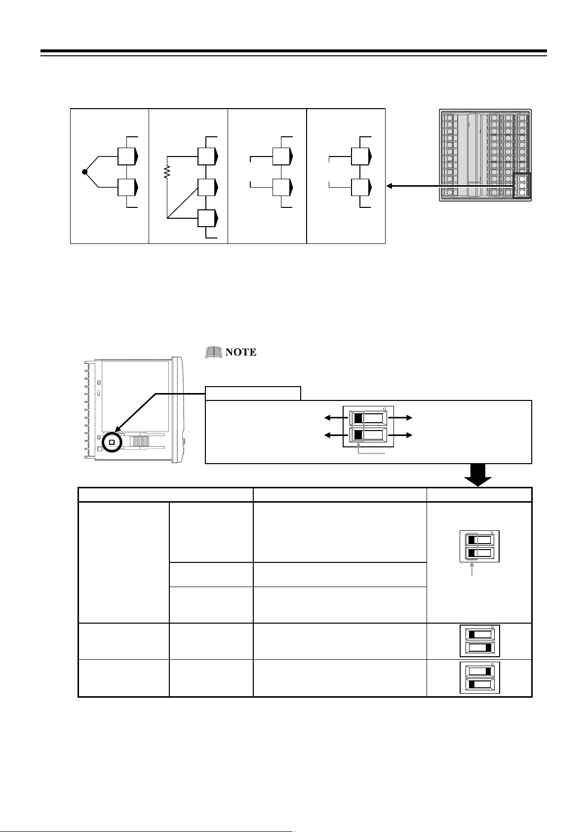
3. WIRING
t
IN
Measured input (TC/RTD/Voltage/Current) [universal input]
For the Measured input type, terminals 22 through 24 are allocated to the Measured input.
TC input Voltage input
RTD input
Current inpu
23
TC
24
B
A
22
RTD
23
IN
23
24
23
24
B’
24
Select the Voltage (low) input group, the Voltage (high) input group or the Current input group to
conform to the input type to be set.
How to switch Input group:
Switch the input group by using the upper Input select switch at the bottom left of the left side of this
instrument. Select the voltage input or the current input by using the lower input select switch (refer to
the description below).
Side view
To avoid damage to the instrument, disconnect measurement
input terminals before switching input groups.
Input select switch
Voltage (low) input group
Voltage (high) input group
Current input Voltage input
Input select switch (Dip switch)
Input group Input type Input select switch
Voltage (low) input
group
Current input group Current input 0 to 20 mA DC, 4 to 20 mA DC
Voltage (high) input
group
TC input K, J, E, T, S, R, B, N (JIS-C1602-1995)
PLII (NBS)
W5Re/W26Re (ASTM-E988-96)
U, L (DIN43710-1985)
PR40-20 (ASTM-E1751-00)
RTD input Pt100 (JIS-C1604-1997)
JPt100 (JIS-C1604-1981 Pt100)
Voltage (low)
input
Voltage (high)
input
0 to 10 mV DC, 0 to 100 mV DC,
0 to 1 V DC, 10 to 10 mV DC,
100 to 100 mV DC, 1 to 1 V DC
0 to 5 V DC, 1 to 5 V DC, 0 to 10 V DC
5 to 5 V DC, 10 to 10 V DC
Input select switch
(Dip switch)
For TC input, use the appropriate compensation wire.
For RTD input, use low resistance lead wires with no difference in resistance between the three lead
wires.
To avoid noise induction, keep input signal wire away from instrument power line, load lines and
power lines of other electric equipment.
3-8
IMR02L04-E3
Page 41
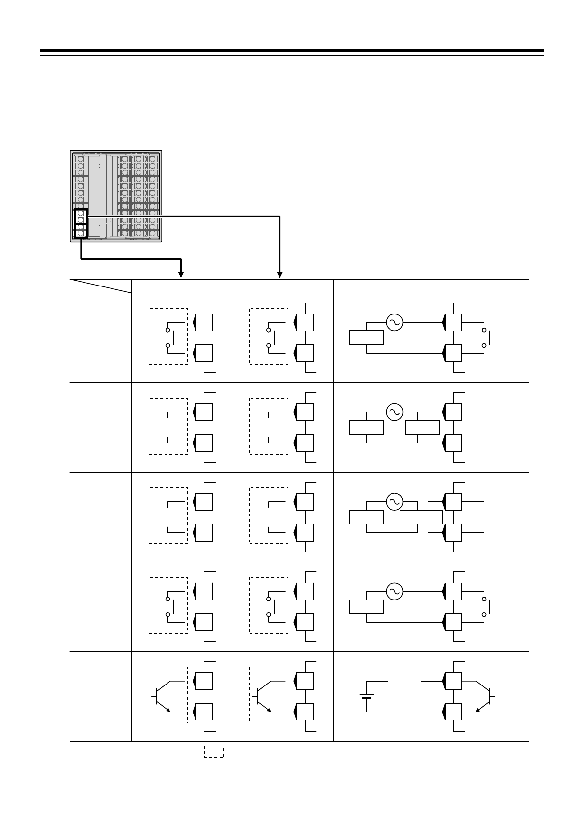
Output 1 (OUT1)/Output 2 (OUT2)
Number of outputs must be specified when ordering.
Terminal 11 and 12 are for output 1 (OUT1); Terminal 9 and 10 are for output 2 (OUT2).
Connect an appropriate load according to the output type. (Specify when ordering)
OUT1
Relay
contact
Voltage
pulse
Voltage,
Current
Triac
Open
collector
OUT2 (Specify when ordering)
OUT1 OUT2
OUT1
NO
OUT1
+
OUT1
+
OUT1
Triac
OUT1
11
12
11
12
11
12
11
12
11
12
: The dotted box diagram describes the output state of the instrument.
OUT2
NO
OUT2
+
OUT2
+
OUT2
Triac
OUT2
9
10
9
10
9
10
9
10
9
10
Load
Load
Load
Load
+
Wiring example
Actuator
Load
SSR
OUT1
11
NO
12
OUT1
11
0/12 V DC
12
OUT1
11
4 to 20 mA DC
12
OUT1
11
Triac
12
OUT1
11
12
3. WIRING
+
+
IMR02L04-E3
3-9
Page 42

3. WIRING
Number of outputs and output types must be specified when ordering. The specifications of each output
are as follows.
Specification
code
N
M
Output type Specifications
None
Relay contact
250 V AC 3 A (Resistive load)/30 V DC 1 A (Resistive load)
1a contact
0/12 V DC (Allowable load resistance: 600 or more)
V
Voltage pulse
Allowable load resistance is 300 or more (within 40 mA)
when using only OUT1.
4
5
6
7
8
Voltage
Current
0 to 5 V DC (Allowable load resistance: 1 k or more)
0 to 10 V DC (Allowable load resistance: 1 k or more)
1 to 5 V DC (Allowable load resistance: 1 k or more)
0 to 20 mA DC (Allowable load resistance: 600 or less)
4 to 20 mA DC (Allowable load resistance: 600 or less)
Output method: Zero-cross output
Allowable load current: 0.5 A
(Ambient temperature 40 C or less)
T
Triac
[Derating:
40
C or more.]
0.02 A/C when ambient is
Load voltage: 75 to 250 V AC
Minimum load current: 30 mA
ON voltage: 1.6 V or less
(at maximum load current)
Allowable load current: 100 mA
D
Open collector
Load voltage: 30 V DC or less
ON voltage: 2 V or less (at maximum load current)
Leakage current at OFF: 0.1 mA or less
Assign Control output, Transmission output or Event output as described in the table below.
Output terminal Details of output Setting screen
OUT1 Control output, Transmission output * Engineering mode F31.01:
OUT1 assignment (LoGC1)
[Refer to P. 4-36.]
OUT2 Control output, Transmission output or
Event output
Engineering mode F32.01:
OUT2 assignment (LoGC2)
[Refer to P. 4-36, 37.]
* Transmission output of OUT1 is only available for Output program.
Refer to the description below for general output assignment for each control action.
Control action Details of assignment
PID control OUT1: Control output: Manipulated output value 1 (MV1)
(reverse action or direct action)
OUT2: Transmission output or Event output
Heat/Cool PID control OUT1: Control output: Manipulated output value 1 (MV1) [heat-side]
OUT2: Control output: Manipulated output value 2 (MV2) [cool-side]
Position proportioning
PID control without FBR
OUT1: Control output: Manipulated output value 1 (MV1)
[open-side output]
OUT2: Control output Manipulated output value 2 (MV2)
[close-side output]
Make sure to assign the output as described for the Position proportioning
PID control.
3-10
IMR02L04-E3
Page 43

Output 3 (OUT3)
Number of outputs must be specified when ordering.
Terminal 47 and 48 are for OUT3.
Connect an appropriate load according to the output type. (Specify when ordering)
OUT3
+
47
48
Number of outputs and output types must be specified when ordering. The specifications of each output
are as follows.
Specification
code
N
V
3
4
5
6
7
8
D
Assign Control output, Transmission output or Event output at OUT3 assignment (LoGC3). *
OUT3 (Specify when ordering)
OUT3
+
47
48
: The dotted box diagram describes the output state of the instrument.
OUT3
47
Recorder
48
Output type Specifications
None
Voltage pulse
0/12 V DC (Allowable load resistance: 600 or more)
0 to 1 V DC (Allowable load resistance: 1 k or more)
Voltage
0 to 5 V DC (Allowable load resistance: 1 k or more)
0 to 10 V DC (Allowable load resistance: 1 k or more)
1 to 5 V DC (Allowable load resistance: 1 k or more)
Current
0 to 20 mA DC (Allowable load resistance: 600 or less)
4 to 20 mA DC (Allowable load resistance: 600 or less)
Allowable load current: 100 mA
Open collector
Load voltage: 30 V DC or less
ON voltage: 2 V or less (at maximum load current)
Leakage current at OFF: 0.1 mA or less
Wiring example Voltage pulse Voltage/Current Open collector
+
47
4 to 20 mA DC
48
3. WIRING
AO
+
* Refer to P. 4-37.
IMR02L04-E3 3-11
Page 44
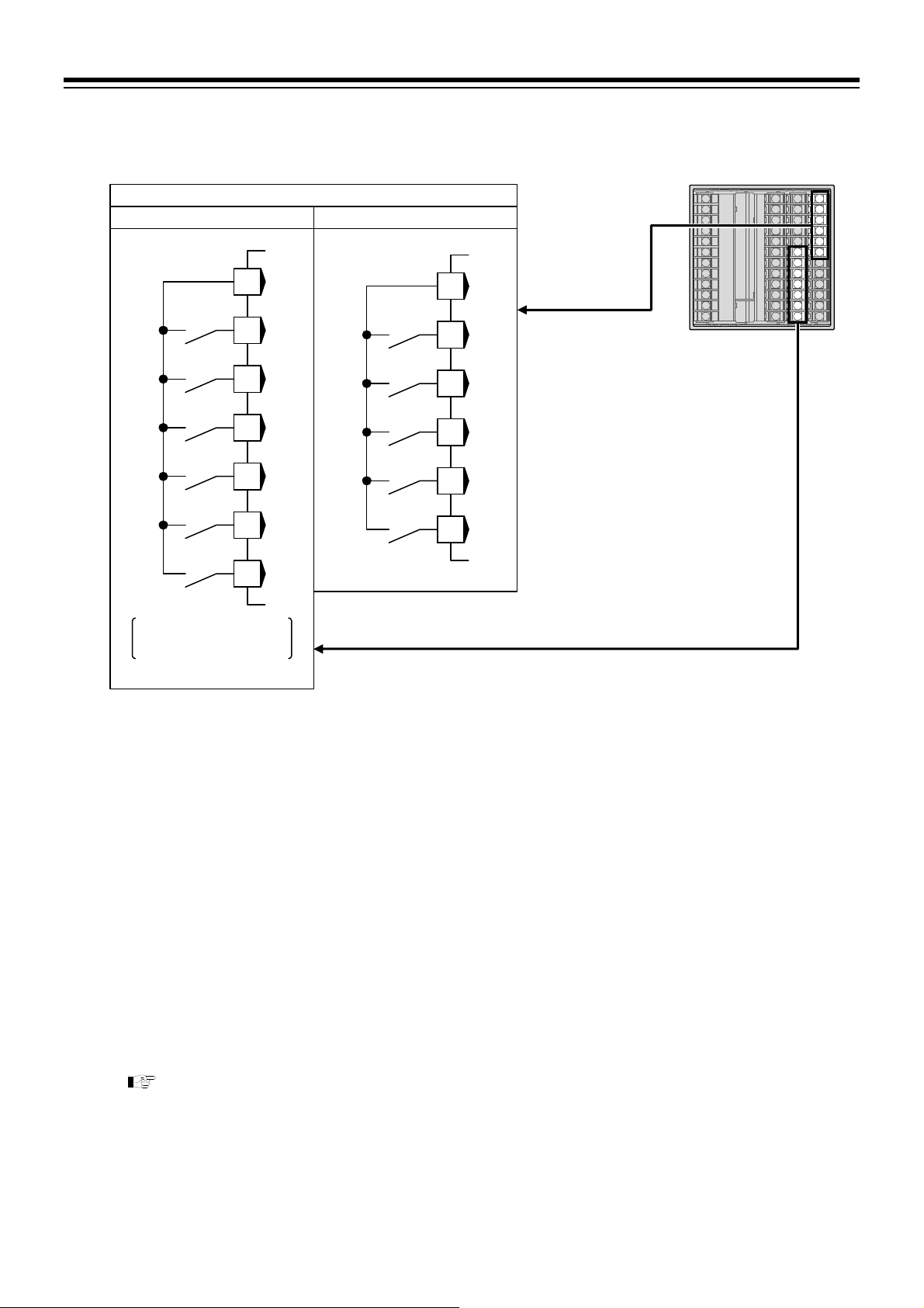
3. WIRING
Digital input 1 to 11 (DI1 to DI6 [optional], DI7 to DI11 [standard])
Terminals 30 through 36 for DI1 to DI6; and Terminals 13 through 18 for DI7 to DI11.
COM ()
DI1
DI2
DI3
DI4
DI5
DI6
Specification code:
1, 4, 5, W, X, Y or D
Digital input from external devices or equipment should be dry contact input. If it is not dry contact
input, the input should have meet the specifications below.
Contact specifications: At OFF (contact open): 10 kΩ or more
At ON (contact closed): 1 kΩ or less
Contact current: 5 mA or less
Capture judgment time: Approx. 200 ms + 1 sampling cycle
The following functions can be assigned to Digital inputs. (Can be specified when ordering.)
Reset mode (RESET) setting
Program control mode (RUN) setting
Step function (STEP)
Hold function (HOLD)
Direct/Reverse action switching
Wait state release
Pattern number switch
Pattern increment
For DI assignment, refer to 6.1.9 Digital input (DI) of the PF900/PF901 Instruction Manual
(IMR02L03-E) on the CD-ROM.
Dry contact input
30
31
32
33
34
35
36
DI7 to DI11 DI1 to DI6
COM ()
DI7
DI8
DI9
DI10
DI11
13
14
15
16
17
18
DI7 to DI11
DI1 to DI6 (optional)
3-12
IMR02L04-E3
Page 45

Digital output 1 to 4 (DO1 to DO4) [standard]
With DO optional, terminals 3 through 5 (DO3, DO4) and 6 through 8 (DO1, DO2) are allocated to the
DO.
DO1/DO2
DO1/DO2
COM
DO2
DO1
NO
NO
Specification code:
4 or C
Output type is only relay contact output.
Contact type: 1a contact
Contact rating (Resistive load): 250 V AC 1 A, 30 V DC 1 A
Electrical life: 300,000 times or more (Rated load)
Assign Event type at the setting screen below.
Digital output terminal Setting screen
DO1 Engineering mode F34.01: DO1 assignment (Ldo1) [Refer to P. 4-38.]
DO2 Engineering mode F34.02: DO2 assignment (Ldo2) [Refer to P. 4-38.]
DO3 Engineering mode F34.03: DO3 assignment (Ldo3) [Refer to P. 4-38.]
DO4 Engineering mode F34.04: DO4 assignment (Ldo4) [Refer to P. 4-38.]
DO3/DO4
6
7
8
DO3/DO4 Wiring example
COM
NO
DO4
NO
DO3
Specification code:
4 or C
: The dotted box diagram describes the output state of the instrument.
3
4
5
Load
Load
COM
3
4
5
3. WIRING
NO
DO2
NO
DO1
IMR02L04-E3
3-13
Page 46

3. WIRING
Digital output 5 to 12 (DO5 to DO12) [optional]
With DO optional, terminals 37 through 41 (DO5 to DO8) and 42 through 46 (DO9 to DO12) are
allocated to the DO.
DO5 to DO8 (optional)
DO5 to DO8 DO9 to DO12 Wiring example
COM ()
DO5
DO6
DO7
DO8
Specification code:
A or C
Output type is only open collector output.
Output method: Sink type
Allowable load current: 100 mA
Load voltage: 30 V DC or less
ON voltage: 2 V or less (at maximum load current)
Leakage current at OFF: 0.1 mA or less
Assign Event type at the setting screen below.
Digital output terminal Setting screen
DO5 Engineering mode F34.05: DO5 assignment (Ldo5) [Refer to P. 4-38.]
DO6 Engineering mode F34.06: DO6 assignment (Ldo6) [Refer to P. 4-38.]
DO7 Engineering mode F34.07: DO7 assignment (Ldo7) [Refer to P. 4-38.]
DO8 Engineering mode F34.08: DO8 assignment (Ldo8) [Refer to P. 4-38.]
DO9 Engineering mode F34.09: DO9 assignment (Ldo9) [Refer to P. 4-38.]
DO10 Engineering mode F34.10: DO10 assignment (Ldo10) [Refer to P. 4-38.]
DO11 Engineering mode F34.11: DO11 assignment (Ldo11) [Refer to P. 4-38.]
DO12 Engineering mode F34.12: DO12 assignment (Ldo12) [Refer to P. 4-38.]
DO9 to DO12 (optional)
37
38
39
40
41
DO9
DO10
DO11
DO12
: The dotted box diagram describes the output state of the instrument.
COM ()
Specification code:
A or C
42
43
44
45
46
+
Load
Load
Load
Load
37
38
39
40
41
COM ()
DO5
DO6
DO7
DO8
3-14
IMR02L04-E3
Page 47

Current transformer (CT) input/Feedback resistance (FBR) input
[optional]
With CT input or FBR input, terminals 19 through 21 are allocated to the specified input.
When using CT input, connect CTs to the relevant terminals.
CT: CTL-6-P-N [input range 0 to 30 A] (sold separately)
CTL-12-S56-10L-N [input range 0 to 100 A] (sold separately)
When CT type is not specified at ordering, the factory set value of the CT ratio is “800.” To use
CTL-12-S56-10L-N, change the set value of CT ratio into “1000” at the setting screen described below.
CT input terminal Setting screen
CT1 Engineering mode F45.01: CT1 ratio (CTR1) [Refer to P. 4-40.]
CT2 Engineering mode F46.01: CT2 ratio (CTR2) [Refer to P. 4-40.]
When using FBR input, connect a potentiometer to the relevant terminals.
CT input (1 point)
CT1
19
20
21
Specification code: T
Quick start code 2 (Initial
setting code): P or S
CT1/CT2/FBR (optional)
CT input (2 points) FBR input
COM
CT1
CT2
Specification code: T
Quick start code 2 (Initial
setting code): T or U
19
20
21
Allowance resistance:
Standard 135
(Availability: 100 to 10 k)
O
19
W
20
C
21
O: OPEN
W: WIPE
C: CLOSE
Specification code: F
3. WIRING
IMR02L04-E3
3-15
Page 48

3. WIRING
Communication 1/Communication 2 [optional]
With Communication function, terminals 25 through 29 are allocated to Communication.
Before wiring, confirm the proper terminals to be used for the communication interface being specified.
For wiring, refer to 7.1 Connections of the PF900/PF901 Instruction Manual (IMR02L03-E) on the
CD-ROM.
[Communication 1]
RS-232C
SG
25
SD
26
RD
27
Specification code: 1
Quick start code 2
(Initial setting code):
1 or 2
RS-232C [Communication 1]
RS-485 [Communication 2]
RS-232C
[Communication 1]
RS-485
[Communication 2]
Specification code: W
Quick start code 2 (Initial setting
code): 1 or 2
(Only Communication 1)
Communication 2 (RS-485) is for intercontroller communication.
[Communication 1]
RS-422A
SG
T (A)
T (B)
R (A)
R (B)
Specification code: 4
Quick start code 2
(Initial setting code):
1 or 2
25
SG
26
SD
27
RD
T/R (A)
T/R (B)
28
29
[Communication 1]
RS-485
25
26
27
28
29
RS-485 [Communication 1]
RS-485 [Communication 2]
[Communication 1]
RS-485
[Communication 2]
Specification code: X
Quick start code 2 (Initial setting
code): 1 or 2
(Only Communication 1)
T/R (A)
T/R (B)
Specification code: 5
Quick start code 2
(Initial setting code):
1 or 2
RS-485
SG
T/R (A)
T/R (B)
T/R (A)
T/R (B)
25
26
27
SG
25
26
27
28
29
Communication 1/
Communication 2
(optional)
RS-485
[Communication 2]
SG
T/R (A)
T/R (B)
Specification code: Y
(For Intercontroller
communication)
25
28
29
3-16
For the intercontroller communication, refer to 6.7 Intercontroller Communication Function
of the PF900/PF901 Instruction Manual (IMR02L03-E) on the CD-ROM.
IMR02L04-E3
Page 49

A
r
r
4. BASIC OPERATION
4.1 Operation Menu
4.1.1 Mode switching
There are 5 setting modes. Switch mode by using the key, the
Power ON
Press the
while pressing
the
2 seconds or more.
key for
Press the
pressing the
Press the
Press the
while pressing the
key
Press
the
o
Input type/Input range Display
(Refer to P. 4-2)
(in 4 seconds)
key
SV setting & monitor mode
Set the Segment level or the
Segment time in progress, or
monitor parameters such as
PV, MV and the Remaining
time of pattern. Stay in this
mode during operation.
(Refer to P. 4-9)
key while
key
or
key
Parameter setting mode
Create program pattern, set the
parameters such as PID and
Event, or set the parameters
for program setting such as the
time signal.
(Refer to P. 4-16)
key
key
Engineering mode
Initialize the parameters
related to input, output and
Event to conform to the usage
condition in the field.
Press the key while
pressing the
2 seconds or more.
(Refer to P. 4-32)
utomatically
Press and hold
the
for 2 seconds or more.
key
Press the
pressing the
Press the
Press and hold the key
for 2 seconds or more.
Press and hold
the
for 2 seconds
or more.
key fo
Press the
pressing the
Press the
key
or
Initial level engineering mode
Refer to the
Instruction Manual
(IMR02L03-E
PF900/PF901
)
on the CD-ROM.
Make sure to be in the RESET mode before conducting parameter setting in the Engineering
mode. It is possible to set parameters in the function block 10 (F10) and the function block 11
(F11) in the RUN mode, the FIX mode and the MAN mode.
It is also possible to go back to the SV setting & monitor mode by pressing the key while
pressing the
key.
key or the key.
key while
key
key
key while
or
key
key
Operation mode
Switch between PID and AT,
or operation modes (such as
Program control, Fixed set
point control, Manual control
and RESET).
(Refer to P. 4-14)
Press the key while
pressing the
Setup setting mode
Set the parameters such as
PV bias, Time proportional
cycle time, Heater break
alarm (HBA) set value and
communication (optional).
(Refer to P. 4-29)
Press the
pressing the
2 seconds or more.
Press and hold the key for 2 seconds or
more while pressing the
key to go to the Initial level engineering
mode from the SV setting & monitor mode,
the Parameter setting mode or the Setup
setting mode.
Parameters of the Initial level engineering
mode display during the parameter setting
of the Engineering mode.
key while
key for
key and the
key.
IMR02L04-E3 4-1
Page 50

4. BASIC OPERATION
A
A
4.1.2 Input type and input range display
This instrument immediately confirms inputs type symbol and input range following power ON.
Example: When sensor type is K thermocouple
SV setting & monitor mode
Power ON
PV
00INP
M:S
SV
000000000$0K
AT TS
PTN
00
SEG
00
utomatically
(in 2 seconds)
PV
RANGE
M:S
SV
-2000001372
AT TS
PTN
00
SEG
00
utomatically
(in 2 seconds)
(PV/SV monitor)
PV
00028
M:S
SV
$
500:00000000
AT TSDO
PT
2
SE
00
3
00
Symbol
Input type symbol (Refer to table 1)
Unit for input and SV display:
Celsius: C
Fahrenheit: F
Voltage/Current: No display
Input range high
Input range low
Table 1: Input type symbol table
Symbol Input type
K
J
T
S
R
E
b
n
P
W
U
L
PR
Thermocouple K
Thermocouple J
Thermocouple T
Thermocouple S
Thermocouple R
Thermocouple E
Thermocouple B
Thermocouple N
Thermocouple PLII
Thermocouple W5Re/W26Re
Thermocouple U
Thermocouple L
Thermocouple PR40-20
PT
JP
V
I
RTD JPt100
Voltage (mV, V)
Current (mA)
Once power is restored to the instrument the operation mode will return as it was before the power
went OFF. The operation mode is displayed after the Input type and Input range.
[Factory set value: Reset mode (RESET)]
For the action at power ON, refer to 5.2 Operating Precautions (P. 5-7).
RTD Pt100
4-2
IMR02L04-E3
Page 51

4. BASIC OPERATION
4.2 Changing Set Value
Numeric value setting
The flashing digit indicates which digit can be set. Press key to go to a different digit. Every time the
shift key is pressed, the flashing digit moves.
Set value (SV) may be changed by pressing the
To store a new value for the parameter, always press the
parameter and the new value will be stored.
Press the STEP R.SET key to store the set value and return to the previous parameter setting display.
Example: Change the segment level (to 200 C) and the segment time (to 40 minutes) in the Program control
mode (RUN).
PV/SV monitor (Before changing)
PV
00175
M:S
SV
5 10:53000100
PV
M:S
0 20:000 00100
Store set value.
PV/SV monitor (After changing)
PV
M:S
5 39:57000200
Segment level
LEVEL
SV
00182
SV
$
Press twice.
$
Flashing
Segment level set value
PV
0TIME
M:S
SV
040:00000200
Set “4.”
$
Parameter symbol
PV
LEVEL
M:S
0 20:000 00100
Press twice.
SV
key or the key.
key. The display changes to the next
Press twice.
$
Shifts flashing place.
PV
0TIME
M:S
SV
020:00000200
Shifts flashing place.
PV
LEVEL
M:S
SV
$
0 20:000 00200
Three times
PV
M:S
020:00000200
Store set value.
Set “2.”
Segment time
0TIME
SV
Flashing
Segment time
set value
IMR02L04-E3
Display returns to the PV/SV monitor display without storing set value being changed if the
key is not pressed within 1 minute. The new set values being set will not be stored when returning
to the PV/SV monitor display if the
key is pressed before pressing the key.
4-3
Page 52

4. BASIC OPERATION
The following is also available when changing the set value.
Increase SV from 199 °C to 200 °C:
1. Press the
(first digit from the right).
2. Press the
The display changes to 200.
PV
Decrease SV from 200 °C to 190 °C:
Decrease SV from 200 C to –100 C:
LEVEL
M:S
030:000 00199
1. Press the
2. Press the
The display changes to 190.
PV
LEVEL
M:S
030:000 00200
key to flash the one place
key to change to 0.
$
SV
SV
key to flash the tens place.
key to change to 9.
$
PV
LEVEL
M:S
030:000 00200
PV
LEVEL
M:S
030:000 00190
SV
SV
$
$
1. Press the
2. Press the
The display changes to 100.
PV
LEVEL
M:S
030:000 00200
key to flash the hundreds place.
key (three times) to change to 1.
$
SV
PV
LEVEL
M:S
SV
$
030:000 -0100
4-4
IMR02L04-E3
Page 53

Setting item selection
Press the key or the key to switch setting item.
4. BASIC OPERATION
Press the
key or the key to store the set values being set and go to the next parameter setting
display.
Example 1: Switch operation mode from the Program control mode to the Fixed set point control mode.
PV/SV monitor
PV
00028
M:S
SV
5 30:00000200
2 seconds or more
$
Operation mode
transfer
PV
0 MODE
M:S
SV
FIX000RPROG
PV
0 MODE
M:S
FIX000REFIX
Program control mode
The display goes to
the next parameter.
SV
Displays the character
“FIX” for the Fixed set
point control mode.
Switch to the Fixed
set point control
mode.
Example 2: Conduct Autotuning (AT).
PV/SV monitor
PV
00028
M:S
SV
5 30:00000200
2 seconds or more
$
ration mode transfer
PV
M:S
FIX000RPROG
Op
0 MODE
SV
Three times
PV
0MATU
M:S
SV
FIX000RPPID
The display goes to
the next parameter.
Conduct AT.
PV
0MATU
M:S
SV
FIX000RPPAT
PID control
Displays the
character “AT.”
Example 3: Change communication speed 1 in the Setup setting mode.
PV/SV monitor
PV
00028
M:S
SV
5 30:00000200
Press the
pressing the
$
key while
key.
PV bias
PV
L0CPB
M:S
SV
FIX0000000.0
Several times
$
Communication speed 1
PV
0 BPS1
M:S
SV
FIX00019200
The display goes to
the next parameter.
Switches to
38400.
PV
0 BPS1
M:S
SV
FIX00038400
Displays the 38400
IMR02L04-E3
4-5
Page 54

4. BASIC OPERATION
PV
$
4.3 Operation of the Direct Keys
Direct key menu
Use 7 direct keys to switch operation mode or to conduct simple key operation at program in progress.
Operation mode switching
Switch operation mode by using the direct key and display the PV/SV screen of the operation mode in
progress. State display lamp is orange when the operation mode is in progress. State display lamp turns off
when Operation mode switching is not possible.
Key operation in the Program control mode (RUN)
HOLD key:
Press the HOLD key to stop progress of time in the Program control mode (RUN). To release the HOLD
state, press the HOLD key again.
STEP R.SET key:
The STEP R.SET key offers 2 functions: the STEP function and the R.SET function. The STEP function is
available for the PV/SV monitor state in the Program control mode. The R.SET function is validated in the
Parameter setting mode.
STEP function (STEP lamp lights):
Forward the segment of the program pattern in process to the next.
R.SET function (R.SET lamp lights):
Go back to the previous parameter setting display (opposite action to the
parameter is stored when pressing the R.SET key.
PTN END key:
The PTN END key offers 2 functions: the PTN function and the END function. The END function is
available for the program setting in the Parameter setting mode. The PTN function is available only in the
Reset mode (RESET).
END function (END lamp lights):
Press the END key to display the program end screen when setting parameters related to segment at the
Program setting block in the Parameter setting mode. Then press the
display of pattern setting. Press the END key instead of the
screen.
PTN function (PTN lamp lights):
Switch to the Execution pattern selection display.
28
STEP R.SET
!
PTN
PTN END
RESET RUN
FIX MAN
HOLD
STEPR.SET
State display lamp
END
Direct key
H:M:S SV
TM
PTN
1
SEG
1
RESET
MONI MODE
PF900
0:00 0
DO
RUN
FIX MA N HOLD
SET
The operation mode cannot be switched by using the direct keys when RESET or RUN of the
Digital input (DI) is ON (contact closed).
Direct key Operation mode State display lamp Display
RESET Reset mode RESET lamp lights [Orange]
RUN Program control mode RUN lamp lights [Orange]
FIX Fixed set point control mode FIX lamp lights [Orange]
PV/SV monitor of
operation mode
MAN Manual control mode MAN lamp lights [Orange]
The HOLD key is not operative when conducting HOLD (contact closed) by using the Digital input
(DI).
key). The set value of the
key to go to the parameter setting
key to go back to the segment setting
4-6
IMR02L04-E3
Page 55

4. BASIC OPERATION
Direct key type
To prevent error in key operation, select direct key type at the function block 11 in the Engineering mode
(P. 4-33).
Type:
Invalidated: Direct key operation is invalidated
Press once: Operate the direct key by pressing once.
Press twice: Press the direct key once and confirm the state display lamp flashes in green. Then press
again within 3 seconds to operate.
Press and hold: Press and hold the direct key for 2 seconds to operate.
Direct key type is not available for the PTN END key (Press one type only).
The factory set value of the STEP R.SET key is “Press and hold” but the key type switches to
“Press once” when the R.SET function is operative. The factory set value of the other direct keys is
“Press once.”
Setting procedure
PV/SV monitor
PV
00028
M:S
SV
5 30:00000200
Press the key while
pressing the
2 seconds.
$
key for
Function block 10 (F10.)
PV
F10.
M:S
SV
FIX000RDISP
(Return to PV/SV monitor)
Parameter of the F11.02 to F11.06
F11.02: RUN key type
F11.03: FIX key type
F11.04: MAN key type
F11.05: HOLD key type
F11.06: STEP key type
Refer to the data range of the RESET key
type to set values for the keys.
(P. 4-32) (P. 4-33)
Function block 11 (F11.)
PV
F11.
M:S
SV
FIX000RDKEY
RESET key type
PV
KTYP1
M:S
SV
F11.01R 00001
Type
00000: Invalidated
00001: Press once
00002: Press twice
00003: Press and hold
IMR02L04-E3
4-7
Page 56

4. BASIC OPERATION
4.4 Protecting Setting Data
Prevent error in key operation by using the Set data lock function.
Parameter setting is prohibited when the Set data lock function is selected (except for the Operation mode
transfer, the Set data lock and the Execution pattern selection).
Setting procedure
Lock or unlock the key operation at the Set data lock setting display in the Operation mode.
PV/SV monitor
PV
00028
M:S
SV
5 30:00000200
PV/SV monitor
PV
00028
M:S
5 30:00000200!
It is possible to monitor set value of parameters.
Communication may be used to set parameters when the key operation is locked.
2 seconds or more
$
SV
$
Displays ! symbol when
the key operation is locked.
Operation mode
transfer
PV
0 MODE
M:S
SV
FIX000RPROG
(P. 4-14)
(Set data lock state)
Several times
PV
S LOCK
M:S
FIX000RE0ON
Set data lock
PV
S LOCK
M:S
SV
FIX000REOFF
SV
Displays the
character “ON.”
Unlock state
4-8
IMR02L04-E3
Page 57

4. BASIC OPERATION
4.5 Parameter Description
Parameters are described by Mode type, Parameter list with Data range and Parameter switching diagram.
Reference page list
Mode type
4.5.1 SV setting monitor mode
4.5.2 Operation mode
4.5.3 Parameter setting mode
4.5.4 Setup setting mode
4.5.5 Engineering mode
SV setting mode
Monitor mode
Partial setting type *
Batch setting type *
Parameter list Parameter switching
P. 4-9 P. 4-10, P. 4-11
P. 4-12 P. 4-13
P. 4-14 P. 4-15
P. 4-17 to P. 4-21 P. 4-22 to P. 4-25
P. 4-26 P. 4-27, P. 4-28
P. 4-29, P. 4-30 P. 4-31
P. 4-32 to P. 4-43 P. 4-44 to P. 4-49
Initial level engineering mode Refer to the PF900/PF901 Instruction manual
on the CD-ROM.
* For Partial setting type and Batch setting type, refer to Setting type for Program pattern (P. 4-16).
4.5.1 SV setting & monitor mode
Reference page
Set the parameters such as the Segment level and Segment time in progress or switch the Execution pattern
selection screen, monitor screen of the Pattern remaining time, Manipulated output value (MV) etc.
SV setting mode
Setting parameter varies with the operation mode (RESET, RUN, FIX, MAN) in the SV setting mode.
PV/SV monitor
Press the
(Each operation mode)
Press the
Press the PTN END key
(At RESET mode)
(At MAN mode)
Refer to P. 4-10 and P. 4-11 to switch parameter setting display.
Parameter list
Name Symbol Data range
Set value (SV) in Reset mode
Execution pattern selection
Segment level
Segment time
Set value (SV) in Fixed set point
control mode
key or the
key
Setting parameters of each
Operation mode
Execution pattern selection
key
Setting of the manual manipulated
output value
Reset mode (RESET)
SV
PTN
LEVEL
TIME
Fixed set point control mode (FIX)
SV
Setting limiter low to Setting limiter high 0
1 to 99 (Within the maximum pattern number) 1
Program control mode (RUN)
Setting limiter low to Setting limiter high 0
From 0:00 to 500:00 (Hour: Minute), or
from 0:00 to 500:00 (Minute: Second)
Setting limiter low to Setting limiter high 0
(PV/SV monitor)
Press the
Returns to the PV/SV monitor
Press the
key
key
Factory set
00 minute
value
0 hour
Continued on the next page.
IMR02L04-E3 4-9
Page 58

4. BASIC OPERATION
)
r
Continued from the previous page.
Name Symbol Data range
Manual manipulated output value
Set value (SV) in Manual control mode
Parameter switching
Reset mode (RESET)
Manual control mode (MAN)
MV
SV
PID control or Position proportioning PID control (With
FBR input):
Output limiter low to Output limiter high
Heat/Cool PID control:
(Cool-side output limiter (hig h)) to + (Heat-side o utput
limiter (high))
For overlap: 105.0 to +105.0 % *
* Actual output value is limited by the output limiter function.
Setting limiter low to Setting limiter high 0
Factory set
value
5.0
Press the
PV
M:S
MVX00000200
Execution pattern selection
Switch the PV/SV monitor display to the setting display of the Execution pattern selection by using the PTN
END key (PTN lamp lights) in the Reset mode (RESET).
Select Execution pattern number by using the
PV
M:S
530:00000200
Program control mode (RUN)
key to go to the Set value (SV) setting display in the Reset mode.
Set value (SV)
PV/SV monitor
00028
SV
$
Execution pattern number can be selected only in the Reset mode (RESET).
PV/SV monitor
(Reset mode)
00028
SV
$
PTN END
in Reset mode
PV
000SV
M:S
SV
$
FIX00000200
key or the key.
Execution pattern
selection
PV
00PTN
M:S
SV
Set value (SV
FIX00000001
Pattern numbe
Tag name setting will enable the display to show a tag name instead of the Pattern number.
Refer to 6.12 Tag Function (P. 6-31) for Tag name.
Press the
the segment time.
PV/SV monitor
PV
M:S
5 30:00000200
4-10
key in the Program control mode (RUN) to go to the setting display for the segment level and
Segment time
PV
0TIME
M:S
SV
030:00000200
IMR02L04-E3
00028
SV
Segment level
PV
$
LEVEL
M:S
SV
$
0 30:00000200
Set value
Page 59

)
)
Fixed set point control mode (FIX)
4. BASIC OPERATION
Press the
PV
M:S
FIX00000200
Manual control mode (MAN)
Set Manipulated output value by using the
Manual control mode (MAN). Press the
control mode.
PV
M:S
MVX0000020.0
key in the Fixed set point control mode (FIX) to go to the Set value (SV) setting display.
PV/SV monitor
00028
SV
$
Fixed set point control mode
PV
M:S
FIX00000200
PV/SV monitor
00028
SV
$
Manipulated output value may be set by using the key or the key.
The Set value (SV) set in the previous mode is taken over when switching to the Manual control
mode. However, the SV being changed in the Manual control mode is not affected when changing
to the other modes.
in Manual control mode
PV
M:S
FIX00000200
Set value (SV) in
000SV
SV
$
Set value (SV
key or the key at the PV/SV monitor display in the
key to go to the Set value (SV) setting display in the Manual
Set value (SV)
000SV
SV
$
Set value (SV
IMR02L04-E3
4-11
Page 60

4. BASIC OPERATION
Monitor mode
The contents of the monitor display are same in any operation mode (RESET, RUN, FIX, MAN).
PV/SV monitor
Press the
Press the direct key (RUN, FIX, MAN or RESET) of the operation mode in
progress to go back to the PV/SV monitor display from monitor screens.
Refer to P. 4-13 to switch parameter setting display.
Parameter list
Name Symbol Data range
Pattern remaining time monitor
Segment repeat remaining time/
execution time monitor
Pattern repeat remaining time/
execution time monitor
Total pattern remaining time/
execution time monitor
Wait condition monitor
Event state monitor
Time signal state monitor
Current transformer 1 (CT1) input
value monitor
Current transformer 2 (CT2) input
value monitor
Manipulated output value 1 (MV1)
[heat-side] monitor
Manipulated output value 2 (MV2)
[cool-side] monitor
1
Execution ti me monitor can be displayed by setting Repeat remaining process/program progression display at F10.12 in the Initial
level engineering mode. For Initial level engineering mode, refer to the PF900/PF901 Instruction manual (IMR02L03-E) on
the CD-ROM.
2
Displays only when CT input (optional) is specified. CT input value monitor displays CT input value as 1.1 times the average
current. CT input value is displayed for both Time proportional output and Current output. For Current output, the error of
measurement between actual current value and monitor display value becomes large when load factor is other than 0 % or 100 %.
3
Displayed when the Heat/Cool PID control is selected.
2
2
1
1
1
3
key
PTN.TM
RPT.SG
RPT.PN
RPT.PR
WAIT
EV
TS
CT1
CT2
MV1
MV2
Monitor mode
From 0:00 to 999:59 (Hour: Minute), or
from 0:00 to 999:59 (Minute: Second)
0 to 9999 times
0 to 10000 times
10000: No limit
0 to 10000 times
10000: No limit
Display: Not in wait state O Display: In wait state
OOO Value at SV display
Zone wait of the controller
Zone wait of the slave
Zone wait of the DI
Display: OFF O Display: ON
OOOOOOO Value at SV display
Event 1
Event 2
Event 3
Event 4
HBA1
HBA2
LBA
Display: OFF O Display: ON
OOOOOOOO Value at SV display
Time signal 1
Time signal 2
Time signal 3
Time signal 4
Time signal 5
Time signal 6
Time signal 7
Time signal 8
0.0 to 100.0 A
0.0 to 100.0 A
PID control, Heat/Cool PID control:
5.0 to 105.0 %
Position proportioning PID control:
0.0 to 100.0 % (Displays the
5.0 to 105.0 %
Press the
switch monitor display.
FBR input value)
key to
Factory set
value
4-12
IMR02L04-E3
Page 61

y
Parameter switching
Press the key to switch monitor screen.
Press the
progress.
The contents of the monitor display are same in any operation mode (RESET, RUN, FIX, MAN).
Press the direct key (RUN, FIX, MAN or RESET) of the operation mode in progress to go back to
the PV/SV monitor display from monitor screens.
Parameters will not be displayed if the relevant function is not activated or no relevant specification
is selected when ordering.
PV/SV monitor
PV
00028
M:S
SV
5 30:00000200
Pattern remaining
time monitor
PV
00028
M:S
SV
PTN.TM0053:20
Parameter symbol
Displays the remaining time
including the duration of the
Segment repeat.
Current transformer 1
(CT1) input value monitor
PV
00028
M:S
SV
CT10000007.0
Displays only when CT
input (optional) is
specified.
Current transformer 2
(CT2) input value monitor
PV
00028
M:S
SV
CT20000026.5
Displays only when CT
input (optional) is
specified.
key at the monitor screen to go to the SV setting mode of the operation mode in
$
Segment repeat
remaining time/
execution time monitor *
PV
$
Monitor
value
$
$
M:S
RPT.SG000200
* Execution time monitor can be displayed by setting
Repeat remaining process/program progression displa
at F10.12 in the Initial level engineering mode. For Initial
level engineering mode, refer to 4.5.6 Initial level
engineering mode of the PF900/PF901 Instruction
Manual (IMR02L03-E) on the CD-ROM.
Time signal state
PV
M:S
TS0 _____O_O
_ Display: Time signal OFF
O Display: Time signal ON
Manipulated output value 1
(MV1) [heat-side] monitor
PV
M:S
MV10000020.0
00028
SV
monitor
00028
SV
00028
SV
4. BASIC OPERATION
Pattern repeat
remaining time/
execution time monitor *
PV
$
00028
M:S
SV
$
RPT.PN000200
Event state monitor
PV
$
00028
M:S
SV
$
EV00______O
Display: Event OFF
O Display: Event ON
Manipulated output value 2
(MV2) [cool-side] monitor
PV
$
00028
M:S
SV
$
MV200000-5.0
Displayed when the Heat/Cool
PID control is selected.
Total pattern
remaining time/
execution time monitor *
PV
00028
M:S
SV
$
RPT.PR000200
Displays the remaining
time/execution time
including the numbers
of Link pattern.
Wait condition monitor
PV
00028
M:S
SV
$
WAIT0000__O
_ Display: Not in wait state
O Display: In wait state
Returns to the
PV/SV monitor
IMR02L04-E3
4-13
Page 62
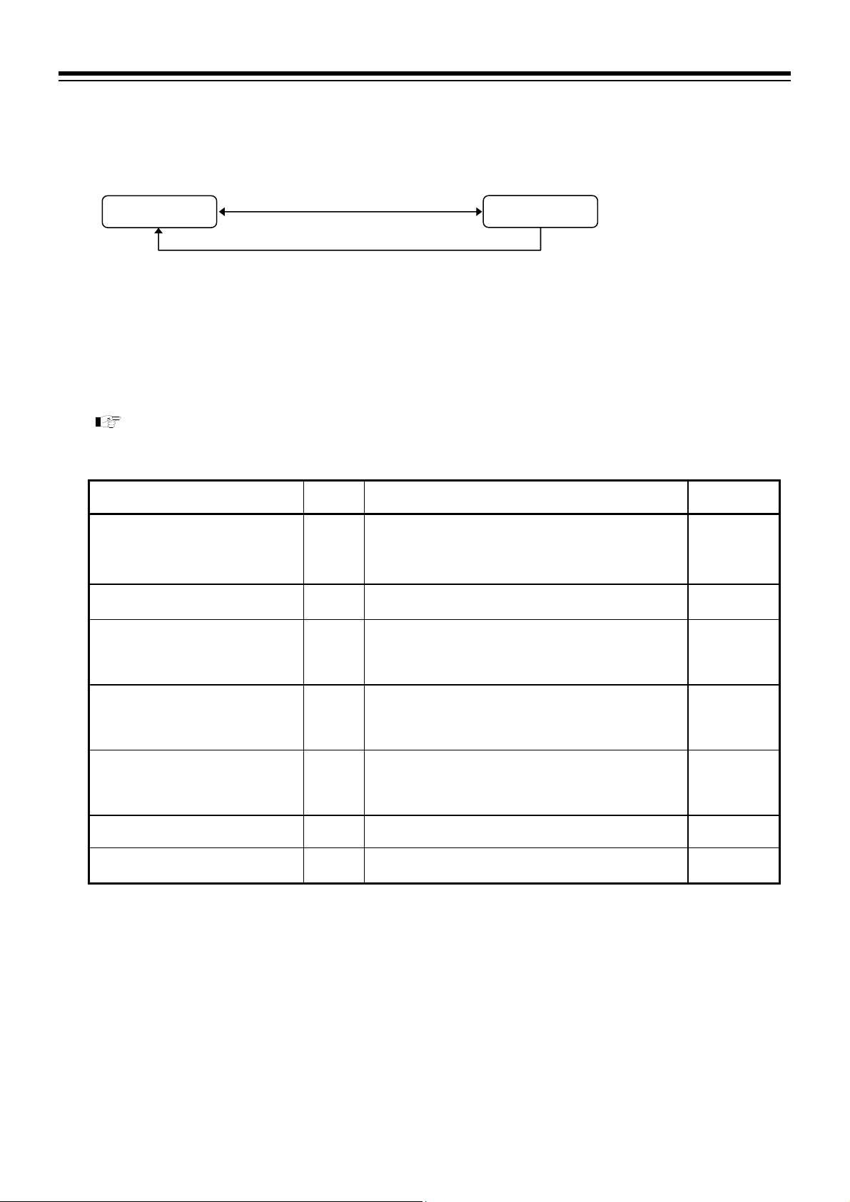
4. BASIC OPERATION
4.5.2 Operation mode
Set parameters such as PID/AT, and the operation mode (Program control, Fixed set point control, Manual
control, or RESET).
PV/SV monitor
Press and hold the
2 seconds or more.
key for
Operation mode
Press the key or Press the key while pressing the key.
Press the key to switch operation screen.
Press the STEP R.SET key to go back to the previous
display.
Press the STEP R.SET key while pressing the
to go back to the first parameter setting display
(Operation mode transfer).
Refer to P. 4-15 to switch parameter setting display.
Parameter list
key
Name Symbol Data range
Operation mode transfer
Step function
Search function
PID/AT transfer
Autotuning (AT) with learning
function
Interlock release
Set data lock
1
Operative only in the Program control mode (RUN) [Not available when the operation is in HOLD state or RUN of the Digital
input (DI) is ON (contact closed).]
2
Operative when the operation is in the Program control mode (RUN) and in the HOLD state [Not available during Autotuning
(AT).]
3
4
Operative when the operation is in the Program control mode (RUN) or in the Fixed set point control mode (FIX).
Operative only in the Reset mode (RESET)
MODE
STEP
SARCH
ATU
ATT
ILR
LOCK
RESET (Reset mode)
PROG (Program control mode)
FIX (Fixed set point control mode)
MAN (Manual control mode)
ON: Forward to the next segment in progress.
Turns OFF automatically when the Step function is completed.
ON: Search start
OFF: Search stop
Turns OFF automatically when the Search function is
completed.
PID: PID control
AT: Autotuning (AT) start
When the AT is finished, the control will automatically returns
to “PID control.”
ON: Autotuning (AT) with learning start
OFF: Autotuning (AT) with learning stop
Turns OFF automatically when the AT with learning function
is completed.
ON: Interlock
OFF: Interlock release
ON: Set data lock
OFF: Set data unlock
Factory set
value
RESET
OFF
OFF
PID
OFF
OFF
OFF
4-14
IMR02L04-E3
Page 63
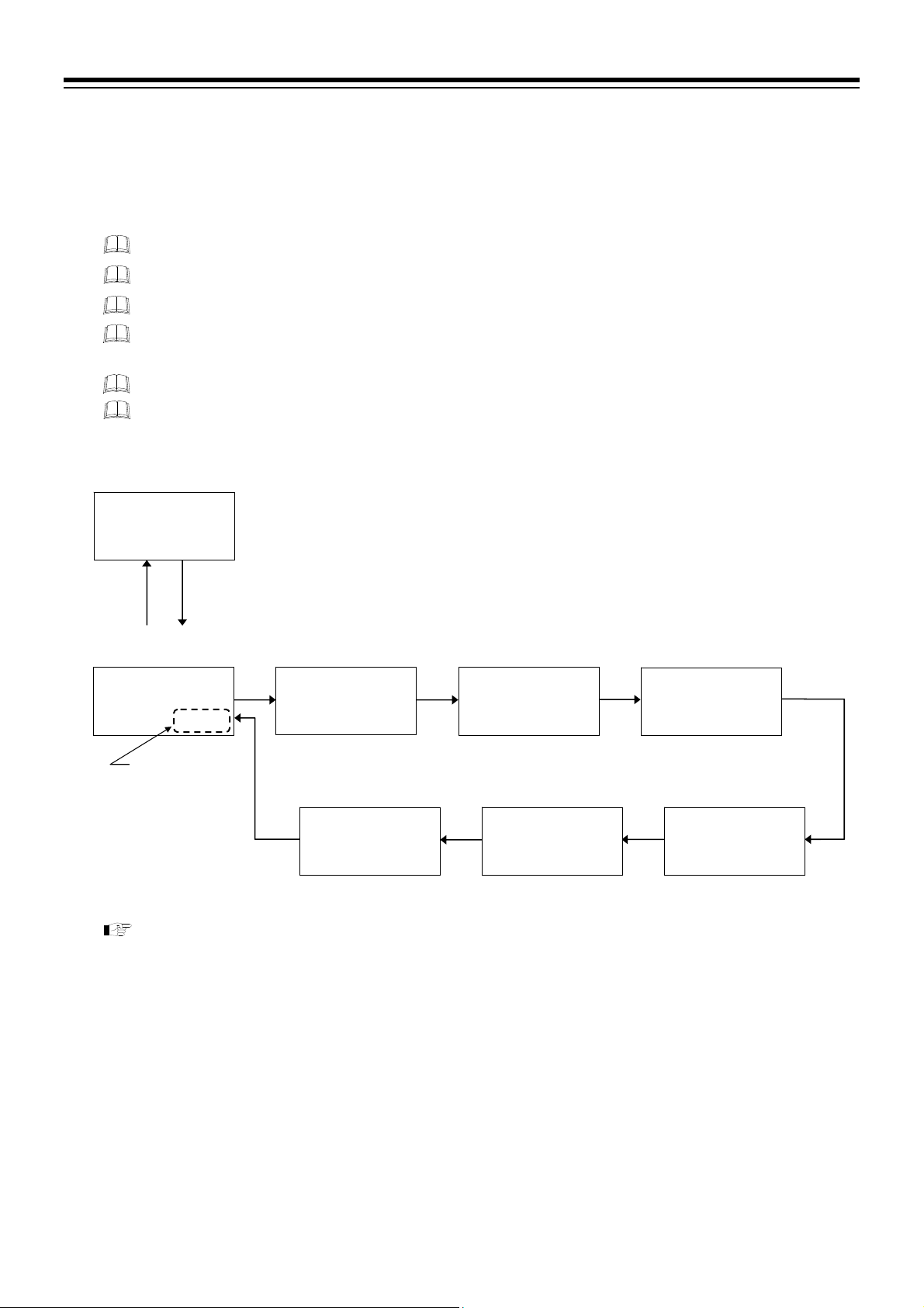
4. BASIC OPERATION
Parameter switching
Press and hold the key for 2 seconds or more at PV/SV monitor screen until Operation mode is
displayed.
Press the
key to switch operation screen.
It is possible to switch displays by using the
key instead of the key.
PV
M:S
5 30:00000200
PV
M:S
FIX000RPROG
Press the
Press the STEP R.SET key to go back to the previous display.
Press the STEP R.SET key while pressing the
display.
Display returns to the PV/SV monitor if no key operation is performed within 1 minute.
Parameters will not be displayed if the relevant function is not activated or no relevant specification
is selected when ordering.
PV/SV monitor
00028
SV
Operation mode
transfer
0 MODE
Select by using
the
the
Press and hold the key
for 2 seconds or more.
SV
key or
key.
For setting procedure of each function, refer to 6. FUNCTION AND SETTING PROCEDURE of
the PF900/PF901 Instruction Manual (IMR02L03-E) on the CD-ROM.
key to go back to the PV/SV monitor.
$
Step function
PV
0 STEP
M:S
SV
FIX000REOFF
Set data lock
PV
S LOCK
M:S
SV
FIX000REOFF
key to go back to the Operation mode transfer
Search function
PV
SARCH
M:S
SV
FIX000REOFF
Interlock release
PV
S0ILR
M:S
SV
FIX000REOFF
PID/AT transfer
PV
0SATU
M:S
SV
FIX000REPID
Autotuning (AT)
with learning function
PV
0SATT
M:S
SV
FIX000REOFF
IMR02L04-E3
4-15
Page 64

4. BASIC OPERATION
4.5.3 Parameter setting mode
Parameters are classified into 12 setting blocks such as Program setting block, PID memory group setting
block and Event memory group setting block in the Parameter setting mode. Setting block may be switched
by using the
key or the key.
Setting type for Program pattern
Partial setting or Batch setting is selectable for setting type of Program pattern in the Parameter setting mode.
To select the type, go to F80.03 (P.4-43) in the Engineering mode.
For parameter of the Engineering mode, refer to 4.5.5 Engineering mode (P. 4-32).
Partial setting type (Factory set value)
* Settable only when Segment signal is specified.
Validates when specifying Segment signal function.
Batch setting type
* Settable only when Segment signal is specified.
Validates when specifying Segment signal function.
Program setting block
Segment level
Segment time
Parameters for pattern
Partial setting type consists of Program setting block
Program memory group
setting block
and Program memory group setting block. Setting
block varies based on the parameters.
PID memory group number
Event memory group number
Wait memory group number
Segment signal *
Refer to P. 4-17 to 4-21 for Parameter list of the Partial setting type and P. 4-22 to 4-25 for
parameter switching.
Program setting block
Segment level
Segment time
Parameters for pattern
PID memory group number
Batch setting type consists of Program setting block
where all parameters related to Program pattern can be
set.
Event memory group number
Wait memory group number
Segment signal *
Refer to P. 4-26 for Parameter list of the Batch setting type and P. 4-27 to 4-28 for parameter
switching.
4-16
IMR02L04-E3
Page 65

Parameter list [Partial setting type]
4. BASIC OPERATION
PV/SV monitor
Press the key or Press the key while pressing the key.
For parameter switching, refer to P. 4-22 to 4-25.
Name Symbol Data range
Setting pattern number
Segment level
Segment time
Segment repeat start/end number
Segment repeat execution time
Pattern repeat execution time
Link pattern number
Pattern end output duration
Time signal memory group number
Output program memory group
number
Setting pattern number
PID memory group number
Event memory group number
Wait memory group number
Press and hold the key for
2 seconds or more.
Press the key to switch setting screen.
Setting block may be switched by using the
the
Press the STEP R.SET key to go back to the previous
display.
Press the STEP R.SET key while pressing the
to go back to the first setting display of the setting block.
Program setting block (
PTN.NO
LEVEL
TIME
ST‹ED
RPT.SG
RPT.PN
LNK.PN
END.TM
P TS.GR
P.MV.GR
Program memory group setting block (PR.MEM)
PTN.NO
PID.GR
EV.GR
WT.GR
1 to 99 (Within the maximum pattern number)
Setting limiter low to Setting limiter high
From 0:00 to 500:00 (Hour: Minute), or
from 0:00 to 500:00 (Minute: Second)
Start number: 1 to 99
End number: 1 to 99
Within the maximum segment number
1 to 9999 times
1: No segment repeat
1 to 10000 times
1: No pattern repeat
10000: No limit
0 to 99 (Within the maximum pattern number)
0: No pattern link
From 0:00 to 500:00 (Hour: Minute), or
from 0:00 to 500:00 (Minute: Second)
Output remains ON at 0:00 (Hour: Minute or
Minute: Second)
0 to 16
0: No assignment
0 to [128/Maximum number of segments]
Up to 99
0: No assignment
1 to 99 (Within the maximum pattern number)
0 to 8
0: Level PID
0 to 8
0: Event OFF
0 to 8
0: Wait OFF
Parameter setting mode
key.
PROG
key or
key
Factory set
value
)
1
0
0 hour
00 minute
1
1
1
0
0 hour
00 minute
1
0
1
0
1
1
IMR02L04-E3
Continued on the next page.
4-17
Page 66

4. BASIC OPERATION
Continued from the previous page.
Name Symbol Data range
Segment signal 1
PID memory group number
Proportional band [heat-side]
Integral time [heat-side]
Derivative time [heat-side]
Control response parameter
Proportional band [cool-side] 2
Integral time [cool-side] 2
Derivative time [cool-side] 2
Overlap/Deadband 2
Open/Close output neutral zone 3
Manual reset 4
Output limiter high (MV1)
Output limiter low (MV1)
1
Displayed when the Segment signal type is selected.
2
Displayed when the Heat/Cool PID control is selected.
3
Displayed when the Position proportioning PID control is selected.
4
Displayed when the P (Proportional) action is selected.
SIGNL
PID memory group setting block (
PID.GR
P
I
D
rPT
Pc
Ic
Dc
DB
YDB
MR
OLH
OLL
Factory set
value
0: OFF 1: ON
00000000 Value at SV display
Segment signal 1
Segment signal 2
Segment signal 3
Segment signal 4
Segment signal 5
Segment signal 6
Segment signal 7
Segment signal 8
)
PID
1 to 8
TC/RTD inputs:
0 (0.0, 0.00) to Input span (Unit: C [F])
Varies with the setting of the Decimal point position.
Voltage (V)/Current (I) inputs:
0.0 to 1000.0 % of Input span
0 (0.0, 0.00): ON/OFF action
PID control or Heat/Cool PID control:
0 to 3600 seconds or 0.0 to 3600.0 seconds
0 (0.0): PD action
Position proportioning PID control:
1 to 3600 seconds or 0.1 to 3600.0 seconds
Varies with the setting of the Integral/Derivative time decimal
point position selection.
0 to 3600 seconds or 0.0 to 3600.0 seconds
0 (0.0): PI action
Varies with the setting of the Integral/Derivative time decimal
point position selection.
0: Slow
1: Medium
2: Fast
P action and PD action, the con trol res ponse is fixed at 2 (Fast) .
TC/RTD inputs:
1 (0.1, 0.01) to Input span (Unit: C [F])
Voltage (V)/Current (I) inputs:
0.1 to 1000.0 % of Input span
0 to 3600 seconds or 0.0 to 3600.0 seconds
0 (0.0): PD action
Varies with the setting of the Integral/Derivative time decimal
point position selection.
0 to 3600 seconds or 0.0 to 3600.0 seconds
0 (0.0): PI action
Varies with the setting of the Integral/Derivative time decimal
point position selection.
TC/RTD inputs:
Input span to +Input span (Unit: C [F
Voltage (V)/Current (I) inputs:
100.0 to +100.0 %
Minus () setting results in Overlap.
However, the overlapping range is within th e proportion al range.
0.1 to 20.0 % 2.0
100.0 to +100.0 % 0.0
Output limiter low (MV1) to 105.0 % 105.0
5.0 % to Output limiter high (MV1) 5.0
])
00000000
1
TC/RTD: 30
V/I: 3.0
240
60
2
TC/RTD: 30
V/I: 3.0
240
60
0
Continued on the next page.
4-18
IMR02L04-E3
Page 67

4. BASIC OPERATION
Continued from the previous page.
Name Symbol Data range
Output limiter high (MV2) 1
Output limiter low (MV2) 1
ON/OFF action differential gap
(upper)
ON/OFF action differential gap
(lower)
Control loop break alarm (LBA) time 3
LBA deadband (LBD) 3
Event memory group number
Event 1 set value (EV1)
Event 1 set value (EV1) [high] 4
Event 1 set value (EV1') [low] 4
Event 2 set value (EV2)
Event 2 set value (EV2) [high] 4
Event 2 set value (EV2') [low] 4
Event 3 set value (EV3)
Event 3 set value (EV3) [high] 4
Event 3 set value (EV3') [low] 4
Event 4 set value (EV4)
Event 4 set value (EV4) [high] 4
Event 4 set value (EV4') [low] 4
Wait memory group number
Wait zone high
Wait zone low
Wait release trigger selection
1
2
3
4
2
2
Displayed when the Heat/Cool PID control is selected.
Displays when Proportional band [heat-side] is set to “0.”
Displays when LBA is specified.
This parameter displays when the event type is the Deviation High/Low (Individual high and low setting) or the Band (Individual
high and low setting).
OLH2
OLL2
OHH
OHL
LBA
LBD
Event memory group setting block (
EV.GR
EV1
EV1`
EV2
EV2`
EV3
EV3`
EV4
EV4`
Wait memory group setting block (
WT.GR
ZONE.H
ZONE.L
RE.TRG
Output limiter low (MV2) to 105.0 % 105.0
5.0 % to Output limiter high (MV2) 5.0
TC/RTD inputs:
0 (0.0, 0.00) to Input span (Unit: C [F
Voltage (V)/Current (I) inputs:
0.0 to 100.0 % of Input span
0 to 7200 seconds
0: Unused
0 to Input span 0
EVENT
1 to 8 1
Deviation:
Input span to Input span
Process and set value:
Input range low to Input range high
Manipulated output value (MV1 or MV2):
5.0 to 105.0 %
Input span to Input span
The data range is same as Event 1 set value (EV1). 50
The data range is same as Event 1 set value (EV1) [high]. 50
The data range is same as Event 1 set value (EV1') [low].
The data range is same as Event 1 set value (EV1). 50
The data range is same as Event 1 set value (EV1) [high]. 50
The data range is same as Event 1 set value (EV1') [low].
The data range is same as Event 1 set value (EV1). 50
The data range is same as Event 1 set value (EV1) [high]. 50
The data range is same as Event 1 set value (EV1') [low].
WAIT
1 to 8
TC/RTD inputs:
0 (0.0, 0.00) to 200 (200.0, 200.00) (Unit: C [F
Voltage (V)/Current (I) inputs:
0.0 to 20.0 % of Input span
0 (0.0, 0.00): Wait zone high becomes OFF
TC/RTD inputs:
200 (200.0, 199.99) to 0 (0.0, 0.00) (Unit: C [F
Voltage (V)/Current (I) inputs:
20.0 to 0.0 % of Input span
0 (0.0, 0.00): Wait zone low becomes OFF
0: Invalidate 1: Validate
00000 Value at SV display
Zone wait 1 (the controller)
Zone wait 2 (all slave controllers)
Wait release by digital input (DI)
Unused
])
)
)
])
])
Continued on the next page.
Factory set
value
TC/RTD: 1
V/I: 0.1
TC/RTD: 1
V/I: 0.1
480
50
50
50
50
50
50
1
0
0
00001
IMR02L04-E3
4-19
Page 68

4. BASIC OPERATION
Continued from the previous page.
Name Symbol Data range
Wait time-out set value
Time signal memory group number
Time signal output assignment
Start segment of time signal
Time signal start time
End segment of time signal
Time signal end time
Output program memory group setting block (
Output program memory group
number
Output program value 1 a
Output program value 2 b
Output program value 3 c
Level PID setting 1
Level PID setting 2
Level PID setting 3
Level PID setting 4
Level PID setting 5
Level PID setting 6
Level PID setting 7
Set value (SV) in Reset mode
Manipulated output value 1 (MV1) in
Reset mode
Manipulated output value 2 (MV2) in
Reset mode
Event memory group number in
Reset mode
Set value (SV) in Fixed set point
control mode
PID memory group number in Fixed
set point control mode
Event memory group number in
Fixed set point control mode
a
Displays when Output program value 1 is assigned to OUT1.
b
c
a
Displays when Output program value 2 is assigned to OUT2.
Displays when Output program value 3 is assigned to OUT3.
TM.OUT
Time signal memory group setting block (
P TS.GR
01.OUT
01.S.SN
01.S.TM
01.E.SN
01.E.TM
P.MV.GR
P.MV1
P.MV2
P.MV3
Level PID setting block (
LEVL.1
LEVL.2
LEVL.3
LEVL.4
LEVL.5
LEVL.6
LEVL.7
Reset mode setting block (
SV
MV1
MV2
EV.GR
Fixed set point control mode setting block (
SV
PID.GR
EV.GR
Factory set
value
From 0:00 to 500:00 (Hour: Minute), or
from 0:00 to 500:00 (Minute: Second)
0:00 (Hour: Minute or Minute: Second): Unused
TM.SIG
1 to 16
1 to 8: Time signal 1 to 8
0: No assignment
1 to 99
Within the maximum segment number.
From 0:00 to 500:00 (Hour: Minute), or
from 0:00 to 500:00 (Minute: Second)
1 to 99
Within the maximum segment number.
From 0:00 to 500:00 (Hour: Minute), or
from 0:00 to 500:00 (Minute: Second)
1 to [128/Maximum number of segments]
Up to 99
5.0 to 105.0 %
5.0 to 105.0 %
5.0 to 105.0 %
RESET
)
)
LV.PID
Input range low to Level PID setting 2
Level PID setting 1 to Level PID setting 3
Level PID setting 2 to Level PID setting 4
Level PID setting 3 to Level PID setting 5
Level PID setting 4 to Level PID setting 6
Level PID setting 5 to Level PID setting 7
Level PID setting 6 to Input range high
Setting limiter low to Setting limiter high 0
5.0 to 105.0 %
5.0 to 105.0 %
0 to 8
0: Event OFF
Setting limiter low to Setting limiter high 0
0 to 8
0: Level PID
0 to 8
0: Event OFF
)
PRG.MV
)
FIX
)
0 hour
00 minute
0 hour
00 minute
0 hour
00 minute
Input range
high
Input range
high
Input range
high
Input range
high
Input range
high
Input range
high
Input range
high
Continued on the next page.
1
0
1
1
1
5.0
5.0
5.0
5.0
5.0
1
0
1
4-20
IMR02L04-E3
Page 69

Continued from the previous page.
Name Symbol Data range
PID memory group number in
Manual control mode
Event memory group number in
Manual control mode
Pattern copy *
Data clear *
* Settable only in the Reset mode (RESET)
Manual control mode setting block (
PID.GR
EV.GR
COPY
CLR
0 to 8
0: Level PID
0 to 8
0: Event OFF
Editing block (
Copy source number: 0 to 99
Copy destination number: 0 to 99
Within the maximum pattern number.
All set values in the Parameter setting mode will be
initialized after setting 9999 and switching from NO to
YES.
EDIT
)
MAN
4. BASIC OPERATION
Factory set
value
)
0
1
0
0
IMR02L04-E3
4-21
Page 70

4. BASIC OPERATION
r
A
A
A
r
Parameter switching [Partial setting type]
Press and hold the key for 2 seconds or more at PV/SV monitor screen until Parameter setting mode is
displayed.
Press the
key to switch operation screen.
Switch setting block by using the
Press the
key to go back to the PV/SV monitor.
Press the STEP R.SET key to go back to the previous display.
Press the STEP R.SET key while pressing the
PV
M:S
5 30:00000200
setting block.
Display returns to the PV/SV monitor if no key operation is performed within 1 minute.
PV/SV monitor
00028
SV
$
Press and hold the key
for 2 seconds or more.
Program
setting block
PV
PROG
M:S
SV
30000000200
(P. 4-17)
Setting pattern
PV
PTN.NO
M:S
53000000001
PTN END
Press the STEP R.SET key
while press the
PV
M:S
RES00000001
PV
M:S
RES00000001
Program memory group
setting block
key or the key.
Setup setting mode
Press and hold the key
for 2 seconds or more.
number
SV
Release Program end to
go to the next segment
setting display.
key.
Segment repeat
execution time
RPT.SG
SV
Pattern repeat
execution time
RPT.PN
SV
key to go back to the first setting display of the
Segment level
PV
LEVEL
M:S
SV
5 30:00000200
Program end
PV
P P.END
M:S
SV
53000000001
Segment repeat
start/end number
PV
ST‹ED
M:S
SV
RES00001‹01
fter setting the Segment repeat start number, press the
key to set the Segment repeat end number.
Link pattern numbe
PV
LNK.PN
M:S
SV
RES00000000
Output program memory
group number
PV
P.M V.GR
M:S
SV
53000000000
Segment time
PV
$
L TIME
M:S
SV
030:00000200
Go to the setting display of
the next segment.
PTN END
Set Program end (to limit
the segment numbers).
fter setting the last segment
being set by the Program end.
fter setting all segments
being set at the Maximum
pattern/segment number in
the Engineering mode.
End number
Start numbe
PV
M:S
Pattern end output
duration
END.TM
RES000000:00
Time signal memory
group number
PV
P TS.GR
M:S
53000000001
SV
SV
4-22
IMR02L04-E3
Page 71

A
Program
setting block
SV
(P. 4-17)
Program memory group
setting block
PV
PR.MEM
M:S
30000000200
PID memory group
setting block
PV
PID
M:S
30000000200
SV
(P. 4-18)
Event memory group
setting block
PV
EVENT
M:S
SV
30000000200
(P. 4-19)
Wait memory group
setting block
Setting pattern
number
PV
PTN.NO
M:S
SV
53000000001
Go to the setting
display of the
next segment.
fter setting parameters
of all segments
PID memory group
number
PV
PID.GR
M:S
SV
53000000001
Event memory group
*
number
PV
P EV.GR
M:S
SV
53000000001
* Event memory group setting block does
not display when types of Event 1 to 4
are all set to “0: None.”
4. BASIC OPERATION
Press the STEP R.SET key to go back to the previous display.
Press the STEP R.SET key while pressing the
back to the first setting display of the setting block.
PID memory group
number
PV
PID.GR
M:S
SV
53000000000
Segment signal
PV
SIGNL
M:S
SV
RES00000000
(Displays when the Segment
signal is selected.)
Setting parameters in the PID memory group
P: Proportional band [heat-side]
I: Integral time [heat-side]
D: Derivative time [heat-side]
rPT: Control response parameter
Pc: Proportional band [cool-side]
Ic: Integral time [c ool-side]
Dc: Derivative time [cool-side]
DB: Overlap/Deadband
YDB: Open/Close output neutral zone
MR: Manual reset
OLH: Output limiter high (MV1)
OLL: Output limiter low (MV1)
OLH2: Output limiter high (MV2)
OLL2: Output limiter low (MV2)
OHH: ON/OFF action differential gap (upper)
OHL: ON/OFF action differential gap (lower)
LBA: Control loop break alarm (LBA) time
LBD: LBA deadband (LBD)
Event 1 set value (EV1)
Event 1 set value (EV1) [high]
PV
ZOEV1
M:S
SV
GR.0 1 0-00050
EV2: Event 2 set value (EV2)
Event 2 set val ue (EV2) [high]
EV2`: Event 2 set value (EV2' ) [low]
EV3: Event 3 set value (EV3)
Event 3 set val ue (EV3) [high]
EV3`: Event 3 set value (EV3' ) [low]
EV4: Event 4 set value (EV4)
Event 4 set val ue (EV4) [high]
EV4`: Event 4 set value (EV4' ) [low]
$
Event memory group
PV
P EV.GR
M:S
53000000001
Wait memory group
number
PV
L WT.GR
M:S
F60.01R00001
Event 1 set value (EV1')
PV
Z EV1`
M:S
GR.0 1 0 -0050
number
SV
SV
[low]
SV
key to go
$
IMR02L04-E3
4-23
Page 72

4. BASIC OPERATION
Event memory group
setting block
SV
(P. 4-19)
Wait memory group
setting block
PV
WAIT
M:S
FIX000VSCI.1
Time signal memory
group setting block
PV
TM.SIG
M:S
SV
30000000200
(P. 4-20)
Output program memory
group setting block
PV
PRG.MV
M:S
SV
30000000200
(P. 4-20)
Level PID
setting block
PV
LV.PID
M:S
SV
30000000200
(P. 4-20)
Reset mode
setting block
Press the STEP R.SET key to go back to the previous display.
Press the STEP R.SET key while pressing the
back to the first setting display of the setting block.
Wait memory group
number
PV
L WT.GR
M:S
SV
F60.01R00001
Wait zone high
PV
ZONE.H
M:S
SV
GR.0 1 0000000
Wait time-out
set value
PV
TM.OUT
M:S
SV
$
GR.0 1 00000:00
Setting parameter for each memory number (1 to 16)
Time signal memory
group number
PV
P TS.GR
M:S
SV
53000000001
Output program memory
*
group number
PV
P.M V.GR
M:S
SV
53000000001
After setting parameters of all segments
* Displays when Output program value is assigned to OUT1 to OUT3.
Level PID setting 1
PV
LEVL.1
M:S
SV
$
PID00000000
(Time signal memory group consists of 16 memories
for setting Time signal.)
01.OUT: Time signal output assignment
01.S.SN: Start segment of time signal
01.S.TM: Time signal start time
01.E.SN: End segment of time signal
01.E.TM: Time signal end time
16.E.TM: Time signal end time
Go to the setting display of the next memory number.
After setting memory number 16
Output program value 1
PV
0 P.M V 1
M:S
SV
%
GR.0 1 00-005.0
Go to the setting display of Output program 1, 2 and
3 of the next segment.
Level PID setting 2
to
Level PID setting 6
key to go
Wait zone low
PV
ZONE.L
M:S
SV
$
GR.0 1 0000000
Wait release trigger
selection
PV
RE.TRG
M:S
SV
GR.0 1 0000000
Output program
value 2,
Output program
value 3
Level PID setting 7
PV
LEVL.7
M:S
SV
$
PID00000000
4-24
IMR02L04-E3
Page 73

Level PID
setting block
Reset mode
setting block
PV
RESET
M:S
SV
30000000200
Fixed set point control
mode setting block
PV
M:S
30000000200
Manual control mode
PV
M:S
30000000200
PV
M:S
30000000200
First Program setting
(P. 4-20)
FIX
SV
(P. 4-20)
setting block
MAN
SV
(P. 4-21)
Editing block
EDIT
SV
(P. 4-21)
block
For setting procedure of each function, refer to 6. FUNCTION AND SETTING PROCEDURE
of the PF900/PF901 Instruction Manual (IMR02L03-E) on the CD-ROM.
Set value (SV)
in Reset mode
PV
L00SV
M:S
SV
RESET0 00000
Set value (SV) in Fixed
set point control mode
PV
L00SV
M:S
SV
FIX00000000
PID memory group number
in Manual control mode
PV
PID.GR
M:S
SV
MAN00000001
Pattern copy *
PV
L COPY
M:S
SV
FIX00000‹00
Make the copy destination number editable by pressing the
key after setting the copy source pattern number.
* Settable only in the Reset mode (RESET)
Press the STEP R.SET key to go back to the previous display.
Press the STEP R.SET key while pressing the
back to the first setting display of the setting block.
Manipulated output value 1
(MV1) in Reset mode
PV
$
L0MV1
M:S
SV
RESET -005.0
PID memory group
number in Fixed set point
control mode
PV
$
PID.GR
M:S
SV
FIX00000000
Event memory group number
in Manual control mode
PV
P EV.GR
M:S
SV
MAN00000001
Data clear *
PV
L0CLR
M:S
SV
FIX00000000
Copy destination number
Copy source number
4. BASIC OPERATION
key to go
Manipulated output value 2
(MV2) in Reset mode
PV
%
L0MV2
M:S
SV
%
RESET -005.0
(Displays when the control method
is Heat/Cool PID control.)
Event memory group number
in Reset mode
PV
P EV.GR
M:S
SV
RESET0 00001
Event memory group
number in Fixed set point
control mode
PV
P EV.GR
M:S
SV
FIX00000001
IMR02L04-E3
4-25
Page 74

4. BASIC OPERATION
Parameter list [Batch setting type]
PV/SV monitor
Press and hold the key for
2 seconds or more.
Parameter setting mode
Press the key or Press the key while pressing the key.
Press the key to switch setting screen.
Setting block may be switched by using the
Press the STEP R.SET key to go back to the previous display.
Press the STEP R.SET key while pressing the key to go back to
the first setting display of the setting block.
key or the key.
Refer to P. 4-27 and P. 4-28 to switch parameter setting display.
Name Symbol Data range
Program setting block (
Setting pattern number
Segment level
Segment time
PID memory group number
Event memory group number
Wait memory group number
Segment signal *
Segment repeat start/end number
Segment repeat execution time
Pattern repeat execution time
Link pattern number
Pattern end output duration
Time signal memory group number
Output program memory group
number
Refer to the parameter list of Partial setting type for the PID memory group setting block or the latter setting blocks of
Batch setting type (P. 4-18).
* Displayed when the Segment signal type is selected.
PTN.NO
LEVEL
TIME
PID.GR
EV.GR
WT.GR
SIGNL
ST‹ED
RPT.SG
RPT.PN
LNK.PN
END.TM
P TS.GR
P.MV.GR
PID memory group setting block (
1 to 99 (Within the maximum pattern number)
Setting limiter low to Setting limiter high
From 0:00 to 500:00 (Hour: Minute), or
from 0:00 to 500:00 (Minute: Second)
0 to 8
0: Level PID
0 to 8
0: Event OFF
0 to 8
0: Wait OFF
0: OFF 1: ON
00000000 Value at SV display
Segment signal 1
Segment signal 2
Segment signal 3
Segment signal 4
Segment signal 5
Segment signal 6
Segment signal 7
Segment signal 8
Start number: 1 to 99
End number: 1 to 99
Within the maximum segment number.
1 to 9999 times
1: No segment repeat
1 to 10000 times
1: No pattern repeat
10000: No limit
0 to 99 (Within the maximum pattern number)
0: No pattern link
From 0:00 to 500:00 (Hour: Minute), or
from 0:00 to 500:00 (Minute: Second)
Output remains ON at 0:00 (Hour: Minute or Minute: Second)
0 to 16
0: No assignment
0 to [128/Maximum number of segments]
Up to 99
0: No assignment
PROG
)
PID
)
Factory set
value
0 hour
00 minute
00000000
0 hour
00 minute
1
0
0
1
1
1
1
1
0
1
0
4-26
IMR02L04-E3
Page 75

A
A
Parameter switching [Batch setting type]
4. BASIC OPERATION
To go to the Parameter setting mode, press and hold the
display.
Press the
Switch setting block by using the
key to switch operation screen.
Press the
key or the key.
key to go back to the PV/SV monitor.
Press the STEP R.SET key to go back to the previous display.
Press the STEP R.SET key while pressing the
setting block.
Display returns to the PV/SV monitor if no key operation is performed within 1 minute.
PV/SV monitor
PV
00028
M:S
SV
5 30:00000200
$
Press and hold the key
for 2 seconds or more.
Setup setting mode
Press and hold the
for 2 seconds or more.
Program
setting block
PV
PROG
M:S
SV
30000000200
(P. 4-26)
Setting pattern
number
PV
PTN.NO
M:S
SV
53000000001
PTN END
Set Program end
(to limit the segment
numbers).
PTN END
Release Program
end to go to the next
segment setting
display.
Go to the setting display of the next segment.
Press the STEP R.SET key
while press the
key.
PID memory group
setting block
key for 2 seconds or more at PV/SV monitor
key to go back to the first setting display of the
key
Segment level
PV
LEVEL
M:S
SV
$
5 30:00000200
Event memory group
number
PV
P EV.GR
M:S
SV
53000000001
Wait memory group
number
PV
L WT.GR
M:S
SV
F60.01R00001
Program end
PV
P P.END
M:S
SV
53000000001
Continue to the parameter on the next page.
fter setting the last segment
being set by the Program end.
fter setting all segments being set
at the Maximum pattern/segment
number in the Engineering mode.
Segment time
PV
L TIME
M:S
SV
030:00000200
PID memory group
number
PV
PID.GR
M:S
SV
53000000000
Segment signal
PV
SIGNL
M:S
SV
RES00000000
(Displays when the Segment
signal is selected.)
IMR02L04-E3
4-27
Page 76

4. BASIC OPERATION
r
r
p
A
Program
setting block
PID memory group
setting block
PV
PID
M:S
30000000200
SV
(P. 4-26)
Refer to the parameter
switching diagram of
the Partial setting type
(P. 4-23) for the latter
setting blocks.
Continued from the
Return to the
Program setting
block (
)
PROG
For parameter setting item, refer to
the parameter switching diagram of
the Partial setting type (P. 4-23).
arameter on the previous page.
Press the STEP R.SET key to go back to the previous display.
Press the STEP R.SET key while pressing the
back to the first setting display of the setting block.
Segment repeat
start/end number
PV
ST‹ED
M:S
SV
RES00001‹01
fter setting the Segment repeat start number, press the
key to set the Segment repeat end number.
Link pattern numbe
PV
LNK.PN
M:S
SV
RES00000000
Pattern end output
duration
PV
END.TM
M:S
SV
RES000000:00
End number
Start number
Segment repeat
execution time
PV
RPT.SG
M:S
SV
RES00000001
Pattern repeat
execution time
PV
RPT.PN
M:S
SV
RES00000001
Time signal memory
group number
PV
P TS.GR
M:S
SV
53000000001
Output prog
group number
PV
M:S
53000000000
am memory
P.M V.GR
SV
key to go
4-28
IMR02L04-E3
Page 77
4. BASIC OPERATION
4.5.4 Setup setting mode
Set parameters such as PV bias, Time proportional cycle time, Heater break alarm (HBA) set value and
communication (optional).
PV/SV monitor
Press the key while pressing the key.
Setup setting mode
Press the key or Press the key while pressing the key.
Press the key to switch setting screen.
Press the STEP R.SET key to go back to the previous
display.
Press the STEP R.SET key while pressing the
key to go back to the first parameter setting display
(PV bias).
Refer to P. 4-31 to switch parameter setting display.
Some parameters in the Setup setting mode may be set in the Engineering mode.
Parameter list
Name Symbol Data range
PV bias
PV digital filter
PV ratio
PV low input cut-off 1
OUT1 proportional cycle time 2
OUT2 proportional cycle time 2
OUT3 proportional cycle time 2
Heater break alarm 1 (HBA1) set
3
value
Heater break alarm 2 (HBA2) set
3
value
SV selection at Program start
1
Displayed when the Square root extraction is selected.
2
Displayed when the time-proportional control output (relay, voltage pulse, triac or open collector output) is selected.
3
Displays only when CT input (optional) is specified.
PB
DF
PR
L-CUT
T1
T2
T3
HBA1
HBA2
ST.SV
Input span to Input span 0
0.0 to 100.0 seconds
0.0: Unused
1.000 to 9.999 1.000
0.00 to 25.00 % of Input span 0.00
0.1 to 100.0 seconds
M: Relay contact output T: Triac output
V: Voltage pulse output D: Open collector output
Relay contact output and Triac output cannot be selected for
OUT3.
CTL-6-P-N:
0.0 to 30.0 A
CTL-12-S56-10L-N:
0.0 to 100.0 A
0.0: Unused (Current value monitoring still available)
0: Start with the Set value (SV) in the Reset mode.
1: PV start 1 [Time fixed type]
2: PV start 2 [Time saving & ramp holding type]
3: PV start 3 [Time saving & level searching type/with
HOLD function at start]
4: PV start 4 [Time saving & level searching type/without
HOLD function at start]
Continued on the next page.
Factory set
value
0.0
M: 20.0
V/T/D: 2.0
M: 20.0
V/T/D: 2.0
Factory set
value No
output: 2.0
V/D: 2.0
Factory set
value No
output: 2.0
0.0
0.0
2
IMR02L04-E3
4-29
Page 78
4. BASIC OPERATION
t
t
Continued from the previous page.
Name Symbol Data range
Control action at Pattern end
Device address 1 a
Communication speed 1 a
Data bit configuration 1 a
Interval time 1 a
Device address 2 b
Communication speed 2 b
a
Displays only when Communication 1 (optional) is specified.
b
Displays only when Communication 2 (optional) is specified.
END.P
ADD1
BPS1
BIT1
INT1
ADD2
BPS2
Factory set
value
PID control, Heat/Cool PID control or
Position proportioning PID control (With FBR input):
0: Control continued 1: Control stop
Setting is still effective when using Output program
function.
Position proportioning PID con t r ol (Whe n there i s no FBR
input or the FBR input is break):
0: Control continued
1: Open-side output OFF, Close-side output OFF
2: Open-side output OFF, Close-side output ON
3: Open-side output ON, Close-side output OFF
0 to 99
2400: 2400 bps
4800: 4800 bps
9600: 9600 bps
19200: 19200 bps
38400: 38400 bps
57600: 57600 bps
Symbol Data bit Parity bit Stop bit 8N1
8N1 *
8N2 *
8E1 *
8E2 *
8o1
8o2
7N1
7N2
7E1
7E2
7o1
7o2
* Available for only Modbus
0 to 250 ms 10
0 to 99 0
9600: 9600 bps
19200: 19200 bps
38400: 38400 bps
8 bit
8 bit
8 bit
8 bit
8 bit
8 bit
7 bit
7 bit
7 bit
7 bit
7 bit
7 bi
Without
Without
Even
Even
Odd
Odd
Without
Without
Even
Even
Odd
Odd
1 bit
2 bit
1 bit
2 bit
1 bit
2 bit
1 bit
2 bit
1 bit
2 bit
1 bit
2 bi
0
RKC
communication
0
Modbus: 1
19200
19200
:
4-30
IMR02L04-E3
Page 79

r
P
Parameter switching
4. BASIC OPERATION
Press the
Press the
Communication speed 2
key
Some parameters in the Setup setting mode may be set in the Engineering mode.
Press the
Press the STEP R.SET key to go back to the previous display.
Press the STEP R.SET key while pressing the
display (PV bias).
Display returns to the PV/SV monitor if no key operation is performed within 1 minute.
Parameters will not be displayed if the relevant function is not activated or no relevant specification
is selected when ordering.
PV/SV monitor
PV
00028
M:S
SV
5 30:00000200
PV bias
PV
L0CPB
M:S
SV
FIX0000000.0
Heater break alarm 1
(HBA1) set value
PV
L HBA1
M:S
SV
FIX0000000.0
Heater break alarm 2
(HBA2) set value
PV
L HBA2
M:S
SV
FIX0000000.0
Device address 2
PV
0 ADD2
M:S
SV
FIX00000000
PV
0 BPS2
M:S
SV
FIX00019200
For setting procedure of each function, refer to 6. FUNCTION AND SETTING PROCEDURE
of the PF900/PF901 Instruction Manual (IMR02L03-E) on the CD-ROM.
while pressing the
key to switch operation screen.
key to go back to the PV/SV monitor.
$
Press the
$
key while pressing the key.
PV digital filte
PV
L0CDF
M:S
key at PV/SV monitor screen until Setup s etting m ode is displa yed.
SV
FIX0000000.0
OUT3 proportional
cycle time
PV
L0CT3
M:S
SV
FIX0000002.0
SV selection
at Program start
PV
0 ST.SV
M:S
SV
FIX00000002
Interval time 1
PV
0 INT1
M:S
SV
FIX00000010
Return to the first
parameter (PV bias)
key to go back to the first parameter setting
PV ratio
PV
L0CPR
M:S
FIX00001.000
OUT2 proportional
cycle time
PV
L0CT2
M:S
FIX0000020.0
Control start
at Pattern end
PV
0 END.
M:S
FIX00000000
Data bit configuration 1
PV
0 BIT1
M:S
FIX000008N1
SV
SV
SV
SV
PV low input cut-off
PV
L-CUT
M:S
SV
FIX000000.00
OUT1 proportional
cycle time
PV
L0CT1
M:S
SV
FIX0000020.0
Device address 1
PV
0 ADD1
M:S
SV
FIX00000000
Communication speed 1
PV
0 BPS1
M:S
SV
FIX00019200
IMR02L04-E3
4-31
Page 80

4. BASIC OPERATION
4.5.5 Engineering mode
Parameters are classified into 23 function blocks. Initialize the parameters related to input, output, control,
the Event type etc.
Parameters in the Engineering mode (F10 to F80) should be set according to the
application before setting any parameter related to operation. Once the parameters
in the Engineering mode are set correctly, no further changes need to be made to
parameters for the same application under normal conditions. If they are changed
unnecessarily, it may result in malfunction or failure of the instrument. RKC will not
bear any responsibility for malfunction or failure as a result of improper changes in
the Engineering mode.
Parameters in the Engineering mode are only available for monitoring in the RUN mode, the
FIX mode and the MAN mode. Switch to the RESET mode to set the parameters. It is
possible to set parameters in the function block 10 (F10) and the function block 11 (F11) in
the RUN mode, the FIX mode and the MAN mode.
PV/SV monitor
(RESET mode)
Press the key while pressing the
key for 2 seconds or more.
Engineering mode
Press the key or
Press the key while pressing
the
key.
Press the key to switch setting screen.
Function blocks may be s witched by using the key or the
key.
Press the STEP R.SET key to go back to the previous display.
Press the STEP R.SET key while pressing the
back to the first setting display of the function block.
key to go
For parameter switching, refer to P. 4-44 to 4-49.
Parameter list
Name Symbol Data range
PV flashing display at input error
Dot monitor type
Dot monitor scale high
Dot monitor scale low
ALM lamp light condition 1
Function block 10 (F10.01 to F10.11)
DSOP
DDTP
DSCH
DSCL
ALC1
0: Flashing at input error
1: No flashing at input error
0: Program pattern type
1: Output bar graph type
Dot monitor low to Maximum value of the selected input range
Validate the Dot monitor type for the Program pattern type.
Minimum value of t he selecte d input range to Dot monito r high
Validate the Dot monitor type for the Program pattern type.
0: No lighting 1: Lighting
00000 Value at SV display
Event 1
Event 2
Event 3
Event 4
Unused
Continued on the next page.
Factory set
value
0
0
Input range
high
Input range
low
1111
4-32 IMR02L04-E3
Page 81

Continued from the previous page.
Name Symbol Data range
ALM lamp light condition 2
ALM lamp light condition 3
Dot monitor at ALM lamp light
TS lamp light condition 1
TS lamp light condition 2
Power saving mode duration
RESET key type
RUN key type
FIX key type
MAN key type
HOLD key type
STEP key type
Input type
ALC2
ALC3
DDEV
TSC1
TSC2
OFFTM
Function block 11 (F11.01 to F11.06)
KTYP1
KTYP2
KTYP3
KTYP4
KTYP5
0: No lighting 1: Lighting
00000 Value at SV display
HBA1
HBA2
LBA
Self-diagnostic error
Unused
0: No lighting 1: Lighting
00000 Value at SV display
FAIL
Host communication error
Intercontroller communication error
0: Normal display
1: Red flashing display
0: No lighting 1: Lighting
00000 Value at SV display
TS1
TS2
TS3
TS4
Unused
0: No lighting 1: Lighting
00000 Value at SV display
TS5
TS6
TS7
TS8
Unused
0 to 60 minutes (0: Lights at all times) 0
0: Invalid
1: Press once
2: Press twice
3: Press and hold
Key type is not available for the PTN END key.
Unused
KTYP6
Function block 21 (F21.01 to F21.15)
INP
Voltage (low) input group
0: TC input K
1: TC input J
2: TC input R
3: TC input S
4: TC input B
5: TC input E
6: TC input N
7: TC input T
8: TC input W5Re/W26Re
9: TC input PL II
10: TC input U
11: TC input L
12: TC input PR40-20
13: RTD input Pt100
14: RTD input JPt100
22: Voltage (low) 0 to 10 mV DC
23: Voltage (low) 0 to 100 mV DC
4. BASIC OPERATION
Factory set
value
0011
000
0
1111
1111
1
1
1
1
1
3
Based on
model code.
When not
specifying: 0
IMR02L04-E3
Continued on the next page.
4-33
Page 82

4. BASIC OPERATION
Continued from the previous page.
Name Symbol Data range
Input type
(A continuance)
Display unit
Decimal point position
Input range high
Input range low
Input error determination point (high)
Input error determination point (low)
Burnout direction
Square root extraction
Power supply frequency
Sampling cycle
PV bias *
PV digital filter *
PV ratio *
PV low input cut-off *
* It is not necessary to change the operation mode to the Reset mode (RESET) when setting the parameters. The parameters may
also be set in the Setup setting mode.
INP
UNIT
PGDP
PGSH
PGSL
POV
PUN
BOS
SQR
PFRQ
SMP
PB
DF
PR
L-CUT
24: Voltage (low) 0 to 1 V DC
25: Voltage (low) 10 to 10 mV DC
26: Voltage (low) 100 to 100 mV DC
27: Voltage (low) 1 to 1 V DC
Voltage (high) input group
17: Voltage (high) 0 to 10 V DC
18: Voltage (high) 0 to 5 V DC
19: Voltage (high) 1 to 5 V DC
20: Voltage (high) 5 to 5 V DC
21: Voltage (high) 10 to 10 V DC
Current input group
15: Current 0 to 20 mA DC
16: Current 4 to 20 mA DC
To switch Input group, refer to How to switch Input group
(P. 3-8).
0: C
1: F
0: No decimal place
1: One decimal place
2: Two decimal place
3: Three decimal place
4: Four decimal place
TC input: Only 0 or 1 can be set.
RTD input: From 0 to 2 can be set.
Voltage (V)/Current (I) input: From 0 to 4 can be set.
TC/RTD inputs:
Input range low to Maximum value of the selected
input range
Voltage (V)/Current (I) inputs:
19999 to 32000
Varies with the setting of the Decimal point position.
TC/RTD inputs:
Minimum value of the selected input range to Input
range high
Voltage (V)/Current (I) inputs:
19999 to 32000
Varies with the setting of the Decimal point position.
Input range low (5 % of Input span) to
Input range high (5 % of Input span)
Maximum setting value of Input error determination point
(high): 32767 (excluding decimal point)
Minimum setting value of Input error determination point
(low): 19999 (excluding decimal point)
0: Upscale
1: Downscale
Valid only when the Voltage (low) input group selected.
0: Unused
1: Used
0: 50 Hz
1: 60 Hz
0: 50 ms
1: 100 ms
2: 250 ms
Input span to Input span 0
0.0 to 100.0 seconds
0.0: Unused
0.001 to 9.999 1.000
0.00 to 25.00 % of Input span 0.00
Continued on the next page.
Factory set
value
Based on
model code.
When not
specifying: 0
0
Based on
model code.
When not
specifying: 1
TC/RTD:
Maximum
value of the
selected input
range
V/I: 100.0
TC/RTD:
Minimum
value of the
selected input
range
V/I: 0.0
Input range
high (5 % of
Input span)
Input range
low (5 % of
Input span)
0
0
0
1
0.0
4-34
IMR02L04-E3
Page 83
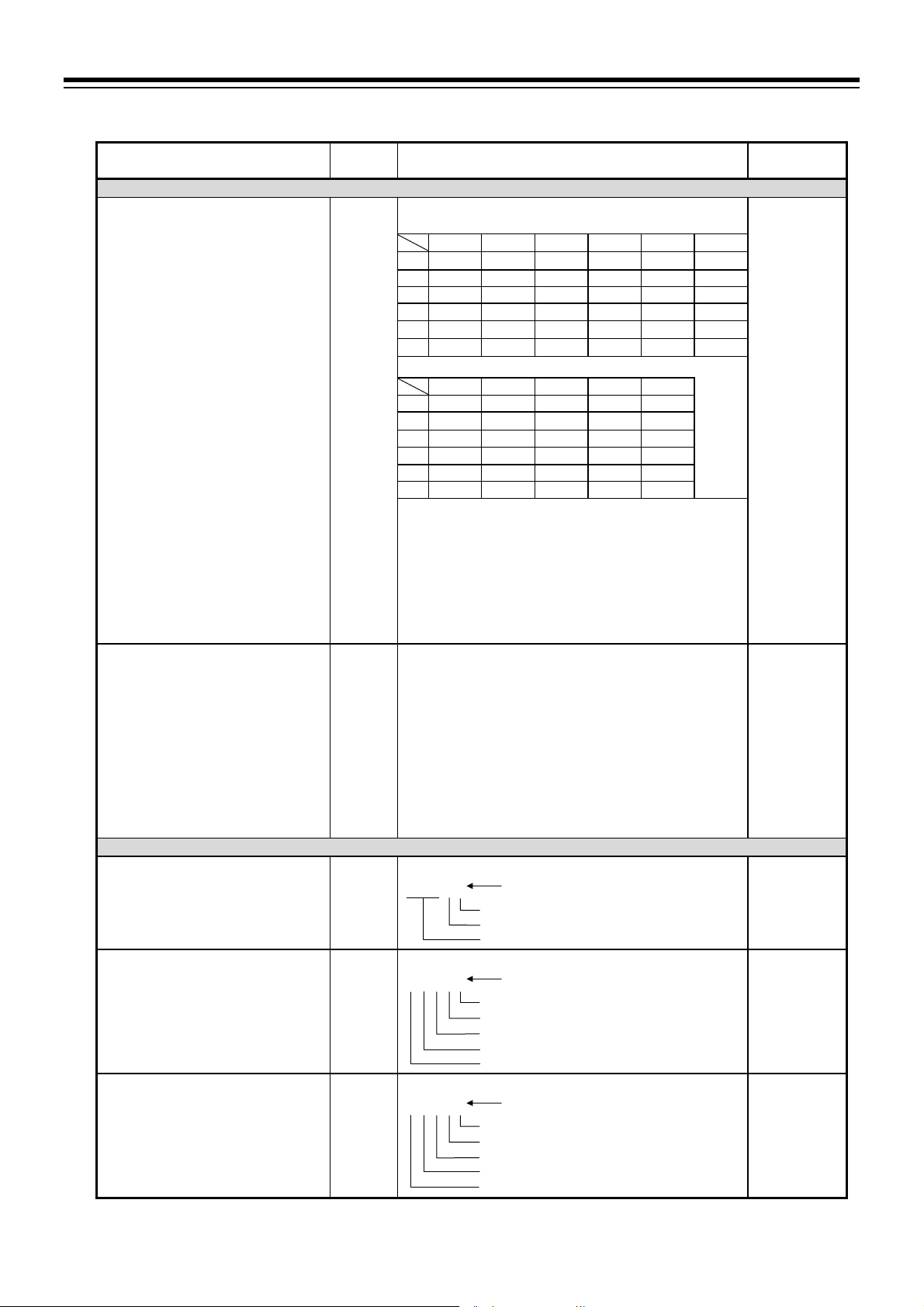
Continued from the previous page.
Name Symbol Data range
Digital input (DI) assignment
Pattern input method of Digital input
(DI)
OUT2, OUT3
Energized/De-energized
DO1 to DO4
Energized/De-energized
DO5 to DO8
Energized/De-energized
Function block 23 (F23.01, F23.02)
DISL
DIPTN
Function block 30 (F30.01 to F30.08)
EXOUT
EXDO1
EXDO2
0 to 5
DI1 to DI6 (Optional)
DI1 DI2 DI3 DI4 DI5 DI6
0 PTN1 PTN2 PTN4 PTN8 PTN16 P.SET
1 PTN1 PTN2 PTN4 PTN8 PTN16 P.SET
2 WAIT WAIT WAIT WAIT WAIT WAIT
3 WAIT WAIT WAIT WAIT WAIT WAIT
4 WAIT WAIT WAIT WAIT WAIT WAIT
5 WAIT WAIT WAIT WAIT WAIT WAIT
DI7 to DI11 (Standard)
DI7 DI8 DI9 DI10 DI11
0 RESET RUN STEP HOLD PTN32
1 RESET RUN STEP PTN32 PTN64
2 PTN1 PTN2 PTN4 PTN8 P.SET
3 PTN1 PTN2 PTN4 PTN8 PTN16
4 RESET RUN STEP HOLD D/R
5 RESET RUN STEP HOLD
PTN1 to PTN64: Pattern number switch
P.SET: Pattern set
WAIT: Wait state release
RESET: Reset mode setting
RUN: Program control mode setting
HOLD: Hold function
STEP: Step function
D/R: Direct/Reverse action switching
PTN_INC Pattern increment
0: Set Pattern number by using the Pattern set input.
Pattern number Binary number of DI 1
1: Set Pattern number by switching the contact input.
Pattern number Binary number of DI 1
2: Set Pattern number by using the Pattern set input.
Pattern number Binary number of DI
3: Set Pattern number by switching the contact input.
Pattern number Binary number of DI
To change Pattern number, refer to Pattern number
switch of the PF900/PF901 Instruction Manual
(IMR02L03-E) on the CD-ROM.
0: Energized 1: De-energized
00000 Value at SV display
OUT2
OUT3
Unused
0: Energized 1: De-energized
00000 Value at SV display
DO1
DO2
DO3
DO4
Unused
0: Energized 1: De-energized
00000 Value at SV display
DO5
DO6
DO7
DO8
Unused
4. BASIC OPERATION
Factory set
value
Based on
model code.
When not
specifying: 0
PTN_INC
0
00
0000
0000
Continued on the next page.
IMR02L04-E3
4-35
Page 84

4. BASIC OPERATION
t
Continued from the previous page.
Name Symbol Data range
DO9 to DO12
Energized/De-energized
Transmission output action in Reset
mode
Event action in Reset mode
Transmission output action at Pattern
end
Event action at Pattern end
OUT1 assignment
OUT2 assignment
EXDO3
R.AO
R.EV
P.ED.AO
P.ED.EV
LOGC1
Function block 32 (F32.01 to F32.03)
LOGC2
0: Energized 1: De-energized
00000 Value at SV display
DO9
DO10
DO11
DO12
Unused
0: Action stop 1: Action continued
00000 Value at SV display
OUT2
OUT3
Unused
0: Action stop 1: Action continued
00000 Value at SV display
Event 1
Event 2
Event 3
Event 4
0: Action stop 1: Action continued
00000 Value at SV display
OUT2
OUT3
Unused
Action of OUT1 stops or continues based on the setting of
Control action selection at Pattern end.
0: Action stop 1: Action continued
00000 Value at SV display
Event 1
Event 2
Event 3
Event 4
Function block 31 (F31.01)
0: Manipulated output value 1 (MV1) [For Control output]
[PID control or Heat/Cool PID control: Heat-side output
Position proportioning PID control: Open-side output]
1: Output program value 1 [For Control output or
Transmission output (Voltage/Current output)]
Voltage output or Current outpu
Control output: 1, 2, 7
Transmission output: 3 to 7
0: None
1: Manipulated output value 1 (MV1) [Feedback
resistance (FBR) input value when FBR input is
specified with the Position proportioning PID control.]
2: Manipulated output value 2 (MV2) [Cool-side output
at Heat/Cool PID control]
3: Measured value (PV)
4: Deviation value (DEV)
5: Set value (SV) monitor
6: Segment time (percentage basis)
7: Output program value 2
Manipulated output value (MV1 or MV2) may be used as a
transmission output.
Relay contact output, Voltage pulse output, Triac output
or Open collector output
Control output: 21, 22, 23
Event output: 24 to 53
20: None
HBA1 or HBA2
HBA1 or HBA2
Factory set
value
0000
00
00000
00
00000
0
Heat/Cool PID
control:
22 or 2
(varies with
output type)
Position
proportioning
PID control:
22
Other control
method:
0 or 20
(varies with
output type)
When the
OUT2 is not
provided: 0
Continued on the next page.
4-36
IMR02L04-E3
Page 85

Continued from the previous page.
Name Symbol Data range
OUT2 assignment
(A continuance)
OUT2 transmission output scale high
OUT2 transmission output scale low
OUT3 assignment
OUT3 transmission output scale high
LOGC2
AHS2
ALS2
Function block 33 (F33.01 to F33.03)
LOGC3
AHS3
21: Manipulated output value 1 (MV1)
PID control or Heat/Cool PID control: Heat-side output
[Feedback resistance (FBR) input value when FBR
input is specified with the Position proportioning PID
control.]
22: Manipulated output value 2 (MV2)
Heat/Cool PID control: Cool-side output
Position proportioning PID control: Close-side output
23: Output program value 2
24 to 31: Time signal 1 to Time signal 8
32 to 35: Event 1to Event 4
36: HBA1
37: HBA2
38: Logical OR of HBA1 and HBA2
39: LBA
40: Input error state
41: Program control mode (RUN) state
42: Fixed set point control mode (FIX) state
43: Manual control mode (MAN) state
44: Ramp state
45: Soak state
46: Hold state
47: Wait state
48: Pattern end signal
49: Autotuning (AT) state
50: FAIL state
51: Host communication error
52: Intercontroller communication error
53: Feedback resistance (FBR) input error
Varies with OUT2 assignment.
Measured value (PV), Set value (SV) monitor:
Input range low to Input range high
Deviation value (DEV):
Input span to Input span
(Within 19999 to 32000 [excluding decimal point])
Output program value 2:
Fixed at 100.0 % (scaling is not available)
Segment time (percentage basis):
Fixed at 100.0 % (scaling is not available)
When using Manipulated output value (MV1 or MV2) as a
transmission output: Fixed at 100.0 % (scaling is not available)
Varies with OUT2 assignment.
Measured value (PV), Set value (SV) monitor:
Input range low to Input range high
Deviation value (DEV):
Input span to Input span
(Within 19999 to 32000 [excluding decimal point])
Output program value 2:
Fixed at 0.0 % (scaling is not available)
Segment time (percentage basis):
Fixed at 0.0 % (scaling is not available)
When using Manipulated output value (MV1 or MV2) as a
transmission output:
The data range is same as OUT2 assignment.
However, No. 7 or 23 becomes output program value 3.
There are no relay contact output and triac output in OUT3
No control output when No. 21 or 22 is selected at Position
proportioning PID control.
Varies with OUT3 assignment.
The data range is the same as the OUT2 transmission output scale high.
Fixed at 0.0 % (scaling is not available)
4. BASIC OPERATION
Factory set
value
Heat/Cool PID
control:
22 or 2
(varies with
output type)
Position
proportioning
PID control:
22
Other control
method:
0 or 20
(varies with
output type)
When the
OUT2 is not
provided: 0
Measured
value (PV),
Set value (SV)
monitor:
Input range
high
Deviation
value (DEV):
Input span
Other: 100.0
Measured
value (PV),
Set value (SV)
monitor:
Input range
low
Deviation
value (DEV):
Input span
Other: 0.0
0 or 20
(varies with
output type)
When the
OUT3 is not
provided: 0
Continued on the next page.
IMR02L04-E3
4-37
Page 86

4. BASIC OPERATION
Continued from the previous page.
Name Symbol Data range
OUT3 transmission output scale low
DO1 assignment
DO2 assignment
DO3 assignment
DO4 assignment
DO5 assignment
DO6 assignment
DO7 assignment
DO8 assignment
DO9 assignment
DO10 assignment
DO11 assignment
DO12 assignment
Event 1 type
Event 1 hold action
Event 1 differential gap
Event 1 output action at input error
Event 1 timer
ALS3
Function block 34 (F34.01 to F34.12)
LDO1
LDO2
LDO3
LDO4
LDO5
LDO6
LDO7
LDO8
LDO9
LDO10
LDO11
LDO12
Function block 41 (F41.01 to F41.08)
ES1
EHO1
EH1
EBO1
EVT1
Varies with OUT3 assignment.
The data range is the same as the OUT2 transmission output scale low.
0: None
1 to 8: Time signal 1 to Time signal 8
9 to 12: Event 1 to Event 4
13: HBA1
14: HBA2
15: Logical OR of HBA1 and HBA2
16: LBA
17: Input error state
18: Program control mode (RUN) state
19: Fixed set point control mode (FIX) state
20: Manual control mode (MAN) state
21: Ramp state
22: Soak state
23: Hold state
24: Wait state
25: Pattern end signal
26: Autotuning (AT) state
27: FAIL state
28: Host communication error
29: Intercontroller communication error
30: Feedback resistance (FBR) input error
0: None
1: Deviation high
2: Deviation low
3: Deviation high/low
4: Deviation high/low (Individual high and low s etting)
5: Band
6: Band (Individual high and low setting)
7: Process high
8: Process low
9: SV high
10: SV low
11: MV1 high [heat-side]
12: MV1 low [heat-side]
13: MV2 high [cool-side]
14: MV2 low [cool-side]
1
Event hold action is available.
2
If there is F e e dback resist a nce (FBR) input in Position
proportioning PID control, set to the FBR input value.
0: OFF
1: Hold action ON
[when power turned on; when Event start (SV changed)]
Deviation, process or set value:
MV: 0.0 to 110.0 %
0 to 4 0
0 Conforms to Event action Conforms to Event action
1 ON Conforms to Event action
2 Conforms to Event action ON
3ON ON
4 OFF OFF
0.0 to 600.0 seconds 0.0
1
0 to Input span (Unit: C [F])
When PV reaches Input
error determination point
(high) or higher
temperature:
1
1
1
1
1
1, 2
1, 2
1
1
1
When PV reaches Input
error determination point
(low) or lower
temperature:
Continued on the next page.
Factory set
value
Based on
model code.
When not
specifying:
DO1: 9
DO2: 10
DO3: 1
DO4: 25
When
specifying 12
points of DO
at ordering:
DO5 to DO12:
1 to 8
When
specifying 4
points of DO
at ordering:
DO5 to DO12:
0
Based on
model code.
When not
1
specifying: 1
Based on
model code.
When not
specifying: 0
TC/RTD: 2
V/I: 0.2
MV: 0.2
4-38
IMR02L04-E3
Page 87

Continued from the previous page.
Name Symbol Data range
Event 1 interlock
Event 1 minimum ON time
Event 1 minimum OFF t ime
Event 2 type
Event 2 hold action
Event 2 differential gap
Event 2 output action at input error
Event 2 timer
Event 2 interlock
Event 2 minimum ON time
Event 2 minimum OFF t ime
Event 3 type
Event 3 hold action
Event 3 differential gap
Event 3 output action at input error
Event 3 timer
Event 3 interlock
Event 3 minimum ON time
Event 3 minimum OFF t ime
Event 4 type
Event 4 hold action
Event 4 differential gap
Event 4 output action at input error
Event 4 timer
Event 4 interlock
Event 4 minimum ON time
Event 4 minimum OFF t ime
EIL1
E1ON
E1OFF
Function block 42 (F42.01 to F42.08)
ES2
EHO2
EH2
0: Unused
1: Used
2: Activate Interlock and switch to the Manual control
mode to produce Manipulated output at Input error.
0.0 to 600.0 seconds 0.0
0.0 to 600.0 seconds 0.0
The data range is same as Event 1 type.
The data range is same as Event 1 hold action.
The data range is same as Event 1 differential gap.
EBO2
EVT2
EIL2
E2ON
E2OFF
Function block 43 (F43.01 to F43.08)
ES3
EHO3
EH3
The data range is same as Event 1 type.
The data range is same as Event 1 hold action.
The data range is same as Event 1 differential gap.
EBO3
EVT3
EIL3
E3ON
E3OFF
Function block 44 (F44.01 to F44.08)
ES4
EHO4
EH4
The data range is same as Event 1 type.
The data range is same as Event 1 hold action.
The data range is same as Event 1 differential gap.
EBO4
EVT4
EIL4
E4ON
E4OFF
4. BASIC OPERATION
Factory set
value
0
Based on
model code.
When not
specifying: 2
Based on
model code.
When not
specifying: 1
Based on
model code.
When not
specifying: 0
Based on
model code.
When not
specifying: 0
Based on
model code.
When not
specifying: 0
Based on
model code.
When not
specifying: 0
Continued on the next page.
IMR02L04-E3
4-39
Page 88

4. BASIC OPERATION
Continued from the previous page.
Name Symbol Data range
Function block 45 (F45.01 to F45.05)
CT1 ratio
CT1 assignment
Number of heater break alarm 1
(HBA1) delay times
Heater break alarm 1 (HBA1)
set value *
Heater break alarm 1 (HBA1)
interlock
CT2 ratio
CT2 assignment
Number of heater break alarm 2
(HBA2) delay times
Heater break alarm 2 (HBA2)
set value *
Heater break alarm 2 (HBA2)
interlock
Control loop break alarm (LBA)
selection
Control loop break alarm (LBA)
interlock
* It is not necessary to change the operation mode to the Reset mode (RESET) when setting the parameters. The parameters may
also be set in the Setup setting mode.
CTR1
CTA1
HBC1
HBA1
HBIL1
Function block 46 (F46.01 to F46.05)
CTR2
CTA2
HBC2
HBA2
HBIL2
Function block 47 (F47.01, F47.02)
LBASL
LBIL
0 to 9999 CTL-6-P-N:
0: None
1: OUT1
2: OUT2
3: OUT3
0 to 255 times 5
CTL-6-P-N:
0.0 to 30.0 A
CTL-12-S56-10L-N:
0.0 to 100.0 A
0.0: Unused (Current value monitoring still available.)
0: Unused
1: Used
2: Activate Interlock and switch to the Manual control
mode to produce Manipulated output at Input error.
The data range is same as Function block 45 (F45.) CTL-6-P-N:
0: Without LBA
1: With LBA
0: Unused
1: Used
2: Activate Interlock and switch to the Manual control
mode to produce Manipulated output at input error.
Continued on the next page.
Factory set
value
800
CTL-12-S56:
1000
When not
specifying: 800
When
specifying CT
at ordering: 1
When not
specifying: 0
0.0
0
800
CTL-12-S56:
1000
When not
specifying: 800
When
specifying CT
at ordering: 2
When not
specifying: 0
5
0.0
0
0
0
4-40
IMR02L04-E3
Page 89

4. BASIC OPERATION
Continued from the previous page.
Name Symbol Data range
Function block 50 (F50.01 to F50.14)
Control action
Hot/Cold start
Start determination point
Action (high) at input error
Action (low) at input error
Manipulated output value at input
error
Control action at Pattern end *
Intensity factor of Ramp/Soak
stabilizer
OUT1 proportional cycle time *
OUT1 minimum ON/OFF time of
proportioning cycle
OUT2 proportional cycle time *
OUT2 minimum ON/OFF time of
proportioning cycle
OUT3 proportional cycle time *
OUT3 minimum ON/OFF time of
proportioning cycle
AT bias
AT differential gap time
AT time signal action
* It is not necessary to change the operation mode to the Reset mode (RESET) when setting the parameters. The parameters may
also be set in the Setup setting mode.
OS
PD
PDA
AOVE
AUNE
PSM
END.P
RSS.AJ
T1
O1.TM
T2
O2.TM
T3
O3.TM
Function block 52 (F52.01 to F52.07)
ATB
ATHS
ATTS
0: Brilliant II PID control (direct action)
1: Brilliant II PID control (reverse action)
2: Brilliant II Heat/Cool PID control
3: Brilliant II Heat/Cool PID control (air cooling)
4: Brilliant II Heat/Cool PID control
(cooling gain linear type)
5: Brilliant II Position proportioning PID control
(reverse action)
6: Brilliant II Position proportioning PID control
(direct action)
0: Hot start 1 2: Cold start
1: Hot start 2 3: Reset start
0 to Input span (The unit is the same as input value.)
0: Normal control
1: Manipulated output value at input error
PID contorl:
Heat/Cool PID control: 105.0 to 105.0 %
Actual output values become those restricted by the Output
limiter.
PID control or Heat/Cool PID control,
Position proportioning PID control (with FBR input):
0: Control continued 1: Control stop
Control action at Pattern end can be operative when using
Output program function.
Position proportioning PID con t r ol (Whe n there i s no FBR
input or the FBR input is break):
0: Control continued
1: Open-side output OFF, Close-side output OFF
2: Open-side output OFF, Close-side output ON
3: Open-side output ON, Close-side output OFF
0.0 to 1.0
0.0: Unused
0.1 to 100.0 seconds
M: Relay contact output T: Triac output
V: Voltage pulse output D: Open collector output
0 to 1000 ms 0
0.1 to 100.0 seconds
M: Relay contact output T: Triac output
V: Voltage pulse output D: Open collector output
0 to 1000 ms 0
0.1 to 100.0 seconds
V: Voltage pulse output D: Open collector output
0 to 1000 ms 0
Input span to Input span
(The unit is the same as input value)
0.0 to 100.0 seconds 10.0
0: Time signal OFF
1: Time signal ON
5.0 to 105.0 %
(water cooling)
Continued on the next page.
Factory set
value
Based on
model code.
When
specifying
FBR input or
Z action
ordering: 5
When initial
setting is not
specifying: 1
0
3 % of Input span
0
0
0.0
0
0.5
M: 20.0
V/T/D: 2.0
M: 20.0
V/T/D: 2.0
When the
OUT2 is not
provided: 2.0
V/D: 2.0
When the
OUT3 is not
provided: 2.0
0
0
IMR02L04-E3
4-41
Page 90

4. BASIC OPERATION
t
t
t
Continued from the previous page.
Name Symbol Data range
AT cycles
Output value with AT turned on
Output value with AT turned off
AT with learning function at ramp
segment
Action at feedback resistance (FBR)
input error
Feedback adjustment
ATC
ATON
ATOF
ATT.R
Function block 53 (F53.01 to F53.05)
YBR
POS
0: 1.5 cycles 2: 2.5 cy cles
1: 2.0 cycles 3: 3.0 cycles
Output value with AT turned off to +105.0 %
Actual output values become those restricted by the Output
limiter.
Position proportioning PID control:
Becomes valid only when there is Feedback resistance
(FBR) input and it does not break (high limit of Feedback
resistance input at AT).
105.0 % to Output value with AT turned on
Actual output values become those restricted by the Output
limiter.
Position proportioning PID control:
Becomes valid only when there is Feedback resistance
(FBR) input and it does not break (low limit of Feedback
resistance input at AT).
0: No AT with learning function at ramp segment
1: Conduct AT with learning function at ramp segment
0: Action depending on the Valve action at Reset mode
1: Control action continued
ADJ: Adjustment end
OPEN: During adjustment on the open - side
CLOSE: During adjustment on the close-side
To start Feedback adjustment, press and hold the key
for 5 seconds or more at
ADJ display.
Err display: Adjustment error
When FBR input is not specified, only AdJ displays.
Control motor time
Integrated output limiter
Valve action in Reset mode
Communication 1 protocol
Device address 1 *
Communication speed 1 *
Data bit configuration 1 *
Interval time 1 *
* It is not necessary to change the operation mode to the Reset mode (RESET) when setting the parameters. The parameters may
also be set in the Setup setting mode.
MOT
OLA
VAL
Function block 60 (F60.01 to F60.05)
CMP1
ADD1
BPS1
BIT1
INT1
5 to 1000 seconds 10
0.0 to 200.0 % of Control motor time
0.0: OFF
Invalidate when Feedback resistance (FBR) input is selected.
0: Open-side output OFF, Close-side output OFF
1: Open-side output OFF, Close-side output ON
2: Open-side output ON, Close-si de output OFF
Invalidate when Feedback resistance (FBR) input is selected.
0: RKC communication
1: Modbus
RKC communication: 0 to 99
Modbus: 1 to 99
2400: 2400 bps 19200:19200 bps
4800: 4800 bps 38400: 38400 bps
9600: 9600 bps 57600: 57600 bps
Symbol Data bit Parity bi
8N1 a
a
8N2
8E1 a
8E2 a
8o1
8o2
7N1
7N2
7E1
7E2
7o1
7o2
a
Available for only Modbus
0 to 250 ms 10
8 bit
8 bit
8 bit
8 bit
8 bit
8 bit
7 bit
7 bit
7 bit
7 bit
7 bit
7 bi
Without
Without
Even
Even
Odd
Odd
Without
Without
Even
Even
Odd
Odd
Stop bit
1 bit
2 bit
1 bit
2 bit
1 bit
2 bit
1 bit
2 bit
1 bit
2 bit
1 bit
2 bi
Continued on the next page.
Factory set
value
0
105.0
105.0
0
0
ADJ
150.0
0
Based on
model code.
RKC
communication
0
Modbus: 1
19200
8N1
:
4-42
IMR02L04-E3
Page 91

4. BASIC OPERATION
r
d
Continued from the previous page.
Name Symbol Data range
Function block 61 (F61.01 to F61.06)
Slave controller
Number of slave unit
Device address 2 *
Communication speed 2 *
Host communication error judgment
time
Intercontroller communication error
judgment time
Setting limiter high
Setting limiter low
SV selection at Program start *
Wait memory group number at
Program start
Program setting type
Signal type
Set time unit
Maximum pattern/segment number
* It is not necessary to change the operation mode to the Reset mode (RESET) when setting the parameters. The parameters may
also be set in the Setup setting mode.
SLV.SL
SLV.NO
ADD2
BPS2
H.ER.TM
C.ER.TM
Function block 71 (F71.01, F71.02)
SLH
SLL
Function block 80 (F80.01 to F80.07)
ST.SV
ST.WT
PR.TYP
TS.TYP
TM.SL
PNŠSN
0: FB series: FB100/400/900
1: RB series: RB100/400/500/700/900
2: PF900/901
0 to 4 0
0 to 99 0
9600: 9600 bps
19200: 19200 bps
38400: 38400 bps
0 to 600 seconds
0: Unused
0 to 600 seconds
0: Real-time error
Setting limiter low to Input range high
(The unit is the same as input value)
Input range low to Setting limiter high
(The unit is the same as input value)
0: Start with the Set value (SV) in the Reset mode.
1: PV start 1 [Time fixed type]
2: PV start 2 [Time saving & ramp holding type]
3: PV start 3 [Time saving & level searching type/
With HOLD function at start]
4: PV start 4 [Time saving & level searching type/
Without HOLD function at start]
0: Wait OFF
1 to 8: Wait memory 1 to Wait memory 8
0: Batch setting type
1: Partial setting type
0: Time signal type
1: Segment signal type
0: Hou
: Minute
1: Minute
Maximum pattern number: 1 to 99
Maximum segment number: 1 to 99
Maximum pattern number Maximum segment number
1024 at maximum
: Secon
Factory set
value
0
19200
10
10
Input range
high
Input range
low
2
0
1
0
0
Maximum
pattern
number: 32
Maximum
segment
number: 32
IMR02L04-E3
4-43
Page 92

4. BASIC OPERATION
Parameter switching
To go to the Parameter setting mode, press the
PV/SV monitor dis play.
Press the
Function blocks may be switched by using the
PV/SV monitor
PV
00028
M:S
5 30:00000200
Function block 10
PV
M:S
FIX000RDISP
PV
M:S
FIX000RDKEY
(F10.)
F10.
Function block 11
(F11.)
F11.
Function block 21
(F21.)
key to switch operation screen.
Parameters in the Engineering mode are only available for monitoring in the RUN mode, the
FIX mode and the MAN mode. Switch to the RESET mode to set the parameters. It is
possible to set parameters in the function block 10 (F10) and the function block 11 (F11) in
the RUN mode, the FIX mode and the MAN mode.
Press the key to go back to the PV/SV monitor.
Press the STEP R.SET key to go back to the previous display.
Press the STEP R.SET key while pressing the
function block.
Display returns to the PV/SV monitor if no key operation is performed within 1 minute.
$
SV
SV
Press the
Parameter setting
mode
key while pressing the key for 2 seconds or more.
PV flashing display
at input error
PV
0 DSOP
M:S
SV
F10.01R 00000
(P. 4-32)
Power saving mode
duration
PV
OFFTM
M:S
SV
F10.11R 00000
RESET key type
PV
KTYP1
M:S
SV
SV
F11.01R 00001
(P. 4-33)
STEP key type
PV
KTYP6
M:S
SV
F11.06R 00003
key while pressing the
key or the key.
key to go back to the first setting display of the
Setup setting
mode
Setting parameters from F10.02 to F10.10
F10.02: Dot monitor type
F10.03: Dot monitor scale high
F10.04: Dot monitor scale low
F10.05: ALM lamp light condition
F10.06: ALM lamp light condition
F10.07: ALM lamp light condition
F10.08: Dot monitor at ALM lamp light
F10.09: TS lamp light condition 1
F10.10: TS lamp light condition
Setting parameters from F11.02 to F11.05
F11.02: RUN key type
F11.03: FIX key type
F11.04: MAN key type
F11.05: HOLD key type
key for 2 seconds or more at
1
2
3
2
4-44
IMR02L04-E3
Page 93
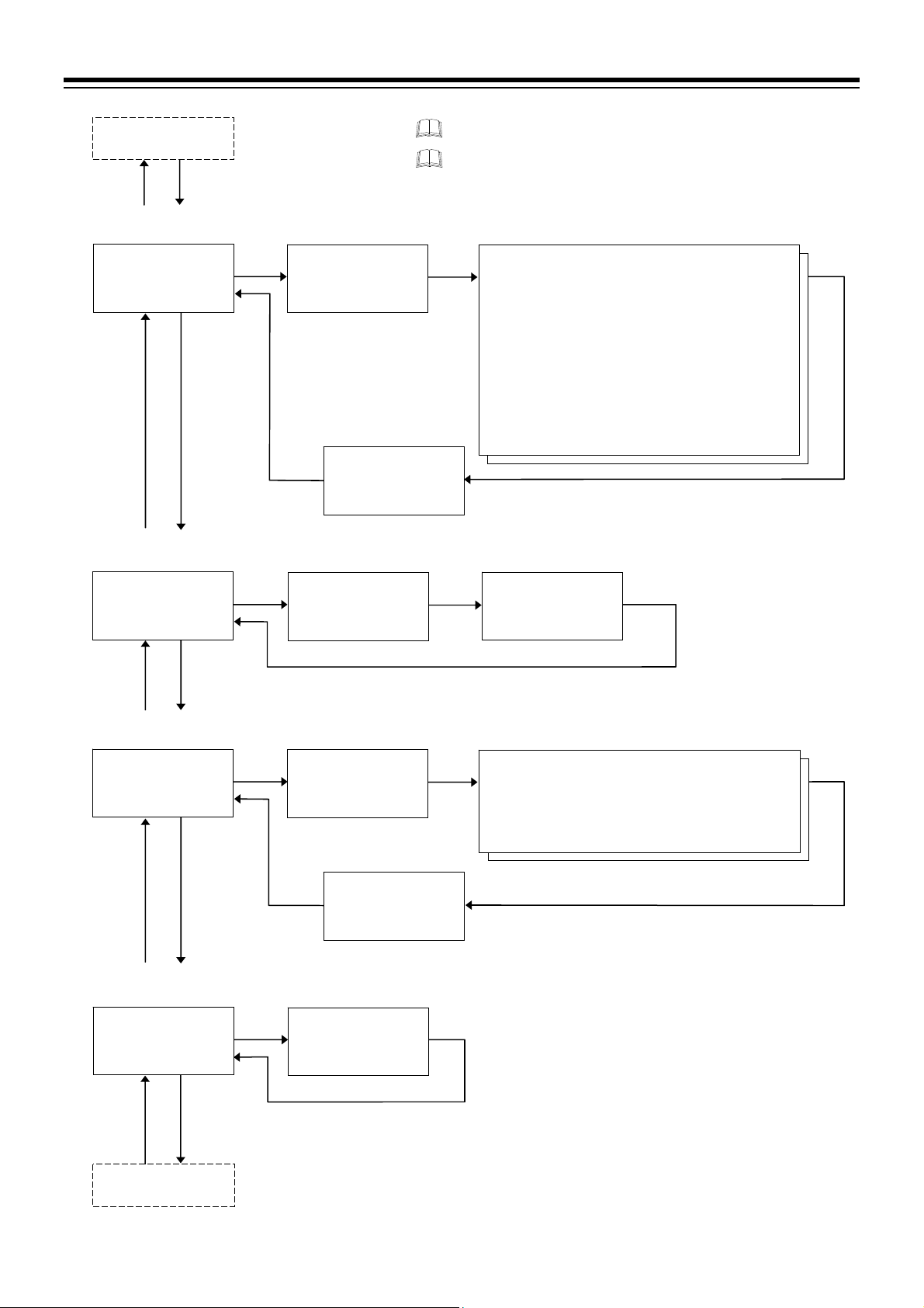
Function block 11
PV
M:S
FIX000RDINP
PV
M:S
FIX000RDKDI
PV
M:S
FIX000RDOUT
PV
M:S
FIX000ROUT1
(F11.)
Function block 21
(F21.)
F21.
SV
Function block 23
(F23.)
F23.
SV
Function block 30
(F30.)
F30.
SV
Function block 31
(F31.)
F31.
SV
Function block 32
(F32.)
(P. 4-33)
(P. 4-35)
(P. 4-35)
(P. 4-36)
Input type
PV
KTINP
M:S
F21.01R 00001
PV low input cut-off
PV
M:S
F21.15R 000.00
Digital input (DI)
assignment
PV
K DISL
M:S
F23.01R 00000
OUT2, OUT3
Energized/De-energized
PV
EXOUT
M:S
F30.01R 00000
PV
M:S
F30.08R 00000
OUT1 assignment
PV
LOGC1
M:S
F31.01R 00000
SV
L-CUT
SV
SV
SV
Event action
at Pattern end
P.E D.E V
SV
SV
4. BASIC OPERATION
Press the STEP R.SET key to go back to the previous display.
Press the STEP R.SET key while pressing the
back to the first setting display of the function block.
Setting parameters from F21.02 to F21.14
F21.02: Display unit
F21.03: Decimal point position
F21.04: Input range high
F21.05: Input range low
F21.06: Input error determination point (high)
F21.07: Input error determination point (low)
F21.08: Burnout direction
F21.09: Square root extraction
F21.10: Power supply frequency
F21.11: Sampling cycle
F21.12: PV bias
F21.13: PV digital filter
F21.14: PV ratio
key to go
Pattern input method
of Digital input (DI)
PV
DIPTN
M:S
SV
F23.02R 00000
Setting parameters from F30.02 to F30.07
F30.02: DO1 to DO4 Energized/De-energized
F30.03: DO5 to DO8 Energized/De-energized
F30.04: DO9 to DO12 Energized/De-energized
F30.05:
F30.06: Event action in Reset mode
F30.07:
Transmission output action in Reset mode
Transmission output action at Pattern end
IMR02L04-E3
4-45
Page 94

4. BASIC OPERATION
Function block 31
PV
M:S
FIX000ROUT2
PV
M:S
FIX000ROUT3
PV
M:S
FIX000RDIDO
PV
TM
FIX000RDEV1
(F31.)
SV
SV
(F34.)
SV
SV
(F45.)
(P. 4-36)
(P. 4-37)
(P. 4-38)
(P. 4-38)
(P. 4-39)
Function block 32
(F32.)
F32.
Function block 33
(F33.)
F33.
Function block 34
F34.
Function block 41
(F41.)
F41.
Function block 42
(F42.) to 44 (F44.)
Function block 45
OUT2 assignment
PV
LOGC2
M:S
SV
F32.01R 00000
OUT3 assignment
PV
LOGC3
M:S
SV
F33.01R 00000
DO1 assignment
PV
LDO1
M:S
SV
F34.01R 00000
DO12 assignment
PV
LDO12
M:S
SV
F34.12R 00000
Event 1 type
PV
KTES1
M:S
SV
F41.01R 00000
Event 1
minimum OFF time
PV
E1OFF
M:S
SV
F41.08R 0000.0
Press the STEP R.SET key to go back to the previous display.
Press the STEP R.SET key while pressing the
back to the first setting display of the function block.
OUT2 transmission
output scale high
PV
L AHS2
M:S
SV
%
F32.02R 0100.0
OUT3 transmission
output scale high
PV
L AHS3
M:S
SV
F33.02R 0100.0
Setting parameters from F34.02 to F34.11
F34.02: DO2 assignment
F34.03: DO3 assignment
F34.04: DO4 assignment
F34.05: DO5 assignment
F34.06: DO6 assignment
F34.07: DO7 assignment
F34.08: DO8 assignment
F34.09: DO9 assignment
F34.10: DO10 assignment
F34.11: DO11 assignment
Setting parameters from F41.02 to F41.07
F41.02: Event 1 hold action
F41.03: Event 1
F41.04: Event 1 output action at input error
F41.05: Event 1 timer
F41.06: Event 1 interlock
F41.07: Event 1 minimum ON time
differential gap
Event 2 to Event 4
(The setting parameter is same as Event 1.)
key to go
OUT2 transmission
output scale low
PV
L ALS2
M:S
SV
F32.03R 0000.0
OUT3 transmission
output scale low
PV
L ALS3
M:S
SV
F33.03R 0000.0
%
4-46
IMR02L04-E3
Page 95
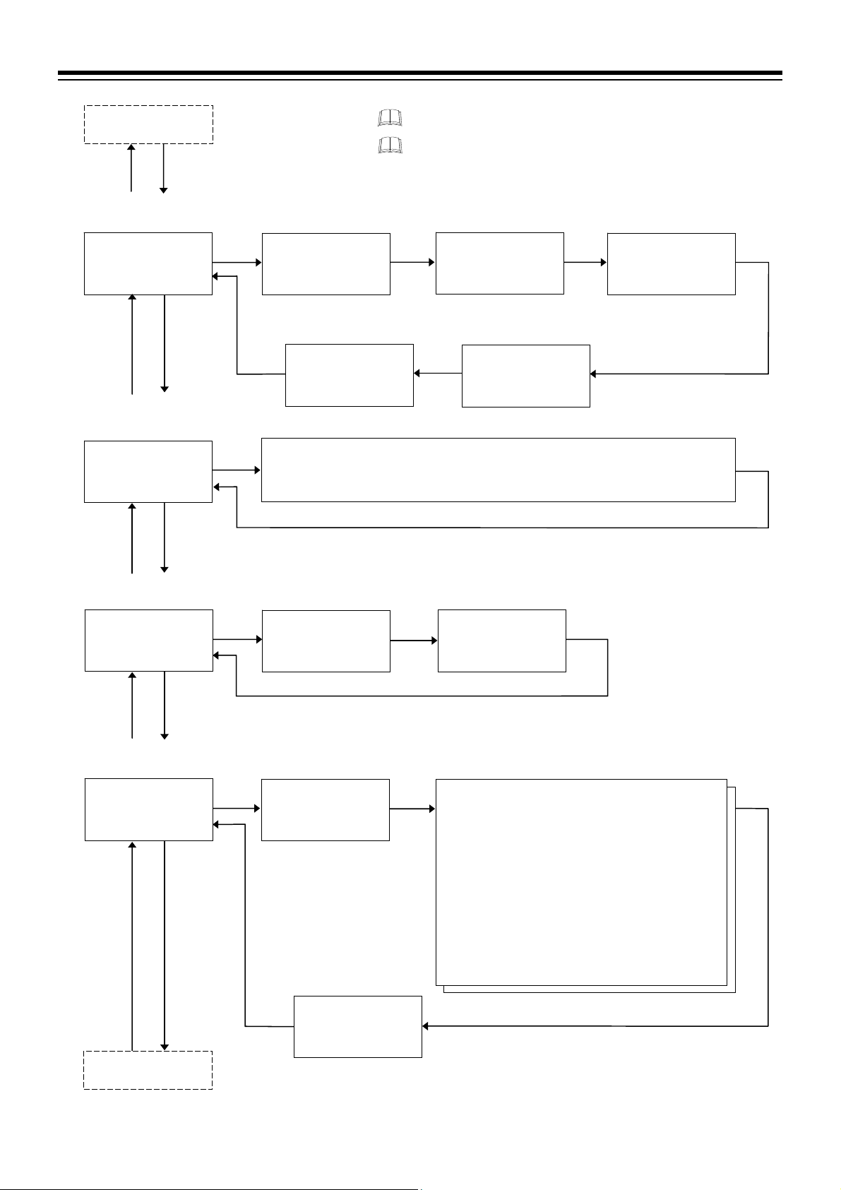
Function block 44
PV
M:S
FIX000RHBA1
PV
M:S
FIX000RHBA2
PV
M:S
FIX000ROLBA
PV
M:S
FIX000CONTR
(F44.)
Function block 45
(F45.)
F45.
SV
Function block 46
(F46.)
F46.
SV
Function block 47
(F47.)
F47.
SV
Function block 50
(F50.)
F50.
SV
Function block 52
(F52.)
(P. 4-40)
(P. 4-40)
(P. 4-40)
(P. 4-41)
CT1 ratio
PV
L CTR1
M:S
SV
F45.01R 00800
Heater break alarm 1
(HBA1) interlock
PV
HBIL1
M:S
F45.05R 00000
Control loop break
alarm (LBA) selection
PV
LBASL
M:S
SV
F47.01R 00000
Control action
PV
KTIOS
M:S
SV
F50.01R 00001
OUT3 minimum ON/OFF
time o f proportioning cycle
PV
L O3.TM
M:S
F50.14R 00000
Press the STEP R.SET key to go back to the previous display.
Press the STEP R.SET key while pressing the
back to the first setting display of the function block.
CT1 assignment
PV
L CTA1
M:S
SV
F45.02R 00001
Heater break alarm 1
(HBA1) set value
PV
L HBA1
M:S
SV
SV
F45.04R 0000.0
HBA2
(The setting parameter is same as HBA1.)
Control loop break
alarm (LBA) interlock
PV
L LBIL
M:S
SV
F47.02R 00000
Setting parameters from F50.02 to F50.13
F50.02: Hot/Cold start
F50.03: Start determination point
F50.04: Action (high) at input error
F50.05: Action (low) at input error
F50.06: Manipulated output value at input error
F50.07: Control action at Pattern end
F50.08: Intensity factor of Ramp/Soak stabilizer
F50.09: OUT1 proportional cycle time
F50.10: OUT1
proportioning cycle
F50.11: OUT2 proportional cycle time
F50.12: OUT2 minimu m O N /OFF ti m e of
proportioning cycle
F50.13: OUT3 proportional cycle time
minimum ON/OFF time of
SV
4. BASIC OPERATION
Number of heater
break alarm 1 (HBA1)
delay times
PV
L HBC1
M:S
F45.03R 00005
SV
key to go
IMR02L04-E3
4-47
Page 96

4. BASIC OPERATION
r
Function block 50
PV
M:S
FIX000RDIAT
PV
M:S
FIX000VALVE
PV
M:S
FIX000VSCI.1
PV
M:S
FIX000VSCI.2
(F50.)
(F52.)
SV
(F53.)
SV
(F60.)
SV
(F61.)
SV
(F71.)
(P. 4-41)
(P. 4-42)
(P. 4-42)
(P. 4-43)
Function block 52
F52.
Function block 53
F53.
Function block 60
F60.
Function block 61
F61.
Function block 71
AT bias
PV
KTATB
M:S
SV
F52.01R 00000
AT with learning function
at ramp segment
PV
L ATT.R
M:S
SV
F52.07R 00000
Action at feedback
resistance (FBR) input error
PV
LCYBR
M:S
SV
F53.01R 00000
Valve action
in Reset mode
PV
LHVAL
M:S
SV
F53.05R 00000
Communication 1
protocol
PV
L CMP1
M:S
SV
F60.01R 00000
Interval time 1
PV
L INT1
M:S
SV
F60.05R 00010
Slave controlle
PV
SLV.SL
M:S
SV
F61.01R 00000
Intercontroller communication
error judgment time
PV
C.E R.T M
M:S
SV
F61.06R 00010
Press the STEP R.SET key to go back to the previous display.
Press the STEP R.SET key while pressing the
back to the first setting display of the function block.
Setting parameters from F52.02 to F52.06
$
F52.02: AT differential gap time
F52.03: AT Time signal action
F52.04: AT cycles
F52.05: Output value with AT turned on
F52.06: Output value with AT turned off
Feedback adjustment
PV
LCPOS
M:S
SV
F53.02R00ADJ
Integrated output
limiter
PV
LCOLA
M:S
SV
%
Control motor time
PV
LCMOT
M:S
SV
F53.03R 00010
key to go
F53.04R 0150.0
Device address 1
PV
L ADD1
M:S
SV
F60.02R 00000
Data bit configuration 1
PV
L BIT1
M:S
SV
Communication speed 1
PV
L BPS1
M:S
SV
F60.03R 19200
F60.04R198N1
Number of slave unit
PV
SLV.NO
M:S
SV
F61.02R 00000
Host communication
error judgment time
PV
H.E R.T M
M:S
SV
F61.05R 00010
Device address 2
PV
L ADD2
M:S
SV
F61.03R 00000
Communication speed 2
PV
L BPS2
M:S
SV
F61.04R 19200
4-48
IMR02L04-E3
Page 97

w
Function block 61
(F61.)
Function block 71
PV
M:S
FIX000SCALE
(F71.)
F71.
SV
Function block 80
PV
M:S
FIX000VPROG
(F80.)
F80.
SV
First Function block
10 (F10.)
(P. 4-43)
(P. 4-43)
4. BASIC OPERATION
Press the STEP R.SET key to go back to the previous display.
Setting limiter high
PV
S0SLH
M:S
SV
F71.01R 01372
SV selection at
Program start
PV
S ST.SV
M:S
SV
F80.01R 00002
Maximum segment
number
PV
PNŠSN
M:S
SV
F80.07R 32Š32
Press the STEP R.SET key while pressing the
back to the first setting display of the function block.
Setting limiter lo
PV
$
LBSLL
M:S
SV
$
F71.02R -0200
Setting parameters from F80.02 to F80.05
F80.02: Wait memory group number at Program
start
F80.03: Program setting type
F80.04: Signal type
F80.05: Set time unit
Maximum pattern
number
PV
PNŠSN
M:S
SV
F80.06R 32Š32
Set maximum number
of segment
Set maximum number
of pattern
When changing a Maximum pattern number or Maximum segment
number, all parameters related to Program setting such as Segment level
and Segment time will be initialized automatically.
Parameters to be initialized
Parameter setting mode:
Parameters at the Program setting block
Wait zone high and Wait zone low at the Wait memory group setting block
Output program value from 1 to 3 at the Output program memory group setting block
Parameters at the Time signal memory group setting block
SV setting mode:
Execution pattern selection
Setting by RKC communication:
Pattern tag name
It takes approximately 1 second to initialize the related parameters when a
Maximum pattern number of Maximum segment number is changed.
key to go
IMR02L04-E3
4-49
Page 98

MEMO
4-50 IMR02L04-E3
Page 99
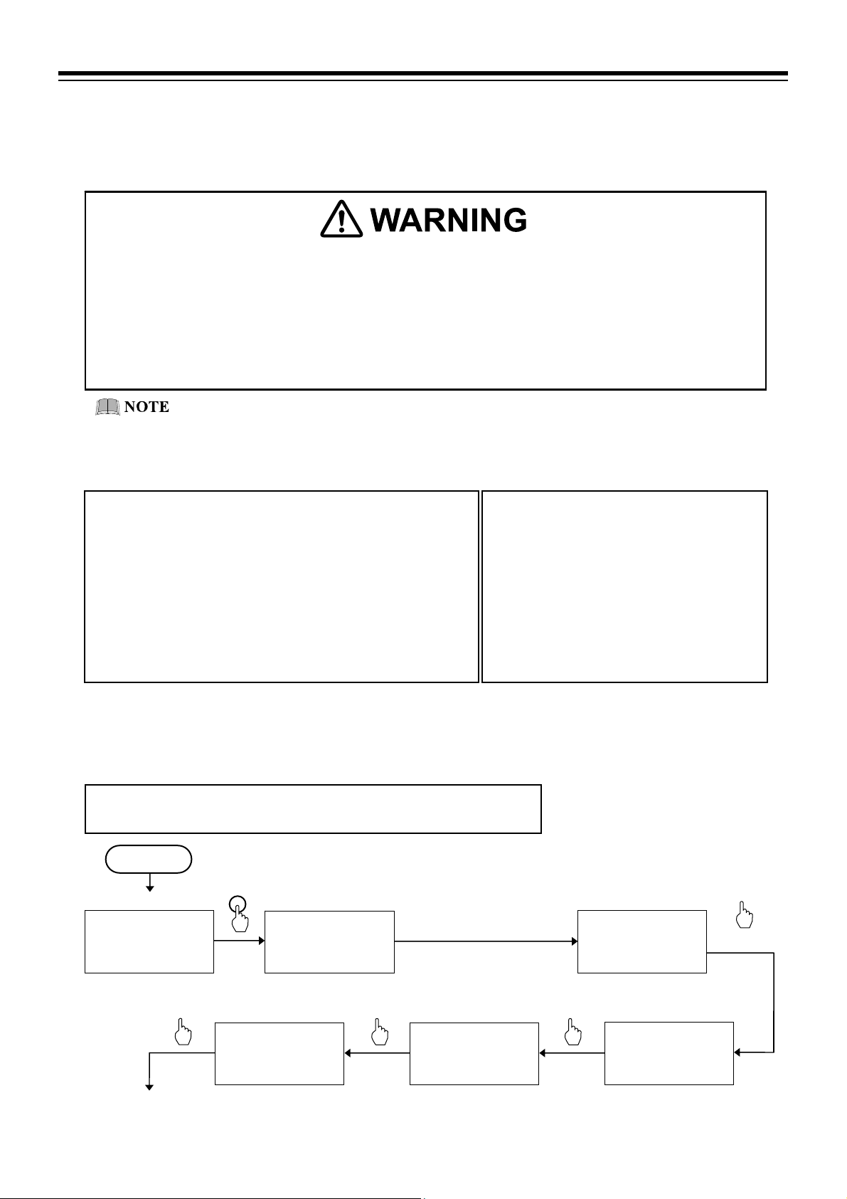
g
)
5. OPERATION
5.1 Initial Setting
Before starting operation, confirm that the set value of the parameter matches the model code as specified
when ordered. Parameters which are not specified when ordering must be set before use.
Parameters in the Engineering mode (F10 to F80) should be set according to the
application before setting any parameter related to operation. Once the parameters in
the Engineering mode are set correctly, no further changes need to be made to
parameters for the same application under normal conditions. If they are changed
unnecessarily, it may result in malfunction or failure of the instrument. RKC will not
bear any responsibility for malfunction or failure as a result of improper changes in
the Engineering mode.
Parameters in Engineering mode are settable only when the controller is in Reset mode
Setup the controller prior to operating the instrument. Refer to the following setup example.
Setup example:
Input specification: Thermocouple K 0 to 400 C
Control action: PID control (reverse action)
Control output: OUT1, Relay contact output,
Proportional cycle time: 20 seconds
Event specification (Event 1):
Deviation high/low with hold action
(Uses Interlock function)
Event output: Assigned to DO1
Program pattern/segment number:
Pattern/se
5.1.1 Check the parameter related to the input
(RESET).
ment number: 32/32 (Factory set value
Set value change and registration
The blinking digit indicates which digit can be
set.
The blinking digit can be moved by pressing
the
However, the changed data is not stored by the
operation of the
order for the new parameter value to be stored,
the
after the new value is displayed. The new value
will then be saved and the display will move to
key.
and keys alone. In
key must be pressed within 1 minute
the next parameter.
Check the set value of the parameter for input specification (such as the input type at F21 in the Engineering
mode). Parameters which are not specified when ordering must be set before use.
Setup example:
Input specification: Thermocouple (K) 0 to 400 °C [Input range code: K02]
Power ON
PV/SV monitor
PV
00028
M:S
SV
5 30:00000200
$
RESET
PV/SV monitor
(RESET mode)
PV
00028
M:S
SV
$
530:00000200
Press the key while
pressing the
2 seconds or more.
Continue to the next
parameter
IMR02L04-E3 5-1
Display unit
PV
K UNIT
M:S
SV
F21.02R 00000
Check Display unit.
00000: C
Input type
PV
KTINP
M:S
SV
F21.01R 00000
Check Input type.
00000: Thermocouple (K) –200 to +1372 C
key for
Function block 10
(F10.)
PV
F10.
M:S
SV
FIX000RDISP
Function block 21
PV
F21.
M:S
FIX000RDINP
(P. 4-32)
(F21.)
SV
Press twice.
(P. 4-33)
Page 100

5. OPERATION
Continued from the
previous parameter
PV
M:S
F21.08- 00000
Select Burnout direction.
00000: Upscale (Factory set value)
00001: Downscale
Square root extraction
PV
M:S
F21.09- 00000
Select Square root extraction.
00000: Unused (Factory set value)
00001: Used
Check the set value of the Setting limiter at the Function block 71 (F71.).
PV
M:S
FIX000SCALE
Decimal point position
PV
K PGDP
M:S
F21.03R 00000
Check Decimal point position.
0000: No decimal place
Burnout direction
KPBOS
SV
KPSQR
SV
Function block 71
(F71.)
F71.
(P. 4-43, P. 4-49)
SV
Input scale high
PV
M:S
SV
F21.04R 00400
Check Input scale high.
00400: 400 C
Input error determination
point (low)
PV
KPPUN
M:S
F21.07 -0020
Check Input error determination
point (low).
0020: 20 C
Power supply frequency
PV
K PFRQ
M:S
F21.10 0 00000
Select Power supply frequency.
00000: 50 Hz (Factory set value)
00001: 60 Hz
Return to
Function block 21
(F21.)
Setting limiterhigh
PV
S0SLH
M:S
SV
F71.01R 00400
Check Setting limiter high.
00400: 400 C
[Range: Setting limiter low to
Input range high]
K PGSH
SV
SV
SV
$
$
PV
M:S
F71.02R 00000
Check Setting limiter low.
00000: 0 C
[Range: Input range low to
$
Input scale low
PV
K PGSL
M:S
SV
F21.05R 00000
Check Input scale low.
00000: 0 C
Input error determination
point (high)
PV
KPPOV
M:S
SV
F21.06R 00420
Check Input error determination
point (high).
00420: 420 C
Sampling cycle
PV
KPSMP
M:S
SV
F21.11 - 00001
Select Sampling cycle.
00000: 50 ms
00001: 100 ms (Factory set value)
00002: 250 ms
F21.12: PV bias
F21.13: PV digital filter
F21.14: PV ratio
F21.15: PV low input cut-off
The parameters above may be set in the
Setup setting mode.
Setting limiterlow
LBSLL
SV
Setting limiter high]
$
$
$
5-2
IMR02L04-E3
 Loading...