

Page 1

A
Resin Pressure Measuring System
Instruction Manual
CZ-100P (Resin Pressure Sensor)
PCT-300 (Output Converter)
IM100CZ04-E2
Thank you for purchasing this RKC product. In order to achieve
maximum performance and ensure proper operation of your new
instrument, carefully read all the instructions in this manual. Please
place this manual in a convenient location for easy reference.
CONTENTS
1. OUTLINE ······································································ 2
2. PRODUCT CHECK······················································· 2
3. HANDLING OF THE PRESSURE SENSOR ················ 2
4. WIRING ········································································ 4
5. ADJUSTMENT······························································ 5
6. LINEARIZING FUNCTION SETTING ··························· 6
7. TROUBLES AND CAUSE············································· 6
8. EXPLANATION OF EACH TERMS ······························ 7
9. SPECIFICATIONS························································ 7
SYMBOLS
WARNING
CAUTION
An external protection device must be installed if failure
of this instrument could result in damage to the
instrument, equipment or injury to personnel.
All wiring must be completed before power is turned on
to prevent electric shock, fire or damage to instrument
and equipment.
This instrument must be used in accordance with the
specifications to prevent fire or damage to instrument
and equipment.
This instrument is not intended for use in locations
subject to flammable or explosive gases.
Do not touch high-voltage connections such as power
supply terminals, etc. to avoid electric shock.
RKC is not responsible if this instrument is repaired,
modified or disassembled by other than
factory-approved personnel. Malfunction can occur and
warranty is void under these conditions.
: This mark indicates precautions that must be taken
if there is danger of electric shock, fire, etc., which
could result in loss of life or injury.
: This mark indicates that if these precautions and
operating procedures are not taken, damage to the
instrument may result.
: This mark indicates that all precautions should be
!
taken for safe usage.
: This mark indicates important information on
installation, handling and operating procedures.
: This mark indicates supplemental information on
installation, handling and operating procedures.
: This mark indicates where additional information
may be located.
!
This is a Class A instrument. In a domestic environment, this
instrument may cause radio interference, in which case the user
may be required to take adequate measures.
This instrument is protected from electric shock by reinforced
insulation. Provide reinforced insulation between the wire for the
input signal and the wires for instrument power supply, source of
power and loads.
Be sure to provide an appropriate surge control circuit respectively
for the following:
- If input/output or signal lines within the building are longer than
30 meters.
- If input/output or signal lines leave the building, regardless the
length.
This instrument is designed for installation in an enclosed
instrumentation panel. All high-voltage connections such as power
supply terminals must be enclosed in the instrumentation panel to
avoid electric shock by operating personnel.
All precautions described in this manual should be taken to avoid
damage to the instrument or equipment.
All wiring must be in accordance with local codes and regulations.
To prevent instrument damage of failure, protect the power line
and the input/output lines from high currents with a protection
device such as fuse, circuit breaker, etc.
For an instrument with 24 V power supply, supply power from a
SELV circuit.
Prevent metal fragments or lead wire scraps from falling inside
instrument case to avoid electric shock, fire or malfunction.
Tighten each terminal screw to the specified torque found in the
manual to avoid electric shock, fire or malfunction.
Do not connect wires to unused terminals as this will interfere with
proper operation of the instrument.
Turn off the power supply before cleaning the instrument.
The resin adhered to this instrument should be cleaned to dry
cloth with a clean while the resin is still hardened, be careful of
burns.
Tools such as wire wheels or abrasive cloths should never be
used to clean the process diaphragm.
Do not apply impact to nor drop this product. If so, its damage or
fault may result.
As precise parts are incorporated, do not give any shock and
handle carefully during transportation and installation. Take great
care not to scratch the diaphragm.
Do not wipe or rub the nameplate on the outer case of the resin
pressure sensor with a cloth moistened with an organic solvent, or
a glove. If so, the printed section may be erased.
This product uses stainless steel, aluminum, and fluororesin (O-rings
and leadwire covering materials). When disposing of each part used
for this product, always follows the procedure for disposing of
industrial wastes stipulated by the respective local community.
CAUTION
NOTICE
This manual assumes that the reader has a fundamental
knowledge of the principles of electricity, process control,
computer technology and communications.
The figures, diagrams and numeric values used in this manual are
only for purpose of illustration.
RKC is not responsible for any damage or injury that is caused as
a result of using this instrument, instrument failure or indirect
damage.
Periodic maintenance is required for safe and proper operation of
this instrument. Some components have a limited service life, or
characteristics that change over time.
Every effort has been made to ensure accuracy of all information
contained herein. RKC makes no warranty expressed or implied,
with respect to the accuracy of the information. The information in
this manual is subject to change without prior notice.
No portion of this document may be reprinted, modified, copied,
transmitted, digitized, stored, processed or retrieved through any
mechanical, electronic, optical or other means without prior written
approval from RKC.
ll Rights Reserved, Copyright 1995, RKC INSTRUMENT INC.
RKC INSTRUMENT INC.
®
Page 2
A
1. OUTLINE
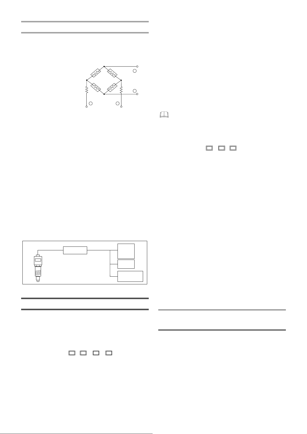
1.1 Principle of Operation
When pressure is applied to a diaphragm in the resin pressure
sensor (CZ-100P), force acts upon a pressure sensing element
through a metal rod located near the diaphragm.
The pressure sensing element
used in CZ-100P has 4 gauges
adhered to a metallic elastic
body and connected to
Wheatstone bridge. Each strain
gauge made of metal
resistance foil with small
temperature coefficient slightly
changes its gauge resistance
due to strain occurring by the
application of force to the
elastic body. In this case,
as shown in the attached diagram (Fig. 1), the elastic body is in such
construction that by the application of force stretching strain occurs
in R1 and R3, while shrinking strain in R2 and R4 to increase the
gauge resistances of R1 and R3 and to decrease those of R2 and
R4. These resistance changes are detected as bridge voltage
change to generate the output proportional to the force applied. The
output thus generated is input to the PCT-300 output converter
which can finally output the DC voltages of 0 to 10 V, 0 to 10 mV, 1
to 5 V and 4 to 20 mA from its output terminals via a 3-stage
amplifier circuit.
1.2 Features
• The detection of strain caused by the deformation of an elastic
metal body within its elasticity limit using the highly reliable strain
gauge enables highly accurate pressure measurement.
• The dual construction of connecting pipe and pressure sensing
element portions extremely lessens output indication change
caused by external transient temperature change.
• Calibration normally performed to a strain gauge sensor becomes
easy and accurate without monitoring the output due to the
employment of the PCT-300 output converter.
4-core shielded cable
Fig. 2 Block diagram of resin pressure system
Output converter
PCT-300
CZ-100P
Pressure sensor
R4
R1 R2
+ −
pplied voltage
0 to 10 V
0 to 10 mV
1 to 5 V
4 to 20 mA
R3
Fig. 1
Indicator
Recorder
+
Signal (output)
voltage
−
Pressure
controller
(2) Diaphragm section material
S: SUS630 (Standard)
H: HASTELLOY C (Optional)
(3) Diaphragm surface treatment
N: Standard
K: CERAMIC Kanigin plate (Optional)
(4) Intrinsically safe
N: Standard (For non-explosionproof specification type)
G: Explosionproof specification type (For indoor use)
H: Explosionproof specification type (For outdoor use)
Accessories
• Instruction Manual [IM100CZ04-E2]
• Copper Packing
(Included in only the Loose nut type [thickness: t = 2 mm])
If any of the products are missing, damaged, or if your
manual is incomplete, please contact RKC sales office or the
agent.
Output converter
PCT-300 -
(1) Intrinsically safe
N: Standard type (Non-explosionproof construction)
E: Intrinsically safe explosionproof construction pass type
(2) Number of outputs
2: For two output points (0 to 10 V DC, 0 to 10 mV DC)
3: For three output points
(0 to 10 V DC, 0 to 10 mV DC, 1 to 5 V DC)
4: For four output points
(0 to 10 V DC, 0 to 10 mV DC, 1 to 5 V DC, 4 to 20 mA DC)
(3) Optional function
N: None
G: Add gain selector switch
L: Add linearizing function
(Linearity error for using this product with the CZ-100P
becomes within ±0.5 % of span)
Sensor connection cable (Sold separately)
W-AB-N*-PA-5000: Standard (For non−intrinsic safety)
[Cable length: 5 m]
W-AB-Y*-PB-5000: Intrinsically safety (Hazardous side)
[Cable length: 5 m]
W-AB-N*-BA-1000: Non−intrinsic safety (Non−hazardous side)
[Cable length: 1 m]
*: Cable cover type
(G: Heat−resistant glass coated cable, V: Vinyl coated cable, S: Silicon coated cable)
(1) (2) (3)
2. PRODUCT CHECK
Before using this product, check each of the following:
• Model code
• Check that all of the items delivered are complete.
• Check that there are no scratch or breakage in external
appearance.
Resin pressure sensor
CZ-100P-
(1) Specification type
HB: Fixed nut type Standard PF3/8 L = 150
HC: Fixed nut type Standard PF3/8 L = 180
HZ: Fixed nut type Nonstandard size PF3/8
HL: Loose nut type Standard PF3/4 (20 to 100 MPa)
HLZ: Loose nut type Nonstandard size PF3/4 (20 to 100 MPa)
LL: Loose nut type Standard PF3/4 (5 to 10 MPa)
LLZ: Loose nut type Nonstandard size PF3/4 (5 to 10 MPa)
LLA: Loose nut type Standard PF3/4 (0.5 to 1 MPa)
IM100CZ04-E2
2
-
(1) (2) (3) (4)
3. HANDLING OF THE PRESSURE
SENSOR
3.1 Caution in Mounting Pressure Sensors
Mounting environment
• Ensure that no cooling pipes directly contact the pressure sensor
or connector, since the pressure reading accuracy may be affected
or the connector may be damaged.
• Do not locate any heat source near the pressure sensor or directly
expose it to heat. Otherwise, high-temperature deterioration of the
sensor block may occur. If the temperature could rise in the strain
gauge block located within the housing, cover possible heat
sources with insulation materials.
Page 3
p
pip
y
A
A
A
• Do not use the pressure sensor under any of the following
environmental conditions:
- Where the sensor is exposed directly to cold air, warm air or hot
air.
- Where temperature variations are large.
- Where the sensor is exposed to direct sunlight.
- Where the sensor is directly splashed with water or rain, or the
humidity is high.
• Do not bring magnetic devices such as magnetic relays, etc. near
the pressure indicator. Also, keep power lines from the resin
pressure sensor cable.
• If the pressure sensor is used for screen changer operation, it may
suffer an impact during screen changer operation, causing sensor
troubles. In such a case, carefully consider the position and
direction when installing the sensor.
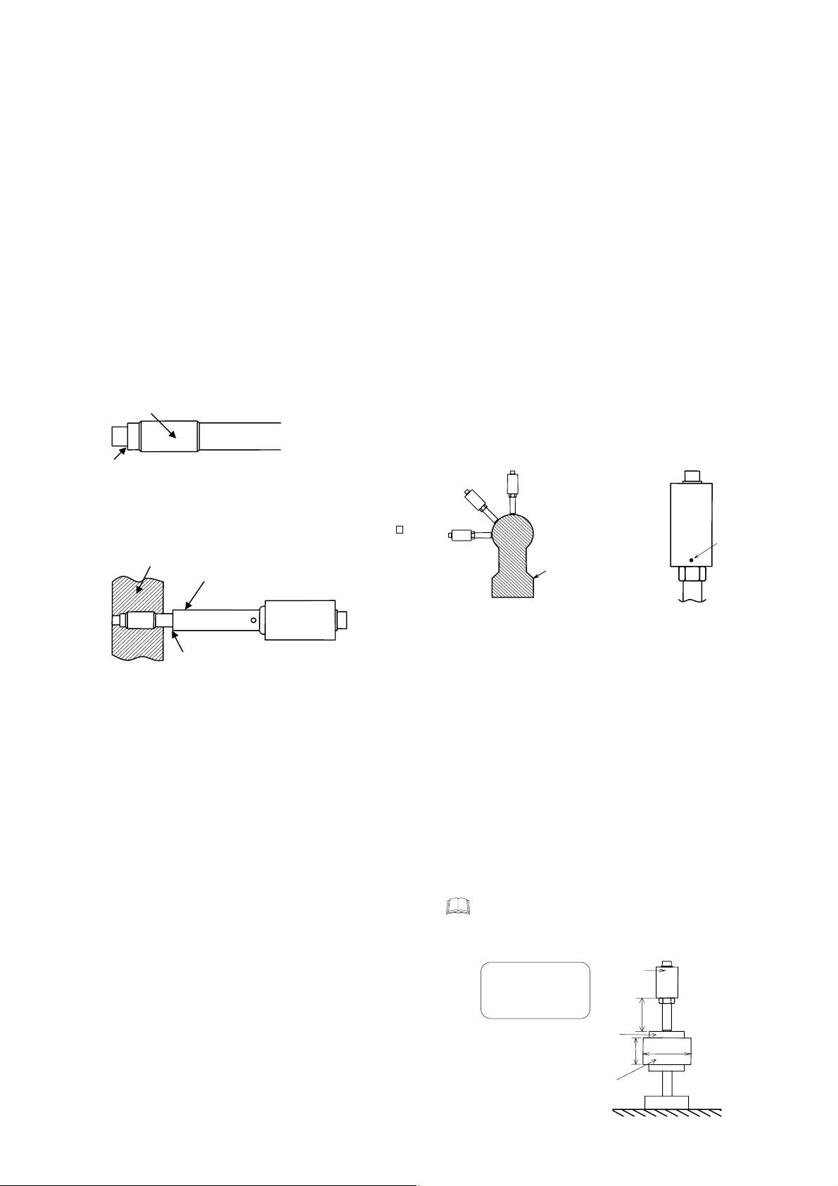
Mounting pressure sensors
• When the diaphragm at the end of CZ-100P and its surroundings
completely touch with its mounting hole, large indication error may
occur. In this case, temperature may exert a large influence
especially upon the zero point. Therefore, much attention should
be paid when a mounting hole is drilled.
Do not wind sealing tapes, etc. round this section
reventing oil or resin leakage.
for
Packing surface (Sealing surface)
[Flat tightening or tapered tightening surface]
(Oil or resin leakage is prevented at this point.)
• When using a lead pipe cover (option), pay attention that the lead
pipe cover end does not directly touch the barrel. (See the “
Exposed length at the bottom of the sensor outer case”)
Barrel
Lead
e cover (option)
Mount the sensor so that this block
does not directl
touch the barrel.
• Prior to mounting the pressure sensor, check the appearance of
the diaphragm. If the diaphragm has a deformed or abnormal end,
it needs to be repaired or re-calibrated. As there is a case where
the diaphragm is already deformed by the application of overload
when used previously, carefully check its condition before the
pressure sensor is re-used.
Mounting hole
• When mounting the pressure sensor, check its mounting hole
dimensions. (Do not overtighten its screw.)
• If resin or its carbide still remains in the mounting hole, this may
damage the pressure sensor. Therefore, prior to mounting the
sensor, always remove any residue from the mounting hole.
• Check that the diaphragm surface does not protrude from the
inner wall of the barrel, since this may score the diaphragm
surface with the screw, etc. If necessary, adjust the position
between the diaphragm surface and the inner wall of the barrel
using stainless steel packings, etc.
• For the loose nut type, resin leakage may occur more easily than
the fixed nut type, as the pressure sealing surface becomes wider.
If any resin leaks through the mounting gap of the sensor, use
copper packings (thickness: t = 2 mm) or aluminum packings
(thickness: t = 2 mm) by taking into account the position between
the diaphragm surface and the inner wall of the barrel. (Copper
Packing: Included in only the Loose nut type)
IM100CZ04-E2
Mounting direction
• If the sensor is installed in the upright direction (Fig.1-A), it may be
affected directly by heat flow from heater or heat source (rising
current of heated air). In such a case, the temperature of the strain
gauge in the sensor may exceed an allowable maximum
temperature of 150 °C. In order not to exceed this limit
temperature, it is necessary to keep the sensor outer cylinder
surface at a temperature of less than 134 °C (Fig.2). Conduct the
following treatments.
1. In order to avoid heat flow, wind a heat insulating material round
such a heat source (heater, etc.).
2. Further extend the length of the exposed lead pipe.
• In order to keep the specified sensor performance longer, it is
recommended that the sensor outer cylinder surface temperature
be keep at less than 134 °C.
• When the sensor is installed in the upright position, thermal effects
on the sensor may not sufficiently lessen even if the length of the
exposed lead pipe is further extended. In this case, take measures
of 1.
• The effect of heat flow lessens as the installing direction of the
sensor changes from the slanting direction (Fig.1-B) to the
horizontal direction (Fig.1-C) in this order. In this case, take
measures of 1 and 2 if necessary by checking the sensor outer
cylinder surface temperature. (To the relevant manufacturer: It is
recommended that the sensor be installed in the horizontal or
slanting direction in order to lessen the effect of heat on the strain
gauge.)
B
C
: Upper mounting
B: Oblique mounting
C: Side mounting
A section of a extruder
(Figure 1)
Exposed length at the bottom of the sensor
outer case
• Cases where the temperature of the strain gauge in the sensor
become less than 150 °C is as follows:
− The effect of heat flow is small.
− The sensor is installed in the upright position.
− The diaphragm is at a temperature of 400 °C.
− The length of the exposed sensor outer cylinder is more than 70
mm. (Refer to Fig. at the right)
However, as the effect of heat flow from an actual extruder is
serious, if there is no enough exposed section below the sensor
outer cylinder even at a diaphragm temperature of less than 200
°C, the operating temperature of the sensor strain gauge may
exceed its limit. Therefore, check the temperature environment
where the sensor is installed (by indirectly checking the
temperature of the sensor outer cylinder surface), and take
necessary measures to lessen the temperature of the sensor
strain gauge by using a heat insulating material, if necessary.
If the temperature of the sensor outer cylinder surface
exceeds 160 °C, the outer cylinder surface changes its
color from black to dark brown and then brown in this
order. If it exceeds 180 °C, the color may change to silver.
Mounting environment:
mbient temperatures
at room temperatures
25 °C
Mounting adapter
Temperature of heater
CZ-100P
60
70
φ90
400 °C
The aims of a
temperature
measurement
position
(Figure 2)
3
Page 4
A
A
A
• A lead pipe cover (option of HB and HC type) is mainly for protecting
the exposed section below the sensor outer cylinder from being
exposed to cold wind. Do not install the sensor such that it is
embedded in the heat source (such as in the barrel or heater)
together with the lead pipe cover. This may heighten thermal
conductivity from the heat source, resulting in a temperature
increase in the sensor strain gauge.
3.2 Caution in Removing Pressure
Sensors
• Always remove the sensor while resin is being melted, since
the diaphragm of the sensor may be damaged if the sensor is
removed after the resin has hardened. If the sensor is re−mounted
under this condition the repeatability may deteriorate.
• When removing the pressure sensor, remove it under the same
temperature as that during installation. Removing the pressure
sensor under the different temperature as that during installation
cause irregular engagement of the thread.
• If resin flows into the gap between the lead pipe and the mounting
hole, it may be impossible to remove the sensor even with the
threads completely disengaged. In this case, if the sensor is
forcibly removed using a puller, the sensor may be knocked when
removed, damaging the diaphragm and reducing the accuracy.
Slowly remove the sensor without knocking it.
• Remove the resin attached to the pressure sensing part
(diaphragm and its surrounding section) after melting it by
applying light heat to the side of the pressure sensing part using a
burner (Do not let the temperature exceed 400 °C). In addition,
care should be taken not to scratch the pressure sensing block. If
not, diaphragm damage or resin leakage may result.
3.3 Cautions during Extruder Cooling
Down
If the temperature is decreased while resin remains in the extruder
with the pressure sensor installed, the diaphragm may be depressed
and deformed by resin contraction, etc. As a result, a measurement
error or pressure dead-band may occur. If the extruder is cooled
down, completely remove all the resin remaining in the barrel, or
remove the sensor. Especially take care for the low pressure sensor,
as this effect becomes serious.
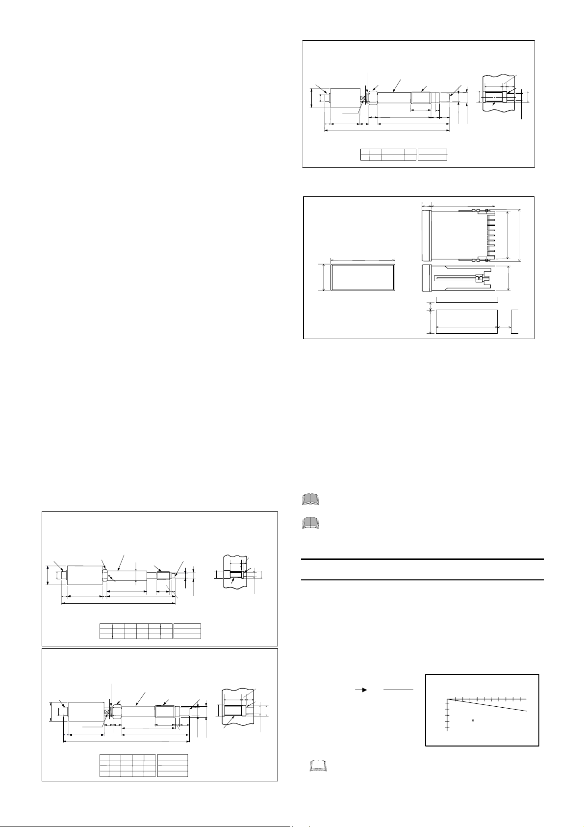
3.4 Dimensions
Resin pressure sensor (CZ-100P)
CZ-100P-
Unit:
mm
Connector receptacle
PRC03-23A10-7F
19
φ42
φ
CZ-100P-HL
CZ-100P-HL
Unit:
mm
Connector receptacle
PRC03-23A10-7F
φ42
φ19
Flat head bolt 14
Measurement range: 0 to 20 MPa, 0 to 35 MPa, 0 to 50 MPa, 0 to 70 MPa,
HB
HC
Hexagon flat
head bolt 23
Set screw
103 + L
Standard Dimensions
HB
150
180
HC
(Loose nut type)
(Low pressure loose nut type)
C type snap ring
Hexagon flat
head bolt 27
17
φ
20
20 L3
80 13
Standard Dimensions
L
146
B
195
250
C
Lead pipe cover
(SUS304)
L
0 to 100 MPa
Tip pressure
receiving side:
21
φ
L4
L 80 13 10
L1
8
8
Lead pipe cover
120
133 + L
L1
L2
20
20
20
110
PF3/8
(JIS B grade)
L2
(SUS403)
6
55
Diaphragm (SUS630)
L2
0
−0.2
−0.2
−0.1
L3
10
φ
φ14
0
L1
−
0.2
Weight
L3 L4
30
90
30
(JIS B grade)
L
L3
45
45
45
Approx. 650g
120
Approx. 700g
PF3/4
Weight
Approx. 0.9kg
Approx. 1.0kg
Approx. 1.2kg
0 to 70 MPa, 0 to 100 MPa
Tip pressure
receiving side:
Diaphragm
(SUS630)
0
L1
−
0.2
0.2
−0.1
−
L2
φ18
4
4
Measurement range: 0 to 20 MPa, 0 to 35 MPa, 0 to 50 MPa,
Measurement range: 0 to 5 MPa, 0 to 10 MPa
Mounting Hold Dimensions
L1
L3
Seal surface
L2+1
20
φ
Element finished to JIS B grade.
Finish to allow loose fitting.
Mounting Hold
Dimensions
30
φ
−0.1 −0.2
PF3/4
24
φ
Element finished to JIS B grade.
Finish to allow loose fitting.
PF3/8
L3 L2L1
±0.1
10.3
φ
Seal
surface
18
φ
φ28
±0.1
φ18.3
CZ-100P-LL
Unit:
mm
Connector receptacle
PRC03-23A10-7F
19
φ40
φ
Flat head bolt
6013
14
C type snap ring
Hexagon flat
head bolt 23
φ17
20
113 + L
Standard Dimensions
146L20L16L245
Measurement range: 0 to 0.5 MPa, 0 to 1 MPa
Lead pipe cover
(SUS403)
(JIS B grade)
L3
12020
L
L3
PF3/4
6
L2
Weight
Approx. 0.9kg
Tip pressure
receiving side:
Diaphragm
(SUS630)
0
L1
−
0.2
−0.1
−0.2
−0.1
φ18
Mounting Hold
Dimensions
L3 L1
30
φ
PF3/4
−0.2
24
φ
Element finished to JIS B grade.
Finish to allow loose fitting.
Output converter (PCT-300)
(U nit: m m )
96
48
Panel cutout dimensions
12
100
25 45
0.6
0
+
92
+ 0.8
0
3.5 Pressure Sensor Installation
1. Make sure the mounting hole is correctly machined. If installing
the pressure sensor into a previously used hole, make sure the
hole is thoroughly cleaned to remove any plastic residue.
2.
Lubricate the threads with a high temperature anti-seize lubricant.
3.
Tighten the hexagon nut part with a torque wrench. When tightening
the pressure sensor, always tighten only the hexagon nut part.
• Fixed nut type (PF3/8 thread: HB, HC type) : 30.0 Nm
[300 kgfcm]
• Loose nut type (PF3/4 thread: LB, LC type) : 60.0 Nm
[600 kgfcm]
• Fixed nut type (Unified thread: UB, UC type) : 30.0 Nm
[300 kgfcm]
Tighten the pressure sensor to secure it after the
temperature rises.
Do not tighten any block other than the hexagonal nuts,
since this may damage the pressure sensor.
4. WIRING
4.1 Wiring Precaution
• The CZ-100P (sensor) connect to the PCT-300 (output converter)
using the 4-core shielded cable attached.
• The rated output of the CZ-100P (mV/V: Described on the
nameplate adhered) is obtained when standard cable length is 5
m. If cable length is extended beyond the above figure, correct the
rated output in accordance with the following equation.
Equation:
e1 = e2 (1+ Kl)
: Rated output in standard cable le ngth of 5 m
e1
(mV/V : Described on the nameplate adhered)
: Rated output after cable extens ion
e2
: Correction factor* 1.96 × 10
K
[Non-explosionproof specificatio n type]
* When 0.5 mm
cable) or same as standard cable is used.)
: Extended cable length (m)
l
2
× 4-core shielded cable (standard
For the explosionproof specification type, the K value
becomes “1.40 × 10
e2 =
4
−
/m
e1
1+ Kl
Rated
output
change
Figure: Rated output change with cable extended
4
−
/m.”
0
−5
[%FS]
Extended cable length
50 100 (m)
2
×
4-core shielded cable
0.5 mm
30
L2
Seal
surface
φ28
±0.1
18.3
φ
91
(100)
43
IM100CZ04-E2
4
Page 5
A
−
A
A
+
−
+
A
A
A
×1 ⇔
• If the pressure sensor is used together with the output converter
(Model PCT-300), always connect a grounding wire to the
equipment side. (Ground the grounding terminal.)
• Connect a grounding wire to the extruder.
• For a heat-resistant glass covered cable, the cover is made of
fibers. Therefore, the electrical insulation may deteriorate if the
cable is exposed to high humidity or conductive liquid (water, etc.)
and cause a pressure indication error. For this reason, avoid
underground wiring or wiring within electric conduits passing
through humid areas as much as possible.
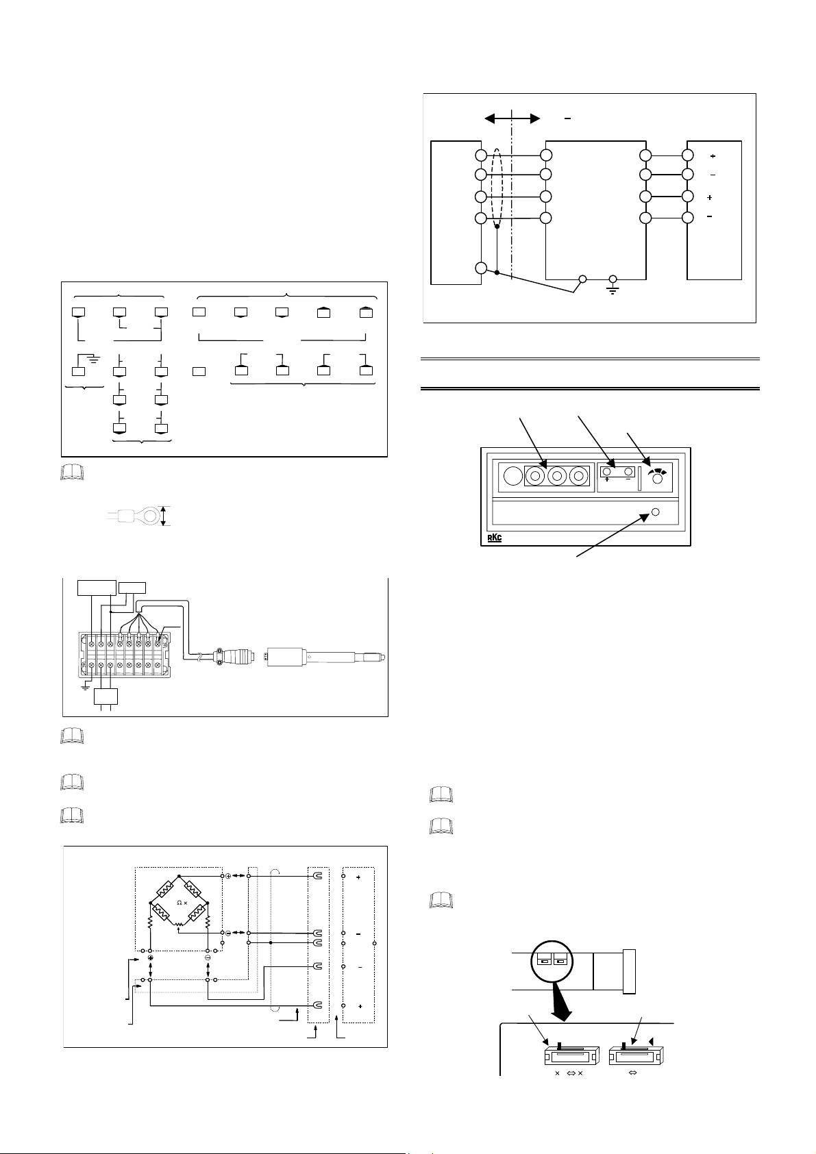
4.2 Wiring Method
Terminal configuration figure of output
converter (PCT-300)
9 10 11 12 13 14
OUT2
+
0 to 10 mV DC
OUT1
+
0 to 10 V DC
C
L
1 2
Grounding
terminals
100 to 240 V
L
AC 24 V
2
+
DC 24 V
2
Power terminals
Do not excessively tighten the terminal screws. In addition,
use the solderless terminal appropriate to the screw size
SHD
(E)
−
−
N
4 5 6 7 8
3
N
3
−
3
For two output points: Use OUT1 and OUT2
For three output points: Use OUT1 to OUT3
For four output points: Use OUT1 to OU T4
Input terminals Output terminals
EXC+
EXC−
(A)
(C)
SENSOR
OUT3 OUT4
+
1 to 5 V DC 4 to 20 mA DC
15 16
SIG+
(D)
+
−
Output terminals
SIG−
(B)
(M3).
8.1 mm or less
Recommended tightening torque:
0.4 Nm [4 kg fcm]
Max. 1.0 Nm [10 kgfcm]
Wiring
Pressure
Output converter
PCT-300
indicator
Power
supply
Recorder
100 to 240 V AC
or
24 V AC/DC
Crimp-style
terminal lug
Connection cable
Plug
Pressure sensor (CZ-100P)
Do not place magnet relays or any other equipment which
causes magnetic disturbance near the output converter.
Install the power cable away from the 4-core shielded cable.
When connecting the sensor to a pressure indicator or
recorder, check its polarity and output signal.
NDI standardized connector (plug, receptacle and jack) is
used.
Wiring diagram of connector and cable
Receptacle
(PRC03-23A-7F)
Plug
(PRC03-12A10-7M)
CZ-100P
× 4
350
Ω
+ F A
Applied
voltage
F
C G
+
D
D
B
B
−
E
−
C G
Standard 4-core shield cable
(Insulator color)
E
Crimp- style lug t erminal
Blue
Black
Shield
Brown
Red
D
B
E
C
PCT-300
15
SIG
(D)
16
(B)
SIG
−
G
SHD (E)
12
(C)
EXC
14
13
(A)
EXC
Terminal No.
Grounding terminal
Wiring example of explosionproof specification
sensor
Instrument configuration diagram
Hazardous
area
C
D
B
Red
Brown
Blue
Black
Non
hazardous area
−
C
D
B
Red
Brown
C
Blue
D
B
Black
RZB-001A
Safety barrier
Pressure sensor (CZ-100P)
* CT-300E, PCT-300E, REX-PG410
E G
Ground
5. ADJUSTMENT
Gain setter Monitor plug
Zero adjuster
1.
Power lamp
Adjustment procedures
1. Check the rated output (mV/V) described on the nameplated of
the CZ-100P (This output should be corrected when the cable is
extended.) and then set that value on the rotary switch which is
gain setter of the PCT-300.
2. The pressure reading zero point is adjusted by the zero adjuster
in PCT-300. Perform this zero adjustment after the position
installed with CZ-100P on the extruder reaches the desired
temperature and is in the steady state after the lapse of a certain
time. If an indicator is not available, adjust the zero point on the
monitoring terminals using a circuit tester. In addition, perform
the above adjustment after warming up for 20 minutes or more
with the power switch of PCT-300 turned ON (power lamp lights)
after wiring has been finished.
When the gain setter and zero adjuster are set using small
screwdriver.
When the sensor is provided with the gain selection function
(option), the output value is doubled if the function is set to
“×2”, which is effective for increasing the reading at
low-pressure. The valid range is within the output range of
PCT-300, which corresponds to half of full-scale pressure.
Turn this switch to the OFF side (100 Hz, −3 dB) when
quick response is required. The filter switch is turned to the
ON side (10 Hz, −3 dB) prior to shipment.
GAIN switch
(optional)
mV/V
−
+
MONI
ZERO
PWR
PCT-300
FILTER switch
ON ⇔ OFF
2
×
EXC
EXC
SIC
SIC
*
+
−
+
−
Converter or Indicator
IM100CZ04-E2
5
Page 6
6.
LINEARIZING FUNCTION SETTING
To prevent electric shock and instrument failure,
always turn off the power supply before pulling out the
internal chassis.
To prevent injury or instrument failure, do not touch the
internal printed circuit board.
!
WARNING
Linearizing switch changing
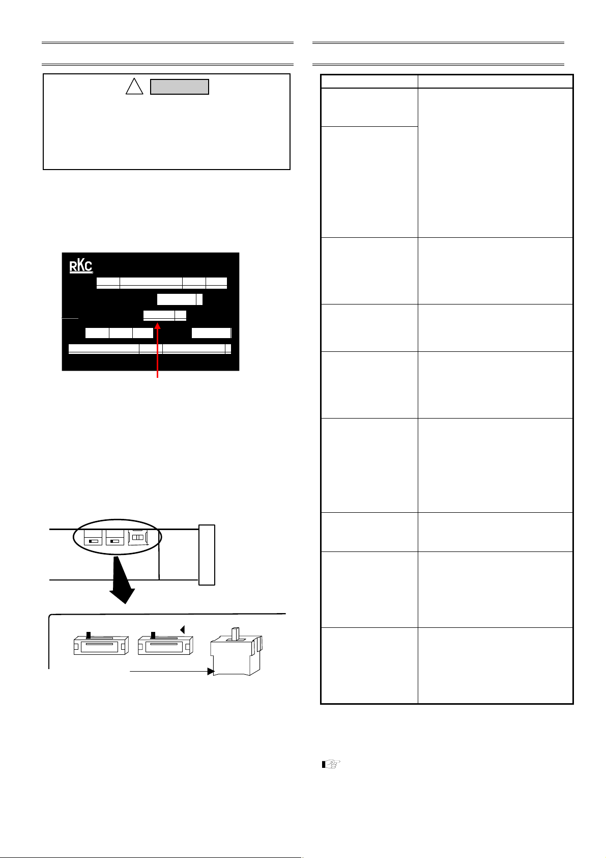
1. First check the output characteristic type (A, N or B) engraved at
the end of the figure showing the rated output value on the rating
nameplate attached to the outer chamber of the pressure
sensor.
Example: Rating nameplate
PRESSURE SENSOR
CZ-100P-HB-SNE
TYPE
PRESSURE RANGE
RATED OUTPUT
97J21020
No.
1.234 A
0 - 20
DATE
MPa
mV/V
9710
RKC INSTRUMENT INC. TOKYO JAPAN
A, N or B is engraved in this section.
For products other than corresponding to the linearizing
function, the output characteristic type (A, N or B) is not
engraved in this section.
2. Next, check that the power to the PCT-300 output converter is
turned off, then remove the internal assembly from the case.
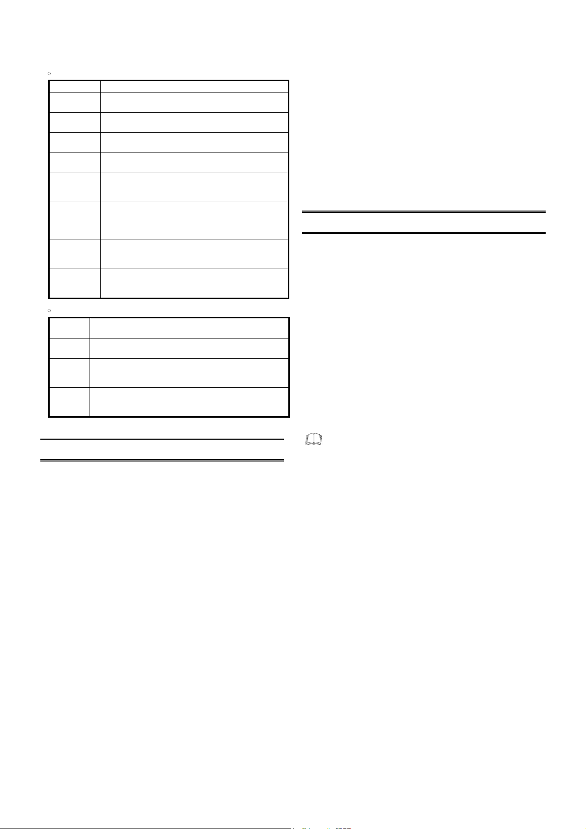
3. Set the linearizing switch on the side of the internal assembly of
the PCT-300 to the position matching the output characteristic
type of the pressure sensor to be connected.
Internal assembly of PCT-300
Upper
Front
Lower
GAIN
X1X2
Linearizing switch:
Set the switch to the position matching the
output characteristic type of the pressure
sensor.
The gai n or lin earizing switch is optional. The figure on the left
side shows all the optional switches to simplify th e explanation.
FILTER
ON
ON↔OFF
4. House the internal assembly in the case. This completes the
setting.
7. TROUBLES AND CAUSE
Problem Probable cause
Indication pointer
completely defects to the
left or right.
Digital display ove-scale or
underscale.
No pressure is indicated
under pressurized
condition.
Pointer or indication
fluctuates during relay
actuation.
Pressure indication is
fluctuated.
Normal operation was
performed, but no reading
was received after a while
or the reading varied and
was unstable.
Indication fluctuates from
the beginning.
Resin leakage.
No threads regularly
engaged (no screw
removed).
• No indicator input circuit connected.
• No 4−conductor shielded cable connected.
• The defective connector used (standard or
water resistant connector).
• Wires disconnected or shorted.
• No internal sensor wiring connected.
• The fiberglass coated cable immersed into
water or exposed to high temperature, resulting
in deteriorated insulation resistance.
• No rated output set to the PCT-300
(different gain).
• The double gain SW. turned ON.
•
The strain gauge deteriorated due to exposure
to high temperature.
• No zero adjuster adjusted.
• The zero range select SW. switched.
•
Irregularly tapped hole for installing the CZ−200P.
(The sensor tip strongly contacting with the
tapped hole.)
• The diaphragm deteriorated, deformed or
damaged.*
•
Mechanical Lead pipe deformation by external
force.
• No measures for relay spark killing taken.
• No 4−conductor cable shield perfectly wired
or grounded.
• The PCT-300 located near magnetically
operated relays.
•
Value different from the sensor rated output set
to the rated output setter for the PCT-300.
• The diaphragm deteriorated, deformed or
damaged.*
• The sensor exposed to hot or cold wind.
• Some potential against the earth generated
(2−point grounding, etc.).
• Imperfect connecter contact.
• The lead pipe deformed by external force.
• The diaphragm deteriorated, deformed or
damaged.*
• The fiberglass coated cable immersed into
water or exposed to high temperature, resulting
in deteriorated insulation resistance.
• The sensor exposed to hot or cold wind.
• The extruder now in unstable operation or
temperature rise.
• The sensor tip forcibly tightened due to the
small tapped hole.
•
The lead pipe cover contacting with the barrel,
etc.
• The sealed surface deformed or scratched.
• Foreign material (carbide, etc.) attached on
the sealed surface.
• Low sealed surface accuracy (parallelism,
axis, etc.).
No screw threaded down to the extreme end.
•
• Tightened at less than appropriate torque or
not tightened.
•
No screw threaded down to the extreme end.
•
Not threaded as conforming to the standard.
• The screw with burrs used.
• Tightened at excessive torque.
• Tightened at temperature different from the
initial tightening temperature.
• Foreign material attached on the threaded
section, or stained.
For taking measures, also refer to “4. HANDLING OF THE
PRESSURE SENSOR.” The converter is described on a basis of
the PCT-300. The operation of the PG-410 may differ from that of
the PCT-300 described here.
For the cause of diaphragm deterioration, deformation or
damage, refer to the following “ * Main causes.”
Continued on the next page.
IM100CZ04-E2
6
Page 7
* Main causes:
These causes may arise independently or in mutual relations.
Generative cause in operation
•
Overpressure Load pressure exceeding its limit applied.
Irregular thread
engagement
Metal fatigue The metal sensing surface fatigued by the application of
Corrosion The pressure sensing surface corroded due to its contact
Abrasion
Shrinkage
Separation The pressure sensing surface deformed or damaged by
Protrusion
Contact The pressure sensing surface deformed due to the forced
The metal pressure sensing surface mechanically scratched
or chipped off.
changing or repeating pressure.
with corroding material.
The pressure sensing surface worn away due to the mixture
of fillers, etc.
The pressure sensing surface deformed due to the shrinkage
of resin adhered to its surface as a result of extruder cooling
down.
resin adhered to its surface due to the removal of the sensor
while the resin is not yet melted or its melted condition is
imperfect.
The pressure sensing surface deformed or damaged due to
the protrusion of the push rod from the lead pipe as a result
of an external force applied by the screen changer, etc.
contact of the sensor outer side with the hole inner surface
as a result of the finish of the hole inner surface.
•
Generative cause in mounting and removing
Impact
Dropping
Handling After the resin attached to the sensor tip is heated by a gas
Excessive
tightening
The pressure sensing surface deformed due to its strong strike
with solid material.
The pressure sensing surface or its circumference scratched or
deformed due to sensor dropping.
burner, etc. for its removal at the time of inspection, the pressure
sensing surface scratched with a metal brush, etc.
The diaphragm deformed or damaged as the push rod pushes
the diaphragm from the inside as a result of the deformation of
the sensor flange by excessive tightening torque.
EXPLANATION OF EACH TERMS
8.
• Rated pressure
The maximum pressure which satisfies the specification. There
are stipulated pressure ranges.
• Rated output
Value obtained by subtracting the output at no-load from that at
the rated pressure load. Electrically, it is output voltage (mV) per
V DC (application voltage) in the bridge circuit output at the rated
pressure load. At an application voltage of 10 V from the converter,
a voltage of mV × 10 is output.
• Accuracy
The maximum error including linearity and hysteresis.
• Linearity
The maximum error from a reference line (straight line without
error) when pressure-loaded in the pressure rise direction
continuously from no-load to the rated pressure.
• Hysteresis
The maximum difference between pressures at the same point in
the rise and fall directions when the same pressure is loaded.
• Repeatability
The difference between measured values obtained each time
when pressure-loaded three times repeatedly from no-load to the
rated pressure within a short period of time*.
• Temperature effect on zero point
Zero-point output variation when the diaphragm temperature
changes by 10 °C.
• Temperature effect on output (sensitivity)
Output sensitivity (span) variation when the diaphragm
temperature changes by 10 °C.
• Allowable overpressure
The high limit of overpressure within a short period of time* at
which the accuracy can be guaranteed even after the pressure
returns to the rated pressure when overpressure-loaded.
• Limit overpressure
The high limit of overpressure within a short period of time* at
which no diaphragm is damaged when overpressure-loaded.
However, no accuracy is guaranteed after the pressure returns to
the rated pressure.
* Short period of time: From several seconds to several minutes.
9. SPECIFICATIONS
9.1 Resin Pressure Sensor (CZ-100P)
Sensing block construction:
4−side adhesion−type strain gauge, wheatstone bridge
Rated pressure:
Fixed nut type: 20 MPa, 35 MPa, 50 MPa, 70 MPa, 100 MPa
Loose nut type (LL type):
5 MPa, 10 MPa
Loose nut type (HL type):
20 MPa, 35 MPa, 50 MPa, 70 MPa, 100 MPa
Loose nut type (LLA type):
0.5 MPa *, 1 MPa
CT−300 (the ZK−872 specification) or REX−PG410
Rated output
[Calibration temperature: At diaphragm temperature of 150 °C]:
1.2 to 1.8 mV/V
1.0 to 1.6 mV/V (For the LLA type “0 to 1 MPa” range)
0.5 to 0.8 mV/V (For the LLA type “0 to 0.5 MPa” range)
The output of each sensor becomes a specific value within the
range of 1.2 to 1.8 mV/V.
Bridge impressed voltage:
10 V DC (When using PCT−300, or CT−300),
7.7 V DC (When using REX−PG410)
Accuracy [At diaphragm temperature of 150 °C]:
SUS630 diaphragm specification type:
± 1.0 % of span (the range of 70 MPa or less),
± 2.0 % of span (the range of more than 70 MPa)
HASTELLOY C diaphragm specification type:
± 1.0 % of span (the range of 50 MPa or less),
± 2.0 % of span (the range of more than 50 MPa)
Linearity [At diaphragm temperature of 150 °C]:
Same as Accuracy
Hysteresis [At diaphragm temperature of 150 °C]:
SUS630 diaphragm specification type:
± 1.0 % of span (the range of 70 MPa or less),
± 2.0 % of span (the range of more than 70 MPa)
± 0.2 % of span (LLA type)
HASTELLOY C diaphragm specification type:
± 1.0 % of span (the range of 50 MPa or less)
± 2.0 % of span (the range of more than 50 MPa)
Repeatability [At diaphragm temperature of 150 °C]:
SUS630 diaphragm specification type: ± 0.2 % of span
HASTELLOY C diaphragm specification type: ± 0.4 % of span
Zero balance:
± 0.6 mV/V (± 40 % of span)
Bridge resistance:
Input side*: 374 ± 10 Ω, Output side: 350 ± 5 Ω
* As the input side of bridge resistance, the 350 ±5 Ω type is also available.
This type is interchangeable with the 374 ±10 Ω type.
* However, this range can be used when combined with the
IM100CZ04-E2
7
Page 8

Maximum diaphragm:
400 °C
Maximum strain gauge temperature:
150 °C
When the temperature at the bottom of outer tube (nut side)
is more than 134 °C, the temperature at the strain gauge
exceed 150 °C.*
* If the temperature at the strain gauge exceed 150 °C, the performance
cannot be assured. Therefore, cover the heat source with a heat
insulating material so that the above temperature does not exceed
150 °C.
The temperature at the strain gauge can be expected not to rise when:
• the long type of sensor is used or
• the sensor is installed aslant or transversely.
If any of the above measures can be taken, take it.
Zero shift due to temperature change:
SUS630 diaphragm specification type
[As to diaphragm temperature]:
0.2 % of span/10 °C
HASTELLOY C diaphragm specification type
[As to diaphragm temperature]:
0.3 % of span/10 °C
(0.5 MPa: 0.4 % of span/10 °C)
Output (sensitivity) shift due to temperature change:
Same as Zero shift due to temperature change
Allowable over pressure:
120 % of span (0.5 MPa: 1000 % of span, 1 MPa: 500 % of span)
Limited over pressure:
150 % of span (0.5 MPa: 2000 % of span, 1 MPa: 1000 % of span)
Diaphragm material:
SUS630 (Standard), HASTELLOY C (Optional)
Diaphragm surface treatment:
Non surface treatment (Standard),
CERAMIC Kanigin plate (Optional)
Fixing screw section material:
SUS403
Lead pipe cover material:
SUS304 (Fixed nut type only)
Recommended tightening torque:
Fixed nut type: 30 Nm (300 kgfcm)
Loose nut type: 60 Nm (600 kgfcm)
9.2 Output Converter (PCT-300)
•
Input
Input sensor:
Strain gauge type sensor
[Resin pressure sensor (CZ-100P: RKC product)]
Input range:
Standard specification:
0 to 19.99 mV (Excluding bias portion that allows zero adjustment)
Explosion-proof construction specification:
0 to 11.6 mV (Excluding bias portion that allows zero adjustment)
Input impedance:
1 MΩ or more
Action at input break:
Upscale (The sensor power supply break is the same)
•
Sensor power supply
Applied voltage:
Standard specification: 10 V DC (Normal current 28 mA)
Explosion-proof construction specification:
8.2 V DC (Normal current 16 mA)
Accuracy:
Within +0.1 %, −0.4 %
Temperature drift:
30 ppm/°C or less
•
Zero point
Adjustment range:
Standard specification:
±7 mV (Input conversion)
Explosion-proof construction specification:
±6 mV (Input conversion)
Temperature drift:
Within +0.02 % of span/°C
Gain
•
Adjustment range:
Standard specification:
Input range “10.00 to 19.99 mV” can be used as rating (10 V etc.).
Explosion-proof construction specification:
Input range “5.80 to 11.60 mV” can be used as rating (10 V etc.).
Setting accuracy:
Within +0.2 % of span/°C
Temperature drift:
100 ppm/°C or less
Optional functions:
Gain selector switch provided (Selection 1× ⇔ 2×)
•
Output
Output type:
0 to 10 V DC (Load resistance: 2 kΩ or more)
0 to 10 mV DC (Load resistance: 10 kΩ or more)
0 to 5 V DC (Load resistance: 1 kΩ or more)
4 to 20 mA DC (Load resistance: 600 Ω or less)
Monitor voltage:
0 to 10 V DC (Pin size of tester conforming: φ 2.0)
•
General specifications
Linearity:
Within ± 0.01 % of span
Noise:
Within ± 0.1 % p-p of span (0.1 to 10 Hz)
Response:
10 Hz/100 Hz transfer type [Factory shipment: 10 Hz]
Power supply:
90 to 264 V AC (power supply voltage range),
Compatible 50 Hz/60 Hz, Rated: 100 to 240 V AC
21.6 to 26.4 V AC (power supply voltage range),
Compatible 50 Hz/60 Hz, Rated: 24 V AC
21.6 to 26.4 V DC (power supply voltage range), Rated: 24 V DC
Power consumption:
12.5 VA max. (at 240 V AC), 7.5 VA max. (at 100 V AC),
8 VA max. (at 24 V AC), 190 mA max. (at 24 V DC)
Insulation resistance:
Between input/output terminal and grounding:
20 MΩ or more at 500 V DC
Between power terminal and grounding:
20 MΩ or more at 500 V DC
Withstand voltage:
Between input/output terminal and grounding:
1 minute at 1000 V AC
Between power terminal and grounding:
1 minute at 1500 V AC
Weight:
Approx. 290 g
•
Operating environment
Allowable ambient temperature:
0 to 50 °C
Allowable ambient humidity:
45 to 85 % RH (Non condensing)
Ambient operating atmosphere:
There should be neither corrosive gases nor much dust.
The first edition: APR. 1995
The second edition: MAY 2004 [IMQ00]
HEADQUARTERS: 16-6, KUGAHARA 5-CHOME, OHTA-KU TOKYO 146-8515 JAPAN
RKC INSTRUMENT INC.
®
PHONE: 03-3751-9799 (+81 3 3751 9799) E-mail: info@rkcinst.co.jp
FAX: 03-3751-8585 (+81 3 3751 8585)
IM100CZ04-E2 MAY 2004
 Loading...