

Page 1

6
6
OPC-V
Operation Manual
Operation Panel
0
[For SRZ]
E
RKC INSTRUMENT INC.
®
IMS01T08-E1
Page 2

Modbus is a registered trademark of Schneider Electric.
Company names and product names used in this manual are the trademarks or registered trademarks of
the respective companies.
All Rights Reserved, Copyright 2006, RKC INSTRUMENT INC.
Page 3

Thank you for purchasing this RKC instrument. In order to achieve maximum performance and ensure
proper operation of your new instrument, carefully read all the instructions in this manual. Please place this
manual in a convenient location for easy reference.
SYMBOLS
WARNING
CAUTION
!
: This mark indicates where additional information may be located.
An external protection device must be installed if failure of this instrument
could result in damage to the instrument, equipment or injury to personnel.
: This mark indicates precautions that must be taken if there is danger of electric
shock, fire, etc., which could result in loss of life or injury.
: This mark indicates that if these precautions and operating procedures are not taken,
damage to the instrument may result.
: This mark indicates that all precautions should be taken for safe usage.
: This mark indicates important information on installation, handling and operating
procedures.
: This mark indicates supplemental information on installation, handling and
operating procedures.
WARNING
!
All wiring must be completed before power is turned on to prevent electric
shock, fire or damage to instrument and equipment.
This instrument must be used in accordance with the specifications to
prevent fire or damage to instrument and equipment.
This instrument is not intended for use in locations subject to flammable or
explosive gases.
Do not touch high-voltage connections such as power supply terminals, etc.
to avoid electric shock.
RKC is not responsible if this instrument is repaired, modified or
disassembled by other than factory-approved personnel. Malfunction can
occur and warranty is void under these conditions.
IMS01T08-E1
i-1
Page 4

CAUTION
This is a Class A instrument. In a domestic environment, this instrument may cause radio
interference, in which case the user may be required to take adequate measures.
This instrument is protected from electric shock by reinforced insulation. Provide reinforced
insulation between the wire for the input signal and the wires for instrument power supply,
source of power and loads.
Be sure to provide an appropriate surge control circuit respectively for the following:
- If input/output or signal lines within the building are longer than 30 meters.
- If input/output or signal lines leave the building, regardless the length.
This instrument is designed for installation in an enclosed instrumentation panel. All
high-voltage connections such as power supply terminals must be enclosed in the
instrumentation panel to avoid electric shock by operating personnel.
All precautions described in this manual should be taken to avoid damage to the instrument or
equipment.
All wiring must be in accordance with local codes and regulations.
All wiring must be completed before power is turned on to prevent electric shock, instrument
failure, or incorrect action.
The power must be turned off before repairing work for input break and output failure including
replacement of sensor, contactor or SSR, and all wiring must be completed before power is
turned on again.
To prevent instrument damage or failure, protect the power line and the input/output lines from
high currents with a protection device such as fuse, circuit breaker, etc.
Prevent metal fragments or lead wire scraps from falling inside instrument case to avoid
electric shock, fire or malfunction.
Tighten each terminal screw to the specified torque found in the manual to avoid electric shock,
fire or malfunction.
For proper operation of this instrument, provide adequate ventilation for heat dispensation.
Do not connect wires to unused terminals as this will interfere with proper operation of the
instrument.
Turn off the power supply before cleaning the instrument.
Do not use a volatile solvent such as paint thinner to clean the instrument. Deformation or
discoloration will occur. Use a soft, dry cloth to remove stains from the instrument.
To avoid damage to instrument display, do not rub with an abrasive material or push front
panel with a hard object.
Do not connect modular connectors to telephone line.
NOTICE
This manual assumes that the reader has a fundamental knowledge of the principles of electricity,
process control, computer technology and communications.
The figures, diagrams and numeric values used in this manual are only for purpose of illustration.
RKC is not responsible for any damage or injury that is caused as a result of using this instrument,
instrument failure or indirect damage.
RKC is not responsible for any damage and/or injury resulting from the use of instruments made by
imitating this instrument.
Periodic maintenance is required for safe and proper operation of this instrument. Some components
have a limited service life, or characteristics that change over time.
Every effort has been made to ensure accuracy of all information contained herein. RKC makes no
warranty expressed or implied, with respect to the accuracy of the information. The information in this
manual is subject to change without prior notice.
No portion of this document may be reprinted, modified, copied, transmitted, digitized, stored,
processed or retrieved through any mechanical, electronic, optical or other means without prior written
approval from RKC.
i-2
IMS01T08-E1
Page 5

CONTENTS
1. OUTLINE............................................................................ 1-1
1.1 Features .......................................................................................................1-2
1.2 Checking the Products .................................................................................1-4
2. PREPARATIONS ...............................................................2-1
2.1 Connections..................................................................................................2-2
2.1.1 Connection to the SRZ............................................................................................2-3
2.1.2 Installation of termination resistor ...........................................................................2-6
2.2 Communication Setting ................................................................................2-9
2.2.1 Module address setting........................................................................................... 2-9
2.2.2 Communication speed, data bit configuration and protocol setting .......................2-12
2.2.3 Confirmation of communication parameter of the OPC-V606E side .....................2-13
Page
2.3 Start-up Procedures ...................................................................................2-15
2.4 Contrast Adjustment ...................................................................................2-16
2.5 Set the Number of Connection Modules.....................................................2-18
3. SCREEN DESCRIPTIONS ................................................3-1
3.1 Screen Configuration....................................................................................3-2
3.2 Basic Operations ..........................................................................................3-6
3.2.1 Data settings ...........................................................................................................3-6
3.2.2 Text editing ...........................................................................................................3-10
3.3 Start-up Screen ..........................................................................................3-14
3.4 Operation Menu Screen .............................................................................3-17
3.4.1 Calling procedure of the operation menu screen ..................................................3-17
3.4.2 Operation menu screen.........................................................................................3-18
3.5 Monitor Screen ...........................................................................................3-19
3.5.1 Calling procedure of the monitor screen ...............................................................3-19
3.5.2 Basic configuration of monitor screen ...................................................................3-21
3.5.3 TIO monitor screen ...............................................................................................3-23
3.5.4 TIO alarm monitor screen .....................................................................................3-25
3.5.5 DIO monitor screen............................................................................................... 3-26
3.5.6 Configuration monitor menu 1 screen ...................................................................3-27
3.5.7 Configuration monitor menu 2 screen ...................................................................3-30
3.6 Trend Graph Screen...................................................................................3-33
3.6.1 Calling procedure of the trend graph screen .........................................................3-33
3.6.2 Trend graph screen...............................................................................................3-33
3.6.3 CH select screen................................................................................................... 3-35
IMS01T08-E1 i-3
Page 6

Page
3.7 Setting Screen ............................................................................................3-36
3.7.1 Calling procedure of the setting screen.................................................................3-36
3.7.2 TIO setting menu screen.......................................................................................3-38
3.7.3 Event setting menu screen....................................................................................3-39
3.7.4 PID setting menu screen.......................................................................................3-40
3.7.5 Other setting 1 menu screen.................................................................................3-41
3.7.6 Other setting 2 menu screen.................................................................................3-42
3.7.7 Basic configuration of setting screen ....................................................................3-43
3.7.8 Setting item list......................................................................................................3-44
3.8 Operation Mode Screen .............................................................................3-48
3.8.1 Calling procedure of the operation mode screen ..................................................3-48
3.8.2 Operation mode menu screen...............................................................................3-49
3.8.3 Basic configuration of operation mode screen ...................................................... 3-50
3.8.4 Operation mode item list .......................................................................................3-52
3.9 DO Setting Screen......................................................................................3-54
3.9.1 Calling procedure of the DO setting screen ..........................................................3-54
3.9.2 DO setting menu screen .......................................................................................3-54
3.9.3 Basic configuration of DO setting screen ..............................................................3-55
3.9.4 DO setting item list................................................................................................3-56
3.10 Initial Setting Screen.................................................................................3-57
3.10.1 Releasing procedure of the initial setting key protect.......................................... 3-57
3.10.2 Calling procedure of the initial setting screen......................................................3-59
3.10.3 Initial menu screen.............................................................................................. 3-63
3.10.4 Number of modules set screen ...........................................................................3-64
3.10.5 Clock set screen .................................................................................................3-65
3.10.6 Name setting menu screen .................................................................................3-66
3.10.7 Alarm message set screen..................................................................................3-67
3.10.8 TIO CH name set screen ....................................................................................3-68
3.10.9 Screen saver set screen .....................................................................................3-69
3.10.10 TIO controller initial menu screen .....................................................................3-70
3.10.11 Basic configuration of TIO controller initial screen ............................................ 3-71
3.10.12 TIO controller initial item list ..............................................................................3-73
3.10.13 DIO controller initial menu screen .....................................................................3-81
3.10.14 Basic configuration of DIO controller initial screen............................................ 3-82
3.10.15 DIO controller initial item list..............................................................................3-84
3.10.16 Password set screen......................................................................................... 3-88
i-4
3.11 Screen Setting Examples When Using DIO..............................................3-89
3.11.1 Example of using DI............................................................................................ 3-89
3.11.2 Example of using DO ..........................................................................................3-94
IMS01T08-E1
Page 7

OUTLINE
1.1 Features ...........................................................................................1-2
1.2 Checking the Products......................................................................1-4
IMS01T08-E1 1-1
Page 8

1. OUTLINE
1.1 Features
This instrument is the operation panel for module type controller SRZ. Through connection with the SRZ,
various data monitoring and setting, operation and alarm monitoring, etc. can be carried out.
This manual describes the connection with the SRZ and screen operations of the OPC-V606E.
For the mounting, power supply wiring and battery replacement of OPC-V606E, see the instruction manual
of Hakko Electronics Co., Ltd.
URL: Web site: http://www.hakko-elec.co.jp/
Manual download: http://www.hakko-elec.co.jp/eng/download/index02.html
In addition, the Model code of the MONITOUCH V606e series of operation panels (made by Hakko
Electronics Co., Ltd.) corresponding to our OPC-V606E operation panels is as listed below.
Model code correspondence list
Model code of RKC operation panel
Model code of MONITOUCH
(Hakko Electronics Co., Ltd.)
Specifications
STN monochrome,
OPC-V606E-35/ V606eM20
320 × 240 dots, 5.7 inches,
24 V DC
System configuration example
Operation panel OPC-V606E
POWER
RS-485 (Modbus)
SYSTEM
F1
F2
F3
F4
F5
Temperature control
Module type controller SRZ
modules (Z-TIO)
Digital I/O module
(Z-DIO)
[Usable SRZ modules]
• Temperature control module: Z-TIO-A (4-channel type), Z-TIO-B (2-channel type)
• Digital I/O module: Z-DIO-A (Digital input: 8 channels, Digital output: 8 channels)
[Maximum number of connected SRZ modules]
The maximum number of SRZ modules (including Z-DIO modules) on the same communication line is 31.
• Temperature control module (Z-TIO): 1 to 16 modules (Temperature control: 2 to 64 channels)
• Digital I/O module (Z-DIO): 0 to 16 modules (Digital input: 0 to 128 channels,
Digital output: 0 to 128 channels)
1-2 IMS01T08-E1
Page 9

)
r
When two or more SRZ units are connected
Operation panel OPC-V606E
POWER
RS-485 (Modbus
SYSTEM
F1
F2
F3
F4
F5
Module addr ess
Module address
Module type controller SRZ
0
1 2 3 4 5
Z-TIO module Z-DIO module
Internal communicati on line (RS-485)
Module type controller SRZ
6
7 8 9 10 11
Z-TIO module Z-DIO modul e
1.1 Features
16 17 18
19 20 21
Internal communicati on line (RS-485)
RS-485
Module type controller SRZ
Z-TIO: T emperat ure c ontrol module
Z-DIO: Digital I/O module
Module addr ess
RS-485
12
13 14 15 22 23
Z-TIO module Z-DIO modu le
Internal communicati on line (RS-485)
Termination resisto
[Usable SRZ modules]
• Temperature control module: Z-TIO-A (4-channel type), Z-TIO-B (2-channel type)
• Digital I/O module: Z-DIO-A (Digital input: 8 channels, Digital output: 8 channels)
[Maximum number of connected SRZ modules]
The maximum number of SRZ modules (including Z-DIO modules) on the same communication line is 31.
• Temperature control module (Z-TIO): 1 to 16 modules (Temperature control: 2 to 64 channels)
• Digital I/O module (Z-DIO): 0 to 16 modules (Digital input: 0 to 128 channels,
Digital output: 0 to 128 channels)
Easy operation using the transparent touch panel
By touching the transparent touch panel on the display of this operation panel OPC-V606E, operations
such as changing the settings and switching the displays can be performed. Operations can be easily carried
out using the sensation of conducting a dialog with the display.
Dustproof, Splashproof
The front OPC-V606E has a dustproof, splashproof construction equivalent to IP65 (IEC standards).
(Only the front section of the OPC-V606E mounted on the control panel.)
IMS01T08-E1
1-3
Page 10

1. OUTLINE
1.2 Checking the Products
Before using this product, check each of the following:
Model code
Check that all of the items delivered are complete.
Check that there are no scratch or breakage in external appearance (case, front panel, or terminal, etc).
If any of the products are missing, damaged, or if your manual is incomplete, please contact
RKC sales office or the agent.
Model code
OPC – V606E – 3 5 /
(1) Display method
3: STN monochrome LCD (8-step gradation)
(2) Connected equipment
5: SRZ (Modbus protcol)
(3) Language
J: Japanese
E: English
(1)(2) (3)
Accessories
• Mounting brackets.........4
• Operation panel OPC-V606E [For SRZ] Operation Manual (IMS01T08-E1)..........1
Peripheral equipment (Sold separately)
• Cable for SRZ connection Type: V6-MLT
Used for the connection of the OPC-V606E and the SRZ.
Cable length: 3 m
8-pin
• Protection sheet Package of 5 sheets Type: V606-GS
Protects the OPC-V606E surface.
SD/RD (Green)
−
SD/RD (Black)
+
SG (Red)
1-4 IMS01T08-E1
Page 11

PREPARATIONS
2.1 Connections......................................................................................2-2
2.1.1 Connection to the SRZ .............................................................................2-3
2.1.2 Installation of termination resistor............................................................. 2-6
2.2 Communication Setting.....................................................................2-9
2.2.1 Module address setting .............................................................................2-9
2.2.2 Communication speed, data bit configuration and protocol setting..........2-12
2.2.3 Confirmation of communication parameter of the OPC-V606E side........2-13
2.3 Start-up Procedures........................................................................2-15
2.4 Contrast Adjustment .......................................................................2-16
2.5 Set the Number of Connection Modules .........................................2-18
IMS01T08-E1 2-1
Page 12

2. PREPARATIONS
2.1 Connections
To prevent electric shock or instrument failure, turn off the power before
connecting or disconnecting the instrument and peripheral equipment.
CAUTION
Connect connectors correctly in the right position. If it is forcibly pushed in with pins in the
wrong positions, the pins may be bent resulting in instrument failure.
When connecting or disconnecting the connectors, do not force it too far to right and left or
up and down, but move it on the straight. Otherwise, the connector pins may be bent,
causing instrument failure.
When disconnecting a connector, hold it by the connector itself. Disconnecting connectors
by yanking on their cables can cause breakdowns.
To prevent malfunction, never touch the contact section of a connector with bare hands or
with hands soiled with oil or the like.
To prevent malfunction, connect cable connectors securely, then firmly tighten the connector
fastening screws.
To prevent damage to cables, do not bend cables over with excessive force.
If the instrument is easily affected by noise, use the ferrite core in the both ends of the
communication cable (nearest the connector).
WARNING
!
2-2 IMS01T08-E1
Page 13

2.1 Connections
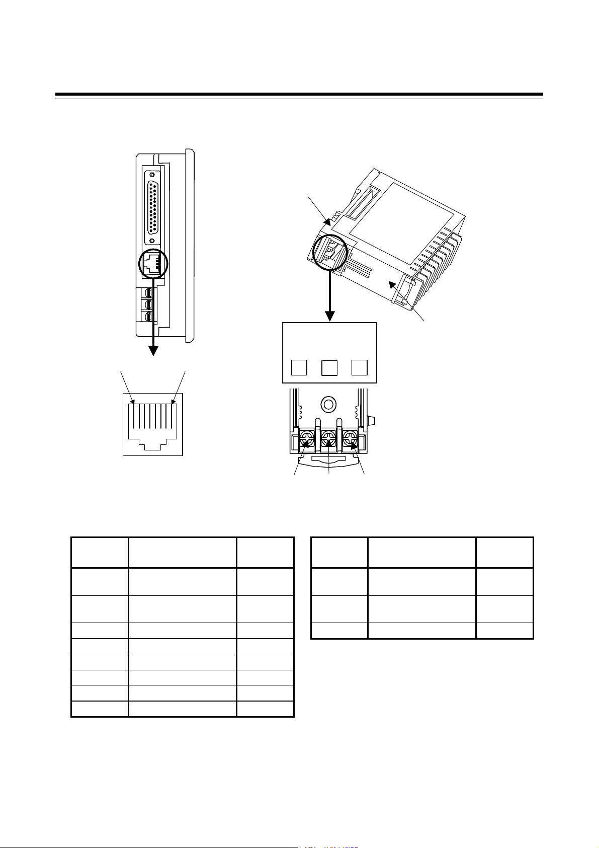
2.1.1 Connection to the SRZ
Use connection cable V6-MLT (Sold separately, Cable length: 3 m) to connect the OPC-V606E and the
SRZ.
Operation panel OPC-V606E
(Left side view)
Connect to
the [MJ1]
RS-485
Connection cable V6-MLT
Connect to the
communication terminals
SRZ module communication terminals
RS-485
T/R(A)
T/R(B)
4
SG
Module type controller SRZ
53
Base part of
the module
SRZ module
Connection cable V6-MLT
SD/RD (Green)
−
SD/RD (Black)
+
SG (Red)
Bottom of the module
For removing the base of the SRZ module, see the Z-TIO Instruction Manual (IMS01T01-E).
IMS01T08-E1 2-3
Page 14
2.1 Connections
Pin layout of connector (OPC-V606E)/Terminal configuration (SRZ)
Operation panel OPC-V606E (Left side view)
Base part of
the module
SRZ module
Bottom of the m odule
……………..
1
MJ1
RS-485
T/R(A)
8
T/R(B)
3
SG
53
4
Communication terminals
4
5
Signal details
OPC-V606E [MJ1] SRZ [Communication terminals]
Pin No. Signal name Symbol
1 RS-485
+SD/RD
send/receive data
2 RS-485
−SD/RD
send/receive data
3 Unused
4 Unused
Terminal
No.
Signal name Symbol
3 RS-485
send/receive data
4 RS-485
send/receive data
5 Signal ground SG
5 Signal ground SG
6 Signal ground SG
7 Unused
8 Unused
T/R (A)
T/R (B)
2-4 IMS01T08-E1
Page 15

Wiring contents
2.1 Connections
Module type controller SRZ
Operation panel OPC-V606E
+SD/RD
SD/RD
−
Unused
Unused
SG
SG
Unused
Unused
Modular connector
MJ1
Turns on a termination resistor
setting DIP switches (No. 6) of
OPC-V606E side modular
connector [MJ1].
Recommended modular connector
Modular connector for connect to operation panel OPC-V606E:
TM10P-88P (Manufactured by HIROSE ELECTRIC CO., LTD.)
For installation of termination resistor, see the 2.1.2 Installation of termination resistor
(P. 2-6).
1
2
3
4
5
6
7
8
Shielded twisted
Pair wire
Connectied by
the internal
communication
line
pair wire
R1: External termination
resistor (120 Ω 1/2 W)
Maximum number of connected SRZ module: 31 modules
Temperatur control module (Z-TIO): 1 to 16 modules
Digital I/O module (Z-DIO): 0 to 16 modules
R1
T/R (A)
3
4
T/R (B)
5
SG
3
4
5
T/R (A)
T/R (B)
SG
IMS01T08-E1 2-5
Page 16

2.1 Connections
2.1.2 Installation of termination resistor
Install terminating resistors to both ends of the RS-485 communication line.
Installation of termination resistor for SRZ
Mounting position
Connect a termination resistor between the communication terminals (No.3 and 4) of the module at the end
of the communication line from the host computer.
Termination resistor
(Example: 120 Ω 1/2 W)
T/R(A) T/R(B)
To operation panel OPC-V606E
When two or more module are connected
Module type controller SRZ
Internal communication line
(RS-485)
Operation
panel
OPC-V606E
RS-485
(Base)
34 5
Recommended tightening torque:
0.4 N・m (4 kgf・cm)
SG
Connect the termination
resistor to this module.
Termination
resistor
Continued on the next page.
2-6 IMS01T08-E1
Page 17

r
When two or more SRZ units are connected
Operation
panel
OPC-V606E
RS-485
RS-485
RS-485
Module type controller SRZ
Z-TIO module Z-DIO module
Internal communication line (RS-485)
Module type controller SRZ
Z-TIO module Z-DIO module
Internal communication line (RS-485)
Module type controller SRZ
Z-TIO module
Internal communication
line (RS-485)
Termination
resisto
Z-DIO module
Connect the termination
resistor to this module.
2.1 Connections
IMS01T08-E1 2-7
Page 18

2.1 Connections
Installation of termination resistor for operation panel OPC-V606E
Set the termination resistor of modular connector [MJ1] with DIP switches No. 6.
Operation panel OPC-V606E (Rear)
CN1
MJ1
+
24VDC
-
DIP switch
ON
1 2 3 4 5 6 7 8
Switch No.7 and 8 must be always OFF. Do not set to ON.
Termination resistor of modular connector [MJ1]
OFF:
If the OPC-V606E is other than a termination when connected to the MJ1 modular
connector using SRZ and RS-485.
ON:
If the OPC-V606E is a termination when connected to the MJ1 modular connector
using SRZ and RS-485.
Factory set value: ON
Switch No.1 to 5 must be always OFF. Do not set to ON.
2-8 IMS01T08-E1
Page 19

2. PREPARATIONS
2.2 Communication Setting
To prevent electric shock or instrument failure, always turn off the power
before setting the switch.
To prevent electric shock or instrument failure, never touch any section other
than those instructed in this manual.
WARNING
!
Set the communication parameter for communication between the operation panel OPC-V606E and the
SRZ.
2.2.1 Module address setting
When using two or more modules, set the desired address to each module.
Set the module address by address setting switches of front of module. For this setting, use a small blade
screwdriver.
To avoid problems or malfunction, do not duplicate an address on the same communication
line.
Set the module addresses in order from “0” without skipping any numbers. If a number is
skipped, “no response” will occur.
Setting of “Address
setting switch”
( ): Decimal number
RX/TX
Module type controller SRZ
0
1
(0)
(1)
Address setting switch
E
(14)F (15)
(2)
2
…
Setting range:
0 to F [0 to 15: Decimal numbers]
(Factory set value: 0)
D
(13)
(0)
0
1
…
(1)
(14)
E
[Temperature control module (Z-TIO)]
Set address number from the “0” sequentially.
The value obtained by adding “1” to the set
address corresponds to the address used
for the actual communication.
[Digital I/O module (Z-DIO)]
Set address number from the “0” sequentially.
The value obtained by adding “17” to the set
address corresponds to the
for the actual communication.
address used
Maximum number of connected SRZ module: 31 modules
• Temperatur control module (Z-TIO): 1 to 16 modules
• Digital I/O module (Z-DIO): 0 to 16 modules
IMS01T08-E1 2-9
Page 20

2.2 Communication Setting
Relation of module address and display channel number
Channel numbers displayed on the OPC-V606E operation panel screen are determined in order from the
“0” module address number.
[Example 1: When constructed unit with the temperature control module of 4-channel type.]
Temperature control module (Z-TIO-A: 4-channel type)
Module type controller SRZ
Address number
of module
Channel number
of module
The channel number
that is displayed on
the screen
Screen
CH3
CH3
CH4
CH4
0
CH1
CH1
CH2
CH2
CH3
CH7
CH4
CH8
1
CH1
CH5
CH2
CH6
…
…
…
CH3
CH63
CH64
15
CH4
CH61
CH1
CH2
CH62
The number of channels displayed on the screen is in accordance with the OPC-V606E initial
setting: “Number of modules set.” If “Number of modules set” is at “1” in the above system
configuration, no data on and after CH5 is displayed.
For details of number of module setting, see the 2.5 Set the Number of Connection Modules
(P. 2-18).
2-10 IMS01T08-E1
Page 21

2.2 Communication Setting
[Example 2: When constructed unit with the temperature control module of 2-channel type and
4-channel type.]
Module type controller SRZ
Address number
of module
Channel number
of module
The channel number
that is displayed on
the screen
Screen
Temperature control module
(Z-TIO-B: 2-channel type)
0
CH1
CH1
CH3
CH2
CH7
CH2
Temperature control module
(Z-TIO-A: 4-channel type)
…
…
…
CH4
CH8
1
CH1
CH2
CH5
CH6
CH3
CH63
15
CH4
CH61
CH64
CH1
CH2
CH62
When the temperature control
module of 2-channel type is
used, the display corresponding
to the CH3 and CH4 section
becomes blank.
IMS01T08-E1 2-11
Page 22

2.2 Communication Setting
p
2.2.2 Communication speed, data bit configuration and protocol setting
With the DIP switch which there is on the right side of SRZ module, select communication speed, data bit
configuration and protocol. Always make the same communication settings on the OPC-V606E and SRZ.
The data changes become valid when the power is turned on again or when changed to RUN with
“RUN/STOP transfer” of operation mode.
When two or more modules are connected on the same line, turn each switch in the DIP
switches of all of the modules to the same position. Otherwise the module may fail or
malfunction.
[Factory set value of operation panel OPC-V606E]
• Communication speed (baud rate) 19200 bps
• Data 8-bit, without parity, stop 1-bit
• Modbus protocol
See 2.2.3 Confirmation of communication parameter of the OPC-V606E side (P. 2-13).
SRZ module main frame
Z-TIO module
Z-DIO module
Right side view
[S
etting contents]
1 2 3 4 5 6 7 8
OFF ON OFF OFF ON ON OFF OFF
1 2 Communication speed
OFF OFF 4800 bps
ON OFF 9600 bps
OFF ON 19200 bps
ON ON 38400 bps
Factory set value: 19200 bps
3 4 5 Data bit configuration
OFF OFF OFF Data 7-bit, without parity, Stop 1-bit *
OFF OFF ON Data 7-bit, Even parity, Stop 1-bit *
OFF ON ON Data 7-bit, Odd parity, Stop 1-bit *
OFF OFF ON Data 8-bit, without parity, Stop 1-bit
OFF ON ON Data 8-bit, Even parity, Stop 1-bit
ON ON ON Data 8-bit, Odd parity, Stop 1-bit
* When the Modbus communication protocol is selected, this setting becomes invalid.
Factory set value: Data 8-bit, without parity, Stop 1-bit
6 7 Protocol
OFF OFF RKC communication
ON OFF Modbus
Factory set value: RKC communication
Switch No. 8: OFF fixed (Do not change this one)
DIP switch
1234567
8
OFF
Set to 19200 bps
Set to Modbus
ON
ON
Set to data 8-bit,
without parity and
sto
1-bit
2-12 IMS01T08-E1
Page 23

2.2 Communication Setting
2.2.3 Confirmation of communication parameter of the OPC-V606E side
The parameter for communication between the operation panel OPC-V606E and SRZ on the operation
panel side can be checked on the “Extension Prog. Info.” screen.
< Extension Prog. Info. screen >
Extension Prog. Info.
Temp. CTRL Drv
VER. 1.100
RKC SR-Mini/CB
Temp. CTRLComm. Param.
Signal level:
RS485
Baud Rate: 19200
Data Length: 8
Stop Bit: 1
Parity: None
Retry Time: 3
Time-out: 300msec
Send Delay: 6msec
Return Time: 10sec
Main Menu
Main Menu
Touching this key change to the “Main Menu”
screen.
Temperature control communication parameter
The parameter for communication between the
operation panel and SRZ is displayed but cannot
be set.
The parameter for communication on the OPC-V606E side is changed by the panel editor
V-SFTE. For the panel editor V-SFTE, please contact RKC sales office or the agent.
Operation procedures
1. Press and hold the [SYSTEM] switch, and press the [F5] switch at the same time.
“Main Menu” screen is displayed. The “Main Menu” screen can be changed on any screen.
SYSTEM switch
SYSTEM
F1
F2
F3
F4
Main Menu
F5
F5 switch
Continued on the next page.
IMS01T08-E1 2-13
Page 24

2.2 Communication Setting
Continued from the previous page.
2. Touch the [Extension] key. “Extension Prog. Info.” screen is displayed.
enu
Main M
Extension
Exte nsion
3. After the information is checked, touch the [Main Menu] key to call out the “Main Menu” screen.
Extension Prog. Info.
Extension Prog. Info.
Temp. CTRL Drv
VER. 1.100
Temp. CTRL Drv
RKC SR-Mini/CB
VER. 1.100
RKC SR-Mini/CB
Temp. CTRLComm. Param.
Main Men u
Main Menu
Signal level:
Temp. CTRLComm. Param .
RS485
Signal level:
Baud Rate: 19200
RS485
Data Length: 8
Baud Rate: 19200
Stop Bit: 1
Data Length: 8
Parity: None
Retry Time: 3
Stop Bit: 1
Time-out : 300msec
Parity: None
Send Delay: 6msec
Retry Time: 3
Return Time: 10sec
Time-out: 300ms ec
Send Delay: 6msec
Return Time: 10sec
Main Menu
4. Press the [SYSTEM] switch with the “Main Menu” screen being displayed. The menu is displayed at
the side of the function switch.
S
Y
SYSTEM
S
F1
M
O
D
F2
E
CT
F3
F4
Menu
F5
5. Press the [F1] switch with the menu being displayed.
Pressing the [F1] switch displays the “Opening” screen after an error is checked and then displays the
“TIO Monitor” screen.
S
Y
SYSTEM
S
F1
M
O
D
E
CT
F2
F3
The menu disappears after a certain lapse of time.
If it disappears, press the [SYSTEM] switch again.
F4
Menu
F5
2-14 IMS01T08-E1
Page 25

2.3 Start-up Procedures
Check prior to power on
Check the following items before turning on the power to the operation panel OPC-V606E.
communication setting of
Check the
mounting and wiring
Check the connections
Check the
termination resistor
Check the
SRZ
Confirms the mounting and wiring.
See the instruction manual of Hakko Electronics Co., Ltd.
Connections conform to 2.1 Connections (P. 2-2).
Termination resistor setting conforms to 2.1.2 Installation of
termination resistor (P. 2-6).
Communication setting conforms to 2.2 Communication Setting
(P. 2-9).
Power on
First, turn on the power for module type controller SRZ,
then for operation panel OPC-V606E.
Setting after power on
2. PREPARATIONS
Set the number of connection
Power on
Contrast adjustment
modules
Operations
If you changed the SRZ initial data in SRZ loader communication, turn off the power of the
OPC-V606E and then turn it back on (power reset). The initial data will be effective after
the power reset.
Adjust the contrast of the screen display.
For contrast adjustment, see the 2.4 Contrast Adjustment
(P. 2-16).
Set the number of the SRZ modules connected to an operation panel.
For the number of module connection, see the 2.5 Set the
Number of Connection Modules (P. 2-18).
IMS01T08-E1 2-15
Page 26

2. PREPARATIONS
2.4 Contrast Adjustment
The contrast adjustment can be set with the function switches.
Operation procedures
1. Press and hold the [SYSTEM] switch, and press the [F5] switch at the same time.
“Main Menu” screen is displayed. The “Main Menu” screen can be changed on any screen.
SYSTEM switch
SYSTEM
F1
F2
Main Menu
F3
F4
F5
F5 switch
Continued on the next page.
2-16 IMS01T08-E1
Page 27

2.4 Contrast Adjustment
Continued from the previous page.
2. Press the [SYSTEM] switch with the “Main Menu” screen being displayed. The menu is displayed at
the side of the function switch.
F1: Mode
Main menu mode ends.
S
Y
S
M
O
D
E
CT
CT
CT
B
K
L
T
SYSTEM
F1
F2
F3
F4
F5
F2: Contrast adjustment (dark)
This switch adjusts the contrast of LCD. When the [F2]
switch is pressed once, the LCD color becomes dark. If this
switch is held down for 1 second, the LCD color changes
rapidly into darkness.
F3: Contrast adjustment (intermediate)
This switch adjusts the contrast of LCD. When the [F3]
switch is pressed once, the LCD color becomes intermediate.
F4: Contrast adjustment (light)
This switch adjusts the contrast of LCD. When the [F4]
switch is pressed once, the LCD color becomes light. If this
switch is held down for 1 second, the LCD color changes
rapidly into lightness.
F5: Invalidity (Ignored)
Menu
3. Press the [F2] to [F4] switches with the menu being displayed. The contrast adjustment can be set.
4. Press the [F1] switch with the menu being displayed.
Pressing the [F1] switch displays the “Opening” screen after an error is checked and then displays the
“TIO Monitor” screen.
S
Y
SYSTEM
S
F1
M
O
D
E
CT
Menu
F2
F3
F4
F5
The menu disappears after a certain lapse of time.
If it disappears, press the [SYSTEM] switch again.
IMS01T08-E1
2-17
Page 28

2. PREPARATIONS
2.5 Set the Number of Connection Modules
The number of the module connection sets it after releasing an initial setting the key protection.
Operation procedures
1. Touch the [Menu] key on the “TIO Monitor” screen, to switch to the “Operation Menu” screen.
2. Touch the [Initial Setting] key on the “Operation Menu” screen, to switch to the “Password
confirmation” screen.
3. Enter the password “0000” and touch the [ENT] key.
If the password is correct, the screen will change to the “Initial Menu” screen.
The password in shipment becomes “0000.”
When changes the password, see the 3.10.16 Password set screen (P. 3-88).
Continued on the next page.
2-18 IMS01T08-E1
Page 29

2.5 Set the Number of Connection Modules
Continued from the previous page.
4. Touch the [Number of modules set] key on the “Initial Menu” screen, to switch to the “Number of
modules set” screen.
5. Set the number of the connection of the Z-TIO modules and Z-DIO modules.
Set the number of the SRZ modules connected to
an operation panel OPC-V606E.
Setting range:
Number of Z-TIO modules: 1 to 16 (Factory set value: 1)
Number of Z-DIO modules: 0 to 16 (Factory set value: 0)
Up to 31 modules including both Z-TIO module
and Z-DIO module.
6. When the number of connecting modules is changed, always reset the OPC-V606E in accordance
with any of the following procedures. The number of modules thus changed becomes valid after the
OPC-V606E is reset.
• Reset with power
Turn off the power once and then turn it on again.
• Reset with switch operations
1. Press and hold the [SYSTEM] switch, and press the [F5] switch at the same time.
2.
3. Press the [F1] switch with the menu being displayed.
IMS01T08-E1
“Main Menu” screen is displayed. The “Main Menu” screen can be changed on any screen.
Press the [SYSTEM] switch with the “Main Menu” screen being displayed. The menu is
displayed at the side of the function switch.
Pressing the [F1] switch displays the “Opening” screen after an error is checked and then
displays the “TIO Monitor” screen.
2-19
Page 30

MEMO
2-20 IMS01T08-E1
Page 31

SCREEN
DESCRIPTIONS
3.1 Screen Configuration........................................................................3-2
3.2 Basic Operations..............................................................................3-6
3.2.1 Data settings .............................................................................................3-6
3.2.2 Text editing.............................................................................................. 3-10
3.3 Start-up Screen ..............................................................................3-14
3.4 Operation Menu Screen .................................................................3-17
3.5 Monitor Screen...............................................................................3-19
3.6 Trend Graph Screen.......................................................................3-33
3.7 Setting Screen................................................................................3-36
3.8 Operation Mode Screen .................................................................3-48
3.9 DO Setting Screen .........................................................................3-54
3.10 Initial Setting Screen.....................................................................3-57
3.11 Screen Setting Examples When Using DIO..................................3-89
3.11.1 Example of using DI ..............................................................................3-89
3.11.2 Example of using DO.............................................................................3-94
IMS01T08-E1 3-1
Page 32

3. SCREEN DESCRIPTIONS
A
A
A
(
A
)
(
(
)
r
3.1 Screen Configuration
Power ON
utomatic
Check
Voltage drop of the battery
for SRAM cassette
P. 3-14
Operation
P. 3-18
Menu
utomatic
P.3-14
Opening
Error occurs
utomatic
P. 3-23
TIO Monitor
(PV/SV)
P. 3-25
TIO Alarm Monitor
E1/E2/E3/E4)
TIO Monitor
(MVH/MVC)
TIO Alarm Monitor
BO/HBA
DIO Monitor
P. 3-26
P. 3-33
CH Select Trend Graph
TIO Setting Menu
P. 3-38
For the screen list, see the TIO setting menu (P. 3-3).
Operation Mode
DO Setting Menu
P. 3-49
For the screen list, see the Operation mode menu (P. 3-3).
Menu
P. 3-54
For the screen list, see the DO setting menu (P. 3-3).
Configuration Monitor
Menu 1
Initial Menu
P. 3-27
Configuration Monito
Menu 2
P. 3-63
For the screen list, see the Initial menu (P. 3-4).
Always set the number of modules when the power was turned on for the first time is
started after the connectable number of modules changed. If no number of modules is set,
the screen may not be correctly displayed to cause malfunction. The number of modules is
set on the “Number of modules set” screen.
If you changed the SRZ initial data in SRZ loader communication, turn off the power of the
OPC-V606E and then turn it back on (power reset). The initial data will be effective after
the power reset.
P. 3-23
P. 3-25
P. 3-35
P. 3-30
P. 3-16
Warning
(Battery replacement)
P. 3-14
Error message
P. 3-24
TIO Monitor
CT/HB
For the screen list, see the
Configuration monitor menu
(P. 3-4).
3-2 IMS01T08-E1
Page 33

3.1 Screen Configuration
TIO setting menu
Screen name Page
Set value (SV) 3-44
Manual Output 3-44
Event Setting Menu Event 1 set value 3-44
Event 2 set value 3-44
Event 3 set value 3-44
Event 4 set value 3-44
PID Setting Menu Proportional band 3-45
Integral Time 3-45
Derivative Time 3-45
Proportional band [cool-side] 3-45
Integral Time [cool-side] 3-45
Derivative Time [cool-side] 3-45
Overlap/Deadband 3-45
Control response parameter 3-45
Other Setting 1 Menu HBA set value 3-46
Heater break determination point 3-46
Heater melting determination point 3-46
Proportional cycle time 3-46
Minimum ON/OFF time of proportioning cycle 3-46
Control loop break alarm (LBA) time 3-46
LBA deadband 3-46
Other Setting 2 Menu PV bias 3-47
PV digital filter 3-47
PV ratio 3-47
PV low input cut-off 3-47
Setting change rate limiter (up) 3-47
Setting change rate limiter (down) 3-47
Startup tuning (ST) ON/OFF 3-47
Communication switch for logic 3-47
Operation mode menu
Screen name Page
Operation Mode Menu Operation mode transfer 3-52
PID/AT transfer 3-52
Auto/Manual transfer 3-52
RUN/STOP transfer 3-52
Interlock release 3-52
Remote/Local transfer 3-52
DO setting menu
Screen name Page
DO Setting Menu DO RUN/STOP transfer 3-56
DO manual output 3-56
DO output distribution selection 3-56
IMS01T08-E1 3-3
Page 34

3.1 Screen Configuration
Configuration monitor menu
Screen name Page
Configuration Monitor Menu 1 Control action 3-28
Address of interacting modules 3-28
Channel selection of interacting modules 3-29
Selection switch of interacting modules 3-29
Configuration Monitor Menu 2 DO output assignment 1 3-31
DO output assignment 2 3-31
DO signal assignment module address 1 3-31
DO signal assignment module address 2 3-32
DI function assignment 3-32
Initial menu
Protection release is necessary to display each initial screen.
For details, see the 3.10.1 Releasing procedure of the initial setting key protect (P. 3-57).
Number of modules set 3-64
Clock set 3-65
Name Setting Menu Alarm Message Set 3-67
TIO CH name set 3-68
Screen Saver Set 3-69
TIO controller initial menu Input parameter menu Input type 3-73
Decimal point position 3-73
Input scale high 3-73
Input scale low 3-73
Display unit 3-73
Control parameter menu Control action 3-74
Control RUN/STOP holding setting 3-74
Event parameter menu Event 1 type 3-74
Event 1 channel setting 3-75
Event 1 hold action 3-75
Event 1 interlock 3-75
Event 1 differential gap 3-75
Event 1 delay timer 3-75
Force ON of Event 1 action 3-75
Event 2 type 3-74
Event 2 channel setting 3-75
Event 2 hold action 3-75
Event 2 interlock 3-75
Event 2 differential gap 3-75
Event 2 delay timer 3-75
Force ON of Event 2 action 3-75
Screen name
Page
Continued on the next page.
3-4 IMS01T08-E1
Page 35

3.1 Screen Configuration
Continued from the previous page.
TIO controller initial menu Event parameter menu Event 3 type 3-74
Event 3 channel setting 3-75
Event 3 hold action 3-75
Event 3 interlock 3-75
Event 3 differential gap 3-75
Event 3 delay timer 3-75
Force ON of Event 3 action 3-75
Event 4 type 3-74
Event 4 channel setting 3-75
Event 4 hold action 3-75
Event 4 interlock 3-75
Event 4 differential gap 3-75
Event 4 delay timer 3-75
Force ON of Event 4 action 3-75
Output parameter menu Output limiter (high) [heat-side] 3-76
Output limiter (low) [heat-side] 3-76
Output limiter (high) [cool-side] 3-76
Output limiter (low) [cool-side] 3-76
CT parameter menu CT ratio 3-76
CT assignment 3-76
Heater break alarm (HBA) type 3-76
Number of HBA delay times 3-76
Interacting parameter menu Address of interacting modules 3-77
Channel selection of interacting modules 3-77
Selection switch of interacting modules 3-77
ST parameter menu ST start condition 3-77
AT parameter menu AT bias 3-78
AT differential gap time 3-78
AT cycles 3-78
Output value with AT turned on 3-78
Output value with AT turned off 3-78
Communication parameter menu Interval time 3-78
Input error parameter menu Input error determination point (high) 3-79
Input error determination point (low) 3-79
Burnout direction 3-79
DIO controller initial menu DO output assignment 1 [DO1 to DO4] 3-84
DO output assignment 2 [DO5 to DO8] 3-84
DO signal assignment module address 1 [DO1 to DO4] 3-84
DO signal assignment module address 2 [DO5 to DO8] 3-84
DO energized/de-energized 3-85
Interval time 3-85
DI function assignment 3-85
Memory area setting signal 3-85
Password set Password set 3-88
Screen name
Page
IMS01T08-E1 3-5
Page 36

3. SCREEN DESCRIPTIONS
+/−
+/−
3.2 Basic Operations
3.2.1 Data settings
You directly touch the data setting or the part you want to change, the numeric keypad window appears on
the screen.
< Numeric keypad window >
Data editing section
CH
1
100.0
7 8 9
4 5 6
Close key
Close
CH
CLR
Data setting selection key
CLR key
1 2 3
ENT
0 .
ENT key
key
Data editing section: Edits the data. The cursor shows where data is input. The number of characters that
cab be edited in the data editing section depends on the number of characters that
can be input for the data.
Close key: Disappearing the numeric keypad window
Data setting selection key:
Used to select any one of the following data settings. Every time this key touched,
the data setting changes.
CH: Setting for each channel
The desired data is directly touched for its setting.
All CH: Setting for all channels
The same items related to all channels are simultaneously set to the
CLR key: Erases the input data. If you input the wrong number, touching this key.
ENT key: Enters the text displayed in the data editing section and closes the numeric keypad
window.
+/− key: The [+/−] key toggles the value between plus and minus. After inputting the
number, set the + or − with this key before touching the [ENT] key.
same numeric values.
The available setting differs depending on the setting item. If the setting
cannot be changed even when touched on the data setting selection key, that
setting cannot be used. In addition, there are some setting items in which no
data setting selection key is displayed.
3-6 IMS01T08-E1
Page 37

3.2 Basic Operations
+/−
+
Disappearing the numeric keypad window
If you accidentally touch a setting part that you do not need to change and the numeric keypad window
appears, either just press the [ENT] key without inputting a number or touch the top left section of the
numeric keypad window twice in a row to put out the numeric keypad window without changing the value.
Close
CH
1
100.0
7 8 9
CH
CLR
4 5 6
1 2 3
ENT
0 .
Setting for each channel
Example: When CH1 set value (SV) is change from 100 °C to 200 °C.
1. Touch the [TIO Setting] key on the “Operation Menu” screen, to switch to the “TIO Setting Menu”
screen.
2. Touch the [SV] key on the “TIO Setting Menu” screen, to switch to the “Setting: SV” screen.
3. From the “Setting: SV” screen, directly touch the part you want to setting (CH1 SV). The numeric
keypad window appears on the screen.
Numeric keypad window
Close
CH
1
100.0
7 8 9
CH
CLR
4 5 6
1 2 3
ENT
4. Touch the [2], [0], [0] key.
2 00
CH
1
200.0
0.
/−
IMS01T08-E1 3-7
Page 38

3.2 Basic Operations
5. Check that the data setting selection key is [CH].
CH
6. Touch the [ENT] key to enter the data. When the data is entered, the numeric keypad window
disappears.
Numeric keypad window
CH
1
200.0
7 8 9
Close
CH
CLR
4 5 6
1 2 3
ENT
0 .
If you input a number outside the valid range, when you touch the [ENT] key, the numeric
keypad window does disappear, but the value is not changed.
Setting for all channels (Batch setting)
Example: When all set value (SV) is change to 200 °C.
1. Touch the [TIO Setting] key on the “Operation Menu” screen, to switch to the “TIO Setting Menu”
screen.
2. Touch the [SV] key on the “TIO Setting Menu” screen, to switch to the “Setting: SV” screen.
3. From the “Setting: SV” screen, directly touch the part you want to setting (anywhere within the SV).
The numeric keypad window appears on the screen.
+/−
Numeric keypad window
Close
CH
100.0
7 8 9
1
CH
CLR
4 5 6
1 2 3
ENT
0.
3-8 IMS01T08-E1
+/−
Page 39

3.2 Basic Operations
4. Touch the [2], [0], [0] key.
2 00
CH
1
200.0
5. Touch the data setting selection key to change the display to the [All CH].
CH All CH
6. Touch the [ENT] key to enter the data. When the data is entered, the numeric keypad window
disappears.
Numeric keypad window
CH
1
200.0
7 8 9
Close
All CH
CLR
4 5 6
1 2 3
ENT
0 .
If you input a number outside the valid range, when you touch the [ENT] key, the numeric
keypad window does disappear, but the value is not changed.
+/−
IMS01T08-E1 3-9
Page 40

3.2 Basic Operations
z
Y
A
3.2.2 Text editing
The text editing window is used for setting names and messages. On a screen for inputting a name or
message, when you touch a section for text input, the text editing window appears.
<Text editing window>
Text editing section Editing type display
Half1 1
B C D E F G H I J
K L M N O P Q R S T
U V W X
ef
op
y
8 9
g
h i
q
r s t u v w x
0 1 2 3 4 5 6 7
Z a b c d
j
k l m n
Character
select keys
Prev Next
<< >>
DEL CLR
Text editing
BS SP
Enter
keys
Editing type display: Below is a list of the types of character editing. Editing type switches by [Prev] key,
[Next] key.
Half1: Alphabet, numeral
Half2: Symbols
Text editing section: Creates and edits the name or message. The cursor shows where characters are
input. The number of characters that can be edited in the text editing section
depends on the number of characters that can be input for the name or message.
Character selection keys:
Select the characters required for making and editing the name or message. When
you touch the character you want among those displayed, that character is
displayed at the cursor in the text editing section. The characters already at the
cursor are shifted to the rear. The contents displayed depend on the type of text
editing.
3-10 IMS01T08-E1
Page 41

3.2 Basic Operations
z
X
Y
A
Text editing keys
Prev key, Next key: Switch the type of characters required for making and editing the name or
message. These keys are used to switch the editing type display and the
character selection key display.
<< key: Moves the text editing section cursor to the left.
>> key: Moves the text editing section cursor to the right.
DEL key: Deletes the character at the cursor of the text editing section.
CLR key: Clears all the characters displayed in the text editing section.
BS key: Deletes the character to the left of the cursor of the text editing section.
SP key: Inserts a 1-byte space at the cursor of the text editing section.
Enter key: Enters the text displayed in the text editing section and closes the text editing
window.
Disappearing the text editing window
To stop text editing midway, touch the section at the top left of the text editing window twice in a row. The
text editing window disappears and the characters you were editing are thrown out.
Touch twice in a row
Harf1 1
B C D E F G H I J
K L M N O P Q R S T
U V W
e f
o p
y
8 9
Prev Next
g
h i
q
r s t u v w x
0 1 2 3 4 5 6 7
Z a b c d
j
k l m n
<< >>
BS SP
DEL CLR
Enter
IMS01T08-E1 3-11
Page 42

3.2 Basic Operations
<
<
y
0
p
q
x
g
j
A
Text editing
Example: Setting the name for TIO CH 1 (Temperature control channel 1) to “Tmp 1”
1. Calling the “TIO CH name set” screen.
For the details of calling procedure, see the 3.10.2 Calling procedure of the initial setting
screen (P. 3-59).
2. Touch the section for setting the TIO CH 1 name, the text editing window appears.
Half1 1
U V W X Y Z a b c d
e f
o
8 9
Text editing window
B C D E F G H I J
h i
r s t u v w
z
1 2 3 4 5 6 7
k l m n
>>
DEL CLRPrev Next
BS SP
Enter
3. Touch the [DEL] key or the [CLR] key to erase the text now displayed in the text editing section.
DEL CLR or
4. Touch the [T], [m], [p] keys to input “Tmp.”
T
p m
Tmp
5. Touch the [SP] key to insert a 1-byte space.
SP Tmp
6. Touch the [1] key to input “1.”
1
Tmp 1
3-12 IMS01T08-E1
Page 43

3.2 Basic Operations
漢
y
q
g
j
A
7. Touch the [Enter] key, after confirming “Tmp 1” inputted correctly in the text editing section. When
entered, the text editing window disappears and “1” is replaced with “Tmp 1.”
Half1
B C D E FG H I J
K L M N O PQ R S T
U V W X Y Z a b c d
e f
o p
8 9
Text editing window
Tmp 1
h i
r s t u v w x
z 0 1 2 3 4 5 6 7
<< >>
字
k l m n
DEL CLR
Prev Next BS SP
Enter
IMS01T08-E1 3-13
Page 44

3. SCREEN DESCRIPTIONS
t
b
3.3 Start-up Screen
When the power is turned on, first this screen is displayed, and then it is automatically changed to the next
screen (TIO Monitor screen).
<Check screen> <Opening screen>
Automatic
Automatic
To the TIO
Monitor screen
The operation panel checks whether there is an error in the SRZ configuration or hardware while the
start-up screen is displayed. If there is the error, the relevant “Error message” is displayed.
In addition, check a voltage drop of the SRAM cassette battery. If the battery voltage decreases, the
“Warning (battery replacement)” screen is displayed.
When an error occurs
<Error message screen>
Display of SRZ error
When an error occurs, the error contents are shown
in inversed display. The number of the abnormal
module is also displayed.
Display of error details of the operation panel itself
When an error occurs, the error contents are shown in
inversed display.
Back key
By touching this key, the previous screen jus
efore the error can be displayed. (If the error will
occur when the power was turned on, the screen
will return to the TIO Monitor screen.)
3-14 IMS01T08-E1
Page 45

3.3 Start-up Screen
Operation panel OPC-V606E error messages
Error messages Probable cause Solution
Parity Error
During communication, the data has
been wrongly written
Framing Error
During communication, the data has
been wrongly written
Over-Run
Problem with the taking-in of the
received data
No response from the SRZ
Breakage, wrong wiring, or imperfect
Mismatch of the setting data of
Wrong address setting
Wrong module configuration setting Configure the correct setting in the
Too much noise or surge might be
applied to the connecting cable with
SRZ.
Power supply defect of SRZ Confirm the power supply to the SRZ Time-Out
Wrong connection, no connection or
disconnection of the communication
cable
contact of the communication cable
communication speed and data bit
configuration with those of the SRZ
Investigate the wiring condition of the
connecting cable and whether there is a
noise generating source nearby, then
switch on the power again.
Confirm the connection method or
condition and connect correctly
Confirm the wiring or connector and
repair or replace the wrong one
Confirm the settings of SRZ and set
them correctly
“Number of modules set” screen of the
OPC-V606E initial settings.
SRZ error messages
Error messages Probable cause Solution
Adjust data error
• Adjustment data range is abnormal.
Data back-up error
• Back-up action is abnormal.
• Data write failure
• Response signal from A/D
converter is abnormal.
Custom data error
• There is an abnormality on logic
output data and it cannot execute.
The excessive noise, surge or strong
impact might be added to the SRZ
RAM is faulty
A/D converter is faulty A/D conversion
The excessive noise, surge or strong
impact might be added to the SRZ
The excessive noise, surge or strong
impact might be added to the SRZ
Replace the defective SRZ module
(The module whose FAIL green lamp
flashes)
IMS01T08-E1 3-15
Page 46

3.3 Start-up Screen
When a voltage drop of the SRAM cassette battery
< Warning (battery replacement) screen >
If the battery voltage for SRAM cassette has
dropped when the power is turned on, the
warning screen will be displayed.
supplied SRAM cassette, the data stored in
the SRAM cassette may be lost.
Please perform battery exchange promptly.
Replace battery: V6EM/RB
Back key
Touching this key changes to the “TIO
Monitor” screen.
If change to the “TIO Monitor” screen, no
“Warning (battery replacement)” screen is
displayed until the power is turned on again.
Data stored in the SRAM cassette:
Number of TIO modules
Number of DIO modules
Screen saver setting
Alarm message
TIO CH name
Trend graph (channel number, display scale high limit, display scale low limit)
Password
For the battery replacement, see the instruction manual of Hakko Electronics Co., Ltd.
Power not
3-16 IMS01T08-E1
Page 47

3. SCREEN DESCRIPTIONS
A
A
A
3.4 Operation Menu Screen
The operation menu screen allows the selection of each of the “Monitor,” “Setting,” “Operation Mode,”
and “Initial Set” screens.
3.4.1 Calling procedure of the operation menu screen
Warning
(Battery replacement)
Touch the
[Back] key
TIO Monitor
TIO Alarm Monitor
DIO Monitor
Trend Graph
TIO Setting Menu
Operation Mode Menu
DO Setting Menu
Configuration Monitor Menu
Voltage drop of
the battery for
SRAM cassette
Touch the [Menu] key
Power ON
utomatic
Check
utomatic
Opening
utomatic
TIO Monitor (PV/SV)
Touch the [Menu] key
Operation Menu
Touch the [Menu] key
Error occurs
Error message
Touch the
[Back] key
Initial Menu
IMS01T08-E1 3-17
Page 48

3.4 Operation Menu Screen
3.4.2 Operation menu screen
< Operation Menu screen >
Screen name
Displays the screen name.
Clock
Displays year (western calendar)/month/day
(day of the week) hour:minute. The clock can be
changed with the initial settings “Clock Set”
screen (P. 3-65).
Menu keys: Touching this key, screen can be selected.
TIO Monitor: “TIO Monitor (PV/SV)” screen
Alarm Monitor: “TIO Alarm Monitor (E1/E2/E3/E4)” screen
DIO Monitor: “DIO Monitor” screen
Trend Graph: “Trend Graph” screen
TIO Setting: “TIO Setting Menu” screen
Operation Mode: “Operation Mode Menu” screen
DO Setting: “DO Setting Menu” screen
Configuration Monitor:
“Configuration Monitor Menu” screen
Initial Setting: “Initial Menu” screen
This key is not displayed normally. Protection release is
necessary to display the key.
For details, see the 3.10.1 Releasing procedure of the initial
setting key protect (P. 3-57).
Menu keys
3-18 IMS01T08-E1
Page 49

3. SCREEN DESCRIPTIONS
(
(
)
A
(
A
)
T
r
g
[
y
[
]
3.5 Monitor Screen
Monitor screens are used to monitor the set value, measured value, control output value, alarm output, etc.
There are temperature control, alarm, DIO and configuration monitor screens.
3.5.1 Calling procedure of the monitor screen
[ ]: Key name.
Operation
menu
[TIO Monitor]
[Alarm Monitor]
[DIO Monitor]
[Configuration
Monitor]
* Touching the relevant key on the “Configuration Monitor Menu 1” screen or
“Configuration Monitor Menu 2” thus displayed calls up the setting screen.
For details, see the 3.5.6 Configuration monitor menu 1 screen (P. 3-27)
or 3.5.7 Configuration monitor menu 2 screen (P. 3-30).
Power ON
utomatic
TIO Monitor
PV/SV)
TIO Alarm Monitor
(E1/E2/E3/E4)
DIO Monitor
Configuration
Monitor Menu 1
*
*
interacting modules
*
Channel selection of
interacting modules
*
Selection switch of
interactin
Screen transfer:
TIO Monitor
MVH/MVC
Screen transfer: Touch the [Para.] key.
IO Alarm Monito
(BO/HBA)
Screen transfer: Touch the [Para.] key.
[DIO module]
Configuration
Monitor Menu 2
TIO module
Control action
Address of
modules
Touch the [Para] key
TIO Monitor
CT/HB
*
*
*
*
*
DO output
assignment 1
DO output
assignment 2
DO signal assignment
module address 1
DO signal assignment
module address 2
DI function
assignment
Screen transfer:
Touch the
Para] ke
IMS01T08-E1 3-19
Page 50

3.5 Monitor Screen
(
(
)
(
A
)
Touching the [Setting] key on the TIO monitor screen displays the respective setting screen. In
addition, touching the [Monitor] key on the setting screen displays the respective TIO monitor
screen.
TIO Monitor
TIO Monitor
MVH/MVC
TIO Monitor
PV/SV)
CT/HB
Setting screenMonitor screen
[Monitor]
Set value (SV)
[Setting]
[Monitor]
Manual Output
[Setting]
[Monitor]
[Setting]
HBA set value
3-20 IMS01T08-E1
Page 51

3.5.2 Basic configuration of monitor screen
The basic configuration of each monitor screen is as shown below.
On a temperature control 2-channel type Z-TIO module, the CH3 and CH4 displays are blank.
Example: TIO Monitor screen
Screen name
Engineering unit
Engineering unit can be
changed.
3.5 Monitor Screen
Clock
year/month/day (day of the week) hour : minute
Clock can be changed.
Monitor
item
Message
Alarm message can be changed.
Function keys
Channel name
Cannel name can be changed.
Screen name: Displays the screen name.
Engineering unit: Displays the engineering unit. The engineering unit (°C/°F) can be changed with
the TIO controller initialize “Display unit” screen (P. 3-73).
Clock: Displays year/month/day (day of the week) hour : minute. The clock can be
changed with the initial menu “Clock set” screen (P. 3-65).
Monitor item: Displays the item and data. Details of display varies depending on the each monitor
screen.
For the details of display, see the 3.5.3 TIO monitor screen (P. 3-23),
3.5.4 TIO alarm monitor screen (P. 3-25), 3.5.5 DIO monitor screen (P. 3-26),
3.5.6 Configuration monitor menu 1 screen (P. 3-27) and
3.5.7 Configuration monitor menu 2 screen (P. 3-30).
Channel name: Displays the TIO channel name. The channel name can be changed with the
initialize “TIO CH name set” screen (P. 3-68).
IMS01T08-E1 3-21
Page 52

3.5 Monitor Screen
Message: The alarm message is displayed at temperature rise completion or alarm occurrence.
Touching the message display area when an alarm occurs changes to the alarm
monitoring screen. Alarm occurring channel Nos. can be checked.
Alarm message list (Factory set value)
Item Message Priority order
BO: Burnout Burnout alarm is “ON” High
HBA: Heater break alarm Heater break alarm is “ON”
E1: Event 1 Event 1 alarm is “ON”
E2: Event 2 Event 2 alarm is “ON”
E3: Event 3 Event 3 alarm is “ON”
E4: Event 4 Event 4 alarm is “ON”
Temp.rise Temperature rise completion Low
The message of the burnout, heater break alarm, Event 1 alarm, Event 2
alarm, Event 3 alarm, Event 4 alarm and Temperature rise completion is
displayed if the relevant alarm occurs in any of the using channels. If more
than one type of alarm occurs simultaneously, the message corresponding
to the above item with higher priority is displayed. For example, if the
burnout and Event 1 alarm occur simultaneously, the burnout alarm
message is displayed.
The alarm message can be changed with the initialize “Alarm Message
Set” screen (P. 3-67).
Function keys: These key switches are assigned to match the contents of the screen.
Menu: Touching this key changes to the “Operation Menu” screen.
Setting: Touching this key changes from the monitor screen to the setting screen.
Item whose settings can be changed:
Set value (SV), manual output value (MVH), heater break alarm (HBA)
Prev.: Touching this key the display to the screen for the channel (CH) before the current
one. If there is no channel to be selected, the [Prev.] key becomes invalid.
Next: Touching this key the display to the screen for the channel (CH) after the current
one. If there is no channel to be selected, the [Next] key becomes invalid.
Para.: Every time this key is touched, the monitor screen changes. There is no this key on
the “DIO Monitor” screen.
3-22 IMS01T08-E1
Page 53

3.5 Monitor Screen
d
3.5.3 TIO monitor screen
There are PV/SV (Temperature measured value/temperature set value), MVH/MVC (Heat-side/cool-side
manipulated output value) and CT/HBA (Current transformer input measured value/heater break alarm set
value) in the TIO monitor screen. Changes the screen by touching [Para.] key.
For the function keys and other items, see the 3.5.2 Basic configuration of monitor screen (P. 3-21).
TIO monitor (PV/SV)
CH: Displays the TIO channel name.
PV: Displays the temperature measured value (PV).
Display range:
Input scale low to input scale high
SV: Displays the temperature set value (SV).
Display range:
Setting limit (low) to setting limit (high)
Touching [Setting] key changes to the “Setting: SV”
screen.
TIO monitor (MVH/MVC)
CH: Displays the TIO channel name.
MVH: Displays the heat-side manipulated output value.
Display range: −5.0 to +105.0 %
MVC: Displays the cool-side manipulated output value.
Display range: −5.0 to +105.0 %
Heating control makes the display blank.
Touching [Setting] key changes to the “Setting: Manual
Output” screen.
In heat/cool PID control, the displays of even-numbere
channels are blank.
IMS01T08-E1 3-23
Page 54

3.5 Monitor Screen
t
TIO monitor (CT/HBA)
CH: Displays the TIO channel name.
CT: Displays the current transformer (CT) inpu
measured value.
Display range: 0.0 to 100.0 A
(CTL-12-S56-10L-N) or
0.0 to 30.0 A (CTL-6-P-N)
HBA: Displays the heater break alarm set value
corresponding to current transformer (CT)
input.
Display range: 0.0 to 100.0 A
(CTL-12-S56-10L-N) or
0.0 to 30.0 A (CTL-6-P-N)
Touching [Setting] key changes to the “Setting: HBA
set value” screen.
3-24 IMS01T08-E1
Page 55

3.5 Monitor Screen
3.5.4 TIO alarm monitor screen
There are E1/E2/E3/E4 (Event status) and BO/HBA (Burnout/heater break alarm status) screens in the TIO
alarm monitor screen. Changes the screen by touching [Para.] key.
For the function keys and other items, see the 3.5.2 Basic configuration of monitor screen (P. 3-21).
TIO alarm monitor (E1/E2/E3/E4)
CH: Displays the TIO channel name.
E1: Displays the event 1 status.
Alarm occurrence: Flashes the “”
E2: Displays the event 2 status.
Alarm occurrence: Flashes the “”
E3: Displays the event 3 status.
Alarm occurrence: Flashes the “”
E4: Displays the event 4 status.
Alarm occurrence: Flashes the “”
TIO alarm monitor (BO/HBA)
CH: Displays the TIO channel name.
BO: Displays the burnout status.
Burnout occurrence: Flashes the “”
HBA: Displays the heater break alarm status.
Alarm occurrence: Flashes the “”
IMS01T08-E1 3-25
Page 56

3.5 Monitor Screen
3.5.5 DIO monitor screen
For the function keys and other items, see the 3.5.2 Basic configuration of monitor screen (P. 3-21).
CH: Displays the DIO channel number of Z-DIO module.
DI: Displays the contact status of digital input.
Contact closed status: Displays the “”
Contact open status: Displays the “”
DO: Displays the contact status of digital output.
Output ON: Displays the “”
Output OFF: Displays the “”
3-26 IMS01T08-E1
Page 57

3.5 Monitor Screen
3.5.6 Configuration monitor menu 1 screen
There are Control action, Address of interacting module, Cannel selection of interacting module and
Selection switch of interacting module screen in the Configuration monitor menu 1 screen. Changes the
screen by touching [Para.] key.
For the function keys and other items, see the 3.5.2 Basic configuration of monitor screen (P. 3-21).
< Configuration Monitor Menu 1 screen >
Screen name
Displays the screen name.
Displays the number of
connection modules.
Screen select keys
TIO module: Displays the number of Z-TIO modules connected to the OPC-V606E.
DIO module: Displays the number of Z-DIO modules connected to the OPC-V606E.
The number of modules displayed on the screen depends on the “Number of modules set” in
the initial settings.
For the number of module connection, see the 2.5 Set the Number of Connection Modules (P. 2-18).
Screen select keys: Touching this key, screen can be selected.
Control action: “Control action” screen
Address of interacting modules:
“Address of interacting modules” screen
Channel selection of interacting modules:
“Channel selection of interacting modules” screen
Selection switch of interacting modules:
“Selection switch of interacting modules” screen
Menu key: Touching this key changes to the “Operation Menu” screen.
DIO module: Touching this key changes to the “Configuration Monitor Menu 2” screen.
IMS01T08-E1 3-27
Page 58

3.5 Monitor Screen
Control action
Address of interacting modules
CH: Displays the TIO channel name.
Action: Displays the control action.
0: Brilliant II PID control (Direct action)
1: Brilliant II PID control (Reverse action)
2: Brilliant II Heat/Cool PID control
[Water cooling type]
3: Brilliant II Heat/Cool PID control
[Air cooling type]
4: Brilliant II Heat/Cool PID control
[Cooling gain linear type]
5: Position proportioning control
Odd channel: 0 to 5
Even channel *: 0 or 1
* In heat/cool control and position proportioning control,
control action is not performed. Only monitor and event
action is performed.
CH: Displays the TIO channel name.
Address:
Displays the module address number of the
module that specifies the channel which is to
interact at the Z-TIO module.
Display range:
−1: Interact with its own module
address
0 to 99: Interact with the addresses of other
modules
For Z-TIO module:
Displays the number that is set in the address
setting switch (0 to F) as a decimal number
(0 to 15).
For Z-DIO module:
Displays the number that is set in the address
setting switch (0 to F) as a decimal number
(0 to 15) with “16” added.
3-28 IMS01T08-E1
Page 59

Channel selection of interacting modules
Selection switch of interacting modules
3.5 Monitor Screen
CH: Displays the TIO channel name.
Channel: Displays the channel of interacting modules.
Display range: 1 to 99
CH: Displays the TIO channel name.
Switch: Displays the selection switch of interacting
modules.
Bit image: 0000000
bit 6··········· bit 0
Bit data
b0: Memory area number
b1: Operation mode
b2: Auto/Manual
b3: Remote/Local
b4: EDS start signal
b5: Interlock release
b6: Suspension of area soak time
b7 to b15: Unused
Data 0: No interaction
1: Interact with other channels
IMS01T08-E1 3-29
Page 60

3.5 Monitor Screen
3.5.7 Configuration monitor menu 2 screen
There are DO output assignment 1, DO output assignment 2, DO signal assignment Module address 1, DO
signal assignment Module address 2 and DI function assignment screen in the Configuration monitor menu
2 screen. Changes the screen by touching [Para.] key.
For the function keys and other items, see the 3.5.2 Basic configuration of monitor screen (P. 3-21).
< Configuration Monitor Menu 2 screen >
Screen name
Displays the screen name.
Displays the number of
connection modules.
Screen select keys
TIO module: Displays the number of Z-TIO modules connected to the OPC-V606E.
DIO module: Displays the number of Z-DIO modules connected to the OPC-V606E.
The number of modules displayed on the screen depends on the “Number of modules set” in the
initial settings.
For the number of module connection, see the 2.5 Set the Number of Connection Modules (P. 2-18).
Screen select keys: Touching this key, screen can be selected.
DO output assignment 1: “DO output assignment 1” screen
DO output assignment 2: “DO output assignment 2” screen
DO signal assign. module address 1:
“DO signal assignment module address 1” screen
DO signal assign. module address 2:
“DO signal assignment module address 2” screen
DI function assignment: “DI function assignment” screen
Menu key: Touching this key changes to the “Operation Menu” screen.
TIO module: Touching this key changes to the “Configuration Monitor Menu 1” screen.
3-30 IMS01T08-E1
Page 61

d
d
DO output assignment 1 [DO1 to DO4]
DO output assignment 2 [DO5 to DO8]
3.5 Monitor Screen
Module: Displays the module number.
Assignment:
Displays the DO output assignment 1
(DO1 to DO4).
Display range: 0 to 13
See the DO assignment code table (P. 3-86).
Module: Displays the module number.
Assignment:
Displays the DO output assignment 2
(DO5 to DO8).
Display range: 0 to 13
See the DO assignment code table (P. 3-86).
DO signal assignment Module address 1 [DO1 to DO4]
Module: Displays the module number.
Address: Displays the module address number of the
module used for the DO signal (DO1 to DO4)
selected in the DO output assignment.
Display range:
When “−1” is selected, all of the signals of the
same type (except temperature rise completion an
DO manual output value) are OR-operated an
produced as outputs from DO.
−1, 0 to 99
For Z-TIO module:
Displays the number that is set in the address
IMS01T08-E1 3-31
setting switch (0 to F) as a decimal number
(0 to 15).
For Z-DIO module:
Displays the number that is set in the address
setting switch (0 to F) as a decimal number
(0 to 15) with “16” added.
Page 62

3.5 Monitor Screen
d
d
DO signal assignment Module address 2 [DO5 to DO8]
Module: Displays the module number.
Address: Displays the module address number of the
module used for the DO signal (DO5 to DO8)
selected in the DO output assignment.
Display range:
When “−1” is selected, all of the signals of the
same type (except temperature rise completion an
DO manual output value) are OR-operated an
produced as outputs from DO.
For Z-TIO module:
Displays the number that is set in the address
setting switch (0 to F) as a decimal number
(0 to 15).
For Z-DIO module:
Displays the number that is set in the address
setting switch (0 to F) as a decimal number
(0 to 15) with “16” added.
DI function assignment
−1, 0 to 99
Module: Displays the module number.
Address: Displays the DI function assignment.
Display range: 0 to 29
See the DI assignment code table (P. 3-87).
3-32 IMS01T08-E1
Page 63

3. SCREEN DESCRIPTIONS
g
3.6 Trend Graph Screen
As trend graph screens, both trend graph screens to show trend graphs and channel selection screens to
conduct the setting necessary for displaying trend graphs are available.
3.6.1 Calling procedure of the trend graph screen
Operation
Menu
[Trend Graph]
[Menu]
[Setting]
CH Select Trend Graph
[Back]
[ ]: Key name.
3.6.2 Trend graph screen
The trend graph screen is for displaying temperature measured values and temperature set values in trend
graphs at a sampling period of 10 seconds. Up to 5 channels can be displayed.
1 channel/screen (number of screen: 5)
< Trend graph screen >
Display scale
high value
Sampling time
Trend data
Temperature set value
Display scale
low value
CH
TIO channel number of
the trend recording
PV
Temperature measured
value of the trend
recordin
Menu key
To the “Operation Menu”
screen
Monitor key
To the “TIO monitor (PV/SV)” screen
Setting key
To the “CH Select” screen
Trend data
Temperature measured
value
Count
Number of data
samplings
Trend graph operation
keys
Next key
To the “Trend Graph 2” screen
Reset key
Erase trend file data
Return key
Selection status is canceled
IMS01T08-E1 3-33
Page 64

3.6 Trend Graph Screen
Sampling time: Displays the final sampling time or the time that the selected trend data was sampled.
Trend data: Displays 50 data in a time-based sequence from among 2730 data in the trend file.
: Temperature measured value
: Temperature set value
Count: Displays what number of data samplings have been made on the selected trend data or
the total count of data samplings in the left lower portion on each trend graph.
Display range: 1 to 2730
If the total number of sampling data points exceeds 2730, a display of
2730 remains unchanged and older data is erased in order.
Sampling starts at the same time that the power is turned on. In addition, all
trend data is erased by turn OFF the power.
CH: The TIO channel number during trend recording is displayed. Any channel whose trend
recording is made is selected on the “CH Select” screen (P. 3-35).
PV: The temperature measured value during trend recording is displayed.
Menu key: Touching this key changes to the “Operation Menu” screen.
Monitor key: Touching this key changes to the “TIO Monitor (PV/SV)” screen.
Setting key: Touching this key changes to the “CH Select” screen.
Reset key: Sampling starts at the same time that the power is turned on and old data exceeding 2730
items are erased in sequence. Touch the [Reset] key when you want to erase this trend
file data. The [Reset] key touched it once, reversed display makes. When touched twice
within 2 seconds, the trend file is cleared. Reset is performed all at once for an 5 point
portion of the data file for that sampling period. Also sampling restarts right away after
being cleared. However if the [Reset] key is not touched again within 2 seconds,
operation is aborted and returns to former status.
Next key: Every time this key is touched, the trend graph number changes.
< Trend graph operation >
In the trend graph screen, the latest 50 sampled data are displayed on the right. The screen is automatically
updated for the sampling cycle. (10 seconds) The total data count (maximum of 2730) is displayed in the
“Count” column and the latest sampling time is displayed in the “Time” column.
Use the 4 keys [], [], [] and [] to scroll to view data that cannot all be shown at once on one
screen. Touch any of the [], [], [] or [] keys to select a trend data in the center of the screen
(draws a dotted line) and the [Return] key starts to flash. Now you can use the [], [], [] and []
keys to display the data zone you want on the graph and view that data and time. Selection is canceled by
touching the [Return] key.
key: Touching this key move the selected vertical trend dot line by one increment to an old
trend.
key: Touching this key move the selected vertical trend dot line by one increment to a new
trend.
key: Touching this key, scroll the selected vertical trend dot line in one page (50 data)
increments to an old trend and displays it.
key: Touching this key, scroll the selected vertical trend dot line in one page (50 data)
increments to a new trend and displays it.
Return key: Touch the flashing [Return] key in selection status to return to the latest trend sampling
display. Selection status is then canceled and the [Return] key stops flashing.
In selection status, the “Count” column displays the serial count of the selected data. The
sampling time of the selected data is shown in the “Time” column.
3-34 IMS01T08-E1
Page 65

3.6 Trend Graph Screen
3.6.3 CH select screen
This screen select the channel of carrying out the trend record. When displaying data as the trend graph, set
the scale high and scale low limit values.
< CH Select screen >
Back key
To the “Trend Graph” screen
No: Displays the trend graph number.
CH: Set the TIO channel number to record the trend data.
Setting range: 0 to 64 CH (0: Unused)
Factory set value: 0
PV: Displays the temperature measured value (PV).
Display range: Input scale low to input scale high
SV: Displays the temperature set value (SV).
Display range: Setting limit (low) to setting limit (high)
SCALE MAX: Set display scale high value becoming vertical line of graph.
Setting range: −30000 to +30000 (No decimal place)
−3000.0 to +3000.0 (One decimal place)
−300.00 to +300.00 (Two decimal places)
−30.000 to +30.000 (Three decimal places)
−3.0000 to +3.0000 (Four decimal places)
The position of the decimal point varies depending on the selected
TIO channel.
Factory set value: 0
SCALE MIN: Set display scale low value becoming vertical line of graph.
Setting range: −30000 to +30000 (No decimal place)
−3000.0 to +3000.0 (One decimal place)
−300.00 to +300.00 (Two decimal places)
−30.000 to +30.000 (Three decimal places)
−3.0000 to +3.0000 (Four decimal places)
The position of the decimal point varies depending on the selected
TIO channel.
Factory set value: 0
Back key: Touching this key changes to the “Trend Graph” screen.
IMS01T08-E1 3-35
Page 66

3. SCREEN DESCRIPTIONS
3.7 Setting Screen
The setting screen is used to set the temperature set value, manual output value, event set value, PID set
value or control related set values.
3.7.1 Calling procedure of the setting screen
Operation
Menu
[TIO Setting]
TIO Setting
Menu
[SV]
[MV]
[Event]
[PID]
A
[ ]: Key name.
Set value (SV)
Manual Output
Relevant
Event Setting
Menu
* Touching the relevant key on the “Event
Setting Menu” screen thus displayed calls
up the setting screen. For details, see the
3.7.3 Event setting menu screen
(P. 3-39).
PID Setting Menu
* Touching the relevant key on the “PID
Setting Menu” screen thus displayed calls
up the setting screen. For details, see the
3.7.4 PID setting menu screen (P. 3-40).
key *
Relevant
key *
Event 1 set value Event 3 set value
Event 2 set value
Screen transfer: Touch the [Para.] key.
Proportional Band
Integral Time
Derivative Time
Proportional Band
[cool-side]
Screen transfer: Touch the [Para.] key.
Event 4 set value
Integral Time
[cool-side]
Derivative Time
[cool-side]
Overlap/Deadband
Control response
parameter
Continued on the next page.
3-36 IMS01T08-E1
Page 67

d
r
d
(
(
)
(
A
)
Continued from the previous page.
A
[Other Setting 1]
* Touching the relevant key on the “Other
Setting Menu 1” screen thus displaye
calls up the setting screen. For details, see
the 3.7.5 Other Setting menu 2 screen
(P. 3-41).
Other Setting
Menu 1
[Other Setting 2]
* Touching the relevant key on the “Othe
Setting Menu 2” screen thus displaye
calls up the setting screen. For details, see
the 3.7.6 Other setting menu 1 screen
(P. 3-42).
Other Setting
Menu 2
Touching the [Setting] key on the monitor screen displays the respective setting screen. In
addition, touching the [Monitor] key on the setting screen displays the respective monitor screen.
Monitor screen
TIO Monitor
PV/SV)
TIO Monitor
MVH/MVC
TIO Monitor
CT/HB
[Monitor]
[Setting]
[Monitor]
[Setting]
[Monitor]
[Setting]
Relevant
key *
Relevant
key *
Setting screen
Set value (SV)
Manual Output
HBA set value
HBA set value
Heater beak
determination point
Heater melting
determination point
Proportional cycle
time
PV bias
PV digital filter
PV ratio
PV low input cut-off
Screen transfer: Touch the [Para.] key.
3.7 Setting Screen
Minimum ON/OFF
time
LBA time
LBA deadband
Screen transfer:
Touch the [Para.] key.
Setting change rate
limiter (up)
Setting change rate
limiter (down)
Startup tuning
ON/OFF
Communication
switch
IMS01T08-E1 3-37
Page 68

3.7 Setting Screen
3.7.2 TIO setting menu screen
The TIO setting menu screen is for selecting setting items relating to the control.
< TIO Setting Menu screen >
Screen name
Displays the screen name.
Clock
Displays year (western calendar)/month/day (day of
the week) hour : minute. The clock can be changed
with the initial settings “Clock set” screen (P. 3-65).
Screen select keys
Screen select keys: Touching this key, screen can be selected.
SV: “Setting: SV” screen
MV: “Setting: Manual Output” screen
Event: “Event Setting Menu” screen
PID: “PID Setting Menu” screen
Other Setting 1: “Other Setting 1 Menu” screen
Other Setting 2: “Other Setting 2 Menu” screen
Menu key: Touching this key changes to the “Operation Menu” screen.
3-38 IMS01T08-E1
Page 69

3.7.3 Event setting menu screen
The event setting menu screen is for selecting setting items relating to the event.
< Event Setting Menu screen >
Screen name
Displays the screen name.
Clock
Displays year (western calendar)/month/day (day of
the week) hour : minute. The clock can be changed
with the initial settings “Clock set” screen (P. 3-65).
3.7 Setting Screen
Screen select keys
Screen select keys: Touching this key, screen can be selected.
Event 1 set value: “Setting: Event 1 set value” screen
Event 2 set value: “Setting: Event 2 set value” screen
Event 3 set value: “Setting: Event 3 set value” screen
Event 4 set value: “Setting: Event 4 set value” screen
Menu key: Touching this key changes to the “TIO Setting Menu” screen.
IMS01T08-E1 3-39
Page 70

3.7 Setting Screen
3.7.4 PID setting menu screen
The PID setting menu screen is for selecting setting items relating to the PID.
< PID Setting Menu screen >
Screen name
Displays the screen name.
Clock
Displays year (western calendar)/month/day (day of
the week) hour : minute. The clock can be changed
with the initial settings “Clock set” screen (P. 3-65).
Screen select keys
Screen select keys: Touching this key, screen can be selected.
Prop. band [heat-side]: “Setting: Propotional band [heat-side]” screen
Integral time: “Setting: Integral Time” screen
Derivative time: “Setting: Derivative Time” screen
Prop. band [cool-side]: “Setting: Propotional Band [cool-side]” screen
Integral time [cool-side]: “Setting: Integral Time [cool-side]” screen
Derivative time[cool-side] : “Setting: Derivative Time [cool-side]” screen
Overlap/Deadband: “Setting: Overlap/Deadband” screen
Control response: “Setting: Control response parameter” screen
Menu key: Touching this key changes to the “TIO Setting Menu” screen.
3-40 IMS01T08-E1
Page 71

3.7.5 Other setting 1 menu screen
The other setting 1 menu screen is for selecting setting items relating to the control.
< Other Setting 1 Menu screen >
Screen name
Displays the screen name.
Clock
Displays year (western calendar)/month/day (day of
the week) hour : minute. The clock can be changed
with the initial settings “Clock set” screen (P. 3-65).
3.7 Setting Screen
Screen select keys
Screen select keys: Touching this key, screen can be selected.
HBA set value: “Setting: HBA set value” screen
Heater break determination:
“Setting: Heater break determination point” screen
Heater melting determination:
“Setting: Heater melting determination point” screen
Proportional cycle time:
“Setting: Proportional cycle time” screen
Minimum ON/OFF time of prop.:
“Setting: Minimum ON/OFF time of proportioning cycle” screen
LBA time: “Setting: LBA time” screen
LBA deadband: “Setting: LBA deadband” screen
Menu key: Touching this key changes to the “TIO Setting Menu” screen.
IMS01T08-E1 3-41
Page 72

3.7 Setting Screen
3.7.6 Other setting 2 menu screen
The other setting 2 menu screen is for selecting setting items relating to the control.
< Other Setting 2 Menu screen >
Screen name
Displays the screen name.
Clock
Displays year (western calendar)/month/day (day of
the week) hour : minute. The clock can be changed
with the initial settings “Clock set” screen (P. 3-65).
Screen select keys
Screen select keys: Touching this key, screen can be selected.
PV bias: “Setting: PV bias” screen
PV digital filter: “Setting: PV digital filter” screen
PV ratio: “Setting: PV ratio” screen
PV low input cut-off: “Setting: PV low input cut-off” screen
Setting change rate limt. (up):
“Setting: Setting change rate limiter (up)” screen
Setting change rate limt. (down):
“Setting: Setting change rate limiter (down)” screen
Startup tuning: “Setting: Startup tuning (ST)” screen
Communication switch for logic:
“Setting: Communication switch for logic” screen
Menu key: Touching this key changes to the “TIO Setting Menu” screen.
3-42 IMS01T08-E1
Page 73

3.7.7 Basic configuration of setting screen
The basic configuration of each setting screen is as shown below.
On a temperature control 2-channel type Z-TIO module, the CH3 and CH4 displays are blank.
Example: HBA set value screen
Screen name
Engineering unit
3.7 Setting Screen
Setting item
Function keys
Channel name
Channel name can be changed.
Screen name: Displays the screen name.
Engineering unit: Displays the engineering unit.
Setting item: Displays the item and data. Details of display varies depending on the each setting
screen.
For the details of setting, see the 3.7.8 Setting item list (P. 3-44).
Channel name: Displays the TIO channel name. The channel name can be changed with the
initialize “TIO CH name set” screen (P. 3-68).
Function keys: These key switches are assigned to match the contents of the screen.
Menu: Touching this key changes to the “TIO Setting Menu” “Event Setting Menu” screen,
“PID Setting Menu” screen, “Other Setting 1 Menu” screen or “Other Setting 2
Menu” screen.
Monitor: Touching this key changes from the settings screen to the monitor screen.
Prev.: Touching this key the display to the screen for the channel (CH) before the current
one. If there is no channel to be selected, the [Prev.] key becomes invalid.
Next: Touching this key the display to the screen for the channel (CH) after the current
one. If there is no channel to be selected, the [Next] key becomes invalid.
Para.: Every time this key is touched, the setting screen (setting item) changes. There is
no this key on the “Set value (SV)” screen and “Manual Output” screen.
IMS01T08-E1 3-43
Page 74

3.7 Setting Screen
yp
3.7.8 Setting item list
Some items may not be displayed depending on the specification.
Each setting item is selected by touching the [Para.] key on the relevant screen.
For the setting procedure, see the 3.2.1 Data settings (P. 3-6).
For the function keys and other items, see the 3.7.7 Basic configuration of setting screen (P. 3-43).
For the function description of each data, see the SRZ Instruction Manual (IMS01T04-E).
TIO setting menu
Name Data range Description
Set value (SV) Setting limiter (low) to setting limiter (high) Sets the temperature set
value (SV).
Manual Output
PID control:
Output limiter (low) to Output limiter (high)
Heat/cool PID control:
−Cool-side output limiter (high) to
Sets the manipulated output
value (MV) in Manual
mode.
+Heat-side output limiter (high)
Position proportioning control:
When there is feedback resistance (FBR) input and
it does not break:
Output limiter (low) to Output limiter (high)
When there is no feedback resistance (FBR) input
or the feedback resistance (FBR) input is
disconnected:
0: Close-side output OFF, Open-side output OFF
1: Close-side output ON, Open-side output OFF
2: Close-side output OFF, Open-side output ON
Event setting menu
Factory
set value
TC/RTD
input:
0 °C [°F]
V/I input:
0.0 %
0.0
Name Data range Description
Event 1 set value Sets the Event 1 set value.
Deviation action
channels
Event 2 set value Sets the Event 2 set value. 50
−Input span to +Input span
Process action
Input scale low to Input scale high
Event 3 set value Sets the Event 3 set value. 50
Event 4 set value
MV action
−5.0 to +105.0 %
1
Deviation high, deviation low, deviation high/low, band
2
High-limit, low-limit
3
When temperature rise completion is selected at Event 3
action t
1
1
, Temperature rise completion range3:
, Deviation action between
2
, SV action2:
2
:
e.
Sets the Event 4 set value. 50
Factory
set value
50
When “9: Temperature rise completion” is selected for the Event 3 type, the Event 3 setting will
be the range for determining temperature rise completion.
When “9: Control loop break alarm (LBA)” is selected for the Event 4 type, the Event 4 setting
will be monitor only.
3-44 IMS01T08-E1
Page 75

PID setting menu
3.7 Setting Screen
Name Data range Description
Proportional band TC/RTD inputs:
0 (0.0) to Input span (Unit: °C [°F])
Voltage (V)/current (I) inputs:
0.0 to 1000.0 % of Input span
0 (0.0): ON/OFF action *
* Heat/Cool PID control:
heat-side and cool-side are both ON/OFF action
Integral Time PID control or heat/cool PID control:
0 to 3600 seconds or 0.0 to 1999.9 seconds
(0, 0.0: PD action)
Position proportioning control:
1 to 3600 seconds or 0.1 to 1999.9 seconds
Derivative Time 0 to 3600 seconds or 0.0 to 1999.9 seconds
(0, 0.0: PI action)
Proportional band
[cool-side]
TC/RTD inputs:
1 (0.1) to Input span (Unit: °C [°F])
Voltage (V)/current (I) inputs:
0.1 to 1000.0 % of Input span
Integral Time
[cool-side]
Derivative Time
[cool-side]
0 to 3600 seconds or 0.0 to 1999.9 seconds
(0, 0.0: PD action)
0 to 3600 seconds or 0.0 to 1999.9 seconds
(0, 0.0: PI action)
Overlap/Deadband TC/RTD inputs:
−Input span to +Input span (Unit:°C [°F])
Voltage (V)/current (I) inputs:
−100.0 to +100.0 % of Input span
Minus (−) setting results in overlap.
Control response
parameter
0: Slow
1: Medium
2: Fast
P, PD action: 2 (Fast) fixed
Sets the heat-side proportional
band for P, PI, PD, PID
control.
Sets the heat-side integral time
to eliminate the offset produced
in proportional control.
Sets the heat-side derivative
time to prevent ripples by
predicting output changes and
thus to improve control
stability.
Sets the cool-side proportional
band for heat/cool PID control.
Heating control makes the
display blank.
Sets the heat-side integral time
to eliminate the offset produced
in proportional control.
Heating control makes the
display blank.
Sets the heat-side derivative
time to prevent ripples by
predicting output changes and
thus to improve control
stability.
Heating control makes the
display blank.
Sets the control deadband
between heat-side and
cool-side proportional bands in
heat/cool PID control.
Heating control makes the
display blank.
Sets the response resulting
from a temperature set value
change in PID control.
Factory set
value
TC/RTD
input: 30
V/I input:
30.0
240
60
TC/RTD
input: 30
V/I input:
30.0
240
60
0
PID control,
Position
proportioning
control: 0
Heat/cool PID
control: 2
IMS01T08-E1 3-45
Page 76

3.7 Setting Screen
Other setting 1 menu
Name Data range Description
Heater break alarm
(HBA) set value
Heater break
determination point
Heater melting
determination point
Proportional cycle
time
Minimum ON/OFF
time of proportioning
cycle
Control loop break
alarm (LBA) time
LBA deadband 0 (0.0) to Input span Control loop break alarm
When CT is CTL-6-P-N:
0.0 to 30.0 A (0.0: Not used)
When CT is CTL-12-S56-10L-N:
0.0 to 100.0 A (0.0: Not used)
0.0 to 100.0 % of HBA set value
(0.0: Heater break determination is invalid)
0.0 to 100.0 % of HBA set value
(0.0: Heater melting determination is invalid)
0.1 to 100.0 seconds
M: Relay contact output
T: Triac output
V: Voltage pulse output
D: Open collector output
0 to 1000 ms Sets the minimum ON/OFF
0 to 7200 seconds
(0: Unused)
Sets the set value for the heater
break alarm (HBA).
Two types of heater break
alarms, TYPE "A" and TYPE
"B" (factory set value: TYPE
"B"), are available.
These parameters, HBA set
values are used for both types.
However, each type has
different function and care must
be used to set an appropriate set
value.
Sets the heater break
determination point for the
heater break alarm (HBA) type
B.
Sets the heater melting
determination point for the
heater break alarm (HBA) type
B.
Sets the proportioning cycle
time on the control channel.
The invalidity in case of the
voltage/current outputs.
time of proportioning cycle
Sets the measuring time of
detection a control loop error
by monitoring the variation of
measured value (PV).
When autotuning is used, the
LBA set time which is twice
the integral time thus set is
automatically set. No LBA set
time changes even if the
integrated value is changed.
(LBA) deadband gives a
neutral zone to prevent the
control loop break alarm (LBA)
from malfunctioning caused by
disturbance.
Factory set
value
0.0
30.0
30.0
M output:
20.0
V, T, D
output: 2.0
0
480
0 (0.0)
3-46 IMS01T08-E1
Page 77

Other setting 2 menu
3.7 Setting Screen
Name Data range Description
PV bias
PV digital filter
PV ratio
PV low input cut-off
Setting change rate
limiter (up)
Setting change rate
limiter (down)
Startup tuning (ST)
ON/OFF
Communication
switch for logic
− Input span to + Input span
0.0 to 100.0 seconds
(0.0: Unused)
0.500 to 1.500
0.00 to 25.00 % of Input span
0 (0.0) to Input span/unit time *
[0 (0.0): Unused]
* Unit time: 60 seconds (factory set value)
0: ST unused
1: Execute once
2: Execute always
Bit image: 0000
bit 3 ······ bit 0
Bit data
bit 0: Communication switch 1
bit 1: Communication switch 2
bit 2: Communication switch 3
bit 3: Communication switch 4
Data: 0: OFF 1: ON
Sets the bias added to the
measured value (PV) for sensor
correction.
The PV bias is used to
compensate the individual
variations of the sensors or
correct the difference between
the measured value (PV) of
other instruments.
This parameter is the time of
the first-order lag to eliminate
noise against the measured
input.
Sets the ratio (multiplier) added
to the measured value (PV) for
sensor correction.
The PV ratio is used to
compensate the individual
variations of the sensors or
correct the difference between
the measured value (PV) of
other instruments.
PV low input cut-off is used
with Square Root Extraction
function. The measured value
less than the PV low input
cut-off is ignored to prevent
control disturbance caused by
input variation at low measured
value range.
This function is to allow the set
value (SV) to be automatically
changed at specific rates when
a new set value (SV).
Sets the number of execution
times of Startup tuning (ST).
ON/OFF signal that applies the
signal of event information
occurring in the higher system
as input to a logic calculation
result (logic output).
Factory set
value
0 (0.0)
0.0
1.000
0.00
0 (0.0)
0 (0.0)
0
0000
IMS01T08-E1 3-47
Page 78

3. SCREEN DESCRIPTIONS
3.8 Operation Mode Screen
The operation mode screen is used to transfer or specify operation mode (status) relating to control and
temperature control.
3.8.1 Calling procedure of the operation mode screen
Mode Menu
[ ]: Key name
Operation
Menu
[Operation Mode]
Operation
[Operation mode]
[PID/AT transfer]
[Auto/Manual transfer]
[RUN/STOP transfer]
[Interlock release]
[Remote/Local transfer]
Operation mode
transfer
PID/AT transfer
Auto/Manual transfer
RUN/STOP transfer
Interlock release
Remote/Local
transfer
Screen transfer:
Touch the [Para.] key.
3-48 IMS01T08-E1
Page 79

3.8.2 Operation mode menu screen
The operation mode menu screen is for selecting operation mode screens.
< Operation Mode Menu screen >
Screen name
Displays the screen name.
Clock
Displays year (western calendar)/month/day (day of
the week) hour : minute. The clock can be changed
with the initial settings “Clock set” screen (P. 3-65).
3.8 Operation Mode Screen
Screen select keys
Screen select keys: Touching this key, screen can be selected.
Operation mode: “Setting: Operation mode” screen
PID/AT transfer: “Setting: PID/AT transfer” screen
Auto/Manual transfer: “Setting: Auto/Manual transfer” screen
RUN/STOP transfer: “Setting: RUN/STOP transfer” screen
Interlock release: “Setting: Interlock release” screen
Remote/Local transfer: “Setting: Remote/Local transfer” screen
Menu key: Touching this key changes to the “Operation Menu” screen.
IMS01T08-E1 3-49
Page 80

3.8 Operation Mode Screen
3.8.3 Basic configuration of operation mode screen
The basic configuration of each operation mode screen is as shown below.
On a temperature control 2-channel type Z-TIO module, the CH3 and CH4 displays are blank.
Data for each channel
Example: Operation mode screen
Screen name
Setting item
Function keys
Channel name
Channel name can be changed.
Object screens: “Setting: Operation mode” screen, “Setting: PID/AT transfer” screen,
“Setting: Auto/Manual transfer” screen, “Setting: Interlock release” screen,
“Setting: Remote/Local transfer” screen
Data for each module
Example: Setting: RUN/STOP transfer
Screen name
Setting item
Function keys
Module address
Object screens: “Setting: RUN/STOP transfer” screen
3-50 IMS01T08-E1
Page 81

3.8 Operation Mode Screen
Screen name: Displays the screen name.
Setting item: Displays the item and data. Details of display varies depending on the each
operation mode screen.
For the details of setting, see the 3.8.4 Operation mode item list (P. 3-52).
Channel name: Displays the TIO channel name. The channel name can be changed with the
initialize “TIO CH name Set” screen (P. 3-68).
Module address: Displays the module address. The module address is “1” added to the decimal value
(0 to 15) of the number set using the address setting switch (0 to F) on the front of
the module.
Function keys: These key switches are assigned to match the contents of the screen.
Menu: Touching this key changes to the “Operation Mode Menu” screen.
Prev.: Touching this key the display to the screen for the channel (CH) or module address
screen before the current one. If there is no channel or module to be selected, the
[Prev.] key becomes invalid.
Next: Touching this key the display to the screen for the channel (CH) or module address
screen after the current one. If there is no channel or module to be selected, the
[Next] key becomes invalid.
Para.: Every time this key is touched, the operation mode screen (Setting item) changes.
IMS01T08-E1 3-51
Page 82

3.8 Operation Mode Screen
3.8.4 Operation mode item list
Changes the item by touching [Para.] key.
For the setting procedure, see the 3.2.1 Data settings (P. 3-6).
For the function keys and other items, see the 3.8.3 Basic configuration of operation mode
screen (P. 3-50).
For the function description of each data, see the SRZ Instruction Manual (IMS01T04-E).
Name Data range Description
Operation mode
transfer
PID/AT transfer 0: PID control
Auto/Manual
transfer
RUN/STOP transfer 0: STOP (Control Stop)
Interlock release 0: Normal state
Remote/Local
transfer
0: Unused
Execute neither monitor nor the control
1: Monitor
Execute only data monitor
2: Monitor + Event function
Execute data monitor and an event action
(include temperature rise completion and
LBA)
3: Control
Execute the control
1: Autotuning (AT)
0: Auto mode
1: Manual mode
1: RUN (Control Run)
1: Interlock release execution
0: Local mode
1: Remote mode
Use to selects
“Monitor”, “Monitor + Event
function
each channel.
Sets whether to use PID
control or autotuning (AT).
Sets whether to perform
control with Auto mode or
Manual mode.
Use to transfers RUN and
STOP of the control.
The event state is turned OFF
when the event ON state is
continued by the event
interlock function.
Sets whether to perform
control with Remote mode or
Local mode.
“Unused”,
” or “Control” for
Factory set
Caution for using the autotuning (AT)
• When a temperature change (UP and/or Down) is 1 °C or less per minute during autotuning (AT),
autotuning (AT) may be cancelled before calculating PID values. In that case, adjust the PID values
manually. It is possible to happen when the set value is around the ambient temperature or is close to
the maximum temperature achieved by the load.
• If the manipulated output may be limited by the output limiter setting, the optimum PID values may
not be calculated by autotuning (AT).
• If the output change rate limiter is set, the optimum PID values may not be calculated by autotuning (AT).
• When the cascade control is activated, the AT function cannot be turned on.
Continued on the next page.
value
3
0
0
0
0
0
3-52 IMS01T08-E1
Page 83

3.8 Operation Mode Screen
Requirements for autotuning (AT) start
Start the autotuning (AT) when all following conditions are satisfied:
The autotuning (AT) function can start from any state after power on, during arise in temperature or in
stable control.
RUN/STOP transfer RUN
Operation
mode state
Parameter setting Output limiter (high) ≥ 0.1 %, Output limiter (low) ≤ 99.9 %
Operation mode Control
PID/AT transfer PID control
Auto/Manual transfer Auto mode
Remote/Local transfer Local mode
The measured value (PV) is not underscale or overscale. Input value state
Input error determination point (high) ≥ Measured value (PV) ≥ Input error
determination point (low)
Requirements for autotuning (AT) cancellation
If the autotuning (AT) is canceled according to any of the following conditions, the controller immediately
changes to PID control. The PID values will be the same as before autotuning (AT) was activated.
When the Operation mode is
transferred
Operation mode
When the parameter is changed
When the input value becomes
abnormal
When the AT exceeded the execution
time
Power failure
Instrument error
When the RUN/STOP mode is changed to the STOP mode.
When the PID/AT transfer is changed to the PID control.
When the Auto/Manual mode is changed to the Manual mode.
When the Remote/Local mode is changed to the Remote mode.
When changed to unused, monitor, or the monitor + event function.
When the temperature set value (SV) is changed.
When the PV bias, the PV digital filter, or the PV ratio is changed.
When the AT bias is changed.
When the control area is changed.
When the measured value (PV) goes to underscale or overscale.
When the measured value (PV) goes to input error range.
(Measured value (PV) ≥ Input error determination point (high) or Input error
determination point (low) ≥ Measured value (PV))
When the AT does not end in two hours after AT started
When the power failure of more than 4 ms occurs.
When the instrument is in the FAIL state.
Parameters for autotuning (AT) are provided to compute the PID values suitable for various
controlled systems and control actions. Set them, as required.
Example: When you want to limit on/off output only at autotuning (AT)
Autotuning (AT) that limits the ON/OFF output values only at autotuning (AT) can be
executed by setting the output value with AT turned on and the output value with AT turned
off.
Only when the feedback resistance (FBR) input is connected in the position proportioning
control, the “Output value with AT turned on” and “Output value with AT turned off” setting
becomes valid.
IMS01T08-E1 3-53
Page 84

3. SCREEN DESCRIPTIONS
3.9 DO Setting Screen
3.9.1 Calling procedure of the DO setting screen
DO Setting
[ ]: Key name
Operation
Menu
[DO Setting]
Menu
[RUN/STOP transfer]
RUN/STOP transfer
[Manual output]
[Output distribution]
Manual output
Output distribution
selection
Screen transfer:
Touch the [Para.] key.
3.9.2 DO setting menu screen
The DO setting menu screen is for selecting setting items relating to the DO.
< DO Setting Menu screen >
Screen name
Displays the screen name.
Clock
Displays year (western calendar)
/month/day (day of the week) hour :
minute. The clock can be changed
with the initial settings “Clock set”
screen (P. 3-65).
Screen select keys
Screen select keys: Touching this key, screen can be selected.
RUN/STOP transfer: “Setting: RUN/STOP transfer” screen
Manual output: “Setting: Manual output” screen
Output distribution: “Setting: Output distribution” screen
Menu key: Touching this key changes to the “Operation Menu” screen.
3-54 IMS01T08-E1
Page 85

3.9.3 Basic configuration of DO setting screen
The basic configuration of each DO setting screen is as shown below.
Data for each channel
Example: Manual output screen
Screen name
3.9 DO Setting Screen
Setting item
Function keys
DO channel
number
Object screens: “Setting: Manual output” screen, “Setting: Output distribution selection” screen
Data for each module
Screen name
Setting item
Function keys
Module number
Object screens: “Setting: RUN/STOP transfer” screen
IMS01T08-E1 3-55
Page 86

3.9 DO Setting Screen
Screen name: Displays the screen name.
Setting item: Displays the item and data. Details of display varies depending on the each setting
screen.
For the details of setting, see the 3.9.4 DO setting item list (P. 3-56).
DO channel number: Displays the DO channel number.
Module number: Displays the module number. The module number is “1” added to the decimal value
(0 to 15) of the number set using the address setting switch (0 to F) on the front of
the module.
Function keys: These key switches are assigned to match the contents of the screen.
Menu: Touching this key changes to the “DO Setting Menu” screen.
Prev.: Touching this key the display to the screen for the channel (CH) or module number
screen before the current one. If there is no channel or module to be selected, the
[Prev.] key becomes invalid.
Next: Touching this key the display to the screen for the channel (CH) or module number
screen after the current one. If there is no channel or module to be selected, the
[Next] key becomes invalid.
Para.: Every time this key is touched, the DO setting menu screen (Setting item) changes.
3.9.4 DO setting item list
DO RUN/STOP
transfer
DO manual output 0: OFF
DO output
distribution selection
Changes the item by touching [Para.] key.
For the setting procedure, see the 3.2.1 Data settings (P. 3-6).
For the function keys and other items, see the 3.9.3 Basic configuration of DO setting screen
(P. 3-55).
For the function description of each data, see the SRZ Instruction Manual (IMS01T04-E).
Name Data range Description
0 STOP (DO Stop)
1 RUN (DO Run)
1: ON
0 DO output
1 Distribution output
Use to transfers RUN and STOP of the
DO.
ON/OFF signal for each digital output
(DO1 to DO8).
Select whether or not the manipulated
output value of the specified master
channel is output from DO.
The output distribution function outputs
the manipulated output value calculated
for the master channel as a manipulated
output value from DO of the slave
channels.
Factory set
value
0
0
0
3-56 IMS01T08-E1
Page 87

3. SCREEN DESCRIPTIONS
3.10 Initial Setting Screen
The initialize screen is used to display and set data items which are not usually set such as number of
connection modules, clock setting, name setting, screen saver, TIO controller initial, DIO controller initial,
password setting etc.
The keys for changing the display to the initial setting screens are protected, so you cannot change to these
screens without releasing the protection.
3.10.1 Releasing procedure of the initial setting key protect
1. Touch the [Initial Setting] key on the “Operation Menu” screen, to switch to the “Password
confirmation” screen.
2. Enter the password “0000” and touch the [ENT] key.
If the password is correct, the screen will change to the “Initial Menu” screen.
The factory default password is “0000.”
To change the password, see the 3.10.16 Password set screen (P. 3-88).
IMS01T08-E1 3-57
Page 88

3.10 Initial Setting Screen
If the password is not entered correctly
The message “The password is different!!” will appear.
Re-enter the correct password and touch the [ENT] key.
If you forget the password
Touch the hidden key in the “Password confirmation” screen repeatedly at least 8 times. The current
password will appear.
Enter the displayed password and touch the [ENT] key. The screen will change to the “Initial Menu”
screen.
Touching the hidden key more than 8 times
Current password
When you return to the “Operation Menu” screen after displaying the “Initial Menu” screen, the
protect release will be canceled. Touch the [Initial Setting] key and re-enter the password.
3-58 IMS01T08-E1
Page 89

g
g
3.10.2 Calling procedure of the initial setting screen
3.10 Initial Setting Screen
Operation
Menu
[Initial Setting]
Initial Menu
[ ]: Key name
[Number of modules set]
[Clock set]
[Name set]
[Screen saver]
[TIO controller initial]
A B
To display the initial menu, it is necessary to release protect.
For details, see the 3.10.1 Releasing procedure of the initial setting key protect
(P. 3-57).
Number of
modules set
Clock set
Name Setting Menu
[Alarm message]
[TIO CH name]
Screen Saver Set
TIO controller
initial menu
[Input parameter]
Relevant
key *
[Control parameter]
Relevant
key *
Alarm Message Set
TIO CH name Set
Input parameter
menu
Input type
Decimal point
position
Input scale high
Control parameter
menu
Control action
* Touching the relevant key on the “Input
parameter menu” screen thus displayed
calls up the setting screen.
Input scale low
Display unit
Screen transfer:
Touch the [Para.] key.
* Touching the relevant key on the “Control
parameter menu” screen thus displayed
calls up the setting screen.
Control RUN/STOP
holdin
Screen transfer: Touch the [Para.] key.
settin
Continued on the next page.
IMS01T08-E1 3-59
Page 90

3.10 Initial Setting Screen
r
Continued from the previous page.
A
B
[Event parameter]
** “Event 1 to Event 4”
[Output parameter]
[CT parameter]
A
B
Event parameter
Relevant
key *
screens are opened by
touching the [Next] key
in the
“Event paramete
menu” screen.
Output parameter
Relevant
key *
Relevant
key *
menu
Event channel
Event hold action
Event interlock
menu
Output limiter (high)
Output limiter (low)
CT parameter
menu
CT assignment
* Touching the relevant key on the “Event
parameter menu” screen thus displayed
calls up the setting screen.
Event 1 to Event 4 **
Event type
setting
* Touching the relevant key on the “Output
parameter menu” screen thus displayed
calls up the setting screen.
[heat-side]
[heat-side]
Screen transfer: Touch the [Para.] key.
* Touching the relevant key on the “CT
parameter menu” screen thus displayed
calls up the setting screen.
CT ratio
Screen transfer: Touch the [Para.] key.
Event differential
gap
Event delay timer
Force ON
of Event action
Screen transfer:
Touch the [Para.] key.
Output limiter (high)
[cool-side]
Output limiter (low)
[cool-side]
Heater break alarm
(HBA) type
Number of HBA
delay times
Continued on the next page.
3-60 IMS01T08-E1
Page 91

Continued from the previous page.
A
B
[Interacting para.]
[ST parameter]
[AT parameter]
[Communication]
A B
Interacting
parameter menu
Relevant
key *
ST parameter menu
[ST start condition]
AT parameter
Relevant
key *
Communication
parameter menu
[Interval time]
Address of
interacting modules
Channel selection of
interacting modules
menu
AT bias
AT differential gap
time
AT cycles
3.10 Initial Setting Screen
* Touching the relevant key on the “Interacting
parameter menu” screen thus displayed calls
up the setting screen.
Selection switch of
interacting modules
Screen transfer:
Touch the [Para.] key.
ST start condition
* Touching the relevant key on the “AT
parameter menu” screen thus displayed
calls up the setting screen.
Output value with AT
turned on
Output value with AT
turned off
Screen transfer:
Touch the [Para.] key.
Interval time
Continued on the next page.
IMS01T08-E1 3-61
Page 92

3.10 Initial Setting Screen
g
Continued from the previous page.
A
B
[Input error para.]
[DIO controller initial]
DIO controller initial
[Password set]
Password set
Relevant
key *
menu
Relevant
key *
Input error parameter
menu
determination point
determination point
* Touching the relevant key on the “DIO controller
parameter menu” screen thus displayed calls up
the setting screen.
DO output
assignment 1
DO output
assignment 2
DO signal assignment
module address 1
DO signal assignment
module address 2
Screen transfer: Touch the [Para.] key.
* Touching the relevant key on the “Input error
parameter menu” screen thus displayed calls
up the setting screen.
Input error
(high)
Input error
(low)
DO energized/
de-ener
Interval time
DI function
assignment
Memory area
setting signal
Burnout direction
Screen transfer:
Touch the [Para.] key.
ized
3-62 IMS01T08-E1
Page 93

3.10.3 Initial menu screen
This screen allows selecting to each of the initialize setting screens.
< Initial Menu screen >
Screen name
Displays the screen name.
3.10 Initial Setting Screen
Screen select keys
Screen select keys: Touching this key, screen can be selected.
Number of modules set: “Number of modules set” screen
Clock set: “Clock Set” screen
Name set: “Name Setting Menu” screen
Screen saver: “Screen Saver Set” screen
TIO controller initial: “TIO controller initial menu” screen
DIO controller initial: “DIO controller initial menu” screen
Password set: “Password set” screen
Menu key: Touching this key changes to the “Operation Menu” screen.
IMS01T08-E1 3-63
Page 94

3.10 Initial Setting Screen
3.10.4 Number of modules set screen
When the power is turned on for the first time after the number of connecting modules is
changed, check that the number of connecting modules is correctly set. If the number of
connecting modules is not set, the screen may not appear correctly and incorrect operation
< Number of modules set screen>
Set the number of connection modules.
may result.
Screen name
Displays the screen name.
TIO module: Set the number of Z-TIO modules connected to the OPC-V606E.
Setting range: 1 to 16
Factory set value: 1
For the setting procedure, see the 3.2.1 Data settings (P. 3-6).
DIO module: Set the number of Z-DIO modules connected to the OPC-V606E.
Setting range: 0 to 16
Factory set value: 0
For the setting procedure, see the 3.2.1 Data settings (P. 3-6).
Menu key: Touching this key changes to the “Initial Menu” screen.
When the number of connecting modules is changed, always reset the OPC-V606E in
accordance with any of the following procedures. The number of modules thus changed
becomes valid after the OPC-V606E is reset.
• Reset with power
Turn off the power once and then turn it on again.
• Reset with switch operations
1. Press and hold the [SYSTEM] switch, and press the [F5] switch at the same time.
“Main Menu” screen is displayed. The “Main Menu” screen can be changed on any screen.
2. Press the [SYSTEM] switch with the “Main Menu” screen being displayed. The menu is
displayed at the side of the function switch.
3. Press the [F1] switch with the menu being displayed.
Pressing the [F1] switch displays the “Opening” screen after an error is checked and then
displays the “TIO Monitor” screen.
3-64 IMS01T08-E1
Page 95

3.10.5 Clock set screen
< Clock Set screen >
Screen name
Displays the screen name.
3.10 Initial Setting Screen
Clock
Displays year (western calendar)
/month/day (day of the week) hour :
minute.
Item: Displays the setting item.
Data: Set the date and time of the clock function that is built into the operation panel.
The day of the week is set automatically after the year/month/day are input.
(Supported to 2097/12/31)
For the setting procedure, see the 3.2.1 Data settings (P. 3-6).
Menu key: Touching this key changes to the “Initial Menu” screen.
IMS01T08-E1 3-65
Page 96

3.10 Initial Setting Screen
3.10.6 Name setting menu screen
This screen is used to select the alarm message and channel name.
< Name Setting Menu screen >
Screen name
Displays the screen name.
Screen select keys
Screen select keys: Touching this key, screen can be selected.
Alarm message: “Alarm Message Set” screen
TIO CH name: “TIO CH name set” screen
Initial menu key: Touching this key changes to the “Initial Menu” screen
3-66 IMS01T08-E1
Page 97

3.10.7 Alarm message set screen
< Alarm Message Set screen >
Screen name
Displays the screen name.
3.10 Initial Setting Screen
Item: Displays the alarm items.
Message: The contents of messages corresponding to alarms occurring during monitor are set.
Setting range: 30 characters
Factory set value: See the alarm message list.
Alarm message list (Factory set value)
Item Message Priority order
BO: Burnout Burnout alarm is “ON” High
HBA: Heater break alarm Heater break alarm is “ON”
E1: Event 1 Event 1 alarm is “ON”
E2: Event 2 Event 2 alarm is “ON”
E3: Event 3 Event 3 alarm is “ON”
E4: Event 4 Event 4 alarm is “ON”
Temp.rise Temperature rise completion Low
Even if module do not exist, name setting is possible.
For the details of data setting, see the 3.2.2 Text editing (P. 3-10).
Menu key: Touching this key changes to the “Name Setting Menu” screen.
IMS01T08-E1 3-67
Page 98

3.10 Initial Setting Screen
3.10.8 TIO CH name set screen
< TIO CH name set screen >
Screen name
Displays the screen name.
TIO channel name
Function key
TIO channel number
CH: Displays the TIO channel number.
Name: Sets the TIO channel name (Channel name of Z-TIO- module).
Setting range: 5 characters
Factory set value: Numeral (TIO channel number)
Even if module do not exist, name setting is possible.
For the details of data setting, see the 3.2.2 Text editing (P. 3-10).
Function keys: These key switches are assigned to match the contents of the screen.
Menu: Touching this key changes to the “Name Setting Menu” screen.
Prev.: Touching this key the display to the screen for the channel (CH) or module address
screen before the current one. If there is no channel or module to be selected, the
[Prev.] key becomes invalid.
Next: Touching this key the display to the screen for the channel (CH) or module address
screen after the current one. If there is no channel or module to be selected, the
[Next] key becomes invalid.
3-68 IMS01T08-E1
Page 99

3.10.9 Screen saver set screen
< Screen Saver Set screen >
Screen name
Displays the screen name.
3.10 Initial Setting Screen
Screen Saver: If key operation is not performed for a specified period of time, it is set whether the
function of automatically turning off the display is used or not. If the screen saver has
turned off the screen display, touch an any part of the screen to make the display
reappear.
Setting range: Unused
Used
Factory set value: Unused
Touch the “Unused/Used” key to switch between “Unused” and “Used.”
Screen saver time: Set the time after which the display automatically turns off.
Setting range: 0 to 9999 minutes
Factory set value: 0
For the details of setting, see the 3.2.1 Data settings (P. 3-6).
Menu key: Touching this key changes to the “Initial Menu” screen.
IMS01T08-E1 3-69
Page 100

3.10 Initial Setting Screen
3.10.10 TIO controller initial menu screen
The TIO controller initial settings screen is the screen for making settings concerning the SRZ (Z-TIO
modules) itself.
The Initial setting data should be set according to the application before setting
any parameter related to operation. Once the Initial setting data is set correctly,
those data is not necessary to be changed for the same application under
normal conditions. If they are changed unnecessarily, it may result in
malfunction or failure of the instrument. RKC will not bear any responsibility for
malfunction or failure as a result of improper changes in the Initial setting.
< TIO controller initial menu screen >
Screen name
Displays the screen name.
WARNING
!
Screen select keys: Touching this key, screen can be selected.
Input parameter: “Input parameter menu” screen
Control parameter: “Control parameter menu” screen
Event parameter: “Event parameter menu” screen
Output parameter: “Output parameter menu” screen
CT parameter: “CT parameter menu” screen
Interacting para.: “Interacting parameter menu” screen
ST parameter: “ST parameter menu” screen
AT parameter: “AT parameter menu” screen
Communication: “Communication parameter menu” screen
Input error para.: “Input error parameter menu” screen
Initial Menu key: Touching this key changes to the “Initial Menu” screen
Screen select keys
3-70 IMS01T08-E1
 Loading...