

Page 1

4
r
RKC INSTRUMENT INC.
®
HA
HA401/HA901
Operation Manual
Digital Controlle
00/HA900
IMR01N02-E6
Page 2

Modbus is a registered trademark of Schneider Electric.
DeviceNet is a registered trademark of Open DeviceNet Vender Association, Inc.
Company names and product names used in this manual are the trademarks or registered trademarks of
the respective companies.
All Rights Reserved, Copyright 2002, RKC INSTRUMENT INC.
Page 3

Thank you for purchasing this RKC instrument. In order to achieve maximum performance and ensure
proper operation of your new instrument, carefully read all the instructions in this manual. Please
place this manual in a convenient location for easy reference.
NOTICE
This manual assumes that the reader has a fundamental knowledge of the principles of electricity,
process control, computer technology and communications.
The figures, diagrams and numeric values used in this manual are only for purpose of illustration.
RKC is not responsible for any damage or injury that is caused as a result of using this instrument,
instrument failure or indirect damage.
Periodic maintenance is required for safe and proper operation of this instrument. Some
components have a limited service life, or characteristics that change over time.
Every effort has been made to ensure accuracy of all information contained herein. RKC makes no
warranty expressed or implied, with respect to the accuracy of the information. The information in
this manual is subject to change without prior notice.
No portion of this document may be reprinted, modified, copied, transmitted, digitized, stored,
processed or retrieved through any mechanical, electronic, optical or other means without prior
written approval from RKC.
WARNING
!
An external protection device must be installed if failure of this instrument
could result in damage to the instrument, equipment or injury to personnel.
All wiring must be completed before power is turned on to prevent electric
shock, fire or damage to instrument and equipment.
This instrument must be used in accordance with the specifications to
prevent fire or damage to instrument and equipment.
This instrument is not intended for use in locations subject to flammable or
explosive gases.
Do not touch high-voltage connections such as power supply terminals, etc.
to avoid electric shock.
RKC is not responsible if this instrument is repaired, modified or
disassembled by other than factory-approved personnel. Malfunction can
occur and warranty is void under these conditions.
IMR01N02-E6
i-1
Page 4

CAUTION
This is a Class A instrument. In a domestic environment, this instrument may cause radio
interference, in which case the user may be required to take adequate measures.
This instrument is protected from electric shock by reinforced insulation. Provide
reinforced insulation between the wire for the input signal and the wires for instrument
power supply, source of power and loads.
Be sure to provide an appropriate surge control circuit respectively for the following:
- If input/output or signal lines within the building are longer than 30 meters.
- If input/output or signal lines leave the building, regardless the length.
This instrument is designed for installation in an enclosed instrumentation panel. All
high-voltage connections such as power supply terminals must be enclosed in the
instrumentation panel to avoid electric shock by operating personnel.
All precautions described in this manual should be taken to avoid damage to the
instrument or equipment.
All wiring must be in accordance with local codes and regulations.
All wiring must be completed before power is turned on to prevent electric shock,
instrument failure, or incorrect action.
The power must be turned off before repairing work for input break and output failure
including replacement of sensor, contactor or SSR, and all wiring must be completed
before power is turned on again.
To prevent instrument damage or failure, protect the power line and the input/output lines
from high currents with a protection device such as fuse, circuit breaker, etc.
Prevent metal fragments or lead wire scraps from falling inside instrument case to avoid
electric shock, fire or malfunction.
Tighten each terminal screw to the specified torque found in the manual to avoid electric
shock, fire or malfunction.
For proper operation of this instrument, provide adequate ventilation for heat dispensation.
Do not connect wires to unused terminals as this will interfere with proper operation of the
instrument.
Turn off the power supply before cleaning the instrument.
Do not use a volatile solvent such as paint thinner to clean the instrument. Deformation or
discoloration will occur. Use a soft, dry cloth to remove stains from the instrument.
To avoid damage to instrument display, do not rub with an abrasive material or push front
panel with a hard object.
Do not connect modular connectors to telephone line.
i-2
IMR01N02-E6
Page 5

DOCUMENT CONFIGURATION
As for the document related to this product, there are six manuals including this manual. According to
application of a customer, please read a manual related together. When you do not have a necessary manual,
please contact RKC sales office or the agent.
Manual Manual Number Remarks
HA400/HA900/HA401/HA901
Instruction Manual
HA400/HA900/HA401/HA901
Operation Manual
HA400/HA900/HA401/HA901
Communication Instruction Manual *
[RKC communication/MODBUS]
HA400/HA900/HA401/HA901
Communication Instruction Manual *
[PROFIBUS]
IMR01N01-E A product box contains this manual.
This manual explains the mounting and wiring,
a name of the front panel, and outline of
the operation mode of the product.
IMR01N02-E6
IMR01N03-E This manual explains RKC communication
IMR01N04-E This manual explains PROFIBUS
This Manual.
This manual explains the method of
the mounting and wiring, the operation of
various functions, and troubleshooting.
protocol, MODBUS, and relating to
the communication parameters setting.
communication connection and configuration.
HA400/HA900/HA401/HA901
Communication Instruction Manual *
[DeviceNet]
Infrared Communication Software RKCIR
for HA Series Controller
PDA INSTALL GUIDE
* Optional function
Read this manual carefully before operating the instrument. Please place this manual in a convenient
location for easy reference.
IMR01N05-E This manual explains DeviceNet
communication connection and node address
setting.
IMT01C01-E This manual describes downloading of the
"RKCIR infrared communication software" and
installation of this software to the PDA.
IMR01N02-E6
i-3
Page 6
t
Safety Symbols
WARNING
CAUTION
: This mark indicates precautions that must be taken if there is danger of electric
shock, fire, etc., which could result in loss of life or injury.
: This mark indicates that if these precautions and operating procedures are no
taken, damage to the instrument may result.
!
: This mark indicates that all precautions should be taken for safe usage.
: This mark indicates important information on installation, handling and operating
procedures.
: This mark indicates supplemental information on installation, handling and
operating procedures.
: This mark indicates where additional information may be located.
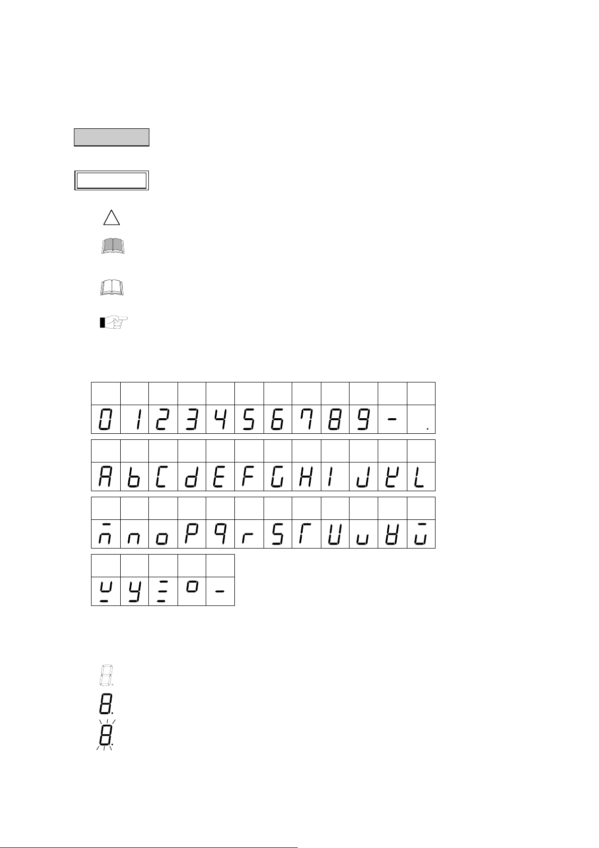
Character Symbols
SYMBOLS
0 1 2 3 4 5 6 7 8 9
Minus Period
(b)
B
A C E F G H I J K L
D
(d)
N O
M P S T U u V W
(n) (o)
Q R
(q) (r)
X Y Z /
Degree
Character LED lighting state:
: Dim lighting
: Bright lighting
: Flashing
i-4
IMR01N02-E6
Page 7

CONTENTS
1. OUTLINE.............................................................................. 1
1.1 Checking the Product ......................................................................................1
1.2 Model Code .....................................................................................................2
1.3 Input/Output Functions ....................................................................................5
1.4 Parts Description .............................................................................................8
2. MOUNTING......................................................................... 11
2.1 Mounting Environment................................................................................... 11
2.2 Mounting Cautions.........................................................................................11
Page
2.3 Dimensions....................................................................................................12
HA400/HA401 ......................................................................................................... 12
HA900/HA901 ......................................................................................................... 12
2.4 Procedures of Mounting and Removing ........................................................13
Mounting procedures............................................................................................... 13
Removing procedures .............................................................................................13
3. WIRING ............................................................................... 14
3.1 Wiring Cautions .............................................................................................14
3.2 Terminal Layout.............................................................................................15
1-input controller...................................................................................................... 15
2-input controller...................................................................................................... 15
3.3 Wiring of Each Terminal ................................................................................16
Power supply........................................................................................................... 16
Output 1 to 3 (OUT1 to OUT3) ................................................................................17
Output 4 to 5 (OUT4 to OUT5) ................................................................................17
Measured input........................................................................................................ 18
Remote input (optional) ........................................................................................... 19
Event input (optional)............................................................................................... 19
CT input/Power feed forward input/Feedback resistance input (optional)............... 20
Communication 1/Communication 2 (optional)........................................................ 20
IMR01N02-E6 i-5
Page 8

4. SETTING............................................................................. 22
4.1 Setting Procedure to Operation .....................................................................22
4.2 Operation Menu.............................................................................................24
Input type and input range display........................................................................... 25
4.3 Key Operation................................................................................................26
Scrolling through parameters................................................................................... 26
Changing set value (SV).......................................................................................... 26
Data Lock Function.................................................................................................. 27
How to restrict operation of the direct keys.............................................................. 27
4.4 Changing Parameter Settings........................................................................28
Change Settings ...................................................................................................... 28
Page
5. SV SETTING & MONITOR MODE...................................... 30
5.1 Display Sequence..........................................................................................30
5.2 Procedure for Set Value (SV) Setting .................................................................31
6. PARAMETER SETTING MODE .........................................32
6.1 Display Sequence..........................................................................................32
6.2 Parameter List ...............................................................................................34
6.3 Description of Each Parameter......................................................................35
Event 1 set value (EV1)/Event 2 set value (EV2)/Event 3 set value (EV3)/
Event 4 set value (EV4)........................................................................................... 35
Control loop break alarm (LBA) time (LbA1, LbA2) ................................................. 35
LBA deadband (Lbd1, Lbd2) ...................................................................................36
Proportional band (1. P, 2. P) for PI/PID control...................................................... 37
Integral time (1. I, 2. I) for PI/PID control ................................................................. 37
Derivative time (1. d, 2. d) for PID control ...............................................................37
Control response parameter (1. rPT, 2. rPT)........................................................... 37
Setting change rate limiter (up) (1.SVrU, 2.SVrU) ................................................38
Setting change rate limiter (down) (1.SVrd, 2.SVrd) .............................................38
Area soak time (AST) .............................................................................................. 39
Link area number (LnKA) ........................................................................................39
i-6
IMR01N02-E6
Page 9

7. SETUP SETTING MODE .................................................... 40
7.1 Display Sequence..........................................................................................40
7.2 Parameter List ...............................................................................................41
7.3 Description of Each Parameter......................................................................42
Heater break alarm 1 (HBA1) set value (HbA1)
Heater break alarm 2 (HBA2) set value (HbA2) ......................................................42
Heater break determination point 1 (HbL1)
Heater break determination point 2 (HbL2) ............................................................. 44
Heater melting determination point 1 (HbH1)
Heater melting determination point 2 (HbH2) .......................................................... 44
PV bias (1. Pb, 2. Pb) ............................................................................................. 44
PV digital filter (1. dF, 2. dF) ...................................................................................44
PV ratio (1. Pr, 2. Pr)............................................................................................... 45
PV low input cut-off (1. PLC, 2. PLC)...................................................................... 45
Proportional cycle time (1. T, 2. T) ..........................................................................45
Device address 1 (Slave address 1) (Add1) .........................................................46
Communication speed 1 (bPS1).............................................................................. 46
Data bit configuration 1 (bIT1)................................................................................. 46
Interval time 1 (InT1) ...............................................................................................47
Device address 2 (Slave address 2) (Add2) .........................................................47
Communication speed 2 (bPS2).............................................................................. 47
Data bit configuration 2 (bIT2)................................................................................. 48
Interval time 2 (InT2) ...............................................................................................48
Infrared communication address (Add3) .................................................................49
Infrared communication speed (bPS3) .................................................................... 49
Set lock level (LCK)................................................................................................. 49
Page
8. ENGINEERING MODE ....................................................... 50
8.1 Display Sequence..........................................................................................50
8.2 Parameter List ............................................................................................... 54
8.3 Precaution Against Parameter Change .........................................................58
8.4 Screen Configuration (F10) .........................................................................63
STOP display selection (SPCH) ............................................................................. 63
Bar graph display selection (dE).............................................................................. 64
Bar graph resolution setting (dEUT)........................................................................ 64
8.5 Direct key (F11).............................................................................................65
Auto/Manual transfer key operation selection (Fn1)................................................ 65
Remote/Local transfer key operation selection (Fn2).............................................. 65
RUN/STOP transfer key operation selection (Fn3) ................................................. 65
IMR01N02-E6
i-7
Page 10

Page
8.6 Input 1 (F21)/Input 2 (F22).............................................................................66
Input type selection (1. InP, 2. InP) .........................................................................66
Display unit selection (1. UnIT, 2. UnIT).................................................................. 67
Decimal point position (1. PGdP, 2. PGdP).............................................................67
Input scale high (1. PGSH, 2. PGSH)...................................................................... 67
Input scale low (1. PGSL, 2. PGSL) ........................................................................ 68
Input error determination point (high) (1. PoV, 2. PoV)......................................... 68
Input error determination point (low) (1. PUn, 2. PUn)........................................68
Burnout direction (1. boS, 2. boS) ........................................................................... 69
Square root extraction selection (1. SQr, 2. SQr)....................................................69
Power supply frequency selection (PFrQ) ............................................................... 69
8.7 Event Input (F23)...........................................................................................70
Event input logic selection (dISL) ............................................................................ 70
8.8 Output (F30) .................................................................................................. 73
Output logic selection (LoGC) .................................................................................73
Output timer setting (oTT1 to oTT5)........................................................................ 74
Alarm lamp lighting condition setting (ALC1, ALC2)................................................ 74
8.9 Transmission Output 1 (F31)/ Transmission Output 2 (F32)/
Transmission Output 3 (F33)......................................................................... 75
Transmission output type selection (Ao1, Ao2, Ao3)............................................... 75
Transmission output scale high (AHS1, AHS2, AHS3) ...........................................75
Transmission output scale low (ALS1, ALS2, ALS3)............................................... 75
8.10 Event 1 (F41)/Event 2 (F42)/Event 3 (F43)/Event 4 (F44)..........................76
Event type selection (ES1, ES2, ES3, ES4)............................................................76
Event hold action (EHo1, EHo2, EHo3, EHo4)........................................................ 78
Event differential gap (EH1, EH2, EH3, EH4) .........................................................79
Event action at input error (EEo1, EEo2, EEo3, EEo4)...........................................80
Event assignment (EVA1, EVA2, EVA3, EVA4)......................................................80
8.11 Current Transformer (CT1) Input (F45)/
Current Transformer (CT2) Input (F46).......................................................81
CT ratio (CTr1, CTr2) ..............................................................................................81
Heater break alarm (HBA) type selection (HbS1, HbS2)......................................... 81
Number of heater break alarm (HBA) delay times (HbC1, HbC2)...........................82
CT assignment (CTA1, CTA2)................................................................................. 82
i-8
8.12 Control (F50) ...............................................................................................83
Hot/Cold start selection (Pd).................................................................................... 83
Input 2_use selection (CAM) ................................................................................... 84
Cascade ratio (CAr)................................................................................................. 84
Cascade bias (CAb) ................................................................................................85
SV tracking (TrK) ....................................................................................................86
IMR01N02-E6
Page 11

Page
8.13 Control 1 (F51)/Control 2 (F52) ...................................................................87
Control action type selection (1. oS, 2. oS) ............................................................. 87
Integral/derivative time decimal point position (1.IddP, 2.IddP)............................... 87
Derivative gain (1. dGA, 2.dGA) ............................................................................ 87
ON/OFF action differential gap (upper) (1. oHH, 2. oHH) ..................................... 88
ON/OFF action differential gap (lower) (1. oHL, 2. oHL).......................................88
Action at input error (high) (1.AoVE, 2.AoVE)....................................................... 89
Action at input error (low) (1.AUnE, 2.AUnE)........................................................89
Manipulated output value at input error (1. PSM, 2. PSM) ...................................... 89
Output change rate limiter (up) (1. orU, 2. orU) ....................................................90
Output change rate limiter (down) (1. ord, 2. ord)................................................. 91
Output limiter (high) (1. oLH, 2. oLH).................................................................... 91
Output limiter (low) (1. oLL, 2. oLL)..................................................................... 91
Power feed forward (1. PFF, 2. PFF) ......................................................................92
Power feed forward gain (1. PFFS, 2. PFFS)..........................................................93
8.14 Autotuning 1 (AT1) (F53) /Autotuning 2 (AT2) (F54) ............................. 93
AT bias (1. ATb, 2. ATb).......................................................................................... 93
AT cycle (1. ATC, 2. ATC) ...................................................................................... 94
AT differential gap time (1. ATH, 2. ATH) ...............................................................95
8.15 Position Proportioning PID Action (F55) ......................................................96
Open/close output neutral zone (Ydb) ................................................................96
O
pen/close output differential gap (YHS) ...........................................................97
Action at feedback resistance (FBR) input error (Ybr)............................................. 97
Feedback resistance (FBR) input assignment (PoSA) ............................................ 97
Feedback adjustment preparation screen (PoS)..................................................... 98
8.16 Communication Function (F60) ...................................................................99
Communication protocol selection (CMPS1, CMPS2) ............................................99
8.17 Set Value (SV) (F70).................................................................................99
Setting change rate limiter unit time (SVrT)............................................................. 99
Soak time unit selection (STdP) .............................................................................. 99
8.18 Set Value 1 (SV1) (F71) /Set Value 2 (SV2) (F72)...............................100
Setting limiter (high) (1. SLH, 2. SLH).................................................................100
Setting limiter (low) (1. SLL, 2. SLL) .................................................................100
8.19 System Information Display (F91) .............................................................101
9. OPERATION ..................................................................... 102
9.1 Control RUN and STOP ..............................................................................102
Operation under control RUN mode ...................................................................... 102
Display at control STOP ........................................................................................ 102
9.2 Configuration of Operation Mode.................................................................103
IMR01N02-E6
i-9
Page 12

Page
9.3 Monitoring Display in Operation...................................................................104
9.4 Autotuning (AT) ...........................................................................................107
Requirements for AT start .....................................................................................107
Requirements for AT cancellation .........................................................................107
9.5 Auto/Manual Transfer .................................................................................. 108
Auto/Manual transfer by front key operation.......................................................... 108
Auto/Manual transfer by direct key (A/M) operation ..............................................109
Auto/Manual transfer by event input......................................................................109
Procedure for setting the manipulated output value (MV) in Manual mode........... 109
9.6 Remote/Local Transfer ................................................................................ 110
Remote/Local transfer by front key operation........................................................ 110
Remote/Local transfer by direct key (R/L) operation ............................................. 110
Remote/Local transfer by event input....................................................................111
9.7 RUN/STOP Transfer.................................................................................... 111
RUN/STOP transfer by front key operation ...........................................................111
RUN/STOP transfer by direct key (R/S) operation ................................................112
RUN/STOP transfer by event input .......................................................................112
9.8 Control Area Transfer .................................................................................. 113
Control area transfer by front key operation.......................................................... 113
Control area transfer by event input ...................................................................... 113
9.9 Start Operation when Power Failure Recovers............................................114
9.10 Ramp/Soak Control ...................................................................................115
10. ERROR DISPLAYS ........................................................ 119
10.1 Overscale and Underscale ........................................................................119
10.2 Self-diagnostic Error .................................................................................. 120
11. TROUBLESHOOTING.................................................... 121
11.1 Display....................................................................................................... 121
11.2 Control.......................................................................................................122
11.3 Operation...................................................................................................123
11.4 Other .........................................................................................................124
12. REMOVING THE INTERNAL ASSEMBLY .................... 125
i-10
IMR01N02-E6
Page 13

APPENDIX
A. Setting Data List ............................................................. A-1
A-1. SV Setting & Monitor Mode........................................................................ A-1
A-2. Setup Setting Mode ................................................................................... A-2
A-3. Parameter Setting Mode ............................................................................ A-5
A-4. Engineering Mode (F10 to F91) ................................................................. A-7
B. Specifications................................................................ A-26
C. Trans Dimensions for Power Feed Forward .............. A-33
Page
D. Current Transformer (CT) Dimensions ....................... A-34
E. Memory Area Data List ................................................. A-35
INDEX.................................................................................... B-1
IMR01N02-E6
i-11
Page 14

MEMO
i-12 IMR01N02-E6
Page 15

1. OUTLINE
This Chapter describes features, package contents and model code, etc.
The digital controller of this high performance type has the following features:
High-speed sampling time (25 ms)
Suitable for fast responding control systems.
Autotuning function corresponding to fast response
• The HA400/HA900 is best suited for applications that reach setpoint quickly (within 30 seconds). *
• The HA401/HA901 is best suited for applications that take more than 30 seconds to reach setpoint. *
* Autotuning a process with a fast response may produce PID constants that would fluctuate the process excessively. If the process is less than
5 minutes to setpoint, RKC recommends adjusting the AT differential gap to less than 10 seconds (default value in the HA401/HA901) prior
to autotuning.
Up to two inputs, 2-loop control in one instrument
Control mode is selectable from 1 loop control, 2-loop control (2 input type only) and cascade control.
Direct function keys
Three Direct Function Keys on the front panel are provided for one-key operation to switch Auto/Manual,
Remote/Local, and RUN/STOP.
Up to 16 memory areas or ramp/soak control
HA400/HA900/HA401/HA901 can store up to 16 sets of control parameters. Ramp/Soak control is available by
using the memory area function.
Two communication ports (optional)
HA400/HA900/HA401/HA901 incorporates a maximum of two communication ports to communicate with a
computer, operation panel, programmable controller, etc.
1.1 Checking the Product
Before using this product, check each of the following:
Model code
Check that there are no scratch or breakage in external appearance (case, front panel, or terminal, etc).
Check that all of the items delivered are complete. (See below)
Instrument 1
Mounting brackets Each 2 Waterproof/dustproof options: each 4
Instruction Manual (IMR01N01-E) 1 Enclosed with instrument
Operation Manual (IMR01N02-E6) 1 This Manual
Communication Instruction Manual (IMR01N03-E)
[RKC communication/Modbus]
Communication Instruction Manual (IMR01N04-E)
[PROFIBUS]
Communication Instruction Manual (IMR01N05-E)
[DeviceNet]
PDA Install Guide (IMT01C01-E) 1 Infrared communication software “RKCIR”
Power feed transformer (100V type or 200V type) 1 Optional
Current transformer (CTL-6-P-N or CTL-12-S56-10L-N) 1 or 2 Optional (sold separately)
If any of the products are missing, damaged, or if your manual is incomplete, please contact RKC sales
office or the agent.
Accessories Q’TY Remarks
Optional
1
With RKC communication or Modbus
Optional
1
With PROFIBUS
Optional
1
With DeviceNet
IMR01N02-E6 1
Page 16

1. OUTLINE
1.2 Model Code
Check whether the delivered product is as specified by referring to the following model code list. If the product
is not identical to the specifications, please contact RKC sales office or the agent.
High-speed AT type:
HA400
HA400-□ □-□ □-□*□ □-□ □ □ □-□/□/Y
HA900
(1) (2) (3) (4) (5) (6) (7) (8) (9) (10) (11) (12) (13) (14)
Standard AT type:
HA401
HA900-□ □-□ □-□*□ □-□ □ □ □-□/□/Y
(1) (2) (3) (4) (5) (6) (7) (8) (9) (10) (11) (12) (13) (14)
(1) Input 1 type
K : K thermocouple J : J thermocouple T : T thermocouple S : S thermocouple R : R thermocouple
A : PLII thermocouple N : N thermocouple E : E thermocouple B : B thermocouple W : W5Re/W26Re
D : RTD (3-wire) [Factory set value: Pt100] 1 C : RTD (4-wire) [Factory set value: Pt100]
3 : Voltage (low) input group (0 to 10 mV, 0 to 100 mV, 0 to 1 V) [Factory set value: 0 to 1 V] 1
6 : Voltage (high) input group (0 to 5 V, 1 to 5 V, 0 to 10 V) [Factory set value: 1 to 5 V]
8 : Current input group (0 to 20 mA, 4 to 20 mA) [Factory set value: 4 to 20 mA]
1
To change the input type, see 8. ENGINEERING MODE (P. 50).
2
Not available as a two-input specification.
(2) Input 2 type
0 : None
K : K thermocouple J : J thermocouple T : T thermocouple S : S thermocouple R : R thermocouple
A : PLII thermocouple N : N thermocouple E : E thermocouple B : B thermocouple W : W5Re/W26Re
D : RTD (3-wire) [Factory set value: Pt100] 1
3 : Voltage (low) input group (0 to 10 mV, 0 to 100 mV, 0 to 1 V) [Factory set value: 0 to 1 V] 1
6 : Voltage (high) input group (0 to 5 V, 1 to 5 V, 0 to 10 V) [Factory set value: 1 to 5 V]
8 : Current input group (0 to 20 mA, 4 to 20 mA) [Factory set value: 4 to 20 mA]
HA901
1
1
1
1
1, 2
Non-isolated type (for remote input) 2
G : Voltage (low) input group (0 to 10 mV, 0 to 100 mV, 0 to 1 V) [Factory set value: 0 to 1 V] 1
V : Voltage (high) input group (0 to 5 V, 1 to 5 V, 0 to 10 V) [Factory set value: 1 to 5 V]
Y : Current input group (0 to 20 mA, 4 to 20 mA) [Factory set value: 4 to 20 mA]
1
To change the input type, see 8. ENGINEERING MODE (P. 50).
2
When 4-wire RTD is selected for input 1, only remote input (no-isolation) can be selected for input 2.
Continued on the next page.
2
1
1
IMR01N02-E6
Page 17

1. OUTLINE
(3) Output 1 (OUT1)
N : None T : Triac output 6 : Voltage output (1 to 5 V DC)
M : Relay contact output 4 : Voltage output (0 to 5 V DC) 7 : Current output (0 to 20 mA DC)
V : Voltage pulse output 5 : Voltage output (0 to 10 V DC) 8 : Current output (4 to 20 mA DC)
(4) Output 2 (OUT2)
N : None T : Triac output 6 : Voltage output (1 to 5 V DC)
M : Relay contact output 4 : Voltage output (0 to 5 V DC) 7 : Current output (0 to 20 mA DC)
V : Voltage pulse output 5 : Voltage output (0 to 10 V DC) 8 : Current output (4 to 20 mA DC)
(5) Power supply voltage
3 : 24 V AC/DC 4 : 100 to 240 V AC
(6) Output 3 (OUT3)
N : None T : Triac output 6 : Voltage output (1 to 5 V DC)
M : Relay contact output 4 : Voltage output (0 to 5 V DC) 7 : Current output (0 to 20 mA DC)
V : Voltage pulse output 5 : Voltage output (0 to 10 V DC) 8 : Current output (4 to 20 mA DC)
(7) Output 4 (OUT4)/Output 5 (OUT5)
N : None
1 : OUT4 (Relay contact output) OUT5 (No output)
2 : OUT4 (Relay contact output) OUT5 (Relay contact output)
(8) Event input (optional)
N : None
1 : Event input [Dry contact input (5 points): for memory area selection]
Continued on the next page.
IMR01N02-E6
3
Page 18

1. OUTLINE
(9) CT input/Power feed forward input/Feedback resistance input (optional)
N : None S : CT 1 point (CTL-12-S56-10L-N)
F : Feedback resistance input T : CT 2 points (CTL-6-P-N)
P : CT 1 point (CTL-6-P-N) U : CT 2 points (CTL-12-S56-10L-N)
1 : Power feed forward input (one 100-120 V AC transformer included)
2 : Power feed forward input (one 200-240 V AC transformer included)
3 : CT 1 point (CTL-6-P-N) + Power feed forward input (one 100-120 V AC transformer included)
4 : CT 1 point (CTL-6-P-N) + Power feed forward input (one 200-240 V AC transformer included)
5 : CT 1 point (CTL-12-S56-10L-N) + Power feed forward input (one 100-120 V AC transformer included)
6 : CT 1 point (CTL-12-S56-10L-N) + Power feed forward input (one 200-240 V AC transformer included)
(10) Communication 1/Event input (optional)
N : None 6 : RS-485 (Modbus)
1 : RS-232C (RKC communication) 8 : RS-232C (Modbus)
5 : RS-485 (RKC communication) D : Event input [Dry contact input (2 points): for operation mode transfer]
(11) Communication 2 (optional)
N : None 6 : RS-485 (Modbus) A : DeviceNet
1 : RS-232C (RKC communication) 7 : RS-422A (Modbus) B : PROFIBUS
4 : RS-422A (RKC communication) 8 : RS-232C (Modbus)
5 : RS-485 (RKC communication)
(12) Waterproof/dustproof (optional)
N : None 1 : Waterproof/dustproof
(13) Case color
N : White A : Black
(14) Instrument version
Y : Version symbol (Infrared communication function included)
4
IMR01N02-E6
Page 19

1. OUTLINE
1.3 Input/Output Functions
This section describes the input/output functions of the instrument. To learn how to set each function, see the
respective page.
INPUT In addition to measured input, 5 optional input functions are available.
Measured input: 1-input or 2-input. (Specify when ordering)
Input types available for measured inputs are shown in the table below.
Thermocouple * K, J, T, S, R, E, B, PLII, N, W5Re/W26Re
RTD * Pt100, JPt100 [Factory set value: Pt100]
Voltage (low) * 0 to 100 mV DC, 0 to 10 mV DC, 0 to 1 V DC [Factory set value: 0 to 1 V DC]
Voltage (High) * 0 to 5 V DC, 1 to 5 V DC, DC 0 to 10 V DC [Factory set value: 1 to 5 V DC]
Current * 0 to 20 mA DC, 4 to 20 mA DC [Factory set value: 4 to 20 mA DC]
*
To change the input type, see 8. ENGINEERING MODE (P. 50).
The second measured input can be used as isolated remote input.
Event input: Optional Event Input hardware is necessary. (Specify when ordering)
Event Input can be used for the following functions. (See P. 70.)
Memory area selection (Number of areas: 1 to 16 or 1 to 8)
Operation mode transfer (RUN/STOP, Remote/Local, Auto/Manual.)
Remote input (non-isolated type):
Remote input is to change a control setpoint by using current or voltage input from an
external device.
Remote input is available with 1-input controller. (Specify when ordering)
Measured input at Input 1 is not isolated from remote input at Input 2. If isolated remote
input is necessary, specify 2-input controller when ordering, and use the second input for
remote input.
Any one of the following input types can be selected. (See P. 66.)
Voltage (low) 0 to 100 mV DC, 0 to 10 mV DC, 0 to 1 V DC
Voltage (High) 0 to 5 V DC, 1 to 5 V DC, DC 0 to 10 V DC
Current 0 to 20 mA DC, 4 to 20 mA DC
CT input: CT input is used for Heater Break Alarm function to detect a heater break or short-circuit.
Up to two CT inputs can be selected. (Specify when ordering)
Only one CT input is available when power feed forward input is selected.
Measured input is not isolated from CT input.
CT inputs accept signal from dedicated current transformers (CT).
Two types of CT available. (See P. 81.)
CTL-6-P-N (for 0 to 30 A)
CTL-12-S56-10L-N (for 0 to 100 A)
IMR01N02-E6
5
Page 20

1. OUTLINE
Power feed forward (PFF) input:
Power feed forward input is used for Power Feed Forward function to achieve accurate
control. PFF monitors power supply voltage variation on a device and compensates
control output from the controller.
Two types of dedicated transformer is available. (Specify either of them when ordering)
PFT-01 100 V type transformer (100 to 120 V AC)
PFT-02 200 V type transformer (200 to 240 V AC)
Feedback resistance input:
Feedback resistance input is used to monitor a valve position when position proportioning
PID control is selected as control action.
Measured input is not isolated from feedback resistance input.
OUTPUT Up to five outputs are available. They may be used as control output, event output or
transmission output by specifying the output type or by activating the output logic
function (output logic selection).
Output1 to 3 (OUT1 to OUT3):
Control output, event output, HBA alarm output, or transmission output can be allocated
to output 1 to 3. (See P. 73 to 80.)
Number of outputs and output types must be specified when ordering.
Output types available for OUT1 to OUT3 are shown in the table below.
Relay contact output 250 V AC, 3A (Resistive load), 1a contact
Voltage pulse output 0/12 V DC (Load resistance: 600 Ω or more)
Triac output 0.4 A (Rated current)
Voltage output 0 to 5 V DC, 1 to 5 V DC, 0 to 10 V DC (Load resistance: 1 kΩ or more)
Current output 0 to 20 mA DC, 4 to 20 mA DC (Load resistance: 600 Ω or less)
OUT3 is isolated from both OUT1 and OUT2.
OUT1 and OUT2 are not isolated from each other except for relay or triac output.
When relay or triac output is used, there is isolation between outputs.
There is isolation between input and output.
There is isolation between output and power supply terminals.
Output 4 to 5 (OUT4 to OUT5):
The output type for OUT4 and OUT5 is relay only. OUT4 and OUT5 can be used for
event output and/or HBA alarm output. (See P. 73 to 80.)
Relay contact output 250 V AC, 1A (Resistive load), 1a contact
Event output function (EV1 to EV4)
The following event types can be selected for EV1 to EV4.
Deviation high Band SV high
Deviation low
Deviation high/low
Process high SV low
Process low LBA (Only EV3 and EV4 can be selected)
6
The maximum number of event output is four.
Output allocation is necessary to output the event state from output terminals. (See P. 73.)
IMR01N02-E6
Page 21
1. OUTLINE
Transmission output 1 to 3 (AO1 to AO3):
Maximum three transmission output can be allocated to OUT1, OUT2, and OUT3.
Maximum number of output available for transmission output varies by other output use
for control output and event output. Parameter values shown in the following table can be
output by transmission output. (See P. 75.)
Input 1 side Measured value (PV), Set value (SV), Manipulated output value (MV),
Deviation (PV−SV)
Input 2 side Measured value (PV), Set value (SV), Manipulated output value (MV),
Deviation (PV−SV)
Output logic function:
Output logic function allocates output functions to output terminals. Logic output such as
OR/AND is available for event output. The following signals are allocated by output logic
function. Transmission output needs to be allocated separately. (See P. 70 to 73.)
Input Analog signal: Control output value (max. 2 points)
Digital signal: Event action state (4 points), HBA action state (max. 2 points),
Position proportioning output state (2 points),
Contact input state (max. 7 points), Control area number (4 points)
Operation state (3points): LOC/MAN/REM
Output Computed output from OUT1 to OUT5.
COMMUNICATION
Communication 1, Communication 2 (optional):
Up to two communication ports are available to communicate with a computer or
programmable controller. When DI 6 and 7 are used, communication port 1 is not
available. (Specify when ordering)
The protocols available for each port are shown in the table below.
Interface *
Protocol *
Open Network *
* Specify when ordering.
Infrared communication:
Infrared communication can be used when sending and receiving data between this
controller and the PDA installed with the RKCIR software.
Communication 1 function * Communication 2 function *
RS-485, RS-232C RS-485, RS-232C, RS-422A
RKC communication, Modbus RKC communication, Modbus
−
PROFIBUS, DeviceNet
IMR01N02-E6
7
Page 22
1. OUTLINE
A
A
AREA
A
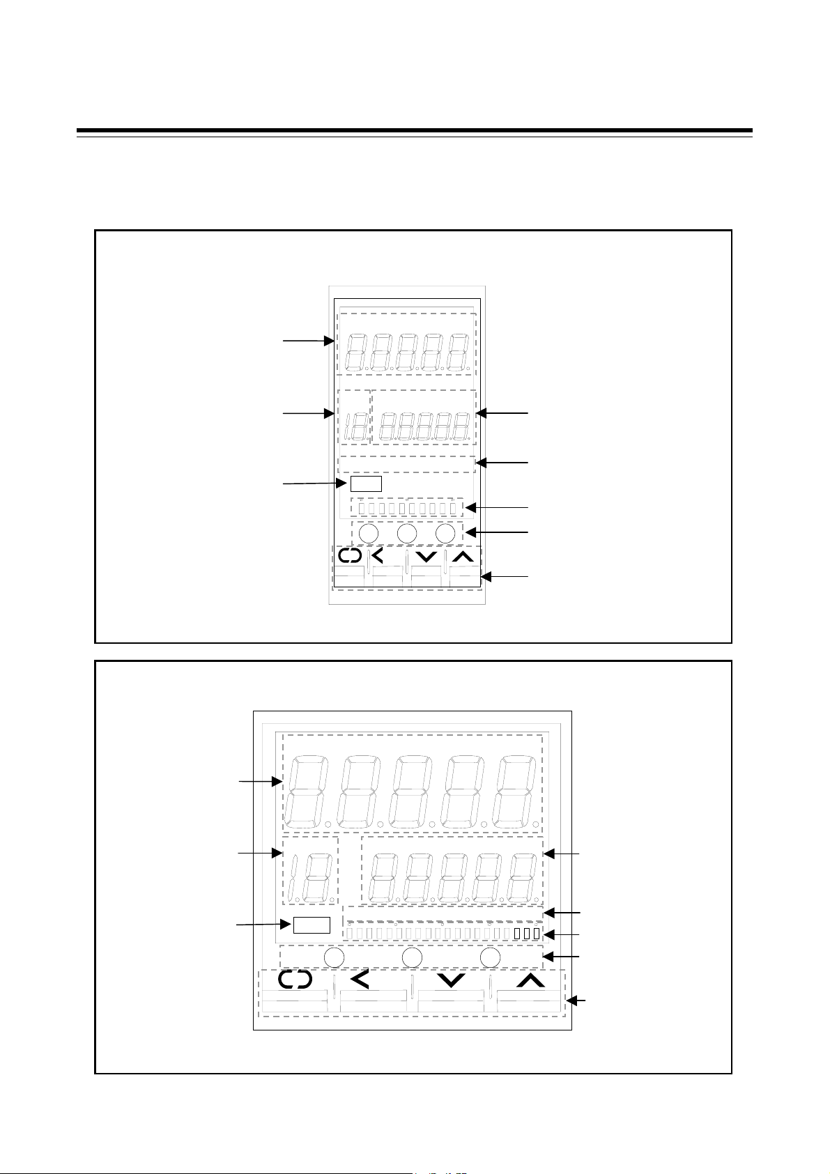
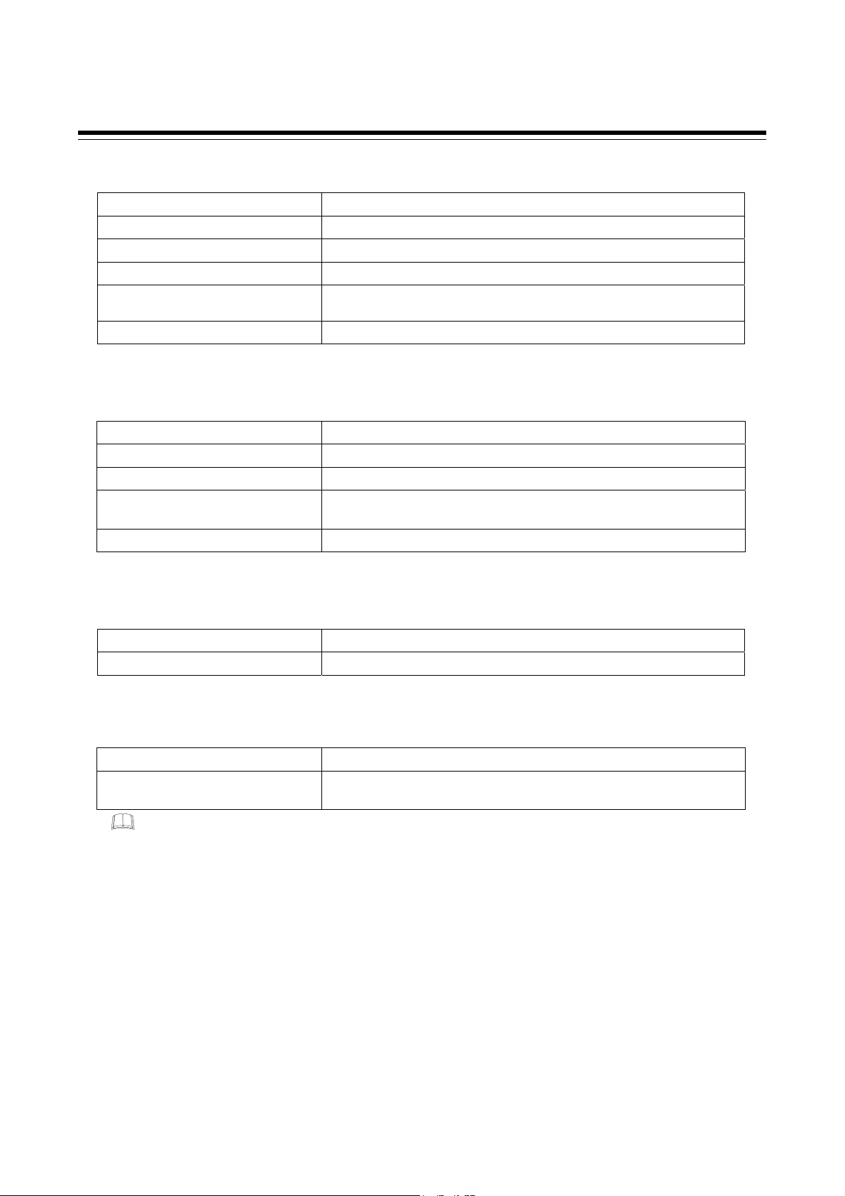
1.4 Parts Description
This chapter describes various display units and the key functions.
HA400/HA401
HA900/HA901
Upper display
rea display
Infrared port
Upper display
rea display
Infrared port
PV1
SET
PV1 PV2 MAN REM AT
AREA PV2 MAN REM AT SV
OUT1 OUT2 OUT3 OUT4 OUT5 ALM
A/M R/L R/S
MODE
SET
PV2 MAN
/M R/L R/S
PV2 MAN REM AT SV
OUT1 OUT2 OUT3 OUT4 OUT5 ALM
MODE
REM
Lower display
Output/Alarm lamp
Bar gragh display
Direct keys
Operation keys
AT
Lower display
Output/Alarm lamp
Bar gragh display
Direct keys
Operation keys
8
IMR01N02-E6
Page 23
Upper display
Measured value 1 (PV1) lamp [Green] Lights when measured value 1 is displayed on the PV1/PV2 display unit.
Measured value 2 (PV2) lamp * [Green] Lights when measured value 2 is displayed on the PV1/PV2 display unit.
Manual (MAN) mode lamp [Green] Lights when operated in manual mode.
Remote (REM) mode lamp [Green] Lights when remote setting function is activated.
Autotuning (AT) lamp [Green]
Measured value (PV1/PV2) display Displays PV1, PV2 or various parameters’ symbols.
* This lamp is activated only with 2-input controller.
Flashes when autotuning is activated.
(After autotuning is completed: AT lamp will become OFF)
Lower display
Measured value 2 (PV2) lamp * [Green] Lights when measured value 2 is displayed on the SV display unit.
Set value (SV) lamp [Green] Lights when set value (SV) is displayed on the SV display unit.
Manual (MAN) mode lamp * [Green] Lights when operated in manual mode.
Autotuning (AT) lamp * [Green] Flashes when autotuning is activated.
(After autotuning is completed: AT lamp will become OFF)
Set value (SV) display Displays SV, PV2 or various parameters’ set values.
* This lamp is activated only with 2-input controller.
Area display
1. OUTLINE
Area (AREA) lamp [Green] Lights when memory area number is displayed.
Memory area display Displays memory area number (1 to 16).
Output/Alarm lamp
Output (OUT1 to OUT5) lamp [Green] Lights when the output corresponding to each lamp is ON.
Alarm (ALM) lamp [Red] Lights when alarm (Event or HBA function) is turned on.
The type of alarm which is on can be checked on the event monitor display.
These lamps works with outputs (control, alarm, retransmission) which are assigned to OUT1 through OUT5.
For assignment of outputs to OUT1 through OUT5, see Transmission Output Type Selection (P.75) and Output Logic
Selection (P.73).
IMR01N02-E6
9
Page 24
1. OUTLINE
−
+
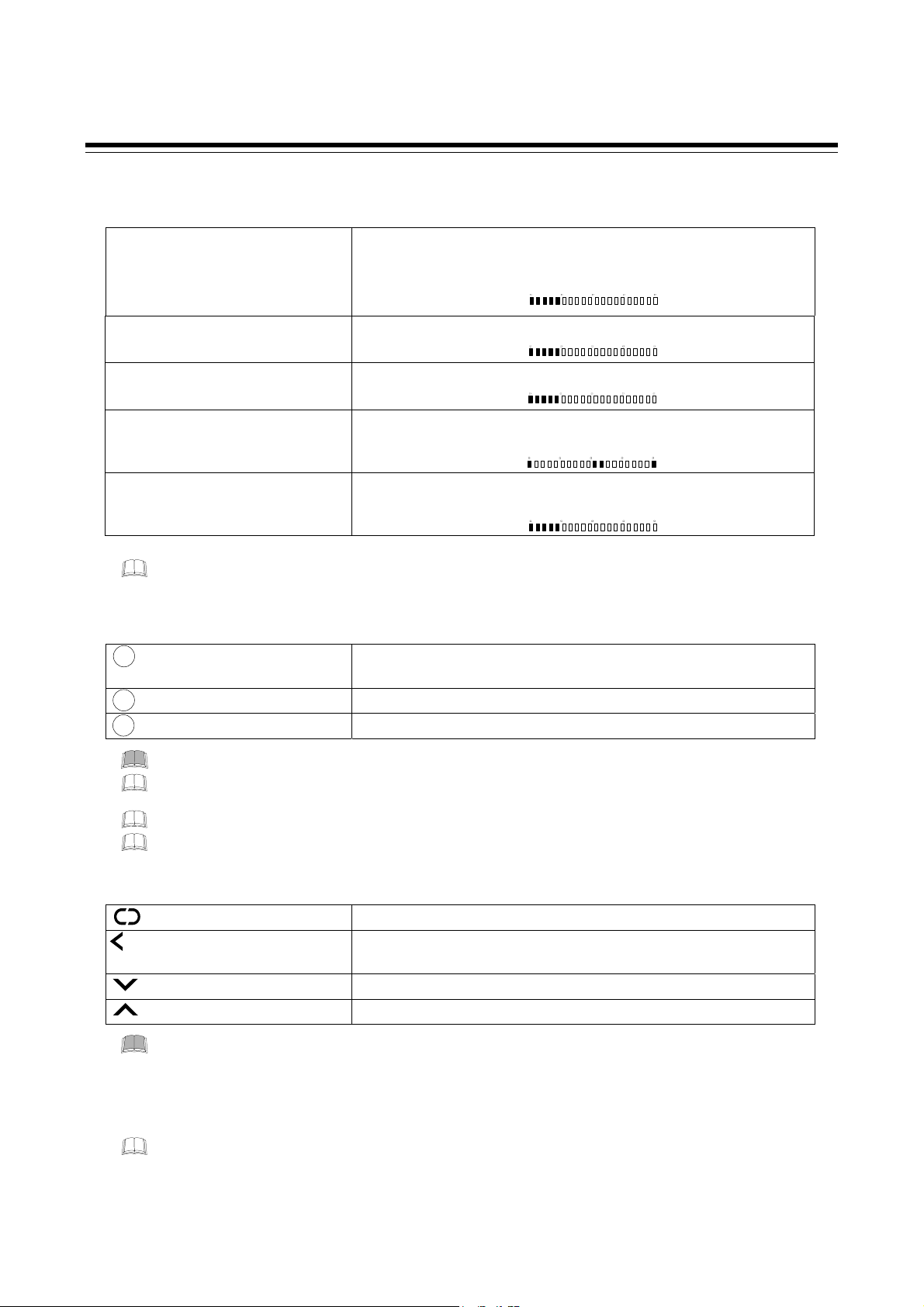
Bar graph display [Green] *
One of the displays shown in the table below can be selected for the bar-graph.
Manipulated output value (MV) display
Measured value display
Set value display Displays the set value (SV). Scaling is available within the input range.
Deviation display
Feedback resistance input value (POS)
display
* The number of dots: 10 dots (HA400/HA401) 20 dots (HA900/HA901)
Displays the manipulated output value (MV). When manipulated output value (MV) is
at 0 % or less, the left-end dot of the bar-graph flashes. When MV exceeds 100 %, the
right-end dot flashes.
[Example]
050
100
Displays the measured value (PV). Scaling is available within the input range.
[Example]
050
100
[Example]
050
100
Displays the deviation between the measured value (PV) and the set value (SV).
When the Deviation display is selected, the dots at both ends of bar-graph light.
[Example]
0
Displays the feedback resistance input value (POS).
(Available with position proportioning PID control)
[Example]
050
100
The bar-graph function is not activated at the factory unless the controller is specified as position proportioning PID controller
when ordered Bar graph display can be selected in the Engineering Mode. See selecting the bar graph display (P.64).
Direct keys
A/M
Auto/Manual transfer key Switching the Auto/Manual control mode between Auto (PID control) mode and Manual
mode.
R/L
Remote/Local transfer key Switching the Remote/Local control mode between Remote control and Local control.
R/S
RUN/STOP transfer key Switching the RUN/STOP mode between RUN and STOP.
To avoid damage to the instrument, never use a sharp object to press keys.
For the Auto/Manual transfer key, it is possible to select among Auto/Manual transfer for (1) Input1, (2) Input2, or (3) both
Input 1 and Input 2. (See P. 65.)
Use/Unuse of Direct Key function are programmable. (See P. 65.)
To prevent operator error, a direct key cannot be operated in positioning adjustment (automatic adjustment).
Operation keys
SET
Set (SET) key Used for parameter calling up and set value registration.
MODE
Shift key Shift digits when settings are changed.
Used to selection operation between modes.
Down key Decrease numerals.
Up key Increase numerals.
To avoid damage to the instrument, never use a sharp object to press keys.
Infrared port
Used when sending and receiving data between this controller and the PDA installed with the RKCIR software.
The RKCIR software can be downloaded from our home page. For this purpose, user registration address and password are required.
For details, PDA INSTALL GUIDE (IMT01C01-E).
10
IMR01N02-E6
Page 25

2. MOUNTING
This chapter describes installation environment, mounting cautions, dimensions and mounting procedures.
To prevent electric shock or instrument failure, always turn off the power before
mounting or removing the instrument.
WARNING
!
2.1 Mounting Environment
(1) This instrument is intended to be used under the following environmental conditions. (IEC61010-1)
[OVERVOLTAGE CATEGORY II, POLLUTION DEGREE 2]
(2) Use this instrument within the following ambient temperature and ambient humidity.
• Allowable ambient temperature: −10 to +50 °C
• Allowable ambient humidity: 5 to 95 % RH
(Absolute humidity: MAX. W. C 29 g/m
(3) Avoid the following conditions when selecting the mounting location:
• Rapid changes in ambient temperature which may cause condensation.
• Corrosive or inflammable gases.
• Direct vibration or shock to the mainframe.
• Water, oil, chemicals, vapor or steam splashes.
• Excessive dust, salt or iron particles.
• Excessive induction noise, static electricity, magnetic fields or noise.
• Direct air flow from an air conditioner.
• Exposure to direct sunlight.
• Excessive heat accumulation.
3
dry air at 101.3 kPa)
2.2 Mounting Cautions
Take the following points into consideration when mounting this instrument in the panel.
• Provide adequate ventilation space so that heat does not build up.
• Do not mount this instrument directly above equipment that generates large amount of heat (heaters,
transformers, semi-conductor functional devices, large-wattage resistors).
• If the ambient temperature rises above 50 °C, cool this instrument with a forced air fan, cooler, or the like.
However, do not allow cooled air to blow this instrument directly.
• In order to improve safety and the immunity to withstand noise, mount this instrument as far away as possible
from high voltage equipment, power lines, and rotating machinery.
High voltage equipment: Do not mount within the same panel.
Power lines: Separate at least 200 mm.
Rotating machinery: Separate as far as possible.
• Mount this instrument in the horizontal direction for panel. If you did installation except a horizontal direction,
this causes malfunction.
IMR01N02-E6 11
Page 26
2. MOUNTING
+
+
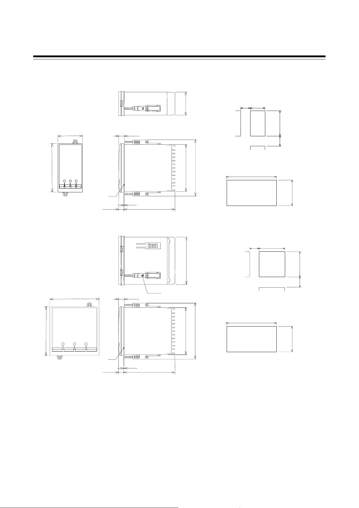
2.3 Dimensions
HA400/HA401
(Unit: mm )
48
44.8
11.1
Individual mounting
+0.6
+0.6
45
45
25
25
+0
+0
+0.8
+0
+0.8
+0
92
92
30
*3, *4
30
96
91.8
110.8
Close mounting
0.6
L
+0
*1
10.1 100
(1)
+0.8
+0
92
L = 48×n-3 n: Number of units (2 ≤ n ≤ 6)
HA900/HA901
Individual mounting
(Unit: mm )
25
91.8
96
11.1
*2
96
91.8
110.8
Close mounting
0.8
L
+0
*1
10.1
(1)
L = 96×n-4 n: Number of units (2 ≤ n ≤ 6)
100
*1 Rubber (Option)
*2 Up to 4 mounting brackets may be used.
*3 If the HA400/HA401s or HA900/HA901s have waterproof/dustproof options, protection will be compromised and not
meet IP65 by close mounting.
*4 When controllers are closely mounted, ambient temperature must not exceed 50 °C.
For mounting of the HA400/HA401 or HA900/HA901, panel thickness must be between 1 to 10 mm. When mounting
multiple HA400/HA401s or HA900/HA901s close together, the panel strength should be checked to ensure proper
support.
92
*3, *4
+0.8
+0
0.8
0
92
30
+0.8
+0
92
12
IMR01N02-E6
Page 27
2. MOUNTING
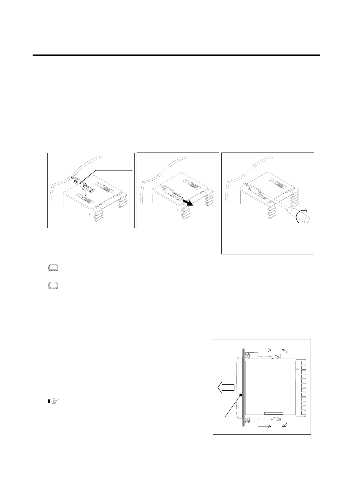
2.4 Procedures of Mounting and Removing
Mounting procedures
1. Prepare the panel cutout as specified in 2.3 Dimensions. (Panel thickness: 1 to 10 mm)
2. Insert the instrument through the panel cutout.
3. Insert the mounting bracket into the mounting groove of the instrument. (Fig. 1)
4. Pull till click sounds to the direction shown by the arrow. (Fig. 2)
5. Tighten up the screw. (Fig. 3)
6. The other mounting bracket should be installed the same way described in 3. to 5.
Fig. 1
HA900/HA901 is used in the above figures for explanation, but
the same mounting procedures also apply to HA400/HA401.
When the instrument is mounted, always secure with two mounting brackets so that upper and lower
mounting brackets are positioned diagonally.
The waterproof/dustproof option on the front of the instrument conforms to IP65 when mounted on the
panel. For effective waterproof/dustproof, the gasket must be securely placed between instrument and
panel without any gap. If gasket is damaged, please contact RKC sales office or the agent.
Removing procedures
Mounting
bracket
Fig. 2
Fig. 3
When using the mounting
screws, only turn one full
revolution after the screw
touches the panel.
1. Loosen the screw of the mounting bracket.
2. Remove the mounting bracket from the case. (Fig. 4)
3. Pull out the instrument from the mounting cutout while
holding the front panel frame of this instrument.
When pulling out only the internal assembly from
the instrument case after being wired, see
12. REMOVING THE INTERNAL ASSEMBLY
(P. 125).
IMR01N02-E6
Fig.4
Pull out
Front panel
frame
13
Page 28

3. WIRING
This chapter describes wiring cautions, wiring layout and wiring of terminals.
To prevent electric shock or instrument failure, do not turn on the power
until all the wiring is completed.
WARNING
!
3.1 Wiring Cautions
• For thermocouple input, use the appropriate compensation wire.
• For RTD input, use low resistance lead wire with no difference in resistance between the three or four lead
wires.
• To avoid noise induction, keep input signal wire away from instrument power line, load lines and power lines
of other electric equipment.
• If there is electrical noise in the vicinity of the instrument that could affect operation, use a noise filter.
− Shorten the distance between the twisted power supply wire pitches to achieve the most effective noise
reduction.
− Always install the noise filter on a grounded panel. Minimize the wiring distance between the noise filter
output and the instrument power supply terminals to achieve the most effective noise reduction.
− Do not connect fuses or switches to the noise filter output wiring as this will reduce the effectiveness of the
noise filter.
• About five seconds are required as preparation time for contact output every time the instrument is turned on.
Use a delay relay when the output line is used for an external interlock circuit.
• Power supply wiring must be twisted and have a low voltage drop.
• For an instrument with 24 V power supply, supply power from a SELV circuit.
• This instrument is not furnished with a power supply switch or fuse. Therefore, if a fuse or power supply
switch is required, install close to the instrument.
Recommended fuse rating: Rated voltage 250 V, Rated current 1 A
Fuse type: Time-lag fuse
• Use the solderless terminal appropriate to the screw size.
Screw size: M3 × 6 (With 5.8 × 8 square washer )
Recommended tightening torque: 0.4 N・m (4 kgf・cm)
Recommended dimension:
6 mm
5.9 mm MAX
3.2 mm MIN
14 IMR01N02-E6
Page 29
3. WIRING
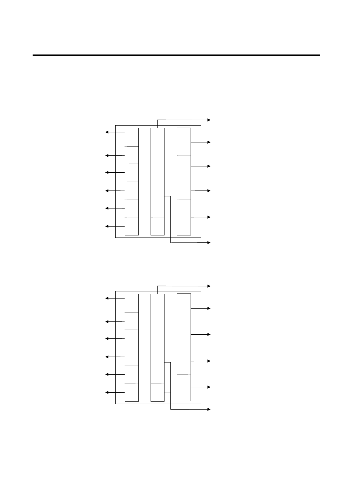
3.2 Terminal Layout
The terminal layout is as follows. HA400/HA401 is used in the figures for explanation, but the same terminal
layouts also apply to HA900/HA901.
1-input controller
Power supply voltage
100 to 240 V AC
24 V AC
24 V AC
Output 5 (OUT5)
Output 4 (OUT4)
Output 3 (OUT3)
Output 2 (OUT2)
Output 1 (OUT1)
2-input controller
1
2
3
4
5
6
7
8
9
10
11
12
25
26
27
28
29
30
31
32
33
34
35
36
13
14
15
16
17
18
19
20
21
22
23
24
Optional
Communication 2
Optional
Communication 1
Event input (DI6 to DI7)
Optional
CT input
Feedback resistance input
Power feed forward input
Optional
Remote input (non-isolated type)
Measured input
Thermocouple/RTD/Voltage/Current
Optional
Event input (DI1 to DI4, DI5)
Power supply voltage
100 to 240 V AC
24 V AC
24 V AC
Output 5 (OUT5)
Output 4 (OUT4)
Output 3 (OUT3)
Output 2 (OUT2)
Output 1 (OUT1)
1
2
3
4
5
6
7
8
9
10
11
12
25
26
27
28
29
30
31
32
33
34
35
36
13
14
15
16
17
18
19
20
21
22
23
24
Optional
Communication 2
Optional
Communication 1
Event input (DI6 to DI7)
Optional
CT input
Feedback resistance input
Power feed forward input
Measured input 2
Thermocouple/RTD/Voltage/Current
Measured input 1
Thermocouple/RTD/Voltage/Current
Optional
Event input (DI1 to DI4, DI5)
IMR01N02-E6
15
Page 30

3. WIRING
A
A
+
−
3.3 Wiring of Each Terminal
Prior to conducting wiring, always check the polarity of each terminal.
The terminal nameplate of this instrument and its descriptions are shown in the following.
Symbols on the input terminal block
correspond to the type of external input
connected to the instrument
Thermocouple Relay contact output
+
TC
−
[Example]
Instrument
inside
23
Relay
24
23
24
Symbols on the output terminal block
NO
correspond to the type (state) of output
sent from the instrument.
Power supply
• Connect the power to terminal numbers 1 and 2.
L
C
100-240 V
100-240 V AC power
supply type
1
2
N
24 V AC power supply type
• The power supply types must be specified when ordering. Power supply voltage for the controller must be
within the range shown below for the controller to satisfy the control accuracy in the specifications.
Power supply type Power consumption
90 to 264 V AC [Power supply voltage range], 50/60 Hz,
(Rating 100 to 240 V AC)
21.6 to 26.4 V AC [Power supply voltage range],
50/60 Hz, (Rating 24 V AC)
21.6 to 26.4 V DC [Power supply voltage range],
(Rating 24 V DC)
• If there is electrical noise in the vicinity of the instrument that could affect operation, use a noise filter.
• Power supply wiring must be twisted and have a low voltage drop.
• For an instrument with 24 V power supply, supply power from a SELV circuit.
• This instrument is not furnished with a power supply switch or fuse. Therefore, if a fuse or power supply
switch is required, install close to the instrument.
Recommended fuse rating: Rated voltage 250 V, Rated current 1 A
Fuse type: Time-lag fuse
L
C
24 V
1
2
N
HA400/HA401: 16.5 VA max. (at 100 V AC), 22.5 VA max. (at 240 V AC)
HA900/HA901: 17.5 VA max. (at 100 V AC), 24.0 VA max. (at 240 V AC)
HA400/HA401: 15.0 VA max. (at 24 V AC)
HA900/HA901: 16.0 VA max. (at 24 V AC)
HA400/HA401: 430 mA max. (at 24 V DC)
HA900/HA901: 470 mA max. (at 24 V DC)
DC
24 V DC power supply type
1
24 V
2
16
IMR01N02-E6
Page 31

11
+
−
+
−
∼
Output 1 to 3 (OUT1 to OUT3)
• Terminal 11 and 12 are for output 1 (OUT1); Terminal 9 and 10 are for output 2 (OUT2); and Terminal 7 and
8 are for output 3 (OUT3).
• Connect an appropriate load according to the output type.
Relay contact output:
11
12
OUT1
NO
9
10
OUT2
NO
7
8
OUT3
NO
Voltage pulse output/Voltage output/Current output
OUT1
12
OUT2
9
+
−
10
OUT3
7
+
−
8
• Number of outputs and output types must be specified when ordering. Control output, event output, HBA
alarm output, or transmission output can be allocated to output 1 to 3. The specifications of each output are as
follows.
Output type Specifications
Relay contact output 250 V AC, 3A (Resistive load), 1a contact Electrical life 300,000 times or more (Rated load)
Voltage pulse output 0/12 V DC (Load resistance: 600 Ω or more)
Triac output 0.4 A (Rated current)
Voltage output
Current output
0 to 5 V DC, 1 to 5 V DC, 0 to 10 V DC (Load resistance: 1 kΩ or more)
Output resolution: 11 bits or more
0 to 20 mA DC, 4 to 20 mA DC (Load resistance: 600 Ω or less)
Output resolution: 11 bits or more
Triac output:
OUT1
11
SSR
12
Example of wiring is as follows:
Inside of
instrument
NO
OUT2
9
10
Load
SSR
OUT3
7
+
SSR
−
8
3. WIRING
+
−
• OUT3 is isolated from both OUT1 and OUT2.
• OUT1 and OUT2 are not isolated from each other except for relay or triac output. When relay or triac output is
used, there is isolation between outputs.
• There is isolation between input and output.
• There is isolation between output and power supply terminals.
Output 4 to 5 (OUT4 to OUT5)
• Terminal 5 and 6 are for output 4 (OUT4); and Terminal 3 and 4 are for output 5 (OUT5).
• Output type is only relay contact output.
Relay contact output 250 V AC, 1A (Resistive load), 1a contact Electrical life 300,000 times or more (Rated load)
• OUT4 and OUT5 can be used for event output and/or HBA alarm output.
5
6
OUT4
NO
3
4
OUT5
NO
IMR01N02-E6
17
Page 32

3. WIRING
+
−
24
22
22
22
+
−
+
−
22
Measured input
• For the 1-input controller, terminals 21 through 24 are allocated to the measured input.
Thermocouple
+
23
TC
24
−
RTD input
A
A
RTD
B
B
21
3-wire
system
22
23
or
4-wire
system
Voltage input Current input
+
23
IN
24
23
IN
24
−
• For the 2-input controller, terminals 22 through 24 are allocated to Input 1, and terminals 19 through 21 are
allocated to Input 2.
Thermocouple Voltage input Current input
RTD input
19
+
20
TC2
21
−
+
23
TC1
24
−
RTD2
RTD1
A
19
B
20
B
21
IN2
19
19
+
20
21
20
IN2
21
−
A
B
23
B
24
23
IN1
24
+
23
IN1
24
−
• The input types needs to be specified when ordering. The input types are as follows.
Thermocouple: K, J, T, S, R, E, B, PLII, N, Voltage (low): 0 to 100 mV DC, 0 to 10 mV DC, 0 to 1 V DC
W5Re/W26Re Voltage (high): 0 to 5 V DC, 1 to 5 V DC, 0 to 10 V DC
RTD: Pt100, JPt100 Current: 0 to 20 mA DC, 4 to 20 mA DC
• For thermocouple input, use an appropriate compensation wire. For RTD input, use the same low resistance
lead wires for all connections.
18
IMR01N02-E6
Page 33

Remote input (optional)
• With non-isolated remote input option, terminals 19 to 20 are allocated to Remote Input.
3. WIRING
+
19
RS
20
−
Any one of the following input types can be selected.
Voltage (low): 0 to 100 mV DC, 0 to 10 mV DC, 0 to 1 V DC
Voltage (high): 0 to 5 V DC, 1 to 5 V DC, 0 to 10 V DC
Current: 0 to 20 mA DC, 4 to 20 mA DC
• Input 2 of the 2-input controller can be used as isolated Remote Input.
• Measured input is not isolated from remote input (non-isolated type).
Event input (optional)
• With Event Input option, terminals 13 through 15 and 30 through 36 are allocated to event input. Event input
option must be specified when ordering.
Dry contact input Dry contact input
COM
DI1
DI2
DI3
DI4
30
31
32
33
34
COM
DI6
DI7
13
14
15
COM
35
DI5
36
• Event Input option can not be selected if Communication 1 function is specified. Use Communication 2
function if both event inputs and communications are necessary.
• Contact input from external devices or equipment should be dry contact input. If it is not dry contact input, the
input should have meet the specifications below.
Contact resistance: At OFF (contact open): 500 kΩ or more At ON (contact closed) 10 Ω or less
• The following functions can be assigned to event inputs.
Memory area selection, RUN/STOP transfer, Remote/Local transfer, Auto/Manual transfer
To assign functions to event inputs, see 8. ENGINEERING MODE (P. 50).
IMR01N02-E6
19
Page 34

3. WIRING
A
+
28
−
28
28
CT input/Power feed forward input/Feedback resistance input (optional)
• With CT input, Power Feed Forward input or feedback resistance input, terminals 16 through 18 are allocated
to the specified input.
• When using CT input, connect CTs to the relevant terminals.
• When using Power Feed Forward input, connect the dedicated transformer included.
• When using feedback resistance input, connect a potentiometer to the relevant terminals.
CT input (1 point)
COM
16
CT1
17
18
CT input (2 points)
COM
16
CT1
CT2
17
18
Power feed forward
input
16
PFF
17
18
CT input +
Power feed forward input
COM
16
CT1
PFF
17
18
Feedback resistance
input
O
16
17
W
18
C
llowance resistance range:
100Ω to 10 kΩ (Standard 135 Ω)
• CT input and feedback resistance input are not isolated between measured input.
Communication 1/Communication 2 (optional)
• With Communication function 1, terminals 13 through 15 are allocated to Communication 1.
• With Communication function 2, terminals 25 through 29 are allocated to Communication 2.
• Communication 1 option can not be selected if Event Input function is specified.
• Conduct wiring to the relevant terminals meeting the specified communication interface. For details of wiring,
see Communication Instruction Manual (IMR01N03-E).*
* See Communication Instruction Manual (IMR01N04-E) for PROFIBUS and Communication Instruction Manual (IMR01N05-E)
for DeviceNet.
[Communication 1]
RS-232C
RS-485
SG
SD
13
14
SG
T/R (A)
13
14
RD
15
T/R (B)
15
[Communication 2]
RS-232C
RS-485
RS-422A
DeviceNet
PROFIBUS
SG
SD
25
26
SG
T/R (A)
25
26
SG
T (A)
V
25
26
CAN-H
25
26
VP
RxD/TxD-P
25
26
RD
27
T/R (B)
27
T (B)
R (A)
27
Drain
CAN-L
27
RxD/TxD-N
DGND
27
R (B)
29
V
29
20
IMR01N02-E6
Page 35

3. WIRING
Example 1: Connection to the RS-232C port of the host computer (master)
HA400/HA900
(Slave)
SG (GND)
SD (TXD)
RD (RXD)
Number of connection: 1 instrument
13
14
15
RS-232C
Shielded wire
Host computer (master)
SG (GND)
SD (TXD)
RD (RXD)
*
RS (RTS)
CS (CTS)
* Short RS and CS within connector
Example 2: Connection to the RS-485 port of the host computer (master)
HA400/HA900
(Slave)
SG
T/R (A)
T/R (B)
SG
T/R (A)
T/R (B)
13
14
15
13
14
15
*R
RS-485
Shielded twisted
*R: Termination resistors (Example: 120Ω 1/2 W)
Paired wire
pair wire
Host computer (master)
SG
T/R (A)
T/R (B)
*R
Maxmum connections: 32 instruments maximum including a host computer
Example 3: Connection to the RS-422A port of the host computer (master)
HA400/HA900
(Slave)
25
SG
T (A)
26
T (B)
27
R (A)
28
R (B)
29
25
SG
T (A)
26
T (B)
27
R (A)
28
R (B)
29
Maxmum connections: 32 instruments maximum including a host computer
RS-422A
Shielded twisted
Paired wire
pair wire
Host computer (master)
SG
T (A)
T (B)
R (A)
R (B)
IMR01N02-E6
21
Page 36

a
4. SETTING
This chapter describes procedures to set operating conditions of a customer and parameter of various setting
modes.
4.1 Setting Procedure to Operation
Conduct necessary setting before operation according to the procedure described below.
Mounting & Wiring
When installing the instrument,
see 2. MOUNTING (P.11) and
3. WIRING (P. 14).
Power ON
Change from RUN to STOP
Factory set value: RUN (Control start)
Press the direct key (R/S) to change the RUN/STOP status from RUN mode to STOP mode.
The parameters in Engineering Mode which should be set according to the application are
settable only when the controller is in STOP mode.
Setting of operating condition
The parameters for controller’s basic functions in Engineering Mode should be changed
according to the application before setting the parameters related to operation.
Be sure to check the parameters for the following settings and change them according to the
application if necessary. Other parameters should be also changed according to the application.
• Input type (RTD input/voltage input/current input specified when the instrument is ordered)
• Power frequency (50 Hz or 60 Hz) [Factory set value: 50 Hz]
• Control action (Direct action or Reverse action) [Factory set value: Reverse action]
• Output logic selection (Output function assignment from OUT1 to OUT5)
[Factory set value: 1-input controller: 1, 2-input controller: 5]
For details of the engineering mode, see 8. ENGINEERING MODE (P. 50).
Setup data setting
Set parameters in Setup Setting Mode:
• Heater break alarm set value (option)
• PV bias, PV digital filter, PV low input cut-off
• Proportional cycle time for control output (Expect voltage and current output)
• Communication (option)
For details of the setup setting mode, see 7. SETUP SETTING MODE (P. 40).
A
Entry to data sheet
Use the sheet of Appendix E, and
make record of setting data of
customer.
22 IMR01N02-E6
Page 37

4. SETTING
r
n
A
Parameter data setting
Set parameters in Parameter Setting Mode:
• Event output/event input function
• PID and control response, etc.
Up to 16 individual sets of parameters in Paramete
Setting Mode and SVs can be stored and used i
Multi-memory Area function.
For details of the parameter setting mode, see
6. PARAMETER SETTING MODE (P. 32).
To use ramp/soak function
Set the Setting change rate
limiter, Area soak time and Link
area number.
Set value (SV) setting
Set the control set value (SV) which is target value of the control. (see P. 30.)
The set value (SV) can be stored up to 16 areas in Multi-memory Area function as well as
parameters in Parameter Setting Mode.
Is Multi-memory Area*
function used?
No
* Factory set value: Memory area 1
Yes
Control Memory area selection
Select the Memory Area in SV Setting & Monitor Mode.
For details of memory area selection, see
9.8 Control Area transfer (P. 113).
Change from STOP to RUN
Press the direct key (R/S) to change the RUN/STOP status from STOP mode to RUN mode.
For details of RUN/STOP transfer, see
9.7 RUN/STOP Transfer (P. 111).
IMR01N02-E6
Operation start
23
Page 38

4. SETTING
y
4.2 Operation Menu
The controller has five different setting modes, and all settable parameters belongs to one of them. The following
chart show how to access different setting mode.
Press the
shift key
while
pressing the
SET key
For the details of key operation, see 4.3 Key Operation (P. 26)
Power ON
Input type/Input range Display
SV setting & Monitor mode
-
Mode be selected during normal
operation
- Change SV
Monitor PV, SV, MV, etc
-
(See P. 30) (See P. 103)
Press the SET key
for 2 seconds
Parameter setting mode *
-
Change parameters related to control
such as PID values.
Up to 16 individual sets of parameters in
-
Parameter Setting Mode and SVs can
be stored and used in Multi-memor
Area function.
Setup setting mode
In this mode, it is possible to set setting
items not stored in the memory area,
setting lock levels, etc.
(See P. 32)
Press the SET key
for 2 seconds
(See P. 40)
This instrument returns to the PV1/SV1 monitor screen if no key
operation is performed for more than 1 minute.
Any parameter which is not used in the controller will not be
displayed except for parameters in Engineering Mode.
Press the shift key
for 1 second
Press the shift key
while pressing the
SET key
Press the shift key
while pressing
the SET key for
2 seconds
* From the Operation Mode and the Parameter Setting Mode,
the display is returned to the SV Setting & Monitor Mode
by pressing the shift key while pressing the SET key.
.
Operation mode *
-
Change Operation status/mode such as
PID/AT, Auto/Manual, and
Remote/Local.
Engineering mode
-
Change basic control functions such as
input/output assignment.
The parameters in Engineering Mode
which should be set according to the
application are settable only when the
controller is in STOP mode.
(See P. 50)
24
IMR01N02-E6
Page 39

4. SETTING
A
A
A
A
Input type and input range display
This instrument immediately confirms inputs type symbol and input range following power ON.
Example: When sensor type of Input 1 and Input 2 is K thermocouple (2-input controller)
Input 1
Input 2
These displays
are not displayed
for the 1-input
controller.
SV setting &
Monitor mode
(PV1/SV1 monitor)
Power ON
PV1
utomatically (in 1 sec)
[1-input controller: in 2 sec]
PV1
utomatically (in 1 sec)
[1-input controller: in 2 sec]
PV2
utomatically
( in 1 sec)
PV1
utomatically
( in 1 sec)
PV1
AREA SV
OUT1
Symbol
Unit for input and SV display
(Celsius: °C, Fahrenheit: °F, Voltage/current input: no character shown)
Input type symbol *
Input range high *
Input range low *
* Input Type Symbol Table
Symbol Input type Input range
K −200.0 to +1372.0 °C, −328.0 to +2501.6 °F
J −200.0 to +1200.0 °C, −328.0 to +2192.0 °F
T −200.0 to +400.0 °C, −328.0 to +752.0 °F
S −50.0 to +1768.0 °C, −58.0 to +3214.4 °F
R −50.0 to +1768.0 °C, −58.0 to +3214.4 °F
PLII 0.0 to 1390.0 °C, 32.0 to 2534.0 °F
N 0.0 to 1300.0 °C, 32.0 to 2372.0 °F
W5Re/W26Re 0.0 to 2300.0 °C, 32.0 to 4172.0 °F
E −200.0 to +1000.0 °C, −328.0 to +1832.0 °F
B 0.0 to 1800.0 °C, 32.0 to 3272.0 °F
Pt100 (3-wire system) −200.0 to +850.0 °C, −328.0 to +1562.0 °F
Pt100 (4-wire system) −200.0 to +850.0 °C, −328.0 to +1562.0 °F
JPt100 (3-wire system) −200.0 to +600.0 °C, −328.0 to +1112.0 °F
JPt100 (4-wire system) −200.0 to +600.0 °C, −328.0 to +1112.0 °F
Voltage (mV, V) Programmable range
Current (mA) (−19999 to +99999)
After the input type symbol and the input range are displayed on the display
unit, the PV1/SV1 monitor screen (SV setting & Monitor mode) is
displayed.
IMR01N02-E6
25
Page 40

4. SETTING
A
AT
A
AT
A
AT
A
AT
A
AT
A
4.3 Key Operation
Basic key operations common to each mode (set item change, set value change and registration) and Data Lock
Function are described in the following.
Scrolling through parameters
• Press to scroll through parameters in the same mode/area.
• To go back to the first parameter, keep pressing SET keys until it is displayed again.
Example: When the SV setting & Monitor mode is selected (2-input controller)
SET
PV2 value
SV2 value
PV1 value
PV2 value
SET SET SET SET
PV1 value
SV1 value
Changing set value (SV)
• The high-lighted digit indicates which digit can be set. Press Shift key to go to a different digit. Every time
the shift key is pressed, the high-lighted digit moves as follows.
AREA SV
Bright lighting
The following is also available when changing the set value.
Increase SV from 199.9 °C to 200.0 °C:
1. Press the shift key to light brightly the tenth digit
(first digit from the right).
2. Press the UP key to change to 0.
The display changes to 200.0.
Decrease SV from 200.0 °C to 190.0 °C:
1. Press the shift key to light brightly the tens digit.
2. Press the DOWN key to change to 9.
The display changes to 190.0.
Decrease SV from 200.0 °C to –100.0 °C:
1. Press the shift key to light brightly the hundreds digit.
2. Press the DOWN key (three times) to change to –1.
The display changes to –100.0.
• To store a new value for the parameter, always press the SET key. The display changes to the next
parameter and the new value will be stored.
A new value will not be stored without pressing SET key after the new value is displayed on the
display.
After a new value has been displayed by using the UP and DOWN keys, the SET key must be pressed
within one minute, or the new value is not stored and the display will return to the PV1/SV1 monitor
screen.
MAN
PV2
PV1
REA
PV1
REA
PV1 PV2 MAN REMAT
REA
PVMANREAT SV
OUT1
OUT OUT OUT OUTALM
PV2
PVMANREAT SV
OUT1
OUT OUT OUT OUTALM
PVMANREAT SV
OUT1
OUT OUT OUT OUTALM
REM
MAN
REM
PV1
REA
PV1
REA
PV1
REA
PV2
PVMANREAT SV
OUT1
OUT OUT OUT OUTALM
PV2
PVMANREAT SV
OUT1
OUT OUT OUT OUTALM
PV2
PVMANREAT SV
OUT1
OUT OUT OUT OUTALM
MAN
MAN
MAN
REM
REM
REM
26
IMR01N02-E6
Page 41

4. SETTING
Data Lock Function
• The Data Lock Function limits access of unauthorized personnel to the parameters and prevents parameter
change by mistake.
• There are 8 set data lock levels. The set data lock level can be set in Setup Setting mode.
Character display Parameters which can be changed Set value
PV2 MAN
PV1
AREA
PV2 MAN REM AT SV
OUT1
REM
OUT2 OUT3 OUT4 OUT5 ALM
All parameters [Factory set value] 00000
SV, EV1 to EV4, Memory Area Selection, Parameters in F10 through F91 00001
AT
All parameters except for EV1 to EV4 00010
SV 00011
All parameters except for SV 00100
EV1 to EV4 00101
All parameters except for SV and EV1 to EV4 00110
No parameter (All Locked) 00111
• Data Lock Level can be changed in both RUN and STOP mode.
• Parameters protected by Data Lock function are still displayed for monitoring.
How to restrict operation of the direct keys
Three Direct Function Keys on the front panel are provided for one-key operation to switch Auto/Manual,
Remote/Local, and RUN/STOP. Use/Unuse of Direct Keys is settable in Engineering Mode. (See P. 65)
IMR01N02-E6
27
Page 42

4. SETTING
4.4 Changing Parameter Settings
Procedures to change parameter settings are shown below.
Change Settings
Example: Change the set value 1 (SV1) of Input 1 from 0.0 °C to 200.0 °C
1. Go to the mode in which the parameter is displayed
If the current mode is not SV setting & Monitor mode, press the shift key while pressing the SET key to
return to the SV setting & Monitor mode.
For the mode transfer, see 4.2 Operation Menu (P. 24).
Setup setting mode
(Set lock level screen)
SET
MODE
SV setting & Monitor mode
(PV1/SV1 monitor screen)
SET
MODE
2. Select the parameter
Press the SET key until “1. SV” (Input 1_SV1 setting screen) is displayed. To go to the next parameter, press
SET key. To go back to the first parameter, keep pressing SET keys until it is displayed again.
SV setting & Monitor mode
(PV1/SV1 monitor screen)
SV setting & Monitor mode
(Input 1_SV1 setting screen)
SET
MODE
SET
MODE
Continued on the next page.
28 IMR01N02-E6
Page 43

3. Shift the high-lighted digit
The high-lighted digit indicates which digit can be set. Press the shift key to high-light the hundreds digit.
4. SETTING
SET
MODE
SET
MODE
4. Change the set value
Press the UP key to change the number to 2.
SET
MODE
SET
MODE
5. Store the set value
Press the SET key to store the new set value. The display goes to the next parameter.
SV setting & Monitor mode
(Input 1_SV1 setting screen)
SV setting & Monitor mode
(Input 1_MV1 monitor screen)
SET
MODE
SET
MODE
IMR01N02-E6
29
Page 44

k
a
A
A
A
A
A
A
5. SV SETTING & MONITOR MODE
5.1 Display Sequence
In SV Setting & Monitor mode, the following operations are possible.
Change the set value (SV)
Change Memory Area
Monitor the measured value (PV) and the manipulated value (MV), etc.
When the power is turned on, the controller goes to this mode after self-diagnostics. Use this mode during
normal operation. To return to this mode from the Operation Mode or the Parameter Setting Mode, press the
shift key while pressing the SET key.
Power ON
(#)
PV1
REA SV
(#)
SET key
PV2
REA SV
(#)
SET key
PV1
REA
PV2
SET key
REA
SET key
REA
SET key
SET key
SET key
SET key
* With the setting change rate limiter when the set value is changed, the displayed set value changes according to the ramp-up/down rate.
Parameters which are not related to existing functions on the controller are not displayed.
This instrument returns to the PV1/SV1 monitor screen if no key operation is performed for more than
one minute. [Exempts, screen of (#) mark]
For the monitor screen, see 9.3 Monitoring Display in Operation (P. 104).
For the memory area selection, see 9.8 Control Area Transfer (P. 113).
Parameter setting mode, Setup setting mode, Operation mode, Engineering mode
Press the shift key while pressing the SET key.
Input 1_measured value (PV1)/set value (SV1 ) monitor
Measured value 1 (PV1)
Set value 1 (SV1) *
Remote input: Displays the remote set value
Manual operation: Manipulated output value (MV1) of
input 1 can be set.
Input 2_measured value (PV2)/set value (SV2 ) monitor
Measured value 2 (PV2)
Set value 2 (SV2) *
Manual operation: Manipulated output value (MV2) of
input 2 can be set.
Input 1_measured value (PV1)/Input 2_measured value
(PV2) monitor
Measured value 1 (PV1)
Measured value 2 (PV2)
Input 1_set value (SV1)
Setting range: Input 1_setting limiter (low) to
Input 1_setting limiter (high)
Input 2_set value (SV2)
Setting range: Input 2_setting limiter (low) to
Input 2_setting limiter (high)
Remote input value monitor
Displays the remote set value which is the control target value in
the Remote (REM) mode. Displayed only when the remote input
function is provided.
Display range: Input 1_setting limiter (low) to
Input 1_setting limiter (high)
Cascade monitor
Displays the input value used for cascade control. Displayed
when cascade control is selected.
Display range: Input 2_setting limiter (low) to
Input 2_setting limiter (high)
Input 1_manipulated output value (MV1) monitor
Display range: −5.0 to +105.0 %
(1) (2)(3)(4)(5)(6)
REA
Retrun to PV1/SV1 monitor screen
Input 2_manipulated output value (MV2) monitor
Display range: −5.0 to +105.0 %
SET key
Event monitor
"o" corresponding to each Event is lit when the event is
turned ON
(1): HBA2 (4): EV3 or LBA1
(2): HBA1 (5): EV2
SET key
SET key
SET key
SET key
SET key
SET key
(3): EV4 or LBA2 (6): EV1
Feedback resistance input value monitor
Displays feedback resistance input value (POS) for
position proportioning PID action.
Display range: 0.0 to 100.0 %
Current transformer input value 1 (CT1) monitor
Displays the input value of the CT1 used when the controller
is provided with the heater break alarm 1 function.
Display range: 0.0 to 30.0 A or 0.0 to 100.0 A
The CT input cannot measure less than 0.4 A.
Current transformer input value 2 (CT2) monitor
Displays the input value of the CT2 used when the controller
is provided with the heater break alarm 2 function.
Display range: 0.0 to 30.0 A or 0.0 to 100.0 A
The CT input cannot measure less than 0.4 A.
Memory area selection
Selects the memory area (control area) used for control.
Setting range: 1 to 16
Memory area soak time monitor
Monitors the time elapsed for memory area operation (soa
time) when ramp/soak control by using Multi-memory Are
is performed.
Display range:
0 minute 00.00 second to 9 minutes 59.99 seconds or
0 hour 00 minute 00 second to 9 hours 59 minutes
59 seconds
: Parameters related to multi-memory area function
: Parameters displayed when function is specified.
30 IMR01N02-E6
Page 45

5. SV SETTING & MONITOR MODE
5.2 Procedure for Set Value (SV) Setting
Up to 16 individual sets of SVs and parameters in Parameter Setting Mode can be stored and used in
Multi-memory Area function. Some examples of changing the set value (SV) described in the following. The
same setting procedure applies when parameters corresponding to the Multi-memory Area function are also set.
Change the set value (SV)
Change SV1 of Input 1 from 0.0 °C to 200.0 °C:
1. Press the SET key several times at PV1/SV1 monitor screen
until Input1_SV1 setting screen is displayed.
AREA
2. Press the shift key to high-light the hundreds digit.
The high-light digit indicates which digit can be set.
AREA
3. Press the UP key to change the number to 2.
AREA
4. Press the SET key to store the new value. The display goes
to the next parameter.
(Example: Input 2_SV2 setting screen)
AREA
Change the set value (SV) of another Memory
Area which is not selected for ongoing control
While Memory Area 1 is selected for ongoing control, change
SV1 of Input 1 in Memory Area 3 from 150.0 °C to 100.0 °C:
1. Go to Input 1_SV1 setting scre en. Press the shift key until
the memory area display unit is high-lighted.
The high-lighted digit indicates which digit can be set.
AREA
2. Press the UP key to change to 3. The SV display shows the
set value (SV1) of Input 1 of the memory area 3, and the
number in AREA (Area number) display flashes.
AREA
3. Press the shift key to high-light the tens digit.
The Area number is flashing.
AREA
4. Press the DOWN key to change the number to 0 in the tens
digit.
AREA
5. Press the SET key to store the new value. The display goes
to the next parameter.
(Example: Input 2_SV2 setting screen)
AREA
IMR01N02-E6
31
Page 46

A
A
A
A
A
A
A
A
A
A
A
A
6. PARAMETER SETTING MODE
6.1 Display Sequence
In Parameter Setting mode, the following operations are possible. Set parameters relating to control such as PID
constants, event set values, and the setting change rate limiter. To go to Parameter Setting mode, press and hold
the SET key for 2 seconds at SV Setting & Monitor mode or Setup Setting mode. Up to 16 individual sets of
SVs and parameters in Parameter Setting Mode can be stored and used in Multi-memory Area function.
Ramp/soak control is possible by using Area Soak Time, Link Area Number and Setting Change Rate Limiter
(up/down) in Parameter Setting mode.
or
SV setting & Monitor mode
Press the SET key for 2 seconds
REA
(P.35)
REA
(P.35)
Event 1 set value (EV1)
SET key
Event 2 set value (EV2)
SET key
(When LBA is selected in event 3 or event 4)
REA
(P.35)
REA
(P.35)
Event 3 set value (EV3)
SET key
Event 4 set value (EV4)
SET key
REA
(P.37)
REA
(P.37)
REA
(P.37)
REA
(P.37)
Input 1_proportional band
SET key
Input 1_integral time
SET key
Input 1_derivative time
SET key
Input 1_control response
parameter
SET key
Continued on the next page *
*For 1-input controller: To Input 1_setting change rate limiter (up) screen
For 2-input controller: To Input 2_proportional band screen
Setup setting mode
Control loop break alarm 1 (LBA1)
time
REA
(P.35)
SET key
LBA1 deadband
REA
(P.36)
SET key
Control loop break alarm 2 (LBA2)
time
REA
(P.35)
SET key
LBA2 deadband
REA
(P.36)
SET key
: Parameters related to multi-memory area function
: Parameters displayed when function is specified.
32 IMR01N02-E6
Page 47

•
•
A
A
A
A
A
A
A
A
A
A
A
A
A
A
From Input 1_control response parameter setting screen
(P.37)
(P.37)
(P.37)
(P.37)
(P.38)
(P.38)
(P.38)
(P.38)
(P.39)
(P.39)
SET key
Input 2_proportional band
REA
SET key
Input 2_integral time
REA
SET key
Memory Area
Input 2_derivative time
REA
SET key
Input 2_control response
parameter
REA
SET key
Input 1_setting change rate limiter
(up)
REA
SET key
Input 1_setting change rate limiter
(down)
REA
SET key
Present set value (SV)
Input 2_setting change rate limiter
(up)
REA
SET key
Input 2_setting change rate limiter
(down)
REA
SET key
rea soak time
REA
SET key
Link area number
REA
SET key
Return to first parameter setting item of parameter setting mode
Parameters which are not related to existing functions on the controller are not displayed.
To return the SV Setting & Monitor mode, press the SET key for two seconds, or press the shift key
while pressing the SET key.
This instrument returns to the PV1/SV1 monitor screen if no key operation is performed for more than
one minute.
6. PARAMETER SETTING MODE
Multi-Memory Area function:
Multi-Memory Area function can store up to 16 individual sets
of SVs and parameters in Parameter Setting mode.
One of the Areas is used for control, and the currently selected
area is “Control Area”.
Control Area
Input 1 Input 2
16
15
2
1
Ramp/soak control is possible by using Area Soak Time, Link
Area Number and Setting Change Rate Limiter (up/down) in
Parameter Setting mode.
[Usage example]
Measured value (PV)
Set value (SV) of
memory area 2
rea soak time of
Set value (SV) of
memory area 1
Set value (SV) of
memory area 3
memory area 1
Setting change rate
limiter (up) of memory
area 1
: Parameters related to multi-memory area function
: Parameters displayed when function is specified.
Set value (SV)
Event 1 set value
Event 2 set value
Event 3 set value
Event 4 set value
LBA (Control loop break alarm)
LBA deadband
Proportional band
Integral time
Derivative time
Control response parameter
Setting change rate parameter (up)
Setting change rate parameter (down)
Area soak time
Link area number
Setting change rate
rea soak time of
memory area 2
Setting change rate
limiter (up) of memory
area 2
Memory area 2 Memory area 3 Memory area 1
limiter (down) of
memory area 3
memory area 3
rea soak time of
Time
IMR01N02-E6
33
Page 48

6. PARAMETER SETTING MODE
6.2 Parameter List
Parameter Page Parameter Page
Event 1 set value
(EV1)
Event 2 set value
(EV2)
Event 3 set value
(EV3)
Event 4 set value
(EV4)
Control loop break
alarm 1 (LBA1) time
(LbA1)
LBA1 deadband
(Lbd1)
Control loop break
alarm 2 (LBA2) time
(LbA2)
LBA2 deadband
(Lbd2)
Input 1_proportional
band
(1. P)
P. 35 Input 1_setting change
rate limiter (up)
P. 35 Input 1_setting change
rate limiter (down)
P. 35 Input 2_setting change
rate limiter (up)
P. 35 Input 2_setting change
rate limiter (down)
P. 35 Area soak time
(1.SVrU)
(1.SVrd)
(2. SVrU)
(2.SVrd)
P. 38
P. 38
P. 38
P. 38
P. 39
(AST)
P. 36 Link area number
P. 39
(LnKA)
P. 35
P. 36
P. 37
Input 1_integral time
Input 1_derivative time
Input 1_control response
parameter
(1. rPT)
Input 2_proportional
band
Input 2_integral time
Input 2_derivative time
Input 2_control response
parameter
(2. rPT)
(1. I)
(1. d)
(2. P)
(2. I)
(2. d)
P. 37
P. 37
P. 37
P. 37
P. 37
P. 37
P. 37
34
IMR01N02-E6
Page 49

6. PARAMETER SETTING MODE
6.3 Description of Each Parameter
Event 1 set value (EV1) Event 2 set value (EV2)
Event 3 set value (EV3) Event 4 set value (EV4)
EV1 through EV4 are set values of the event action.
Data range: Deviation: −Input span to +Input span
Process: Input scale low to Input scale high
SV: Input scale low to Input scale high
Factory set value: 50.0
For the 2-input controller, EVs have to be allocated to either Input 1 or Input 2 (Factory Set Value:
Control loop break alarm (LBA) time (LbA1, LbA2)
The LBA time sets the time required for the LBA function to determine there is a loop failure. When the LBA is
output (under alarm status), the LBA function still monitors the measured value (PV) variation at an interval of
the LBA time.
allocated to Input 1). See “Event assignment” in F41 through F44 of the Engineering mode (P. 80).
Data range: OFF (Unused), 1 to 7200 seconds
Factory set value: 480
For the 2-input controller, LBAs have to be allocated to either Input 1 or Input 2 (Factory Set Value:
allocated to Input 1). See “Event assignment” in F41 through F44 of the Engineering mode (P. 80).
LBA Function: The control loop break alarm (LBA) function is used to detect a load (heater) break or a
failure in the external actuator (power controller, magnet relay, etc.), or a failure in the
control loop caused by an input (sensor) break. The LBA function is activated when control
output reaches 0 % (low limit with output limit function) or 100 % (high limit with output
limit function). LBA monitors variation of the measured value (PV) for the length of LBA
time. When the LBA time has elapsed and the PV is still within the alarm determination
range, the LBA will be ON.
[Alarm action]
LBA determination range: Temperature input: 2 °C [2 °F] fixed
Voltage/current input: 0.2 % fixed
• When the output reaches 0 % (low limit with output limit function)
For direct action: When the LBA time has passed and the PV has not risen beyond the
alarm determination range, the alarm will be turned on.
For reverse action: When the LBA time has passed and the PV has not fallen below the
alarm determination range, the alarm will be turned on.
• When the output exceeds 100 % (high limit with output limit function)
For direct action: When the LBA time has passed and the PV has not fallen below the
alarm determination range, the alarm will be turned on.
For reverse action: When the LBA time has passed and the PV has not risen beyond the
alarm determination range, the alarm will be turned on.
IMR01N02-E6
If the autotuning function is used, the LBA time is automatically set twice as large as the integral time.
The LBA setting time will not be changed even if the integral time is changed.
35
Page 50

6. PARAMETER SETTING MODE
A
LBA deadband (Lbd1, Lbd2)
The LBA deadband gives a neutral zone to prevent the control loop break alarm (LBA) from malfunctioning
caused by disturbance.
Data range: 0.0 to Input span
Factory set value: 0.0
LBA Deadband function:
The LBA may malfunction due to external disturbances. To prevent malfunctioning due to
external disturbance, LBA deadband (LBD) sets a neutral zone in which LBA is not
activated. When the measured value (PV) is within the LBD area, LBA will not be
activated. If the LBD setting is not correct, the LBA will not work correctly.
LBD differential gap *
Alarm area Alarm area
Low High
* TC/RTD input: 0.8 °C [°F] (fixed) Voltage/current input: 0.8 % of span (fixed)
: During temperature rise: Alarm area
During temperature fall: Non-alarm area
B: During temperature rise: Non-alarm area
During temperature fall: Alarm area
AB
Non-alarm area
Set value (SV) LBD set value
If the LBA function detects an error occurring in the control loop, but cannot specify the location, a
check of the control loop in order. The LBA function does not detect a location which causes alarm
status. If LBA alarm is ON, check each device or wiring of the control loop.
When AT function is activated or the controller is in STOP mode, the LBA function is not activated.
If the LBA setting time does not match the controlled object requirements, the LBA setting time
should be lengthened. If setting time is not correct, the LBA will malfunction by turning on or off at
inappropriate times or not turning on at all.
While the LBA is ON (under alarm status), the following conditions cancel the alarm status and LBA
will be OFF.
• The measured value (PV) rises beyond (or falls below) the LBA determination range within
the LBA time
.
• The measured value (PV) enter within the LBA deadband.
36
IMR01N02-E6
Page 51

6. PARAMETER SETTING MODE
Proportional band (1. P, 2. P) for PI/PID control
Data range: TC/RTD input: 0 to Input span (Unit: °C [°F])
Voltage/current input: 0.0 to 1000.0 % of input span
0 (0.0): ON/OFF action
Factory set value: Input 1_Proportional band (1. P): 30.0
Input 2_Proportional band (2. P): 30.0
Related parameters: ON/OFF action differential gap (upper/lower) (P. 88)
Integral time (1. I, 2. I) for PI/PID control
Integral action is to eliminate offset between SV and PV by proportional action. The degree of Integral action is
set by time in seconds.
Data range: OFF (PD action),
1 to 3600 seconds, 0.1 to 3600.0 seconds, or 0.01 to 360.00 seconds
Factory set value: Input 1_Integral time (1. I): 240.00
Input 2_Integral time (2. I): 240.00
Related parameters: Integral/derivative time decimal point position selection (P. 87)
Derivative time (1. d, 2. d) for PID control
Derivative action is to prevent rippling and make control stable by monitoring output change. The degree of
Derivative action is set by time in seconds.
Data range: OFF (PI action),
1 to 3600 seconds, 0.1 to 3600.0 seconds, or 0.01 to 360.00 seconds
Factory set value: Input 1_Derivative time (1. d): 60.00
Input 2_Derivative time (2. d): 60.00
Related parameters: Integral/derivative time decimal point position selection (P. 87)
Control response parameter (1. rPT, 2. rPT)
The control response for the set value (SV) change can be selected among Slow, Medium, and Fast.
Data range: 0: Slow 1: Medium 2: Fast
Factory set value: Input 1_Control response parameter (1. rPT): 0
Input 2_Control response parameter (2. rPT): 0
Control Response: The control response for the set value (SV) change can be selected among Slow, Medium,
and Fast. If a fast response is required, Fast is chosen. Fast may cause overshoot. If
overshoot is critical, Slow is chosen.
Measured value (PV)
Set value (SV2)
Fast
Medium
IMR01N02-E6
Change
Set value (SV1)
Slow
Set value (SV) change point
Time
37
Page 52

6. PARAMETER SETTING MODE
Setting change rate limiter (up) (1. SVrU, 2. SVrU)
This function is to allow the set value (SV) to be automatically changed at specific rates when a new set value
(SV). SVrU is used when the SV is changed to a higher SV.
Data range: OFF (Unused), 0.1 to Input span/unit time
Factory set value: Input 1_Setting change rate limiter (up) (1. SVrU): OFF
Input 2_Setting change rate limiter (up) (2. SVrU): OFF
The unit time can be changed by the setting change rate limiter unit time in the Engineering mode
(P. 99). (Factory set value: 60 seconds)
Setting change rate limiter (down) (1. SVrd, 2. SVrd)
This function is to allow the set value (SV) to be automatically changed at specific rates when a new set value
(SV). SVrd is used when the SV is changed to a lower SV.
Data range: OFF (Unused), 0.1 to Input span/unit time
Factory set value: Input 1_Setting change rate limiter (down) (1. SVrd): OFF
Input 2_Setting change rate limiter (down) (2. SVrd): OFF
The unit time can be changed by the setting change rate limiter unit time in the Engineering mode
(P. 99). (Factory set value: 60 seconds)
Setting change rate limiter:
Application examples of setting change rate limiter:
Increasing the SV to a higher value
SV
Decreasing the SV to a lower value
SV
[After changing]
[Before changing]
SV
SV
Increase gradually
at specific rate
SV
[Before changing]
SV
[After changing]
Changing the set value
Time
Changing the set value
When the setting change rate limiter is used, the SV will also ramp up or ramp down by the function
at power-on and operation mode change from STOP to RUN.
If the autotuning (AT) function is activated while the SV is ramping up or ramping down by the
setting change rate limiter, AT will starts after the SV finishes ramp-up or ramp-down by the limiter,
and the controller is in PID control mode until AT starts.
When the value of setting change rate limiter is changed during normal operation, the ramp-up or
ramp-down rate will be changed unless the SV already has finished ramp-up or ramp-down by the
function.
If the rate of setting change limiter is set to any value other than “OFF (Unused),” the event re-hold
action to be taken by a set value (SV) change becomes invalid.
Decrease gradually
at specific rate
Time
38
IMR01N02-E6
Page 53

6. PARAMETER SETTING MODE
A
A
A
y
A
Area soak time (AST)
Area Soak Time is used for ramp/soak control function in conjunction with Link Area Number and Setting
Change Rate Limiter (up/down).
Data range: 0 hour 00.00 second to 9 minutes 59.99 seconds or
0 hour 00 minute 00 second to 9 hours 59 minutes 59 seconds
Factory set value: 0.00.00 (0 minute 00.00 second)
The unit time can be changed by the Soak Time Unit Selection in the Engineering mode. (P. 99).
(Factory set value: 0 minute 00.00 second to 9 minutes 59.99 seconds)
The Area Soak Time can be changed during normal operation with ramp/soak control function, but
Read the following example carefully how the time change affects ramp/soak control time. For
example, the Memory area which has 5-minute soak time is executed. When 3 minutes passed, the
Area Soak Time is changed from 5 minutes to 10 minutes. The remaining time of the currently
executed Memory Area is calculated as follows.
(The new soak time 10 minutes) – (lapsed time 3 minutes) = (remaining time 7 minutes)
The old soak time does not have any effect on remaining time.
Set value (SV) of
memory area 1
Present set value (SV)
Measured value (PV)
Area soak time is changed 10 minutes.
rea soak time:
5 minutes
Operation start:
3 minutes
Changing
Time of remaining
operating hour:
7 minutes
Time
For the instrument with the 2-input specification, its area soaking starts based on the arrival at the
memory area set value of Input 1 or that of Input 2, whichever later.
Set value (SV) of
memory area 1
Present set value (SV)
Measured value (PV)
Area soak time
Area soak time start-up
Input 1
Input 2
Time
Link area number (LnKA)
Link Area Number is used for ramp/soak control function in conjunction with Area Soak Time and Setting
Change Rate Limiter (up/down).
Data range: OFF (No link), 1 to 16
Factory set value: OFF
Ramp/Soak Control Function:
Ramp/soak control is possible by using Area Soak Time, Link Area Number and Setting Change Rate
Limiter (up/down) in Parameter Setting mode.
[Usage example]
Present set value (SV)
Measured value (PV)
Set value (SV) of
memor
area 2
Set value (SV) of
memory area 1
Set value (SV) of
memory area 3
rea soak time of
memory area 1
Setting change
rate limiter (up)
of memory area 1
Memory area 1
* The area soak time for the memory area linked last becomes invalid to continue the state of the set value (SV) reached.
rea soak time of
memory area 2
Setting change
rate limiter (up)
of memory area 2
Memory area 2
Setting change rate limiter
(down) of memory area 3
rea soak time of
memory area 3 *
Memory area 3
Time
IMR01N02-E6
39
Page 54

7. SETUP SETTING MODE
7.1 Display Sequence
In Setup Setting mode, the following operations are possible.
Change other operation/control related parameters
Change Communication parameters
Change Data Lock Level
To go to Setup Setting mode from SV Setting & Monitor mode, press the shift key while pressing the SET key.
SV setting & Monitor mode
Press the shift key while pressing the SET key
Heater break alarm
1 (HBA1) set value
(P.42)
SET key
Heater break
determination
point 1
(P.44) (P.45) (P.47)
SET key
Heater melting
determination
point 1
(P.44) (P.44) (P.47)
SET key
Heater break alarm
2 (HBA2) set value
(P.42) (P.44) (P.47)
SET key
Heater break
determination
point 2
(P.44) (P.45) (P.48)
SET key
Heater melting
determination
point 2
(P.44) (P.45) (P.48)
SET key
Input 1_PV bias
(P.44) (P.45)
SET key
Input 1_
PV digital filter
(P.44) (P.46)
SET key
Input 1_PV ratio
(P.45) (P.46)
: Parameters displayed when function is specified.
Input 1_PV low input
cut-off
(P.45) (P.46)
SET key
Input 1_ proportional
cycle time
SET key
Input 2_PV bias
SET key
Input 2_
PV digital filter
SET key
Input 2_PV ratio
SET key
Input 2_PV low input
cut-off
SET key
Input 2_ proportional
cycle time
SET key
Device address 1
(Slave address 1)
SET key
Communication
speed 1
SET key SET key
Return to first parameter setting item of
setup setting mode
Data bit configuration 1
SET key
Interval time 1
SET key
Device address 2
(Slave address 2)
SET key
Communication
speed 2
SET key
Data bit configuration 2
SET key
Interval time 2
SET key
Infrared communication
address
(P.49)
SET key
Infrared communication
speed
(P.49)
SET key
Set lock level
(P.49)
SET key
Parameters which are not related to existing functions on the controller are not displayed.
To return the SV Setting & Monitor mode, press the shift key while pressing the SET key.
This instrument returns to the PV1/SV1 monitor screen if no key operation is performed for more than
one minute.
40 IMR01N02-E6
Page 55

7.2 Parameter List
Parameter Page Parameter Page
7. SETUP SETTING MODE
Heater break alarm 1
(HBA1) set value
Heater break
determination point 1
Heater melting
determination point 1
Heater break alarm 2
(HBA2) set value
Heater break
determination point 2
Heater melting
determination point 2
Input 1_PV bias
Input 1_PV digital filter
Input 1_PV ratio
(HbA1)
(HbL1)
(HbH1)
(HbA2)
(HbL2)
(HbH2)
(1. Pb)
(1. dF)
(1. Pr)
P. 42 Device address 1
(Slave address 1)
P. 44 Communication speed 1
P. 44 Data bit configuration 1
P. 42 Interval time 1
P. 44 Device address 2
(Slave address 2)
P. 44 Communication speed 2
P. 44 Data bit configuration 2
P. 44 Interval time 2
P. 45 Infrared communication
address
(Add1)
(bPS1)
(bIT1)
(InT1)
(Add2)
(bPS2)
(bIT2)
(InT2)
(Add3)
P. 46
P. 46
P. 46
P. 47
P. 47
P. 47
P. 48
P. 48
P. 49
Input 1_PV low input
cut-off
Input 1_ proportional
cycle time
Input 2_PV bias
Input 2_PV digital filter
Input 2_PV ratio
Input 2_PV low input
cut-off
Input 2_ proportional
cycle time
(1. PLC)
(2. PLC)
(1. T)
(2. Pb)
(2. dF)
(2. Pr)
(2. T)
P. 45 Infrared communication
speed
P. 45 Set lock level
P. 44
P. 44
P. 45
P. 45
P. 45
(bPS3)
(LCK)
P. 49
P. 49
IMR01N02-E6
41
Page 56

7. SETUP SETTING MODE
7.3 Description of Each Parameter
Heater break alarm 1 (HBA1) set value (HbA1)
Heater break alarm 2 (HBA2) set value (HbA2)
HBA1 and HBA2 are to set the set values for the heater break alarm (HBA) function. The HBA function detects
a fault in the heating circuit by monitoring the current flowing through the load by a dedicated current
transformer (CT).
Up to two heater break alarms are available with the controller. CT input 1 is for HBA1, and CT input 2 for
HBA2. CT inputs can be assigned to one output from OUT1 to OUT5. To use HBA for a three-phase load, both
CT inputs can be assigned to the same output.
Two types of heater break alarms, TYPE “A” and TYPE “B” (factory set value: TYPE “B”), are available. An
appropriate type should be selected depending on the application. (Please see “Heater Break Alarm Function”
below.)
These parameters, HBA set values (HbA1 and HbA2) are used for both types. However, each type has different
function and care must be used to set an appropriate set value.
For type “A” HBA,
- Set the set value to approximately 85% of the maximum reading of the CT input.
- Set the set value to a slightly smaller value to prevent a false alarm if the power supply may become
unstable.
- When more than one heater is connected in parallel, it may be necessary to increase the HBA set value to
detect a single heater failure.
For type “B” HBA,
Set the set value to the maximum CT input value. This will be the current when the control is at 100 %
control output. The set value is used to calculate the width of a non-alarm range.
Data range: With CTL-6-P-N (0-30A) : OFF (Not used), 0.1 to 30.0 A
With CTL-12-S56-10L-N (0-100A): OFF (Not used), 0.1 to 100.0 A
Factory set value: OFF
Related parameters: Heater break determination point (P. 44), Heater melting determination point (P. 44),
Heater break alarm (HBA) type selection (P. 81), CT ratio (P. 81), CT assignment (P. 82),
Number of heater break alarm (HBA) delay times (P. 82)
Heater Break Alarm Function:
< Heater break alarm (HBA) type A >
Heater Break Alarm (HBA) type A can only be used with time-proportional control output (relay, voltage
pulse, or triac output). The HBA function monitors the current flowing through the load by a dedicated
current transformer (CT), compares the measured value with the HBA set values, and detects a fault in the
heating circuit.
Low or No current flow (Heater break, malfunction of the control device, etc.): When the control output
is ON and the CT input value is equal to or less than the heater break determination point for the preset
number of consecutive sampling cycles, an alarm is activated.
Over current or short-circuit: When the control output is OFF and the CT input value is equal to or greater
than the heater break determination point for the preset number of consecutive sampling cycles, an alarm is
activated.
Continued on the next page.
42 IMR01N02-E6
Page 57

7. SETUP SETTING MODE
Continued from the previous page.
< Heater break alarm (HBA) type B >
Heater Break Alarm (HBA) type B can be used with both continuous control output (current/voltage
continuous output) and time-proportional control output (relay, voltage pulse output, or triac). The HBA
function assumes that the heater current value is proportional* to the control output value of the controller,
otherwise viewed as the manipulated variable (MV), and compare it with the CT input value to detect a fault
in the heating or cooling circuit.
* It is assumed that the current value flowing through the load is at maximum when the control output from the controller is 100 %, and
the minimum current value flowing through the load is zero (0) when the control output from the controller is 0 %.
Low or No current flow (Heater break, malfunction of the control device, etc.)
The alarm determination point (Low) is calculated as follows:
(Non-alarm range (Low) width) = (HbL1 or HbL2) x (HbA1 or HbA2)
(Alarm determination point (Low) )=((HbA1 or HbA2) x (MV1 or MV2)) – (Non-alarm range (Low) width)
When the CT input value is equal to or less than the heater break determination point for the preset number
of consecutive sampling cycles, an alarm status is produced.
Over current or short-circuit
The alarm determination point (High) is calculated as follows:
(Non-alarm range (High) width) = (HbH1 or HbH2) x (HbA1 or HbA2)
(Alarm determination point (High) )=((HbA1 or HbA2) x (MV1 or MV2)) + (Non-alarm range (High) width)
When the CT input value is equal to or greater than the heater melting determination point for the preset
number of consecutive sampling cycles, an alarm status is produced.
Maximum current value (squared)
Heater melting determination
point
(0.0 to100.0 % of maximum
current)
Non-alarm range (High)
for heater melting
determination
Current value of heater used (squared)
Alarm range of
Over current/
Short-circuit
0 [A]
0 [%]
Alarm range of
Low current/
No current
100 [%]
Computed heater current value
(Proportional to voltage squared)
Non-alarm range (Low) for
heater break
determination
Heater break determination
point
(0.0 to100.0 % of maximum
current)
Manipulated output value of
controller
The current factory set values of HbLs and HbHs are set to 30.0 %. If any of the following
conditions exists, set them to a slightly larger value to prevent a false alarm.
• Heater current values is not proportional to the control output in Phase control.
• There is difference on control output accuracy between the controller and the operating unit
(SCR Power Controller).
• There is a delay on control output between the controller and the operating unit (SCR Power
Controller).
The factory set value of the HBA type is heater break alarm (HBA) type B.
IMR01N02-E6
43
Page 58

7. SETUP SETTING MODE
Heater break determination point 1 (HbL1)
Heater break determination point 2 (HbL2)
Set the heater break determination point for the heater break alarm (HBA) type B.
Data range: Heater break determination point 1:
0.0 to 100.0 % of heater break alarm 1 (HBA1) set value
(0.0: Heater break determination is invalid)
Heater break determination point 2:
0.0 to 100.0 % of heater break alarm 2 (HBA2) set value
(0.0: Heater break determination is invalid)
Factory set value: 30.0
Related parameters: Heater break alarm (HBA) set value (P. 42), Heater melting determination point (P. 44),
Heater break alarm (HBA) type selection (P. 81),
Number of heater break alarm (HBA) delay times (P. 82)
Function: See heater break alarm (HBA) set value (P. 42, P.43)
Heater melting determination point 1 (HbH1)
Heater melting determination point 2 (HbH2)
Set the heater melting determination point for the heater break alarm (HBA) type B.
Data range: Heater melting determination point 1:
0.0 to 100.0 % of heater break alarm 1 (HBA1) set value
(0.0: Heater melting determination is invalid)
Heater melting determination point 2:
0.0 to 100.0 % of heater break alarm 2 (HBA2) set value
(0.0: Heater melting determination is invalid)
Factory set value: 30.0
Related parameters: Heater break alarm (HBA) set value (P. 42), Heater break determination point (P. 44),
Heater break alarm (HBA) type selection (P. 81),
Number of heater break alarm (HBA) delay times (P. 82)
Function: See heater break alarm (HBA) set value (P. 42, P.43)
PV bias (1. Pb, 2. Pb)
PV bias adds bias to the measured value (PV). The PV bias is used to compensate the individual variations of the
sensors or correct the difference between the measured value (PV) of other instruments.
Data range: −Input span to +Input span
Factory set value: Input 1_PV bias (1. Pb): 0
Input 2_PV bias (2. Pb): 0
PV digital filter (1. dF, 2. dF)
This item is the time of the first-order lag filter eliminate noise against the measured input.
Data range: OFF (Unused), 0.01 to 10.00 seconds
Factory set value: HA400/HA900: Input 1_PV digital filter (1. dF): OFF
Input 2_PV digital filter (2. dF): OFF
HA401/HA901: Input 1_PV digital filter (1. dF): 1.00
Input 2_PV digital filter (2. dF): 1.00
44 IMR01N02-E6
Page 59

7. SETUP SETTING MODE
f
PV ratio (1. Pr, 2. Pr)
PV ratio is a multiplier to be applied to the measured value (PV). The PV ratio is used to compensate the
individual variations of the sensors or correct the difference between the measured value (PV) of other
instruments.
Data range: 0.500 to 1.500
Factory set value: Input 1_PV ratio (1. Pr): 1.000
Input 2_PV ratio (2. Pr): 1.000
PV low input cut-off (1. PLC, 2. PLC)
PV low input cut-off is used with Square Root Extraction function. The measured value less than the PV low
input cut-off is ignored to prevent control disturbance caused by input variation at low measured value range.
Data range: 0.00 to 25.00 % of input span
Factory set value: Input 1: PV low input cut-off (1. PLC): 0.00
Input 2: PV low input cut-off (2. PLC): 0.00
Related parameters: Square root extraction selection (P. 69)
PV low input cut-off function:
When input signal square root extraction is used for in flow control, etc., the square root
extraction result varies widely at the low measured value range. The measured value less
than the PV low input cut-off is ignored to calculate control output in order to prevent
control disturbance caused by input variation at low measured value range.
Output
100 %
70.7 %
50 %
When set value o
the PV low input
cut-off is 0 %
0 %
25 %
50 %
When set value of the PV low input cut-off is 15 %
100 %
Input
Proportional cycle time (1. T, 2. T)
Proportional Cycle Time is to set control cycle time for time based control output such as voltage pulse for SSR,
triac and relay output.
Data range: 0.1 to 100.0 seconds
Factory set value: Input 1: Proportional cycle time (1. T):
Relay contact output: 20.0 seconds
Voltage pulse output and triac output: 2.0 seconds
Input 2: Proportional cycle time (2. T):
Relay contact output: 20.0 seconds
Voltage pulse output and triac output: 2.0 seconds
The proportional cycle time becomes invalid when the voltage/current output is selected as control
output type.
IMR01N02-E6
45
Page 60

7. SETUP SETTING MODE
Device address 1 (Slave address 1) (Add1)
Device Address 1 is used to set the slave address of the controller for Communication 1 function (optional).
Data range: 0 to 99 (RKC communication, Modbus)
Factory set value: 0
Do not use the same device address for more than one controller in multi-drop connection. Each
controller must have a unique address in multi-drop connection.
In Modbus communication, two-way communication is not possible when the address is 0.
Communication speed 1 (bPS1)
Communication Speed 1 is to set communication speed for Communication 1 function (optional).
Data range: 2.4: 2400 bps
4.8: 4800 bps
9.6: 9600 bps
19.2: 19200 bps
38.4: 38400 bps
Factory set value: 9.6
Set the same communication speed for both the HA400/HA900/HA401/HA901 (slave) and the
host computer (master).
Data bit configuration 1 (bIT1)
This item is data bit configuration of communication 1 function (optional).
Data range: See below
[Data bit configuration table]
Set value Data bit Parity bit Stop bit
(8n1) 8 Without 1
(8n2) 8 Without 2
(8E1) 8 Even 1
(8E2) 8 Even 2
(8o1) 8 Odd 1
(8o2) 8 Odd 2
(7n1) * 7 Without 1
(7n2) * 7 Without 2
(7E1) * 7 Even 1
(7E2) * 7 Even 2
(7o1) * 7 Odd 1
(7o2) * 7 Odd 2
* When the Modbus communication protocol selected, this setting becomes invalid.
Factory set value: 8n1 (Data bit: 8, Parity bit: Without, Stop bit: 1)
Setting range
of Modbus
Setting range of
RKC communication
46
IMR01N02-E6
Page 61

7. SETUP SETTING MODE
Interval time 1 (InT1)
This item is interval time of communication 1 function (optional).
Data range: 0 to 250 ms
Factory set value: 10
Interval Time function:
The interval time for the HA400/HA900 (HA401/HA901) should be set to provide a time
for host computer to finish sending all data including stop bit and switch the line to
receive status for the host.
If the interval time between the two is too short, the HA400/HA900 (HA401/HA901) may send
data before the host computer is ready to receive it. In this case, communication transmission
cannot be conducted correctly. For a successful communication sequence to occur, the HA400’s
or HA900’s (the HA401’s or HA901’s) interval time must match the specifications of the host
computer.
Device address 2 (Slave address 2) (Add2)
Device Address 2 is used to set the slave address of the controller for Communication 2 function (optional).
Data range: 0 to 99 (RKC communication, Modbus)
0 to 63 (DeviceNet)
0 to 126 (PROFIBUS)
Factory set value: 0
Do not use the same device address for more than one controller in multi-drop connection. Each
controller must have a unique address in multi-drop connection.
In Modbus and PROFIBUS communications, two-way communications are not possible when
the addresses are 0.
Communication speed 2 (bPS2)
Communication Speed 2 is to set communication speed for Communication 2 function (optional).
Data range: 2.4: 2400 bps 125: 125 kbps *
4.8: 4800 bps 250: 250 kbps *
9.6: 9600 bps 500: 500 kbps *
19.2: 19200 bps
38.4: 38400 bps
* A communication speed of 125 to 500 kbps can be selected for DeviceNet.
Factory set value: 9.6
Set the same communication speed for both the HA400/HA900/HA401/HA901 (slave) and the
host computer (master).
Communication speed 2 is not necessary to be selected for PROFIBUS.
IMR01N02-E6
47
Page 62

7. SETUP SETTING MODE
Data bit configuration 2 (bIT2)
This item is data bit configuration of communication 2 function (optional).
Data range: See below
[Data bit configuration table]
Set value Data bit Parity bit Stop bit
(8n1) 8 Without 1
(8n2) 8 Without 2
(8E1) 8 Even 1
(8E2) 8 Even 2
(8o1) 8 Odd 1
(8o2) 8 Odd 2
(7n1) * 7 Without 1
(7n2) * 7 Without 2
(7E1) * 7 Even 1
(7E2) * 7 Even 2
(7o1) * 7 Odd 1
(7o2) * 7 Odd 2
* When the Modbus communication protocol selected, this setting becomes invalid.
Factory set value: 8n1 (Data bit: 8, Parity bit: Without, Stop bit: 1)
Data bit configuration 2 is not necessary to be selected for PROFIBUS and DeviceNet.
Interval time 2 (InT2)
This item is interval time of communication 2 function (optional).
Setting range
of Modbus
Setting range of
RKC communication
Data range: 0 to 250 ms
Factory set value: 10
Interval Time function: See “Interval time 1 (InT1)” on page 47.
If the interval time between the two is too short, the HA400/HA900 (HA401/HA901) may send
data before the host computer is ready to receive it. In this case, communication transmission
cannot be conducted correctly. For a successful communication sequence to occur, the HA400’s
or HA900’s (the HA401’s or HA901’s) interval time must match the specifications of the host
computer.
48
IMR01N02-E6
Page 63

7. SETUP SETTING MODE
Infrared communication address (Add3)
Infrared Communication Address is used to set the device address of the controller for Infrared Communication
function.
Data range: 0 to 99
Factory set value: 0
Infrared communication speed (bPS3)
This item is communication speed of the infrared communication function.
Data range: 9.6: 9600 bps 19.2: 19200 bps
Factory set value: 19.2
The factory set value of the infrared communication speed of your PDA's
*
is 19200 bps.
Data bit, Stop bit and Parity bit on this controller under infrared communication are fixed to the
following settings. The relevant bits on the PDA* are fixed to the same settings as on this controller
prior to factory set value. Therefore do not change them at the site.
• Data bit: 7-bit
• Parity bit: Even
• Stop bit: 1-bit
* The PDA being used is necessary to be installed with the infrared communication software RKCIR.
Set lock level (LCK)
The set lock level restricts parameter setting changes by key operation (Set data lock function).
This function prevents the operator from making errors during operation.
PV2 MAN
PV1
AREA
OUT1
Data range:
(1) Parameters other than set value (SV) and event set value (EV1 to EV4):
AT
REM
0: Unlock 1: Lock
(2) Event set value (EV1 to EV4)
PV2 MAN REM AT SV
0: Unlock 1: Lock
(3) Set value (SV)
OUT2 OUT3 OUT4 OUT5 ALM
(1) (2) (3) (4) (5)
0: Unlock 1: Lock
(4) “0” Fixed (No setting)
(5) “0” Fixed (No setting)
Factory set value: 00000
In the set lock level, data lock is not possible for the following parameters.
• Memory area selection (SV setting & Monitor mode),
• Parameters of function block number F10 to F91 (Engineering mode)
Set Lock Level can be changed in both RUN and STOP mode.
Parameters protected by Data Lock function are still displayed for monitoring.
IMR01N02-E6
49
Page 64

A
8. ENGINEERING MODE
WARNING
!
Parameters in the Engineering mode should be set according to the application before
setting any parameter related to operation. Once the Parameters in the Engineering mode
are set correctly, those parameters are not necessary to be changed for the same
application under normal conditions. If they are changed unnecessarily, it may result in
malfunction or failure of the instrument. RKC will not bear any responsibility for malfunction
or failure as a result of improper changes in the Engineering mode.
Parameters in Engineering mode are settable only when the controller is in STOP mode.
All parameters of the engineering mode are displayed regardless of the instrument specification.
8.1 Display Sequence
To go to Engineering mode, press the shift key for 2 seconds while pressing the SET key at SV Setting &
Monitor mode, Parameter Setting mode, or Setup Setting mode.
SV setting & monitor mode, parameter setting mode, or setup setting mode
(P. 63)
(P. 65)
(P. 66)
(P. 66)
UP or DOWN
key
UP or DOWN
key
UP or DOWN
key
UP or DOWN
key
Press the shift key for 2 seconds while pressing the SET key
(Screen configuration)
SET key
(Direct key)
SET key
(Input 1)
SET key
(Input 2)
SET key SET key SET key SET keySET key SET key SET key
F23
(Event input)
STOP display
selection
uto/Manual transfer
key operation selection
Input 1_input type
selection
Input 1_input error
determination point
(low)
Input 2_input type
selection
Input 2_input error
determination point
(low)
Bar graph display
selection
SET key SET key SET key
Remote/Local transfer
key operation selection
SET key SET key SET key
Input 1_display unit
selection
SET key SET key SET keySET key SET key
Input 1_burnout
direction
SET key SET key SET key
Input 2_display unit
selection
Input 2_burnout
direction
SET key SET key SET key
Bar graph resolution
setting
RUN/STOP transfer
key operation selection
Input 1_decimal point
position
Input 1_squrae root
extraction selection
Input 2_decimal point
position
Input 2_squrae root
extraction selection
Input 1_input scale
high
Power supply
frequency selection
Input 2_input scale
high
Input 1_input error
Input 1_input scale
low
SET key
Input 2_input scale
low
determination point
(high)
SET key
Input 2_input error
determination point
(high)
Continued on the next page.
50 IMR01N02-E6
Page 65

8. ENGINEERING MODE
A
A
(P. 70)
(P. 73)
(P. 75)
(P. 75)
(P. 75)
(P. 76)
(P. 76)
(P. 76)
(P. 76)
(P. 81)
F22
(Input 2)
UP or DOWN
key
(Event input)
UP or DOWN
key
(Output)
UP or DOWN
key
(Transmission output 1)
UP or DOWN
key
(Transmission output 2)
UP or DOWN
key
(Transmission output 3)
UP or DOWN
key
(Event 1)
UP or DOWN
key
(Event 2)
UP or DOWN
key
(Event 3)
UP or DOWN
key
(Event 4)
UP or DOWN
key
(CT1)
UP or DOWN
key
F46
(CT2)
Event input
logic selection
SET key SET key
Output logic
selection
SET key SET key SET key
Transmission output 1
type selection
SET key SET key SET key SET key
Transmission output 2
type selection
SET key SET key SET key SET key
Transmission output 3
type selection
SET key SET key SET key SET key
Event 1 type
selection
SET key SET key SET key
Event 2 type
selection
SET key SET key SET key
Event 3 type
selection
SET key SET key SET key
Event 4 type
selection
SET key SET key SET key
CT1 ratio
SET key SET key SET key
Output 1 timer
setting
Transmission output 1
scale high
Transmission output 2
scale high
Transmission output 3
scale high
Event 1
hold action
Event 2
hold action
Event 3
hold action
Event 4
hold action
Heater break alarm 1
(HBA1) type selection
SET key SET key
Output 2 timer
setting
Transmission output 1
scale low
Transmission output 2
scale low
Transmission output 3
scale low
Event 1
differential gap
SET key SET key SET key
Event 2
differential gap
SET key SET key SET key
Event 3
differential gap
SET key SET key SET key
Event 4
differential gap
SET key SET key SET key
Number of heater break
alarm 1 (HBA1) delay
times
Output 3 timer
setting
Event 1 action at
input error
Event 2 action at
input error
Event 3 action at
input error
Event 4 action at
input error
CT1 assignment
SET key
SET key
Output 4 timer
setting
larm lamp lighting
condition setting 2
Event 1
assignment
Event 2
assignment
Event 3
assignment
Event 4
assignment
Output 5 timer
setting
SET key SET key
condition setting 1
SET key
SET key
larm lamp lighting
Continued on the next page.
IMR01N02-E6
51
Page 66

8. ENGINEERING MODE
(P. 81)
(P. 83)
(P. 87)
UP or DOWN
key
UP or DOWN
key
UP or DOWN
key
F45
(CT1)
(CT2)
(Control)
(Control 1)
CT2 ratio
SET key SET key SET key
Hot/Cold start
selection
SET key SET key SET key
Input 1_control action
type selection
SET key SET key SET key
Input 1_action at input
error (low)
UP or DOWN
key
Input 1_ power feed
forward selection
(P. 87)
(Control 2)
Input 2_control action
type selection
SET key SET key SET key
Input 2_action at input
error (low)
UP or DOWN
key
Input 2_ power feed
forward selection
(P. 93)
UP or DOWN
key
(AT1)
(AT2)
(P. 93)
UP or DOWN
key
Position proportioning PID action)
(
F55
Input 1_AT bias
SET key SET key SET key SET key
Input 2_AT bias
SET key SET key SET key
Heater break alarm 2
(HBA2) type selection
SET key
Input 2_
use selection
Input 1_
integral/derivative
decimal point position
Input 1_manipulated
output value at input
error
SET key
Input 1_ power feed
forward gain
SET key
Input 2_
integral/derivative
decimal point position
Input 2_manipulated
output value at input
error
SET key
Input 2_ power feed
forward gain
SET key
Input 1_AT cycle
Input 2_AT cycle
Number of heater break
alarm 2 (HBA2) delay
times
SET key
Cascade ratio
Input 1_derivative
gain
Input 1_output change
rate limiter (up)
SET key SET key SET key SET key
SET key
Input 2_derivative
gain
Input 2_output change
rate limiter (up)
SET key SET key
SET key
Input 1_AT differential
gap time
Input 2_AT differential
gap time
CT2 assignment
Cascade bias
SET key SET key SET key
Input 1_ON/OFF action
differential gap (upper)
Input 1_output change
rate limiter (down)
Input 2_ON/OFF action
differential gap (upper)
SET key
Input 2_output change
rate limiter (down)
SET key
SV tracking
Input 1_ON/OFF action
differential gap (lower)
SET keySET key SET key
Input 1_output limiter
(high)
Input 2_ON/OFF action
differential gap (lower)
SET key
Input 2_output limiter
(high)
SET key SET key
SET key
Continued on the next page.
Input 1_action at input
error (high)
SET key
Input 1_output limiter
(low)
SET key
Input 2_action at input
error (high)
SET key
Input 2_output limiter
(low)
SET key
52
IMR01N02-E6
Page 67

8. ENGINEERING MODE
A
(Position proportioning PID action)
(P. 96)
(P. 99)
(P. 99)
(P. 100)
(P. 100)
(P. 101)
F54
(AT2)
UP or DOWN
key
UP or DOWN
key
(Communication)
UP or DOWN
key
(SV)
UP or DOWN
key
(SV1)
UP or DOWN
key
(SV2)
UP or DOWN
key
(System information)
UP or DOWN
key
F10
(Screen configuration)
Open/Close output
neutral zone
SET key SET key SET key
Communication 1
protocol selection
SET key SET key SET key
Setting change rate
limiter unit time
SET key SET key SET key
Input 1_setting limiter
(high)
SET key SET key SET key
Input 2_setting limiter
(high)
SET key SET key SET key
ROM version
display
SET key SET key SET key
Open/Close output
differential gap
Communication 2
protocol selection
Soak time unit
selection
Input 1_setting limiter
(low)
Input 2_setting limiter
(low)
Integrated operating
time display
ction at feedback
resistance (FBR) input
error
SET key
Holding peak value
ambient temperature
display
Feedback resistance
(FBR) input
asignment
Power feed transformer
input value display
SET keySET key
Feedback adjustment
preparation screen
SET key SET key
To return to the SV Setting & Monitor mode, press the SET key for two seconds, or press the shift key
while pressing the SET key.
If the key is not pressed for more than one minute, the display will automatically return to the SV
Setting & Monitor mode.
IMR01N02-E6
53
Page 68

8. ENGINEERING MODE
8.2 Parameter List
Function block Parameter Page
. Screen STOP display selection (SPCH) P. 63
(F10.) configuration Bar graph display selection (dE) P. 64
Bar graph resolution setting (dEUT)
Direct key Auto/Manual transfer key operation selection (Fn1) P. 65
(F11.) Remote/Local transfer key operation selection (Fn2)
RUN/STOP transfer key operation selection (Fn3)
Input 1 Input 1_input type selection (1. InP) P. 66
(F21.) Input 1_display unit selection (1. UnIT) P. 67
Input 1_decimal point position (1.PGdP)
Input 1_input scale high (1.PGSH)
Input 1_input scale low (1.PGSL) P. 68
Input 1_input error determination point (high) (1. PoV)
Input 1_input error determination point (low) (1. PUn)
Input 1_burnout direction (1.boS) P. 69
Input 1_square root extraction selection (1. SQr)
Power supply frequency selection (PFrQ)
Input 2 Input 2_input type selection (2. InP) P. 66
(F22.) Input 2_display unit selection (2. UnIT) P. 67
Input 2_decimal point position (2.PGdP)
Input 2_input scale high (2.PGSH)
Input 2_input scale low (2.PGSL) P. 68
Input 2_input error determination point (high) (2. PoV)
Input 2_input error determination point (low) (2. PUn)
Input 2_burnout direction (2.boS) P. 69
Input 2_square root extraction selection (2. SQr)
Event input Event input logic selection (dISL) P. 70
(F23.)
Output Output logic selection (LoGC) P. 73
(F30.) Output 1 timer setting (oTT1) P. 74
Output 2 timer setting (oTT2)
Output 3 timer setting (oTT3)
Output 4 timer setting (oTT4)
Output 5 timer setting (oTT5)
Alarm lamp lighting condition setting 1 (ALC1)
Alarm lamp lighting condition setting 2 (ALC2)
Continued on the next page.
54 IMR01N02-E6
Page 69

8. ENGINEERING MODE
Continued from the previous page.
Function block Parameter Page
. Transmission Transmission output 1 type selection (Ao1) P. 75
(F31.) output 1 Transmission output 1 scale high (AHS1)
Transmission output 1 scale low (ALS1)
Transmission Transmission output 2 type selection (Ao2) P. 75
(F32.) output 2 Transmission output 2 scale high (AHS2)
Transmission output 2 scale low (ALS2)
Transmission Transmission output 3 type selection (Ao3) P. 75
(F33.) output 3 Transmission output 3 scale high (AHS3)
Transmission output 3 scale low (ALS3)
Event 1 Event 1 type selection (ES1) P. 76
(F41.) Event 1 hold action (EHo1) P. 78
Event 1 differential gap (EH1) P. 79
Event 1 action at input error (EEo1) P. 80
Event 1 assignment (EVA1)
Event 2 Event 2 type selection (ES2) P. 76
(F42.) Event 2 hold action (EHo2) P. 78
Event 2 differential gap (EH2) P. 79
Event 2 action at input error (EEo2) P. 80
Event 2 assignment (EVA2)
Event 3 Event 3 type selection (ES3) P. 76
(F43.) Event 3 hold action (EHo3) P. 78
Event 3 differential gap (EH3) P. 79
Event 3 action at input error (EEo3) P. 80
Event 3 assignment (EVA3)
Event 4 Event 4 type selection (ES4) P. 76
(F44.) Event 4 hold action (EHo4) P. 78
Event 4 differential gap (EH4) P. 79
Event 4 action at input error (EEo4) P. 80
Event 4 assignment (EVA4)
CT input 1 (CT1) CT1 ratio (CTr1) P. 81
(F45.) Heater break alarm 1 (HBA1) type selection (HbS1)
Number of heater break alarm 1 (HBA1) delay
(HbC1) P. 82
times
CT1 assignment (CTA1)
IMR01N02-E6
Continued on the next page.
55
Page 70

8. ENGINEERING MODE
Continued from the previous page.
Function block Parameter Page
CT input 2 (CT2) CT2 ratio (CTr2) P. 81
(F46.) Heater break alarm 2 (HBA2) type selection (HbS2)
Number of heater break alarm 2 (HBA2) delay
(HbC2) P. 82
times
CT2 assignment (CTA2)
Control
(F50.)
Hot/Cold start selection (Pd) P. 83
Input 2_use selection (CAM) P. 84
Cascade ratio (CAr)
Cascade bias (CAb) P. 85
SV tracking (TrK) P. 86
Control 1 Input 1_control action type selection (1. oS) P. 87
(F51.) Input 1_integral/derivative decimal point position (1.IddP)
Input 1_derivative gain (1. dGA)
Input 1_ON/OFF action differential gap (upper) (1. oHH) P. 88
Input 1_ON/OFF action differential gap (lower) (1. oHL)
Input 1_action at input error (high) (1.AoVE) P. 89
Input 1_action at input error (low) (1.AUnE)
Input 1_manipulated output value at input error (1. PSM)
Input 1_output change rate limiter (up) (1. orU) P. 90
Input 1_output change rate limiter (down) (1. ord) P. 91
Input 1_output limiter (high) (1. oLH)
Input 1_output limiter (low) (1. oLL)
Input 1_power feed forward selection (1. PFF) P. 92
Input 1_power feed forward gain (1.PFFS) P. 93
Control 2 Input 2_control action type selection (2. oS) P. 87
(F52.) Input 2_integral/derivative decimal point position (2.IddP)
Input 2_derivative gain (2. dGA)
Input 2_ON/OFF action differential gap (upper) (2. oHH) P. 88
Input 2_ON/OFF action differential gap (lower) (2. oHL)
Input 2_action at input error (high) (2.AoVE) P. 89
Input 2_action at input error (low) (2.AUnE)
Input 2_manipulated output value at input error (2. PSM)
Input 2_output change rate limiter (up) (2. orU) P. 90
Input 2_output change rate limiter (down) (2. ord) P. 91
Input 2_output limiter (high) (2. oLH)
Input 2_output limiter (low) (2. oLL)
56
Continued on the next page.
IMR01N02-E6
Page 71

8. ENGINEERING MODE
Continued from the previous page.
Function block Parameter Page
Control 2 Input 2_power feed forward selection (2. PFF) P. 92
(F52.) Input 2_power feed forward gain (2.PFFS) P. 93
Autotuning 1 Input 1_AT bias (1. ATb) P. 93
(F53.) (AT1) Input 1_AT cycle (1. ATC) P. 94
Input 1_AT differential gap time (1. ATH) P. 95
Autotuning 2 Input 2_AT bias (2. ATb) P. 93
(F54.) (AT2) Input 2_AT cycle (2. ATC) P. 94
Input 2_AT differential gap time (2. ATH) P. 95
Position
(F55.)
(F60.) Communication 2 protocol selection (CMPS2)
(F70.) Soak time unit selection (STdP)
(F71.) Input 1_setting limiter (low) (1. SLL)
(F72.) Input 2_setting limiter (low) (2. SLL)
(F91.) information Integrated operating time display (WT)
proportioning
PID action
Communication Communication 1 protocol selection (CMPS1) P. 99
Set value (SV) Setting change rate limiter unit time (SVrT) P. 99
Set value 1 (SV1) Input 1_setting limiter (high) (1. SLH) P. 100
Set value 2 (SV2) Input 2_setting limiter (high) (2. SLH) P. 100
System ROM version display (RoM) P. 101
Holding peak value ambient temperature display (TCJ)
Power feed transformer input value display (HEAT)
Open/Close output neutral zone (Ydb) P. 96
Open/Close output differential gap (YHS) P. 97
Action at feedback resistance (FBR) input error (Ybr)
Feedback resistance (FBR) input assignment (PoSA)
Feedback adjustment preparation screen (PoS) P. 98
IMR01N02-E6
57
Page 72

8. ENGINEERING MODE
8.3 Precaution Against Parameter Change
If any of the following parameters is changed, the set values of relevant parameters are initialized or is
automatically converted according to the new setting. It may result in malfunction or failure of the instrument.
- Input Type Selection of Input 1 (1. InP)
- Input Type Selection of Input 2 (2. InP)
- Engineering Display Unit Selection of Input 1 (1. UnIT)
- Engineering Display Unit Selection of Input 2 (2. UnIT)
- Input 1_Decimal Point Position (1. PGdP)
- Input 2_Decimal Point Position (2. PGdP)
- Event 1 Type Selection (ES1)
- Event 2 Type Selection (ES2)
- Event 3 Type Selection (ES3)
- Event 4 Type Selection (ES4)
- Transmission Output 1 Type Selection (Ao1)
- Transmission Output 2 Type Selection (Ao2)
- Transmission Output 3 Type Selection (Ao3)
Before changing any parameter setting on the above list, always record all parameter settings in
SV setting & monitor mode, setup setting mode, parameter setting mode and engineering mode.
And after the change, always check all parameter settings in SV setting & monitor mode, setup
setting mode, parameter setting mode and engineering mode by comparing them with the
record taken before the change.
When any one of the following parameters’ settings are changed,
- Input Type Selection of Input 1 (1. InP)
- Input Type Selection of Input 2 (2. InP)
- Engineering Display Unit Selection of Input 1 (1. UnIT)
- Engineering Display Unit Selection of Input 2 (2. UnIT)
all parameter settings shown in the table below will be changed to Factory Default
Values according to the new setting. They must be changed according to the
application.
Mode Description
Engineering
mode
Default value
TC input RTD input
Decimal point position 1 (One decimal place)
Input scale high Maximum value of input range 100.0
Input scale low Minimum value of input range 0.0
Input error determination point
(high)
Burnout direction 0 (Upscale)
Transmission output 1 scale high
Transmission output 2 scale high
Transmission output 3 scale high
Input error determination point
(low)
Maximum value of input range + (5 % of input span)
Minimum value of input range − (5 % of input span)
Measured value (PV) and set value (SV): Input scale high
Manipulated output value (MV): 100.0
Deviation: +Input span
Continued on the next page.
Voltage/current
input
58 IMR01N02-E6
Page 73

Continued from the previous page.
Mode Description
Transmission output 1 scale low
Engineering
mode
Cascade ratio 1.000 (Input 2 only)
Cascade bias 0.0 (Input 2 only)
ON/OFF action differential gap (upper)
ON/OFF action differential gap (lower)
AT bias 0
Setting limiter (high) Input scale high
Setting limiter (low) Input scale low
Setup setting
mode
Event 1 set value
Event 2 set value
Event 3 set value
Event 4 set value
Control loop break alarm1 (LBA1) time
Parameter
setting mode
Proportional band 30
Integral time 240.0 seconds
Derivative time 60.0 seconds
Setting change rate limiter (up)
Setting change rate limiter (down)
SV setting &
monitor mode
Transmission output 2 scale low
Transmission output 3 scale low
Event 1 hold action
Event 2 hold action
Event 3 hold action
Event 4 hold action
Event 1 differential gap
Event 2 differential gap
Event 3 differential gap
Event 4 differential gap
PV bias 0
PV ratio 1.000
PV low input cut-off 0.00 %
Control loop break alarm2 (LBA2) time
LBA1 deadband
LBA2 deadband
Control response parameter 0 (Slow)
Set value (SV) 0.0 °C [°F] 0.0 %
8. ENGINEERING MODE
Default value
TC input RTD input
Measured value (PV) and set value (SV): Input scale low
Manipulated output value (MV): 0.0
Deviation: −Input span
0 (Without hold action)
2.0 °C [°F]
1.0 °C [°F] 0.1 % of
50
480 seconds
0.0
OFF (Unused)
Voltage/current
input
0.2 % of
input span
input span
IMR01N02-E6
59
Page 74

8. ENGINEERING MODE
When any one of the following parameters’ settings are changed,
- Event 1 Type Selection (ES1)
- Event 2 Type Selection (ES2)
- Event 3 Type Selection (ES3)
- Event 4 Type Selection (ES4)
all parameter settings shown in the table below will be changed to Factory Default
Values according to the new setting. They must be changed according to the
application.
Default value
Mode Description
Event 1 hold action
Event 2 hold action
Event 3 hold action
Engineering
mode
Event 2 differential gap
Event 3 differential gap
Event 4 differential gap
Parameter
setting
mode
Event 4 hold action
Event 1 differential gap
Event 1 set value
Event 1 set value
Event 1 set value
Event 1 set value
Control loop break alarm1 (LBA1) time
(Event 3 only)
Control loop break alarm2 (LBA2) time
(Event 4 only)
LBA1 deadband (Event 3 only) 0.0
LBA2 deadband (Event 4 only) 0.0
TC input RTD input
0 (Without hold action)
2.0 °C [°F]
50
480 seconds
480 seconds
Voltage/current
input
0.2 % of
input span
When any one of the following parameters’ settings are changed,
- Transmission Output 1 Type Selection (Ao1)
- Transmission Output 2 Type Selection (Ao2)
- Transmission Output 3 Type Selection (Ao3)
all parameter settings shown in the table below will be changed to Factory Default
Values according to the new setting. They must be changed according to the
application.
Default value
60
Mode Description
Transmission output 1 scale high
Transmission output 2 scale high
Engineering
mode
Transmission output 2 scale low
Transmission output 3 scale low
Transmission output 3 scale high
Transmission output 1 scale low
TC input RTD input
Measured value (PV) and set value (SV): Input scale high
Manipulated output value (MV): 100.0
Deviation: +Input span
Measured value (PV) and set value (SV): Input scale low
Manipulated output value (MV): 0.0
Deviation: −Input span
Voltage/current
input
IMR01N02-E6
Page 75

8. ENGINEERING MODE
When any one of the following parameters’ settings are changed,
- Input 1_Decimal Point Position (1. PGdP)
- Input 2_Decimal Point Position (2. PGdP)
all parameter settings shown in the table below will be automatically converted into
the a values to match the new decimal point position as long as the converted values
are in the acceptable range of each parameter. They must be check and changed if
necessary according to the application
Mode Description
Engineering mode
Setup setting mode
Event 1 set value
Event 2 set value
Event 3 set value
Parameter setting mode
LBA deadband
Setting change rate limiter (up)
Setting change rate limiter (down)
SV setting & monitor mode
Input scale high
Input scale low
Input error determination point (high)
Input error determination point (low)
Transmission output 1 scale high
Transmission output 2 scale high
Transmission output 3 scale high
Transmission output 1 scale low
Transmission output 2 scale low
Transmission output 3 scale low
Event 1 hold action
Event 2 hold action
Event 3 hold action
Event 4 hold action
ON/OFF action differential gap (upper)
ON/OFF action differential gap (lower)
Setting limiter (high)
Setting limiter (low)
PV bias
Event 4 set value
Proportional band
Set value (SV)
Continued on the next page.
IMR01N02-E6
61
Page 76

8. ENGINEERING MODE
Continued from the previous page.
Precaution and Example of automatic conversion
• Decimal point position moves in accordance with the setting change.
Example: When the setting of the decimal point position is changed from 0 (no decimal place) to 1 (the first
decimal place) with Input scale high (1.PGSH) set to 800 °C:
(1.PGSH)
The display will change from 800 to 800.0.
• The displayed range of the controller is between −19999 and +99999 regardless of the decimal point
position.
Example: When RTD input is selected for Input 1, and Input Scale Low (1.PGSL) is 200°C, the decimal
point position is changed from 0 to 2:
(1.PGSL)
• When a number of decimal places for the set value is reduced due to the decimal point change, the set
value is rounded off to the first decimal place and will be displayed without any decimal place.
(1.PGSH)
(1.PGSL)
(Changed from 800 to 800.0)
(Input scale low becomes −199.99, because –200.00 is out
of the display range.)
Example: When the decimal point position is changed from 2 (two decimal places) to 0 (no decimal place)
and Input scale high (1.PGSH) is 594.99:
(1.PGSH)
(1.PGSH)
(The figure is rounded off to the first decimal place,
and the Input Scale High 1.PGSH becomes 595.)
In the above example, if the decimal point position is changed back to 2 from 0, “1.PGSH”
becomes 595.00.
62
IMR01N02-E6
Page 77

8. ENGINEERING MODE
A
A
A
A
A
A
8.4 Screen Configuration (F10)
STOP display selection (SPCH)
STOP message for control STOP mode can be displayed either on the upper display or the lower display.
SPCH is to select the display to show the STOP message.
Data range: 0: Displays on the measured value (PV1/PV2) unit (TYPE 1)
1: Displays on the set value (SV) unit (TYPE 2)
Factory set value: 0
There are three different Characters for STOP mode depending on how to be transfered from RUN to
STOP.
TYPE1:
PV1
REA SV
TYPE2:
PV1
REA SV
Display explanations:
RUN RUN STOP
RUN/STOP with
key operation
(KSTP)
PV1
REA SV
PV1
REA SV
(KSTP)
(dSTP)
(dSTP)
PV1
(SToP)
REA SV
PV1
REA SV
(SToP)
RUN/STOP with event input
RUN
(Contact closed)
STOP
(Contact open)
STOP is not displayed (dSTP)
STOP STOP STOP
(KSTP) (SToP)
IMR01N02-E6 63
Page 78

8. ENGINEERING MODE
−
+
Bar graph display selection (dE)
Use to select the contents of the bar graph display.
Data range: 0: No display
1: Input 1_manipulated output value (MV)
2: Input 1_measured value (PV)
3: Input 1_set value (SV)
4: Input 1_deviation value
5: Feedback resistance input value (POS)
6: Input 2_manipulated output value (MV)
7: Input 2_measured value (PV)
8: Input 2_set value (SV)
9: Input 2_deviation value
Factory set value: 0
Related parameters: Bar graph resolution setting (P. 64)
Bar graph display explanation:
Manipulated output value (MV)
display
Measured value (PV) display Scaling is available within the input range.
Set value (SV) display Displays the set value (SV). Scaling is available within the input range.
Deviation value display
Feedback resistance input
value (POS) display
The number of dot points: 10 dots (HA400/HA401) 20 dots (HA900/HA901)
Displays the manipulated output value (MV). When manipulated output value (MV) is
at 0 % or less, the left-end dot of the bar-graph flashes. When MV exceeds 100 %,
the right-end dot flashes.
[Display example]
Displays the deviation between the measured value (PV) and the set value (SV).
When the Deviation display is selected, the dots at both ends of bar-graph light.
A display resolution per dot is settable from 1 to 100.
Displays the feedback resistance input value (POS). It is available only with position
proportioning PID control.
[Display example]
[Display example]
[Display example]
[Display example]
050
050
050
0
050
100
100
100
100
Bar graph resolution setting (dEUT)
Use to set the bar graph display resolution for the deviation display. Set several digits per 1 dot of the bar graph.
Data range: 1 to 100 digit/dot
Factory set value: 100
Related parameters: Bar graph display selection (P. 64)
64
IMR01N02-E6
Page 79

8. ENGINEERING MODE
8.5 Direct Key (F11)
Auto/Manual transfer key operation selection (Fn1)
Use to select Use/Unuse of Auto/Manual transfer key (A/M).
Data range: 0: Unused
1: Auto/Manual transfer for input 1
2: Auto/Manual transfer for input 2
3: Common Auto/Manual transfer for input 1 and input 2
Factory set value: 3
Remote/Local transfer key operation selection (Fn2)
Use to select Use/Unuse of Remote/Local transfer key (R/L).
Data range: 0: Unused
1: Remote/Local transfer
Factory set value: 1
RUN/STOP transfer key operation selection (Fn3)
Use to select Use/Unuse of RUN/STOP transfer key (R/S).
Data range: 0: Unused
1: RUN/STOP transfer
Factory set value: 1
IMR01N02-E6
65
Page 80

8. ENGINEERING MODE
8.6 Input 1 (F21)
Input 2 (F22)
Input type selection (1. InP, 2. InP)
Data range: 0 to 23 (see the following table)
[Input Range Table]
Set value Input type Input range Hardware
0
1
2
3
4
5
6
7
8
9
19
20
21
12
13
22
23
14
15
16
17
18
An input type change may only be made within the hardware groups as shown above.
Do not set to any number (including 10 and 11) which is not described in the input range table
above. This may cause malfunctioning.
4-wire RTD input type (22 and 23) can not be selected for Input type selection of Input 2 (2. InP).
See the above input range table to select input type of the remote input. Input range 0 through
13, 22 or 23 can not be selected for the remote input.
Factory set value: Input 1_Input type selection (1. InP):
Input 2_Input type selection (2. InP):
Related parameters: Display unit selection (P. 67), Decimal point position (P. 67), Input scale high (P. 67),
K −200 to +1372 °C or −328.0 to +2501.6 °F
J −200 to +1200 °C or −328.0 to +2192.0 °F
R −50 to +1768 °C or −58.0 to +3214.4 °F
S −50 to +1768 °C or −58.0 to +3214.4 °F
TC B 0 to 1800 °C or 32.0 to 3272.0 °F
input E −200 to +1000 °C or −328.0 to +1832.0 °F
N 0 to 1300 °C or 32.0 to 2372.0 °F
T −200 to +400 °C or −328.0 to +752.0 °F
W5Re/W26Re 0 to 2300 °C or 32.0 to 4172.0 °F Voltage (low)
PLII 0 to 1390 °C or 32.0 to 2534.0 °F input group
Voltage 0 to 1 V Programmable range
(low) 0 to 100 mV (−19999 to +99999)
input 0 to 10 mV
3-wire system Pt100 −200 to +850 °C or −328.0 to +1562.0 °F
RTD 3-wire system JPt100 −200 to +600 °C or −328.0 to +1112.0 °F
input 4-wire system Pt100 −200 to +850 °C or −328.0 to +1562.0 °F
4-wire system JPt100 −200 to +600 °C or −328.0 to +1112.0 °F
Current 0 to 20 mA Programmable range
input 4 to 20 mA (−19999 to +99999)
Voltage 0 to 10 V Programmable range Voltage (high)
(high) 0 to 5 V (−19999 to +99999)
input 1 to 5 V
Depend on model code. (When not specifying: Type K)
Depend on model code. (When not specifying: Type K)
Input scale low (P. 68)
input group
66
IMR01N02-E6
Page 81

8. ENGINEERING MODE
Display unit selection (1. UnIT, 2. UnIT)
Use to select the temperature unit for thermocouple (TC) and RTD inputs.
Data range: 0: °C
1: °F
Factory set value: Input 1_Display unit selection (1. UnIT): 0
Input 2_Display unit selection (2. UnIT): 0
Decimal point position (1. PGdP, 2. PGdP)
Use to select the decimal point position of the input range.
Data range: Thermocouple (TC) inputs: 0 to 1
RTD inputs: 0 to 2
Voltage (V)/current (I) inputs: 0 to 4
0: No decimal place
1: One decimal place
2: Two decimal places
3: Three decimal places
4: Four decimal places
Factory set value: Input 1_Decimal point position (1. PGdP): 1
Input 2_Decimal point position (2. PGdP): 1
Related parameters: Input type selection (P. 66), Input scale high (P. 67), Input scale low (P. 68)
Input scale high (1. PGSH, 2. PGSH)
Use to set the high limit of the input scale range.
Data range: Thermocouple (TC)/RTD inputs:
Input scale low to Maximum value of the selected input range
Voltage (V)/current (I) inputs:
−19999 to +99999 (Varies with the setting of the decimal point position)
Factory set value: Input 1_Input scale high (1. PGSH):
Thermocouple (TC)/RTD inputs: Maximum value of the selected input range
Voltage (V)/current (I) inputs: 100.0
Input 2_Input scale high (2. PGSH):
Thermocouple (TC)/RTD inputs: Maximum value of the selected input range
Voltage (V)/current (I) inputs: 100.0
Related parameters: Input type selection (P. 66), Decimal point position (P. 67), Input scale low (P. 68)
Input Scale High function:
The input scale range can be easily set by setting the input scale high limit/low limit.
When a voltage/current input type is selected, the input scale high limit can be set lower than the input
scale low limit. (Input scale high limit < Input scale low limit)
IMR01N02-E6
67
Page 82

8. ENGINEERING MODE
Input scale low (1. PGSL, 2. PGSL)
This value is to set the low limit of the input scale range.
Data range: Thermocouple (TC)/RTD inputs:
Minimum value of the selected input range to Input scale high
Voltage (V)/current (I) inputs:
−19999 to +99999 (Varies with the setting of the decimal point position)
Factory set value: Input 1_Input scale low (1. PGSL):
Thermocouple (TC)/RTD inputs: Minimum value of the selected input range
Voltage (V)/current (I) inputs: 0.0
Input 2_Input scale low (2. PGSL):
Thermocouple (TC)/RTD inputs: Minimum value of the selected input range
Voltage (V)/current (I) inputs: 0.0
Related parameters: Input type selection (P. 66), Decimal point position (P. 67), Input scale high (P. 67)
Input Scale Low function:
The input scale range can be easily set by setting the input scale high limit/low limit
When a voltage/current input type is selected, the input scale high limit can be set lower than the input
scale low limit. (Input scale high limit < Input scale low limit)
Input error determination point (high) (1. PoV, 2. PoV)
Use to set Input Error Determination Point (high). Input Error Determination function is activated when a
measured value reaches the limit, and control output value selected by Action at input error will be output.
Data range: Input scale low − (5 % of input span) to Input scale high + (5 % of input span)
Factory set value: Input 1_Input error determination point (high) (1. PoV)
Thermocouple (TC)/RTD inputs: Input scale high + (5 % of input span)
Voltage (V)/current (I) inputs: 105.0
Input 2_Input error determination point (high) (2. PoV)
Thermocouple (TC)/RTD inputs: Input scale high + (5 % of input span)
Voltage (V)/current (I) inputs: 105.0
Related parameters: Input error determination point (low) (P. 68), Action at input error (high) (P. 89),
Action at input error (low) (P. 89), Manipulated output value at input error (P. 89)
Input error determination point (low) (1. PUn, 2. PUn)
Use to set Input Error Determination Point (low). Input Error Determination function is activated when a
measured value reaches the limit, and control output value selected by Action at input error will be output.
Data range: Input scale low − (5 % of input span) to Input scale high + (5 % of input span)
Factory set value: Input 1_Input error determination point (low) (1. PUn)
Thermocouple (TC)/RTD inputs: Input scale low − (5 % of input span)
Voltage (V)/current (I) inputs: −5.0
Input 2_Input error determination point (low) (2. PUn)
Thermocouple (TC)/RTD inputs: Input scale low − (5 % of input span)
Voltage (V)/current (I) inputs: −5.0
Related parameters: Input error determination point (high) (P. 68), Action at input error (high) (P. 89),
[Example] When the input scale is −200.0 to +1200.0:
70.0
Action at input error (low) (P. 89), Manipulated output value at input error (P. 89)
Input span: 1400.0, 5 % of input span: 70.0, Setting range: −270.0 to +1270.0
Setting range of the input error determination point
Input scale
−200.0
Input scale low
Input scale high
70.0
+1200.0
68
IMR01N02-E6
Page 83

8. ENGINEERING MODE
Burnout direction (1. boS, 2. boS)
Use to select Burnout Direction in input break. When input break is detected by the controller, the measured
value go either Upscale or Downscale according to the Burnout Direction setting.
Data range: 0: Upscale
1: Downscale
Factory set value: Input 1_Burnout direction (1. boS): 0
Input 2_Burnout direction (2. boS): 0
The action in the input breaks fix regardless of setting a burnout direction about the following
input.
• RTD inputs: Upscale
• Voltage (High) inputs: Downscale (Indicates value near 0 V.)
• Current (I) inputs: Downscale (Indicates value near 0 mA.)
Square root extraction selection (1. SQr, 2. SQr)
Use to select Use/Unuse of the square root extraction for the measured value.
Data range: 0: Unused
1: Used
Factory set value: Input 1_Square root extraction selection (1. SQr): 0
Input 2_Square root extraction selection (2. SQr): 0
Square Root Extraction function:
The controller can receive the input signal directly from a differential pressure type flow
transmitter by using Square Root Extraction Function without using a square root extractor.
Power supply frequency selection (PFrQ)
Use to select the power supply frequency of the controller suited to the application.
Data range: 0: 50 Hz
1: 60 Hz
Factory set value: 0
IMR01N02-E6
69
Page 84

8. ENGINEERING MODE
(
r
(
r
(
r
(
r
r
r
(
r
(
r
8.7 Event Input (F23)
Event input logic selection (dISL)
Use to assign the function (memory area, operation mode) for the event inputs (DI 1 to DI 7).
Data range: 0 to 6 (see the following table)
[Function Assignment Table]
Set
value
0 Unused (No function assignment)
1
2
3
4
5
6
Factory set value: 1
Event Input function: See bellow.
Contact status of memory area number selection
Event
input
DI 1
DI 2
DI 3
DI 4
DI 1 DI 2 DI 3 DI 4 DI 5 DI 6 DI 7
Terminal
No. 30-31
Memory area number selection
Memory area number selection
Memory area number selection
DI 6 and DI 7 cannot be used when the communication 1 function is specified.
Terminal
No. 30-32
Memory area number selection
Memory area number selection
Memory area number selection
1 to 8)
1 to 8)
1 to 8)
Terminal
No. 30-33
1 to 16)
1 to 16)
1 to 16)
Terminal
No. 30-34
Memory area set RUN/STOP
Memory area set Remote/Local
Memory area set Auto/Manual
Terminal
No. 35-36
Memory area set RUN/STOP
Memory area set RUN/STOP
Memory area set Remote/Local
transfe
transfe
transfe
Terminal
No. 13-14
transfer
transfer
transfer
Remote/Local
transfe
Unused Unused
Unused Unused
No. 13-15
Auto/Manual
Remote/Local
Auto/Manual
Auto/Manual
Event input terminals:
Dry contact input Dry contact input
COM
30
DI1
31
DI2
32
DI3
33
DI4
34
COM
35
DI5
36
To store a new Memory Area number as the Control Area, close the DI for Memory Area Set.
1 2 3 4 5 6 7 8 9 10 11 12 13 14 15 16
× − × − × − × − × − × − × − × −
× × − − × × − − × × − − × × − −
× × × × − − − − × × × × − − − −
× × × × × × × × − − − − − − − −
×: Contact open −: Contact closed
COM
DI6
DI7
13
14
15
Contact input from external devices or equipment should be
dry contact input. If it is not dry contact input, the input
should meet the specification below.
Contact resistance: At OFF (contact open) 500 kΩ or more
At ON (contact closed) 10 Ω or less
Memory area number
Terminal
transfe
transfe
transfe
transfe
Continued on the next page.
70
IMR01N02-E6
Page 85

8. ENGINEERING MODE
Continued from the previous page.
Transfer timing of memory area number:
[Example] Change the memory area number to 6
(when “4” is selected in “Event input logic selection”)
First, close the contacts between DI1 and DI3 and the common terminal. Next, open the contact between DI2
and the common. Then, close the contact between DI4 and the common from open status, the memory area in the
controller will change to “6”.
DI1: Contact closed
DI2: Contact open
DI3: Contact closed
DI Status for mode transfer
DI4
(Memory area set)
Contact closed Contact open
Contact closed
Contact open
* To make contact activation valid, it is necessary to maintain
the same contact state (contact closed) for more than 200 ms.
*
Rising edge → Memory area transfer
No event input or
not selected
RUN/STOP transfer RUN (Control RUN) STOP (Control STOP) RUN (Control RUN)
Auto/Manual transfer Auto Manual Auto
Remote/Local transfer *
* If “Input 2_use selection (CAM)” of the engineering mode is changed to “2: Cascade control (Slave),” “Remote/Local”
needs to be changed to “Cascade/Local.”
Remote or cascade control Local Local
RUN/STOP transfer
Mode select from front key or
communication
Status of event input (DI) Actual operation mode STOP display
Contact closed RUN (Control RUN) STOP is not displayed RUN (Control RUN)
Contact open
Contact closed STOP (Control STOP) STOP (Control STOP)
Contact open
Continued on the next page.
IMR01N02-E6
71
Page 86

8. ENGINEERING MODE
Continued from the previous page.
Auto/Manual transfer
Mode select from front key or
communication
Status of event input (DI) Actual operation mode Display lamp
Contact closed Auto MAN mode lamp ON Auto
Contact open
Contact closed Manual MAN mode lamp OFF Manual
Contact open
Remote/Local transfer
Mode select from front key or
communication
Status of event input (DI) Actual operation mode Display lamp
Contact closed Remote REM mode lamp ON Remote
Contact open
Contact closed Local REM mode lamp OFF Local
Contact open
Transfer timing of RUN/STOP, Auto/Manual, and Remote/Local:
The selection operation is taken when DI contact is closed from the open condition (Rising edge).
Contact closed *
Contact open
Rising edge
* To make contact activation valid, it is necessary to maintain
the same contact state (contact closed) for more than 200 ms.
72
IMR01N02-E6
Page 87

8. ENGINEERING MODE
8.8 Output (F30)
Output logic selection (LoGC)
This is used to assign the output function (control output, event, etc.) for the output (OUT1 to OUT5).
Data range: 1 to 11 (see the following table)
[Output Assignment Table] (M: Relay contact output, V: Voltage pulse output, R: Current output, E: Voltage, T: Triac output)
Set
value
1
2
3
4
5
6
7
8
9
10
11
MV 1 = Manipulated output value of Input 1, MV 2 = Manipulated output value of Input 2, MV 1 (OPEN) = Open-side control output of Position proportioning PID control,
MV 1 (CLOSE) = Close-side control output of Position proportioning PID control, HBA 1 = Output of Heater break alarm 1, HBA 2 = Output of Heater break alarm 2,
EV 1 = Output of Event 1, EV 2 = Output of Event 2, EV 3 = Output of Event 3, EV 4 = Output of Event 4, FAIL = FAIL output
OUT1
(M/V/R/E/T)
MV 1 HBA 1 (Energized)
MV 1 HBA 1 (De-energized)
MV 1 EV 3 (Energized)
MV 1 EV 3 (De-energized)
MV 1 MV 2 EV 4 (Energized)
MV 1 MV 2 EV 4 (De-energized)
MV 1 MV 2 EV 3 (Energized)
MV 1 MV 2 EV 3 (De-energized)
MV 1 (OPEN) MV 1 (CLOSE) EV 3 (Energized)
MV 1 (OPEN) MV 1 (CLOSE) EV 3 (De-energized)
MV 1 EV 4 (Energized)
OUT2
(M/V/R/E/T)
HBA 2 (Energized)
HBA 2 (De-energized)
EV 4 (Energized)
HBA 1 (Energized)
HBA 2 (Energized)
EV 4 (De-energized)
HBA 1 (De-energized)
HBA 2 (De-energized)
HBA 2 (Energized)
OUT3
(M/V/R/E/T)
EV 3 (Energized)
EV 4 (Energized)
EV 3 (De-energized)
EV 4 (De-energized)
EV 2 (Energized) EV 1 (Energized) FAIL (De-energized)
EV 2 (De-energized) EV 1 (De-energized) FAIL (De-energized)
HBA 2 (Energized)
HBA 2 (De-energized)
EV 4 (Energized)
HBA 1 (Energized)
HBA 2 (Energized)
EV 4 (De-energized)
HBA 1 (De-energized)
HBA 2 (De-energized)
EV 4 (Energized)
HBA 1 (Energized)
HBA 2 (Energized)
EV 4 (De-energized)
HBA 1 (De-energized)
HBA 2 (De-energized)
EV 3 (Energized)
HBA 1 (Energized)
OUT4
(M)
EV 2 (Energized) EV 1 (Energized)
EV 2 (De-energized) EV 1 (De-energized)
EV 3 (Energized)
HBA 1 (Energized)
EV 3 (De-energized)
HBA 1 (De-energized)
EV 2 (Energized) EV 1 (Energized)
EV 2 (De-energized) EV 1 (De-energized)
EV 2 (Energized) EV 1 (Energized)
EV 2 (De-energized) EV 1 (De-energized)
EV 2 (Energized) EV 1 (Energized)
OUT5
(M)
EV 1 (Energized)
EV 2 (Energized)
EV 1 (De-energized)
EV 2 (De-energized)
Note
Energized alarm
corresponding to FAIL
output
De-energized alarm
corresponding to FAIL
output
Energized alarm
corresponding to two loops
control
De-energized alarm
corresponding to two loops
control
Energized alarm
corresponding to two loops
control
De-energized alarm
corresponding to two loops
control
Energized alarm
corresponding to position
proportioning PID control
De-energized alarm
corresponding to position
proportioning PID control
Energized alarm
An output logic becomes OR output when two or more output functions are assigned to one output.
When three transmission outputs are selected, the transmission outputs are automatically assigned to
OUT1 through OUT3 and it has priority over the Output Logic Selection (LoGC). To select
Manipulated Output Value of Input 1 or Input 2 as output type of OUT1, OUT2 or OUT3, select “1.
MV: Input 1_manipulated output value (MV)” or “2. MV: Input 2_ manipulated output value (MV)”
at the parameters of Transmission Output Type Selection.
Factory set value: For 1-input controller: 1
For 2-input controller: 5
Related parameters: Output timer setting (P. 74), Alarm lamp lighting condition setting (P. 74),
Event type selection (P. 76), Transmission output type selection (P. 75),
CT assignment (P. 82)
IMR01N02-E6
73
Page 88

8. ENGINEERING MODE
Output timer setting (oTT1 to oTT5)
Output Timer Setting is to set an output delay time for event outputs.
Data range: 0.0 to 600.0 seconds
Factory set value: 0.0
Related parameters: Output logic selection (P. 73), Alarm lamp lighting condition setting (P. 74),
Event type selection (P. 76)
Output Timer Setting function:
When an event condition becomes On status, the output is suppressed until the Output
Timer set time elapses. After the time is up, if the event output is still ON status, the
output will be produced.
Example: When set the event timer to 100.0 seconds.
Measured val ue (PV)
Event set value
Set value (SV)
Event state
Non-event state
Event output ON
Event output OFF
Event timer
setting time
(100 seconds)
Event timer
setting time
(100 seconds)
Alarm lamp lighting condition setting (ALC1, ALC2)
Use to set an alarm (ALM) lamp lighting conditions to Event 1 to Event 4, HBA1 and HBA2.
Data range:
[ALC1 screen] [ALC2 screen]
(1) Event 1 (6) HBA1 (Heater break alarm 1)
0: ALM lamp is not lit 1: ALM lamp is lit 0: ALM lamp is not lit 1: ALM lamp is lit
(2) Event 2 (7) HBA2 (Heater break alarm 2)
(1) (2) (3) (4) (5)
(6) (7) (8)
0: ALM lamp is not lit 1: ALM lamp is lit 0: ALM lamp is not lit 1: ALM lamp is lit
(3) Event 3 (8) “0” fixed (No setting)
0: ALM lamp is not lit 1: ALM lamp is lit
(4) Event 4
0: ALM lamp is not lit 1: ALM lamp is lit
(5) “0” fixed (No setting)
Factory set value: Event 1 to Event 4: 1 (ALM lamp is lit)
HBA1, HBA2: 1 (ALM lamp is lit)
Related parameters: Output logic selection (P. 73), Output timer setting (P. 74),
Event type selection (P. 76)
74
The alarm lamp is lit through the OR operation of Event 1 to Event 4, HBA1 and HBA2 each of
which is set to “1: ALM lamp is lit.”
IMR01N02-E6
Page 89

8. ENGINEERING MODE
8.9 Transmission Output 1_Type (F31)
Transmission Output 2_Type (F32)
Transmission Output 3_Type (F33)
Transmission output type selection (Ao1, Ao2, Ao3)
Use to select the transmission output type.
Data range: - - - - -: None 2. PV: Input 2_ measured value (PV)
1. PV: Input 1_ measured value (PV) 2. SV: Input 2_ set value (SV)
1. SV: Input 1_ set value (SV) 2.dEV: Input 2_ deviation value
1.dEV: Input 1_ deviation value 2. MV: Input 2_ manipulated output
1. MV: Input 1_ manipulated output value (MV)
value (MV) PoS: Feedback resistance input value (POS)
Factory set value: 0
Related parameters: Transmission output scale high (P. 75), Transmission output scale low (P. 75)
Specify the output type of the transmission output when ordering.
When transmission outputs are selected and used, the outputs are allocated as follows.
• Transmission output 1: output 1 (OUT1)
• Transmission output 2: output 2 (OUT2)
• Transmission output 3: output 3 (OUT3)
The transmission has priority over the Output Logic Selection (LoGC).
Transmission output scale high (AHS1, AHS2, AHS3)
Use to set a scale high limit value of the transmission output.
Data range: Measured value (PV) and set value (SV): Input scale low to Input scale high
Manipulated output value (MV) and
Feedback resistance input value (POS): −5.0 to +105.0 %
Deviation: −Input span to +Input span
Factory set value: Measured value (PV) and set value (SV): Input scale high
Manipulated output value (MV) and
Feedback resistance input value (POS): 100.0
Deviation: +Input span
Related parameters: Transmission output type selection (P. 75), Transmission output scale low (P. 75)
Transmission output scale low (ALS1, ALS2, ALS3)
Use to set a scale low limit value of the transmission output.
Data range: Measured value (PV) and set value (SV): Input scale low to Input scale high
Manipulated output value (MV) and
Feedback resistance input value (POS): −5.0 to +105.0 %
Deviation: −Input span to +Input span
Factory set value: Measured value (PV) and set value (SV): Input scale low
Manipulated output value (MV) and
Feedback resistance input value (POS): 0.0
Deviation: −Input span
Related parameters: Transmission output type selection (P. 75), Transmission output scale high (P. 75)
IMR01N02-E6
75
Page 90

8. ENGINEERING MODE
8.10 Event 1 Type (F41) Event 3 Type (F43)
Event 2 Type (F42) Event 4 Type (F44)
Event type selection (ES1, ES2, ES3, ES4)
Use to select a type of the event 1, 2, 3 and 4.
Data range: 0: None 5: Process high
1: Deviation high
2: Deviation low
3: Deviation high/low
4: Band
1
Event hold action is available.
2
“9: Control loop break alarm (LBA)” can be selected only for event 3 and event 4.
1
1
1
1
6: Process low 1
7: SV high
8: SV low
9: Control loop break alarm (LBA) 2
Factory set value: 0
Related parameters: Output logic selection (P. 73), Output timer setting (P. 74),
Alarm lamp lighting condition setting (P. 74), Event hold action (P. 78),
Event differential gap (P. 79), Event assignment (P. 80),
Event action at input error (P. 80), Event set value (P. 35),
Control loop break alarm (LBA) time (P. 35), LBA deadband (P. 36)
1
Event action type
Deviation high:
*(Event set value is greater than 0.)
Low High
Deviation low:
*(Event set value is greater than 0.)
Low High
Deviation high/low: Band:
Low High
Process high:
Low High
SV high:
Low High
OFF
ON
OFF
OFF ON
OFF
ON
OFF
ONON
ON
PV
*(Event set value is less than 0.)
PV
PV
PV
SV
( : Set value (SV) : Event set value)
*(Event set value is less than 0.)
OFF
Low High
ON
Low High
OFF
Low High
Process low:
ON
Low High
SV low:
ON OFF
Low High
ON
ON
OFF
OFF
OFF
Continued on the next page.
PV
PV
PV
PV
SV
76
IMR01N02-E6
Page 91

8. ENGINEERING MODE
Continued from the previous page.
Control loop break alarm (LBA)
The control loop break alarm (LBA) function is used to detect a load (heater) break or a failure in the external
actuator (magnet relay, etc.), or a failure in the control loop caused by an input (sensor) break. The LBA function
is activated when control output reaches 0 % (low limit with output limit function) or 100 % (high limit with
output limit function). LBA monitors variation of the measured value (PV) for the length of LBA time. When the
LBA time has elapsed and the PV is still within the alarm determination range, the LBA will be ON.
The LBA function produces the alarm when any of the following conditions occurs.
LBA determination range: Temperature input: 2 °C [2 °F] fixed
Voltage/current input: 0.2 % fixed
• When the control output reaches 0 % (low limit with output limit function)
For direct action: When the LBA time has passed and the PV has not risen beyond the alarm
determination range, the alarm will be turned on.
For reverse action: When the LBA time has passed and the PV has not fallen below the alarm
determination range, the alarm will be turned on.
• When the output exceeds 100 % (low limit with output high function)
For direct action: When the LBA time has passed and the PV has not fallen below the alarm
determination range, the alarm will be turned on.
For reverse action: When the LBA time has passed and the PV has not risen beyond the alarm
determination range, the alarm will be turned on.
If the autotuning function is used, the LBA time is automatically set twice as large as the integral time.
The LBA setting time will not be changed even if the integral time is changed.
When AT function is activated or the controller is in STOP mode, the LBA function is not activated.
The LBA function does not detect a location which causes alarm status. If LBA alarm is ON, check
each device or wiring of the control loop.
While the LBA is ON (under alarm status), the following conditions cancel the alarm status and LBA
will be OFF.
• The measured value (PV) rises beyond (or falls below) the LBA determination range within the
LBA setting time.
• The measured value (PV) enters within the LBA deadband.
IMR01N02-E6
77
Page 92

8. ENGINEERING MODE
A
Event hold action (EHo1, EHo2, EHo3, EHo4)
Use to set a event hold action for the Event 1, 2, 3 or 4.
Data range: 0: OFF
1: ON
2: Re-hold action ON
Factory set value: 0
Related parameters: Event type selection (P. 76), Event differential gap (P. 79), Event assignment (P. 80),
Hold action
When Hold action is ON, the event action is suppressed at start-up or STOP to RUN until the measured value
has entered the non-event range.
[With hold action] [Without hold action]
Measured value (PV)
Event action at input error (P. 80), Event set value (P. 35)
Measured value (PV)
Measured value (PV)
Measured value (PV)
Set value (SV)
Event set value
Event status
Deviation
Hold action area
OFF ON
Time
Set value (SV)
Event set value
Event status
ON
Deviation
Time
OFF ON
Re-hold action
When Re-hold action is ON, the event action is also suppressed at the control set value change as well as start-up
and STOP to RUN until the measured value has entered the non-event range. However, if the rate of setting
change limiter is set to any function other than “OFF (Unused)” or in the remote setting, the re-hold action
becomes invalid.
Example: When Re-hold action is OFF and event output type is deviation, the event output is produced due to
the set value change. The Re-hold action suppresses the alarm output until the measured value has
entered the non-event range again.
Before the change
of set value
Event area
Event set value
Measured value (PV)
Measured value (PV)
Set value
The change of set value
fter the change of
set value
78
Event area
Event set value
Set value
IMR01N02-E6
Page 93

8. ENGINEERING MODE
Event differential gap (EH1, EH2, EH3, EH4)
Use to set a differential gap of the event 1, 2, 3 or 4.
Data range: 0 to Input span
Factory set value: Thermocouple (TC) /RTD inputs: 2.0 °C [°F]
Voltage (V) /current (I) inputs: 0.2 % of input span
Related parameters: Event type selection (P. 76), Event hold action (P. 78), Event assignment (P. 80),
Event action at input error (P. 80), Event set value (P. 35)
Event differential gap function:
It prevents chattering of event output due to the measured value fluctuation around the
event set value.
[Event high]
Measured value (PV)
Event set value
Event status
OFF OFFON
Measured value (PV)
Differential gap
Time
Time
[Event low]
Event set value
Measured value (PV)
Event status
Measured value (PV)
OFF OFFON
Differential gap
Time
IMR01N02-E6
79
Page 94

8. ENGINEERING MODE
Event action at input error (EEo1, EEo2, EEo3, EEo4)
Event action at input error is to select the event action when the measured value reaches the input error
determination point (high or low limit).
Data range: 0: Normal processing
1: Turn the event output ON
Factory set value: 0
Related parameters: Input error determination point (high) (P. 68),
Input error determination point (low) (P. 68)
Event action at input error:
Example: Input range: 0 to 400 °C
Input error determination point (high): 300 °C
Input error determination point (low): 50 °C
Action area at input error
Forcibly turned on
Selec t one of these
Normal proc essing
1
The event output is forcibly turned on regardless of the event action status when the input is abnormal.
2
The event output is produced depending on the selected event action status even if the input is abnormal .
0 °C
50 °C
Input error determination point
(low)
1
2
Differential gap
(0.1 % of span)
Input scale range
Normal processing
Manipulated output value (MV)
obtained by control-computing
a measured value (PV)
Event assignment (EVA1, EVA2, EVA3, EVA4)
Action area at input error
300 °C
Input error determination point
(high)
Forcibly turned on
Selec t one of these
Normal proc essing
400 °C
1
2
Use to assign event outputs to either Input 1 or Input 2.
Data range: 1: For input 1
2: For input 2
Factory set value: 1
Related parameters: Event type selection (P. 76), Event hold action (P. 78), Event differential gap (P. 79),
Event action at input error (P. 80), Event set value (P. 35)
80
IMR01N02-E6
Page 95

8. ENGINEERING MODE
8.11 Current Transformer Input 1 (CT1) (F45)
Current Transformer Input 2 (CT2) (F46)
The settings of parameters in this group become valid on the controller with the CT input (optional) function.
CT ratio (CTr1, CTr2)
Use to set the number of turns in the current transformer which is used to monitor the current flowing through
the load. There are two types of dedicated current transformers.
Data range: 0 to 9999
Factory set value: When the CT type is CTL-6-P-N: 800
When the CT type is CTL-12-S56-10L-N: 1000
Related parameters: Output logic selection (P. 73), CT assignment (P. 82), Heater break alarm (HBA) set
value (P. 42), Heater break determination point (P. 44), Heater melting determination
point (P. 44)
Heater break alarm (HBA) type selection (HbS1, HbS2)
Use to select the heater break alarm type.
Data range: 0: Heater break alarm (HBA) type A
1: Heater break alarm (HBA) type B
Factory set value: 1
Related parameters: Output logic selection (P. 73), CT ratio (P. 81), CT assignment (P. 82), Number of heater
break alarm (HBA) delay times (P. 82), Heater break alarm (HBA) set value (P. 42),
Heater break determination point (P. 44), Heater melting determination point (P. 44)
Heater Break Alarm Function:
< Heater break alarm (HBA) type A >
Heater Break Alarm (HBA) type A can only be used with time-proportional control
output (relay, voltage pulse, or triac output). The HBA function monitors the current
flowing through the load by a dedicated current transformer (CT), compares the
measured value with the HBA set values, and detects a fault in the heating circuit.
< Heater break alarm (HBA) type B >
Heater Break Alarm (HBA) type B can be used with both continuous control output
(current/voltage continuous output) and time-proportional control output (relay, voltage
pulse output, or triac). The HBA function assumes that the heater current value is
proportional* to the control output value of the controller, otherwise viewed as the
manipulated variable (MV), and compare it with the CT input value to detect a fault in the
heating or cooling circuit.
* It is assumed that the current value flowing through the load is at maximum when the control output from the
controller is 100 %, and the minimum current value flowing through the load is zero (0) when the control output
from the controller is 0 %.
IMR01N02-E6
81
Page 96

8. ENGINEERING MODE
Number of heater break alarm (HBA) delay times (HbC1, HbC2)
To prevent producing a false alarm, the alarm function waits to produce an alarm status until the measured CT
input value is in an alarm range for the preset number of consecutive sampling cycles (HBA sampling cycle
time: 500 ms).
Data range: 0 to 255
Factory set value: 5
Related parameters: Output logic selection (P. 73), CT ratio (P. 81), CT assignment (P. 82), Heater break
alarm (HBA) type selection (P. 81), Heater break alarm (HBA) set value (P. 42), Heater
break determination point (P. 44), Heater melting determination point (P. 44)
CT assignment (CTA1, CTA2)
Use to assign the current transformer input to an output from OUT1 to OUT5. The CT input 1 is tied to HBA1,
and the CT input 2 tied to HBA2, so when CT1 is assigned to OUT1, HBA1 is also automatically assigned to
OUT1.
Data range: 0: None
1: Output 1 (OUT1)
2: Output 2 (OUT2)
3: Output 3 (OUT3)
4: Output 4 (OUT4)
5: Output 5 (OUT5)
Factory set value: CTA1 for:
Current transformer 1 (CT1) input not provided: 0
Current transformer 1 (CT1) input provided: 1 (When HBA1 is specified)
CTA2 for:
Current transformer 2 (CT2) input not provided: 0
Current transformer 2 (CT2) input provided: 2 (When HBA2 is specified)
Related parameters: Output logic selection (P. 73), CT ratio (P. 81), Heater break alarm (HBA) set value
(P. 42), Heater break determination point (P. 44), Heater melting determination point (P. 44)
The current transformer 1 (CTA1) is for the heater break alarm 1 (HBA1). The current
transformer 2 (CTA2) is for the heater break alarm 2 (HBA2). Select an appropriate output
number by checking the Output Logic Selection or Transmission Output Type.
To use HBA for a three-phase load, both CT inputs can be assigned to the same output.
82
IMR01N02-E6
Page 97

8. ENGINEERING MODE
8.12 Control (F50)
Hot/Cold start selection (Pd)
Use to select the start mode at power recovery.
Data range: See the following table
Set
value
0
1
2
3
4
5
6
7
8
Power failure less than 3 seconds Power failure 3 seconds or more
Hot start 1 Hot start 1
Hot start 1 Hot start 2
Hot start 1 Cold start
Hot start 2 Hot start 2
Hot start 2 Cold start
Cold start Cold start
Hot start 1 Stop start
Hot start 2 Stop start
Stop start Stop start
Factory set value: 0
Hot/Cold start function:
After the power failure, when power is back to the controller,
Hot start 1: the controller will return to the same operation mode and the same
Hot start 2: the controller will return to the same operation mode which was used by the
Cold start: the controller will automatically go to Manual mode and output the low
Stop start: Started in the control stop (STOP) state regardless of the RUN mode
manipulated value which were used or calculated by the controller before
power failure.
controller before power failure.
In the Manual mode, the output value will be at the low output limit value.
In the Auto mode, the controller will calculate the manipulated output value
regardless that before power failure. So, the manipulated output varies.
output limit value.
(Auto/Manual) before power failure. Set to the RUN mode before
power failure when changed to RUN from STOP by RUN/STOP
selection.
IMR01N02-E6 83
Page 98

8. ENGINEERING MODE
Input 2_use selection (CAM)
Use to select the usage of Input 2. Cascade control can be selected by this parameter.
Data range: 0: Single loop control
1: Remote input
2: Cascade control (Slave)
Factory set value: 0
Cascade control (slave) Diagram
HA400/HA900/HA401/HA901
Input 1 (Master) Input 2 (Slave)
SV 1
Input 1
PID
Manipulated
output
(MV1)
Remort
input
SV 2
Remort/Local
Input 2
PID
Manipulated
output
(MV2)
<Object A>
Response with large process
variable lag of controlled
object B.
<Object B>
Cascade ratio (CAr)
Cascade ratio is a multiplier which is used to convert the manipulated output (%) to cascade signal (°C or °F) at
the cascade master.
Data range: 0.0000 to 1.5000
Factory set value: 1.0000
Related parameters: Cascade bias (P. 85)
84
IMR01N02-E6
Page 99

8. ENGINEERING MODE
−
Cascade bias (CAb)
The cascade bias is applied to the input value on the slave side in the cascade control.
Data range: −Input span to +Input span
Factory set value: 0
Related parameters: Cascade ratio (P. 84)
The functional description of the cascade control is shown in the following.
Cascade control
Cascade control monitors the controlled object temperature in the master unit and then corrects the set value in
the slave unit depending on the deviation between the target value (set value) and actual temperature. The
slave unit controls the non-controlled object (heater, refrigeration device, etc). As a result, the controlled
object temperature can be reached and controlled at the target value. Cascade control is suitable for an
application which has a large time lag between the heat/refrigeration source and section whose temperature is
necessary to be controlled.
Example: Relationship between the manipulated output (%) in the cascade master and relevant cascade signal (°C)
Output scale in the input 1 (master): 0 to 100 %
Input scale in the input 2: −100 to +400 °C
Manipulated output of Input1 (master) = 0 %
Cascade ratio = 1.0000
Cascade bias = 0 °C
Cascade signal (Input2: slave set value) = −100 °C
Manipulated output of Input1 (master) = 100 %
Cascade ratio = 1.0000
Cascade bias = 0 °C
Cascade signal (Input2: slave set value) = 400 °C
Cascade signal (°C): SV of Input 2 (slave)
400 °C
300 °C
200 °C
100 °C
0 °C
−100 °C
Scaling converted value:
0 % (
Manipulated output of Input1 (master) = 0 %
Cascade ratio = 0.5000
Cascade bias = 100 °C
Cascade signal (Input2: slave set value) = 0 °C
Manipulated output of Input1 (master) = 100 %
Cascade ratio = 0.5000
Cascade bias = 100 °C
Cascade signal (Input2: slave set value) = 250 °C
Cascade ratio = 1.0000
Cascade bias = 0 °C
Cascade ratio = 0.5000
Cascade bias = 100 °C
Manipulated output value (%):
Manipulated output value of Input 1 (master)
Scaling converted value: 400 °C)
100 % (
50 % (Scaling converted value: 150 °C)
100 °C)
IMR01N02-E6
85
Page 100

8. ENGINEERING MODE
SV tracking (TrK)
To select Use/Unuse of SV tracking.
Data range: 0: Unused
1: Used
Factory set value: 1
SV Tracking function:
With SV Tracking function, when Remote/Local mode is transferred from Remote to Local,
the set value used in Remote mode before the mode transfer will be kept using in Local
mode to prevent rapid set value change.
Operation mode: Local Remote Local
Set value used Local set value Remote set value Local set value
SV tracking used Local set value ≠ Remote set value Local set value = Remote set value Local set value = Remote set value
SV tracking unused Local set value ≠ Remote set value Local set value ≠ Remote set value Local set value ≠ Remote set value
Set value (SV)
Local
set value
Remote
set value
Remote/Local transferred point
(SV tracking used)
Time (t)
Set value (SV)
Local
set value
Remote
set value
Remote/Local transferred point
(SV tracking unused)
Time (t)
86
IMR01N02-E6
 Loading...