

Page 1

Instruction Manual
Digital Controller
FB100
RKC INSTRUMENT INC.
IMR01W16-E7
Page 2

Modbus is a registered trademark of Schneider Electric.
Company names and product names used in this manual are the trademarks or registered trademarks of
the respective companies.
All Rights Reserved, Copyright 2008, RKC INSTRUMENT INC.
Page 3

Thank you for purchasing this RKC product. In order to achieve maximum performance and ensure
proper operation of your new instrument, carefully read all the instructions in this manual. Please
place the manual in a convenient location for easy reference.
NOTICE
This manual assumes that the reader has a fundamental knowledge of the principles of electricity,
process control, computer technology and communications.
The figures, diagrams and numeric values used in this manual are only for purpose of illustration.
RKC is not responsible for any damage or injury that is caused as a result of using this instrument,
instrument failure or indirect damage.
RKC is not responsible for any damage and/or injury resulting from the use of instruments made by
imitating this instrument.
Periodic maintenance is required for safe and proper operation of this instrument. Some
components have a limited service life, or characteristics that change over time.
Every effort has been made to ensure accuracy of all information contained herein. RKC makes no
warranty expressed or implied, with respect to the accuracy of the information. The information in
this manual is subject to change without prior notice.
No portion of this document may be reprinted, modified, copied, transmitted, digitized, stored,
processed or retrieved through any mechanical, electronic, optical or other means without prior
written approval from RKC.
WARNING
!
An external protection device must be installed if failure of this instrument
could result in damage to the instrument, equipment or injury to personnel.
All wiring must be completed before power is turned on to prevent electric
shock, fire or damage to instrument and equipment.
This instrument must be used in accordance with the specifications to
prevent fire or damage to instrument and equipment.
This instrument is not intended for use in locations subject to flammable or
explosive gases.
Do not touch high-voltage connections such as power supply terminals, etc.
to avoid electric shock.
RKC is not responsible if this instrument is repaired, modified or
disassembled by other than factory-approved personnel. Malfunction can
occur and warranty is void under these conditions.
IMR01W16-E7
i-1
Page 4

CAUTION
This product is intended for use with industrial machines, test and measuring equipment.
(It is not designed for use with medical equipment and nuclear energy.)
This is a Class A instrument. In a domestic environment, this instrument may cause radio
interference, in which case the user may be required to take additional measures.
This instrument is protected from electric shock by reinforced insulation. Provide
reinforced insulation between the wire for the input signal and the wires for instrument
power supply, source of power and loads.
Be sure to provide an appropriate surge control circuit respectively for the following:
- If input/output or signal lines within the building are longer than 30 meters.
- If input/output or signal lines leave the building, regardless the length.
This instrument is designed for installation in an enclosed instrumentation panel. All
high-voltage connections such as power supply terminals must be enclosed in the
instrumentation panel to avoid electric shock by operating personnel.
All precautions described in this manual should be taken to avoid damage to the
instrument or equipment.
All wiring must be in accordance with local codes and regulations.
All wiring must be completed before power is turned on to prevent electric shock,
instrument failure, or incorrect action.
The power must be turned off before repairing work for input break and output failure
including replacement of sensor, contactor or SSR, and all wiring must be completed
before power is turned on again.
To prevent instrument damage or failure, protect the power line and the input/output lines
from high currents with a protection device such as fuse, circuit breaker, etc.
Prevent metal fragments or lead wire scraps from falling inside instrument case to avoid
electric shock, fire or malfunction.
Tighten each terminal screw to the specified torque found in the manual to avoid electric
shock, fire or malfunction.
For proper operation of this instrument, provide adequate ventilation for heat dispensation.
Do not connect wires to unused terminals as this will interfere with proper operation of the
instrument.
Turn off the power supply before cleaning the instrument.
Do not use a volatile solvent such as paint thinner to clean the instrument. Deformation or
discoloration will occur. Use a soft, dry cloth to remove stains from the instrument.
To avoid damage to instrument display, do not rub with an abrasive material or push front
panel with a hard object.
Do not connect modular connectors to telephone line.
When high alarm with hold action/re-hold action is used for Event function, alarm does not
turn on while hold action is in operation. Take measures to prevent overheating which
may occur if the control device fails.
FOR PROPER DISPOSAL
When disposing of each part used for this instrument, always follows the procedure for
disposing of industrial wastes stipulated by the respective local community.
i-2
IMR01W16-E7
Page 5

Safety Symbols:
WARNING
CAUTION
!
: This mark indicates where additional information may be located.
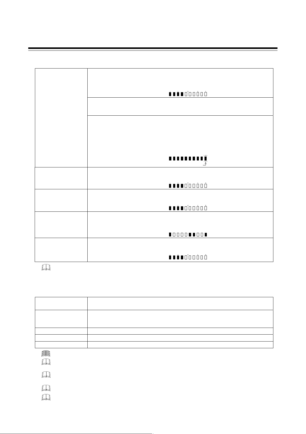
Character Symbols:
SYMBOLS
: This mark indicates precautions that must be taken if there is danger of electric
shock, fire, etc., which could result in loss of life or injury.
: This mark indicates that if these precautions and operating procedures are not
taken, damage to the instrument may result.
: This mark indicates that all precautions should be taken for safe usage.
: This mark indicates important information on installation, handling and operating
procedures.
: This mark indicates supplemental information on installation, handling and
operating procedures.
0 1 2 3 4 5 6 7 8 9
Minus Period
A B (b) C c D (d) E F G H I J K
L M N (n) O (o) P Q (q) R (r) S T t U u
V W X Y Z
Degree
/
Dash
Dim lighting
Bright lighting
Flashing
IMR01W16-E7
i-3
Page 6

DOCUMENT CONFIGURATION
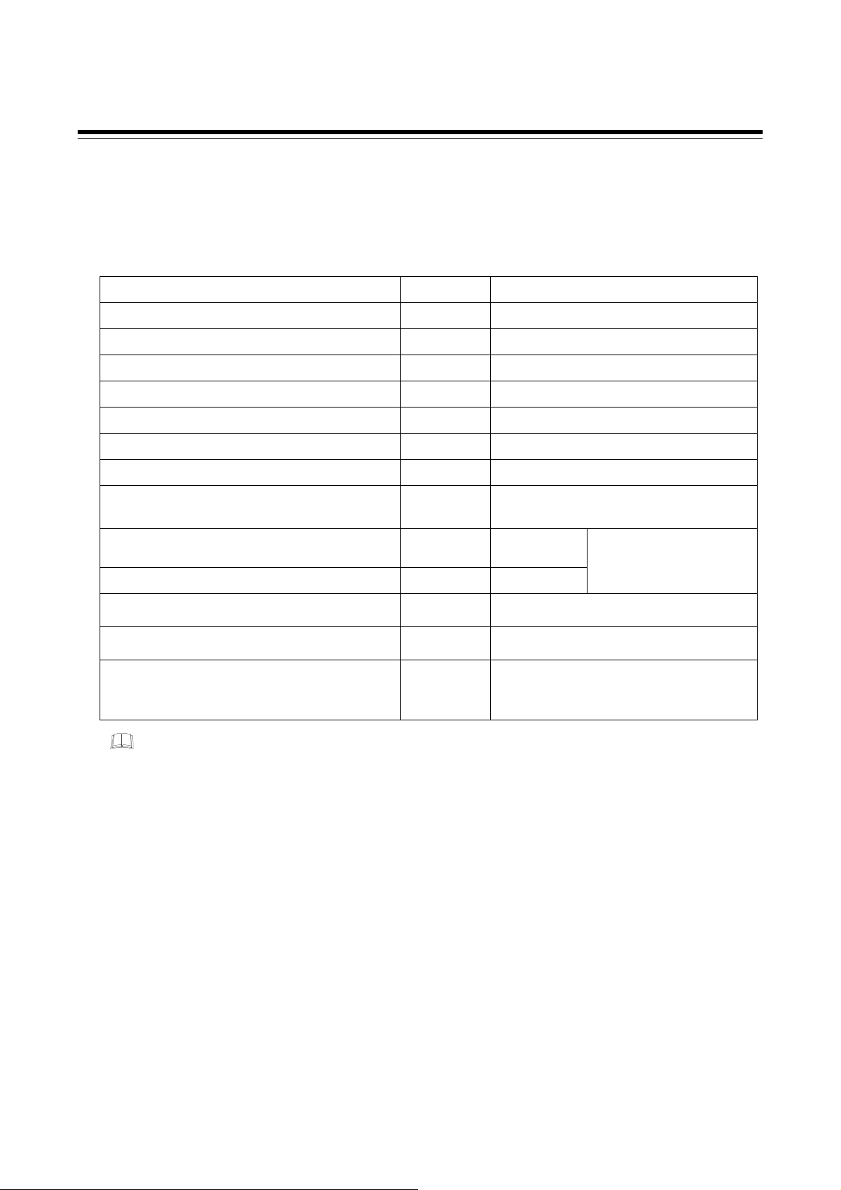
There are six manuals pertaining to this product. Please be sure to read all manuals specific to your
application requirements. If you do not have a necessary manual, please contact RKC sales office, the
agent, or download from the official RKC website.
The following manuals can be downloaded from the official RKC website:
http://www.rkcinst.com/english/manual_load.htm.
Manual Manual Number Remarks
FB100 Installation Manual IMR01W12-E
FB100 Quick Operation Manual
FB100 Parameter List
FB100 Communication Quick Manual
FB100 Instruction Manual IMR01W16-E7
FB100/FB400/FB900
Communication Instruction Manual *
* Sold separately
IMR01W13-E
IMR01W14-E
IMR01W15-E
IMR01W04-E
Read this manual carefully before operating the instrument. Please place the manual in a
convenient location for easy reference.
This manual is enclosed with instrument.
This manual explains the mounting and wiring,
front panel name, and the operation mode
outline.
This manual is enclosed with instrument.
This manual explains the basic key operation,
mode menu, and data setting.
This manual is enclosed with instrument.
This list is a compilation of the parameter data
of each mode.
This manual is enclosed with instrument.
(Only FB100 provided with the communication
function)
This manual explains the connection method
with host computer, communication
parameters, and communication data (except
for parameters in Engineering Mode).
This Manual.
This manual explains the method of
the mounting and wiring, the operation of
various functions, and troubleshooting.
This manual explains RKC communication
protocol (ANSI X3.28-1976), Modbus, and
relating to the communication parameters
setting.
i-4
IMR01W16-E7
Page 7

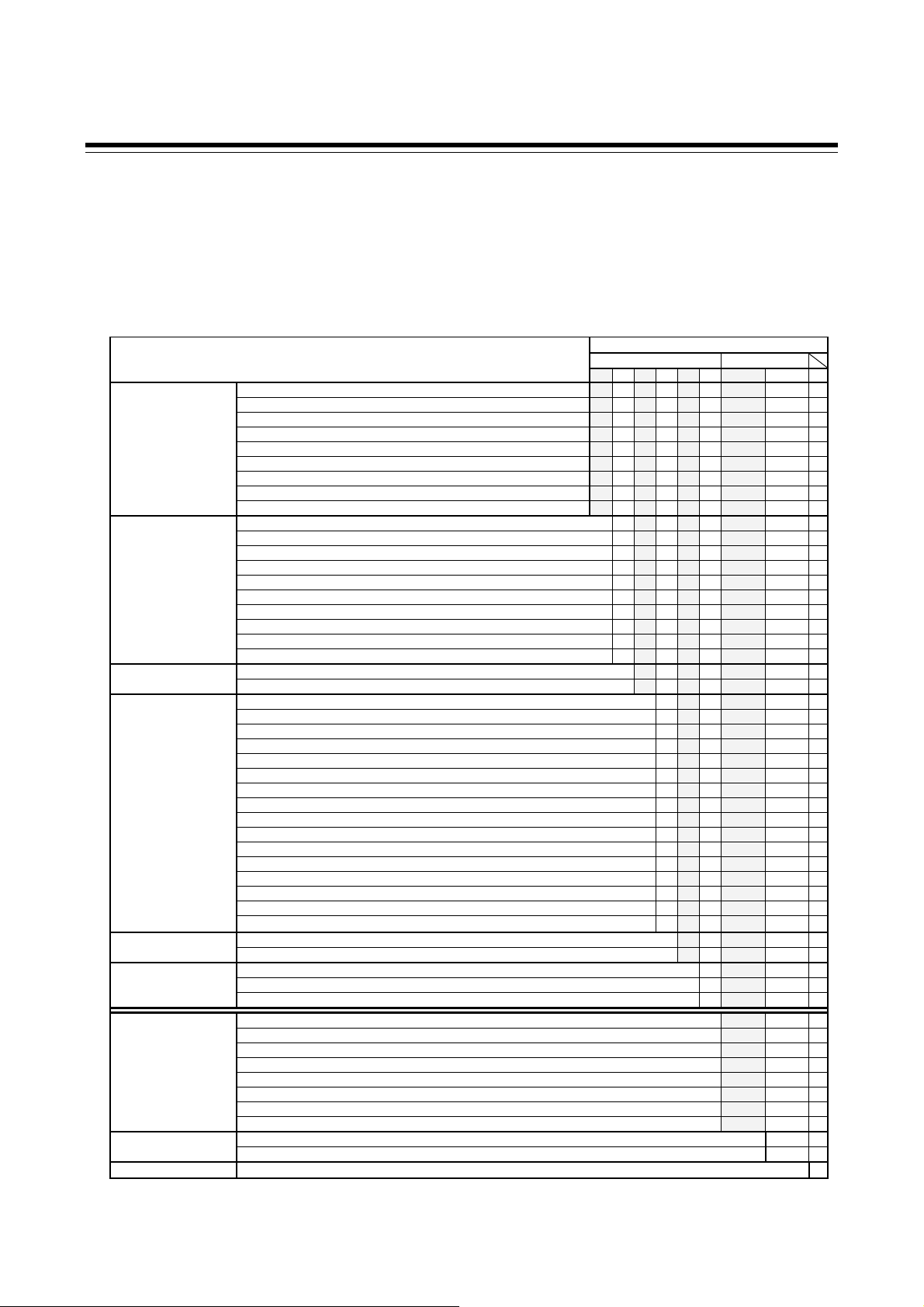
CONTENTS
1. OUTLINE ........................................................................... 1-1
1.1 Features ....................................................................................................... 1-2
1.2 Checking the Product ................................................................................... 1-3
1.3 Model Code .................................................................................................. 1-4
Suffix code .............................................................................................................. 1-4
Quick start code 2 (Initial setting code) .................................................................. 1-6
1.4 Parts Description .......................................................................................... 1-8
1.5 Input/Output Functions ............................................................................... 1-11
2. HANDLING PROCEDURE TO OPERATION .................... 2-1
Page
3. MOUNTING ........................................................................ 3-1
3.1 Mounting Cautions ........................................................................................ 3-2
3.2 Dimensions ................................................................................................... 3-3
3.3 Procedures of Mounting and Removing ....................................................... 3-4
Mounting procedures .............................................................................................. 3-4
Removing procedures ............................................................................................ 3-4
4. WIRING .............................................................................. 4-1
4.1 Wiring Cautions ............................................................................................ 4-2
4.2 Terminal Layout ............................................................................................ 4-4
Isolations of input and output.................................................................................. 4-5
4.3 Wiring of Each Terminal ............................................................................... 4-6
4.3.1 Power supply ..................................................................................................... 4-6
4.3.2 Output 1 (OUT1)/Output 2 (OUT2) .................................................................... 4-7
4.3.3 Digital output 1, 2 (DO1, DO2) .......................................................................... 4-9
4.3.4 Measured input (Thermocouple/RTD/Voltage/Current) .................................... 4-9
4.3.5 Optional ........................................................................................................... 4-10
Optional function: A [Digital input (5 points)] ..................................................... 4-10
Optional function: B [Digital input (2 points) Remote setting input (1 point)] . 4-11
Optional function: C [Digital input (2 points)
Feedback resistance input (1 point)] ................................ 4-12
Optional function: D [Digital input (2 points)
Current transformer input (2 points)] ................................ 4-13
Optional function: E [Communication (1 point) Digital input (3 points) .......... 4-14
Optional function: F [Communication (1 point) Digital input (1 point)
Current transformer input (1 point)] .................................. 4-15
Optional function: G [Communication (2 points)] .............................................. 4-16
IMR01W16-E7 i-5
Page 8

Optional function: H [Communication (1 point)
Current transformer input (2 points)] ................................ 4-17
Optional function: J [Communication (1 point) Digital input (1 point)
Remote setting input (1 point)] ......................................... 4-18
Optional function: 3, 4, 5, 6, 7, 8
[Digital input (1 point) Transmission output (1 point)
Remote setting input (1 point)] ......................................... 4-20
5. OPERATION MENU AND BASIC OPERATION ............... 5-1
5.1 Operation Menu ............................................................................................ 5-2
Input type and input range display .......................................................................... 5-3
Page
5.2 Basic Operation ............................................................................................ 5-4
5.2.1 Scrolling through parameters ............................................................................ 5-4
SV setting & monitor mode ................................................................................. 5-4
Parameter setting mode, Setup setting mode .................................................... 5-6
Operation mode .................................................................................................. 5-7
Engineering mode ............................................................................................... 5-8
5.2.2 Changing set value (SV) ................................................................................... 5-9
5.2.3 Operation of the direct key .............................................................................. 5-10
5.2.4 Data lock function ............................................................................................ 5-11
6. OPERATION ...................................................................... 6-1
6.1 Operating Precautions .................................................................................. 6-2
6.2 Monitoring Display in Operation .................................................................... 6-3
When the Direct key type is other than Monitor ...................................................... 6-3
When the Direct key type is Monitor ................................................................... 6-4
6.3 Operating Setting .......................................................................................... 6-5
6.3.1 Set the Set value (SV) ....................................................................................... 6-5
6.3.2 Set the Event set value (alarm set value) ......................................................... 6-7
6.3.3 Autotuning (AT) start ......................................................................................... 6-8
To manually set PID values ................................................................................ 6-9
6.4 RUN/STOP Transfer ................................................................................... 6-11
RUN/STOP transfer by Front key operation ......................................................... 6-11
RUN/STOP transfer by Direct key operation ........................................................ 6-12
RUN/STOP transfer by Digital input (DI) [optional] ............................................... 6-13
6.5 Autotuning (AT) .......................................................................................... 6-15
Caution for using the Autotuning (AT) .................................................................. 6-15
Requirements for Autotuning (AT) start ................................................................ 6-15
i-6 IMR01W16-E7
Page 9

Page
Requirements for Autotuning (AT) cancellation .................................................... 6-15
Autotuning (AT) start/stop operation ..................................................................... 6-16
6.6 Startup Tuning (ST) .................................................................................... 6-18
Caution for using the Startup tuning (ST) ............................................................. 6-18
Requirements for Startup tuning (ST) start ........................................................... 6-19
Requirements for Startup tuning (ST) cancellation ............................................... 6-19
Startup tuning (ST) setting .................................................................................... 6-20
6.7 Auto/Manual Transfer ................................................................................. 6-23
Auto/Manual transfer by Front key operation ....................................................... 6-24
Auto/Manual transfer by Direct key operation ...................................................... 6-25
Auto/Manual transfer by Digital input (DI) [optional] ............................................. 6-26
Procedure for setting the Manipulated output value (MV) in Manual mode .......... 6-28
6.8 Remote/Local Transfer ............................................................................... 6-29
Remote/Local transfer by Front key operation ..................................................... 6-29
Remote/Local transfer by Direct key operation .................................................... 6-30
Remote/Local transfer by Digital input (DI) [optional] ........................................... 6-31
6.9 Control Area Transfer ................................................................................. 6-33
Control area transfer by Front key operation ........................................................ 6-34
Control area transfer by Direct key operation ....................................................... 6-35
Control area transfer by Digital input (DI) [optional] ............................................. 6-36
Control area transfer by Area soak time (Ramp/Soak Control) ............................ 6-38
6.10 Interlock Release ...................................................................................... 6-39
Interlock release method by Front key operation ................................................. 6-40
Interlock release method by Digital input (DI) [optional] ....................................... 6-40
6.11 Start Action at Recovering Power Failure ................................................. 6-42
Hot/Cold start selection ........................................................................................ 6-42
Start determination point ...................................................................................... 6-42
6.12 Position Proportioning PID Control ........................................................... 6-43
Setting flowchart ................................................................................................... 6-45
Setting procedures ............................................................................................... 6-47
6.13 Ramp/Soak Control .................................................................................. 6-52
Operation flowchart .............................................................................................. 6-53
Settings before operation ..................................................................................... 6-54
Operation procedures ........................................................................................... 6-56
6.14 Group Operation by the Intercontroller Communication ........................... 6-61
6.14.1 Wiring method of the Intercontroller communication ..................................... 6-61
6.14.2 Common setting of the Intercontroller communication .................................. 6-62
6.14.3 Group RUN/STOP function ........................................................................... 6-64
IMR01W16-E7
Operation flowchart ........................................................................................... 6-64
Requirements for Group RUN/STOP ................................................................ 6-65
Group RUN/STOP operation and states ........................................................... 6-65
i-7
Page 10

Page
Settings before operation .................................................................................. 6-66
Usage example ................................................................................................. 6-69
6.14.4 Automatic temperature rise function (with learning function) ........................ 6-72
Requirements for automatic temperature rise learning start ............................. 6-73
Requirements for automatic temperature rise learning cancellation ................. 6-73
Requirements for automatic temperature rise start .......................................... 6-74
Requirements for automatic temperature rise cancellation .............................. 6-74
Operation flowchart ........................................................................................... 6-75
Settings before operation .................................................................................. 6-76
Operation procedures ....................................................................................... 6-79
6.14.5 Cascade control function ............................................................................... 6-81
Operation flowchart ........................................................................................... 6-82
Settings before operation .................................................................................. 6-83
Adjustment after control starting ....................................................................... 6-85
Operation procedures ....................................................................................... 6-88
6.14.6 Ratio setting function ..................................................................................... 6-89
Operation flowchart ........................................................................................... 6-90
Settings before operation .................................................................................. 6-91
Adjustment after control starting ....................................................................... 6-93
Operation procedures ....................................................................................... 6-96
Usage example ................................................................................................. 6-97
7. PARAMETER DESCRIPTION ........................................... 7-1
7.1 SV Setting & Monitor Mode .......................................................................... 7-2
7.1.1 Display sequence (When the Direct key type is other than Monitor) ..................... 7-2
7.1.2 Display sequence (When the Direct key type is Monitor) .................................. 7-3
7.1.3 Monitor and setting item .................................................................................... 7-4
7.2 Operation Mode .......................................................................................... 7-14
7.2.1 Display sequence ............................................................................................ 7-14
7.2.2 Operation item ................................................................................................. 7-15
7.3 Parameter Setting Mode ............................................................................. 7-22
7.3.1 Display sequence ............................................................................................ 7-23
7.3.2 Parameter setting item .................................................................................... 7-24
7.4 Setup Setting Mode .................................................................................... 7-37
7.4.1 Display sequence ............................................................................................ 7-37
7.4.2 Setup setting item ........................................................................................... 7-38
7.5 Engineering Mode ...................................................................................... 7-52
7.5.1 Display sequence ............................................................................................ 7-52
7.5.2 Precaution against parameter change ............................................................ 7-58
i-8
IMR01W16-E7
Page 11

Page
7.5.3 Engineering setting item .................................................................................. 7-65
Function block 10 (F10.) [Display] ................................................................... 7-65
Function block 11 (F11.) [Direct key] ............................................................... 7-70
Function block 21 (F21.) [Input] ....................................................................... 7-71
Function block 22 (F22.) [Remote setting input type] ...................................... 7-79
Function block 23 (F23.) [Digital input assignment] ........................................ 7-80
Function block 30 (F30.) [Output] .................................................................... 7-81
Function block 33 (F33.) [Transmission output] .............................................. 7-86
Function block 41 (F41.) [Event 1] .................................................................. 7-88
Function block 42 (F42.) [Event 2] .................................................................. 7-97
Function block 43 (F43.) [Event 3] ................................................................ 7-101
Function block 44 (F44.) [Event 4] ................................................................ 7-105
Function block 45 (F45.) [Heater break alarm 1] ........................................... 7-112
Function block 46 (F46.) [Heater break alarm 2] ........................................... 7-116
Function block 50 (F50.) [Hot/Cold start etc.] ................................................ 7-119
Function block 51 (F51.) [Control 1] .............................................................. 7-125
Function block 52 (F52.) [Control 2] .............................................................. 7-140
Function block 53 (F53.) [Position proportioning PID control] ....................... 7-152
Function block 54 (F54.) [Startup tuning] ...................................................... 7-157
Function block 55 (F55.) [Group/Automatic temperature rise] ...................... 7-159
Function block 60 (F60.) [Communication protocol] ...................................... 7-162
Function block 70 (F70.) [Time unit] .............................................................. 7-163
Function block 71 (F71.) [Setting limiter] ....................................................... 7-164
Function block 91 (F91.) [Others] .................................................................. 7-165
8. TROUBLESHOOTING ....................................................... 8-1
8.1 Error Display ................................................................................................. 8-2
Display when input error occurs ............................................................................. 8-2
Self-diagnostic error ............................................................................................... 8-3
8.2 Solutions for Problems ................................................................................. 8-4
Display .................................................................................................................... 8-5
Control .................................................................................................................... 8-6
Operation ................................................................................................................ 8-8
Event function ......................................................................................................... 8-9
Heater break alarm (HBA) .................................................................................... 8-10
9. SPECIFICATIONS ............................................................. 9-1
Measured input ................................................................................................... 9-2
Remote setting (RS) input [optional] ................................................................... 9-3
Current transformer (CT) input [optional] ............................................................ 9-4
IMR01W16-E7
i-9
Page 12

Page
Feedback resistance (FBR) input [optional] ........................................................ 9-4
Digital input (DI) [optional] .................................................................................. 9-5
Output (OUT1, OUT2) ........................................................................................ 9-5
Digital output (DO1, DO2) ................................................................................... 9-6
Transmission output (AO) [optional] ................................................................... 9-6
Performance (at the ambient temperature 23 ±2 C) .......................................... 9-7
Control ................................................................................................................ 9-8
Brilliant II PID control .......................................................................................... 9-8
Brilliant II Heat/Cool PID control ......................................................................... 9-9
Brilliant II Position proportioning PID control without FBR ................................ 9-10
Event function [optional] ................................................................................... 9-11
Control loop break alarm (LBA) [optional] ......................................................... 9-12
Heater break alarm (HBA) [time-proportional control output (optional)] ........... 9-12
Heater break alarm (HBA) [continuous control output (optional)] ..................... 9-12
Multi-memory area function [optional] ............................................................... 9-12
Loader communication ..................................................................................... 9-13
Communication [optional] ................................................................................. 9-13
Intercontroller communication function [optional] ............................................. 9-14
Self-diagnostic function ..................................................................................... 9-15
Power ................................................................................................................ 9-15
General specifications ...................................................................................... 9-16
Standard ........................................................................................................... 9-17
APPENDIX ............................................................................ A-1
A. Removing the Internal Assembly ................................................................... A-2
B. Replacing the Waterproof/Dustproof Rubber Packing ................................... A-4
C. Current Transformer (CT) Dimensions .......................................................... A-6
D. Memory Area Data List ................................................................................. A-7
E. Parameter List ............................................................................................... A-8
F. Seal [for Unit and Direct key] (accessory attached) ..................................... A-24
INDEX .................................................................................... B-1
Alphabetical Order ............................................................................................. B-2
Character Order ................................................................................................. B-5
Revisions
i-10
IMR01W16-E7
Page 13

OUTLINE
1.1 Features ........................................................................................... 1-2
1.2 Checking the Product ....................................................................... 1-3
1.3 Model Code ...................................................................................... 1-4
1.4 Parts Description .............................................................................. 1-8
1.5 Input/Output Functions ................................................................... 1-11
IMR01W16-E7 1-1
Page 14

1. OUTLINE
1.1 Features
This chapter describes features, package contents and model code, etc. The digital controller of this
high performance type has the following features:
Panel space saving: 74 mm depth
Selectable sampling time among 50ms, 100ms, and 250 ms.
Selectable sampling time makes the FB100 suitable for any application rang ing from pressure control requiring
fast response to precise control requiring highest resolution. (Factory setting: 100 ms)
Selectable PID control algorithm
PID control algorithm is selectable in the FB100 to achieve the most precise control for various applications.
PV derivative PID : suitable for fixed setpoint control (Factory setting)
Deviation derivative PID : suitable for ramp control using ramp-to-setpoint function and cascade control.
Advanced Heat/Cool PID algorithm with Undershoot Suppression
Startup tuning to eliminate time for autotuning
Mode switching can be performed directly (Direct key)
Control RUN/STOP, Auto/Manual, Remote/Local, Memory area, or monitor transfer can be selected.
(Factory set value: Auto/Manual transfer)
Up to 8 recipes (multi-memory area) or Ramp/Soak control
FB100 can store up to 8 sets of control parameters. Ramp/Soak control is available by using the memory area
function.
Easy maintenance
The internal assembly of the FB100 can be removed from the front.
NEMA4X and IP66 waterproof and dustproof protection for severe environments.
(standard)
Two communication ports (optional)
Host communication can be performed with a host computer or host device such as an operation panel.
(Communication 1)
Group operation such as cascade control and ratio setting is possible using only Intercontroller communication; it
is not necessary to use communication with a host computer or analog signals such as remote setting input and
transmission output.
(Communication 1 or Communication 2)
Easy-setup and Data Monitoring via a standard data port
The FB100 have the loader port (provided as standard) to connect to a PC USB port with Windows
2000/XP/Vista/7.
The standard port allows setup and data logging to be managed by the PC. The FB100 is recognized as an
external device on the PC.
[The communication tool (WinUCI, PROTEM2) can be downloaded from the RKC official website:
http://www.rkcinst.com/.]
1-2 IMR01W16-E7
Page 15
1. OUTLINE
1.2 Checking the Product
Before using this product, check each of the following:
Model code
Check that there are no scratches or breakage in external appearance (case, front panel, or terminal, etc.)
Check that all of the items delivered are complete. (Refer to below)
Accessories Q’TY Remarks
Instrument 1
Mounting brackets (with screw) 2
Seal (SAP-379) 1
Case rubber packing (KRB100-39) 1 For waterproof/dustproof
Installation Manual (IMR01W12-E) 1 Enclosed with instrument
Quick Operation Manual (IMR01W13-E) 1 Enclosed with instrument
Parameter List (IMR01W14-E) 1 Enclosed with instrument
Communication Quick Manual (IMR01W15-E) 1 Enclosed with instrument
(with communication function )
Instruction Manual (IMR01W16-E7) 1
Communication Instruction Manual (IMR01W04-E) 1 Sold separately
Terminal cover (KCA100-517)
Front cover (KRB100-36A)
Current transformer
(CTL-6-P-N [for 0 to 30 A] or
CTL-12-S56-10L-N [for 0 to 100 A])
Depending on the
order quantity
Depending on the
order quantity
Depending on the
order quantity
This manual
(sold separately)
Optional (sold separately)
Optional (sold separately)
Optional (sold separately)
This manual can be downloaded
from the official RKC website:
http://www.rkcinst.com/english/
manual_load.htm.
ローダツール操作説明書 (IMR01W05-J)
If any of the products are missing, damaged, or if your manual is incomplete, please contact
RKC sales office or the agent.
1
別売り
IMR01W16-E7 1-3
Page 16
1. OUTLINE
1.3 Model Code
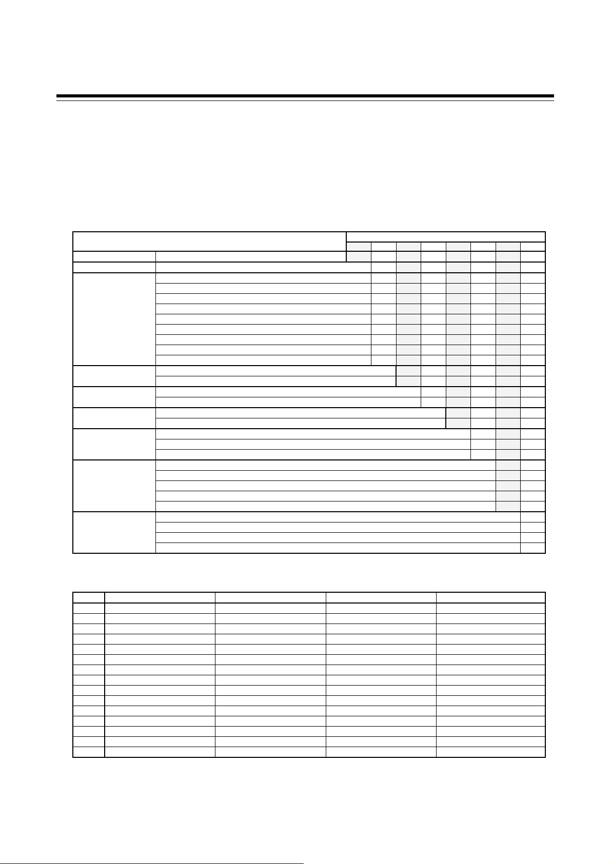
Check that the product received is correctly specified by referring to the following model code list:
If the product is not identical to the specifications, please contact RKC sales office or the agent.
Suffix code
FB100-□ □-□*□ / □ □-□ □□□ /Y
(1) (2) (3) (4) (5) (6) (7) (8) (9)
(1) (2) (3) (4) (5) (6) (7) (8) (9)
Relay contact output M
Voltage pulse output V
Voltage output (0 to 5 V DC) 4
Voltage output (0 to 10 V DC) 5
Output 1 (OUT1)
Output 2 (OUT2)
Power supply voltage
Optional function
Case color
Quick start code
Control Method
[Quick start code 1]
Measured input and Range
[Quick start code 1]
Instrument specification
*
When the optional function code "G" is selected, the factory set value of Communication 2 becomes Intercontroller communication.
Voltage output (1 to 5 V DC) 6
Current output (0 to 20 mA DC) 7
Current output (4 to 20 mA DC) 8
Triac output T
Open collector output D
None N
Relay contact output M
Voltage pulse output V
Voltage output (0 to 5 V DC) 4
Voltage output (0 to 10 V DC) 5
Voltage output (1 to 5 V DC) 6
Current output (0 to 20 mA DC) 7
Current output (4 to 20 mA DC) 8
Triac output T
Open collector output D
24 V AC/DC 3
100 to 240 V AC 4
None N
Digital input (5 points) A
Digital input (2 points) Remote setting input B
Digital input (2 points) Feedback resistance input C
Digital input (2 points) CT input (2 points) D
Digital input (3 points) Communication (1 point) E
Digital input (1 point) Communication (1 point) CT input (1 point) F
Communication (2 points) * G
Communication (1 point) CT input (2 points) H
Communication (1 point) Digital input (1 point) Remote setting input J
Digital input (1 point) Remote setting input Transmission output [Voltage output (0 to 1 V DC) 3
Digital input (1 point) Remote setting input Transmission output [Voltage output (0 to 5 V DC) 4
Digital input (1 point) Remote setting input Transmission output [Voltage output (0 to 10 V DC) 5
Digital input (1 point) Remote setting input Transmission output [Voltage output (1 to 5 V DC) 6
Digital input (1 point) Remote setting input Transmission output [Current output (0 to 20 mA DC) 7
Digital input (1 point) Remote setting input Transmission output [Current output (4 to 20 mA DC) 8
White case N
Black case A
No quick start code (Configured to factory set value) N
Specify quick start code 1 1
Specify quick start code 1 and 2 (Refer to page 1-6) 2
Quick start code 1 is not specified No code
PID control with AT (Reverse action) F
PID control with AT (Direct action) D
Heat/Cool PID control with AT G
Heat/Cool PID control with AT (for Extruder [air cooling]) A
Heat/Cool PID control with AT (for Extruder [water cooling]) W
Position proportioning PID control without FBR (Reverse action) Z
Position proportioning PID control without FBR (Direct action) C
Quick start code 1 is not specified No code
Refer to Range Code Table.
Version symbol Y
Suffix code
Specifications
Hardware coding only Quick start code 1
1-4 IMR01W16-E7
Page 17

Range Code Table
[Thermocouple (TC) input, RTD input] [Voltage input, Current input]
Type Code Measured range Code Measured range Type Code Measured range
K35 200.0 to 400.0 C KC4 328.0 to 400.0 F 0 to 10 mV DC 101
K40 200.0 to 800.0 C KC6 250.0 to 800.0 F 0 to 100 mV DC 201
K41 200 to 1372 C KC5 328 to 2502 F 0 to 1 V DC 301
K K09 0.0 to 400.0 C KA4 0.0 to 800.0 F 0 to 5 V DC 401 Programmable range
K10 0.0 to 800.0 C KA1 0 to 800 F 0 to 10 V DC 501 19999 to 19999
K14 0 to 300 C KA2 0 to 1600 F 1 to 5 V DC 601 [The decimal point position is selectable]
K02 0 to 400 C 0 to 20 mA DC 701 (Factory set value: 0.0 to 100.0)
K04 0 to 800 C 4 to 20 mA DC 801
J27 200.0 to 400.0 C JC6 328.0 to 1200.0 F 100 to 100 mV DC 901
J32 200.0 to 800.0 C JC7 200.0 to 700.0 F 1 to 1 V DC 902
J15 200 to 1200 C JB9 328 to 2192 F 10 to 10 mV DC 903
J J08 0.0 to 400.0 C JB6 0.0 to 800.0 F
J09 0.0 to 800.0 C JA1 0 to 800 F
J02 0 to 400 C JA2 0 to 1600 F
J04 0 to 800 C
T T19 200.0 to 400.0 C TC2 328.0 to 752.0 F
E E21 200.0 to 700.0 C EA9 328.0 to 1292.0 F
E06 200 to 1000 C EB1 328 to 1832 F
S S06 50 to 1768 C SA7 58 to 3214 F
R R07 50 to 1768 C RA7 58 to 3214 F
B B03 0 to 1800 C BB2 0 to 3272 F
N N02 0 to 1300 C NA7 0 to 3272 F
PLII A02 0 to 1390 C AA2 0 to 2534 F
W5Re/W26Re W03 0 to 2300 C WA2 0 to 4200 F
U U04 0.0 to 600.0 C UB2 32.0 to 1112.0 F
L L04 0.0 to 900.0 C LA9 32.0 to 1652.0 F
Pt100 D34 100.00 to 100.00 C DD1 200.0 to 200.0 F
D21 200.0 to 200.0 C DC8 199.99 to 199.99 F
D35 200.0 to 850.0 C DC9 328.0 to 1562.0 F
JPt100 P29 100.00 to 100.00 C PC8 199.99 to 199.99 F
P30 200.0 to 640.0 C PC9 328.0 to 1184.0 F
PD1 200.0 to 200.0 F
1.3 Model Code
IMR01W16-E7
1-5
Page 18
1.3 Model Code
Quick start code 2 (Initial setting code)
Quick start code 2 tells the factory to ship with each parameter preset to the values detailed as
specified by the customer. Quick start code is not necessarily specified when ordering, unless the
preset is requested. These parameters are software selectable items and can be re-programmed in the
field via the manual.
□□ □□ □-□ □ □ □-□ □
(1) (2) (3) (4) (5) (6) (7) (8) (9)
Specifications
Output assignment OUT1, OUT2, DO1, DO2 (Refer to Output Assignment Code Table)
Digital input assignment DI1 to DI5 (Refer to Digital Input Assignment Code Table)
None N
Voltage input (0 to 10 mV DC) 1
Voltage input (0 to 100 mV DC) 2
Voltage input (0 to 1 V DC) 3
Remote setting input
Event function 1 (EV1)
Event function 2 (EV2)
Event function 3 (EV3)
Event function 4 (EV4)
CT type 1
Communication 1 protocol
1
If the CT type is not specified, the instrument is shipped with the CT input setting of “CTL-6-P-N.”
2
Selectable in the case of optional function codes E, F, H, and J.
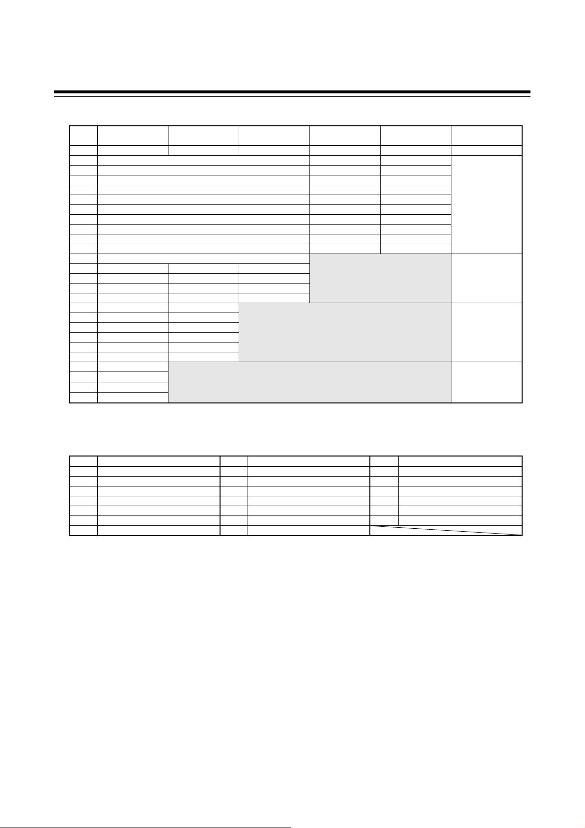
Output Assignment Code Table
Code Output 1 (OUT1) Output 2 (OUT2) Digital output 1 (DO1) Digital output 2 (DO2)
01 Control output 1 Control output 2 Event output 1 (EV1) Event output 2 (EV2)
02 Control output 1 Control output 2 Event output 1 (EV1) Event output 4 (EV4)
03 Control output 1 Control output 2 Event output 1 (EV1) Heater break alarm (HBA) output
04 Control output 1 Control output 2 Event output 1 (EV1) FAIL output (De-energized)
05 Control output 1 Control output 2 Event output 4 (EV4) Heater break alarm (HBA) output
06 Control output 1 Control output 2 Event output 4 (EV4) FAIL output (De-energized)
07 Control output 1 Control output 2 Heater break alarm (HBA) output FAIL output (De-energized)
08 Control output 1 Heater break alarm (HBA) output Event output 1 (EV1) Event output 2 (EV2)
09 Control output 1 Heater break alarm (HBA) output Event output 1 (EV1) Event output 4 (EV4)
10 Control output 1 Heater break alarm (HBA) output Event output 1 (EV1) FAIL output (De-energized)
11 Control output 1 Heater break alarm (HBA) output Event output 4 (EV4) FAIL output (De-energized)
12 Control output 1 FAIL output (De-energized) Event output 1 (EV1) Event output 2 (EV2)
13 Control output 1 FAIL output (De-energized) Event output 1 (EV1) Event output 4 (EV4)
14 Control output 1 Event output 1 (EV1) Event output 2 (EV2) Event output 3 (EV3)
15 Control output 1 Event output 4 (EV4) Event output 1 (EV1) Event output 2 (EV2)
Energized/De-energized is configurable except for the FAIL output. (Factory shipment: Energized)
When Current transformer (CT) input is two-point input, Heater break alarm (HBA) output is OR output.
Invalid for a non-existing output/event function.
When used as Heat/Cool PID control, select any code of 1 to 7.
For Position proportioning PID control, output 1 (OUT1) is open-side output and output 2 (OUT2) is close-side output, regardless of the above selection.
Voltage input (0 to 5 V DC) 4
Voltage input (0 to 10 V DC) 5
Voltage input (1 to 5 V DC) 6
Current input (0 to 20 mA DC) 7
Current input (4 to 20 mA DC) 8
None N
Refer to Event Type Code Table
None N
Refer to Event Type Code Table
None N
Refer to Event Type Code Table
None N
Refer to Event Type Code Table
Control loop break alarm (LBA) 5
CT1 (none), CT2 (none) N
CT1 (CTL-6-P-N), CT2 (none) P
CT1 (CTL-12-S56-10L-N), CT2 (none) S
CT1 (CTL-6-P-N), CT2 (CTL-6-P-N) T
CT1 (CTL-12-S56-10L-N), CT2 (CTL-12-S56-10L-N) U
None N
RKC communication (ANSI X3.28-1976) 1
Modbus 2
Intercontroller communication 2 A
Quick start code 2 (Initial setting code)
(1) (2) (3) (4) (5) (6) (7) (8)
1-6
IMR01W16-E7
Page 19
Digital Input Assignment Code Table
Code
01 Unused Unused Unused Unused Unused
02 Memory area number selection (1 to 8) Memory area set RUN/STOP transfer
03 Memory area number selection (1 to 8) Memory area set Unused
04 Memory area number selection (1 to 8) Memory area set Auto/Manual transfer
05 Memory area number selection (1 to 8) Memory area set Interlock release
06 Memory area number selection (1 to 8) RUN/STOP transfer Unused
07 Memory area number selection (1 to 8) RUN/STOP transfer Auto/Manual transfer
08 Memory area number selection (1 to 8) RUN/STOP transfer Interlock release
09 Memory area number selection (1 to 8) Unused Auto/Manual transfer
10 Memory area number selection (1 to 8) Unused Interlock release
11 Memory area number selection (1 to 8) Auto/Manual transfer Interlock release
12 Memory area number selection (1 to 8)
13 RUN/STOP transfer Remote/Local transfer * Auto/Manual transfer
14 RUN/STOP transfer Remote/Local transfer * Interlock release
15 RUN/STOP transfer Auto/Manual transfer Interlock release
16 Remote/Local trans fer * Auto/Manual transfer Interlock release
17 RUN/STOP transfer Remote/Local transfer *
18 RUN/STOP transfer Auto/Manual transfer
19 RUN/STOP transfer Interlock release
20 Remote/Local trans fer * Auto/Manual transfer
21 Remote/Local tr ansfer * Interlock release
22 Auto/Manual transfer Interlock release
23 RUN/STOP transfer
24 Remote/Local tr ans fer *
25 Auto/Manual transfer
26 Interlock release
Memory area set: Switches to the memory area specified in DI1 – DI3 when the contact goes from open to closed.
Digital input 1
(DI1)
* When the optional function code A, C or D is selected, the Remote/Local transfer is invalid.
Digital input 2
(DI2)
Digital input 3
(DI3)
Digital input 4
(DI4)
Digital input 5
(DI5)
1.3 Model Code
Selectable
Optional function
A
A, E
A, B, C, D, E
A, B, C, D, E, F, J,
3, 4, 5, 6, 7, 8
Event Type Code Table
Code Type Code Type Code Type
A Deviation high H Process high V SV high
B Deviation low J Process low W SV low
C Deviation high/low K Process high with hold action 1 MV1 high [heat-side]
D Band L Process low with hold action 2 MV1 low [heat-side]
E Deviation high with hold action Q Deviation high with re-hold action 3 MV2 high [cool-side]
F Deviation low with hold action R Deviation low with re-hold action 4 MV2 low [cool-side]
G Deviation high/low with hold action T Deviation high/low with re-hold action
IMR01W16-E7
1-7
Page 20

1. OUTLINE
A
A
y
y
1.4 Parts Description
This section describes various display units and the key functions.
Front Panel View
Manual (MAN) mode lamp (Green)
Measured value (PV)
display
Memory area display
Manipulated output (MV)
lamp (Green)
Direct keys
Set (SET) ke
Shift ke
Display units
Measured value (PV) display [Green] Displays Measured value (PV) or various parameters’ symbols.
Remote (REM) mode lamp (Green)
utotuning (AT) lamp (Green)
Set value (SV) display
Output (OUT1, OUT2) lamp (Green)
Digital output (DO1, DO2) lamp (Green)
larm (ALM) lamp (Red)
Bar graph display
Up key
Down key
Set value (SV) display [Orange]
Memory area display [Orange] Displays memory area number (1 to 8).
Displays Set value (SV), Manipulated output value (MV) or various
parameters’ set values.
Indication lamps
Manual (MAN) mod e lamp [Green] Lights when operated in manual mode.
Remote (REM) mode lamp [Green] Lights when operated in remote mode.
Autotuning (AT) lamp [Green]
Manipulated output (MV) lamp [Green]
Output (OUT1, OUT2) lamp [Green] Lights when the output corresponding to each lamp is ON.
Digital output (DO1, DO2) lamp [Green] Lights when the output corresponding to each lamp is ON.
Alarm (ALM) lamp [Red]
These lamps work with event outputs (event function, HBA function, LBA function) which are assigned to OUT, DO
and ALM.
Flashes when Autotuning is activated.
(After autotuning is completed: AT lamp will go out)
Lights when operated in Manual mode. In this case, the Set value (SV) display
shows the Manipulated output value (MV).
Lamp indication becomes as follows for current output or voltage output:
For an output of less than 0 %: Extinguished
For an output of more than 0 % but less than 100 %: Dimly lit
For an output of more than 100 %: Lit
Lights when alarm (Event or Heater break alarm [HBA]) is turned ON.
The type of alarm which is on can be checked on the event monitor screen.
1-8 IMR01W16-E7
Page 21
0
Bar graph display [Green]
Manipulated output
values (MV1, MV2)
[Factory set value]
Heat/Cool PID control:
Position proportioning PID control:
Measured value (PV)
Displays the Manipulated output value (MV) [In the case of Position proportioning PID control,
refer to below.]. When Manipulated output value (MV) is at 0 % or less, the left-end dot of the
bar-graph flashes. When MV exceeds 100 %, the right-end dot flashes.
When both OUT1 and OUT2 light, this means overlapping, but in this case the bar graph
displays only the Manipulated output value (MV1) [heat-side].
[With FBR input]
Displays the FBR input value (0.0 to 100.0 %).
[Without FBR input]
Cannot be used as a bar graph. The bar graph displays the over-scaled state (an output of more
than 100 %). In this case, it is recommended to be set to “No display.”
Displays the Measured value (PV). Scaling is available within the input range (Input scale low to
Input scale high).
[Example]
[Example]
[Example]
050
050
Flashing
050
1.4 Parts Description
100
100
100
Set value (SV) monitor
Displays the Set value (SV). Scaling is available within the input range (Input scale low to Input
scale high). Remote mode: Displays the remote setting value.
100
Deviation value
[Example]
050
Displays the deviation between the Measured value (PV) and the Set value (SV). When the
Deviation display is selected, the dots at both ends of bar-graph light. A display resolution per
dot is settable. (Bar graph display resolution: Refer to P. 7-68)
[Example]
Current transformer 1
(CT1) input value
Current transformer 2
(CT2) input value
Displays the input value (current value) of CT1 or CT2. (Unit: A)
A display resolution per dot is settable. (Bar graph display resolution: Refer to P. 7-68)
[Example]
050
100
The factory set value of the bar graph is “Manipulated output value.” Bar graph display type can be changed by the
bar graph in the Engineering mode. (Refer to P. 7-66)
Direct keys
Pressing a direct key causes one of the operation changes below.
Auto/Manual transfer
[Factory set value]
Monitor
Memory area transfer Pressing the direct key changes to Memory area transfer screen.
Remote/Local transfer Switching the Remote/Local control mode between Remote mode and Local mode.
RUN/STOP transfer Switching the RUN/STOP mode between RUN and STOP status.
To avoid damage to the instrument, never use a sharp object to press keys.
The factory default setting is Auto/Manual transfer. The Direct key type can be set in “Direct key type” (P. 7-70)
of Engineering mode.
When the Direct key type is “Monitor”, the display of SV setting & monitor mode and the Direct key display are
different from the other types. (Refer to P. 5-4)
Use/Unused of Direct key functions is programmable. (Refer to P. 7-70)
To prevent operator error, a Direct key cannot be operated in positioning adjustment (automatic adjustment).
Switching the Auto/Manual control mode between Auto mode and Manual mode.
Use to switch the monitor screen. Pressing the direct key while any screen other than the SV
setting & monitor mode screen is being displayed returns to the Measured value (PV)/Set value
(SV) monitor screen.
IMR01W16-E7
1-9
Page 22

1.4 Parts Description
Operation keys
Set (SET) key Used for parameter calling up and set value registration.
Shift key Shift digits when settings are changed. Used to selection operation between modes.
Down key
Up key
To avoid damage to the instrument, never use a sharp object to press keys.
Bottom View
Use our communication converter COM-K (sold separately) to connect FB100 and personal
computer. Then, the cable (cable length: 1.5 meters) for connection between FB100 and our
communication converter COM-K is optional.
Side view
Decrease numerals.
Keeping pressing the DOWN key makes numeric value change faster. (Manual mode)
Increase numerals.
Keeping pressing the UP key makes numeric value change faster. (Manual mode)
Loader communication connector (Standard equipment)
1-10
Input select switch
Dip switch is used for the switching of the measured input type and
the remote setting input type.
Current input,
Voltage (low) input
To change the input type, refer to Input type (P. 7-71), Remote setting input type (P. 7-79)
For the remote setting input
For the measured input
Voltage (high) input
in the Engineering mode.
IMR01W16-E7
Page 23
1. OUTLINE
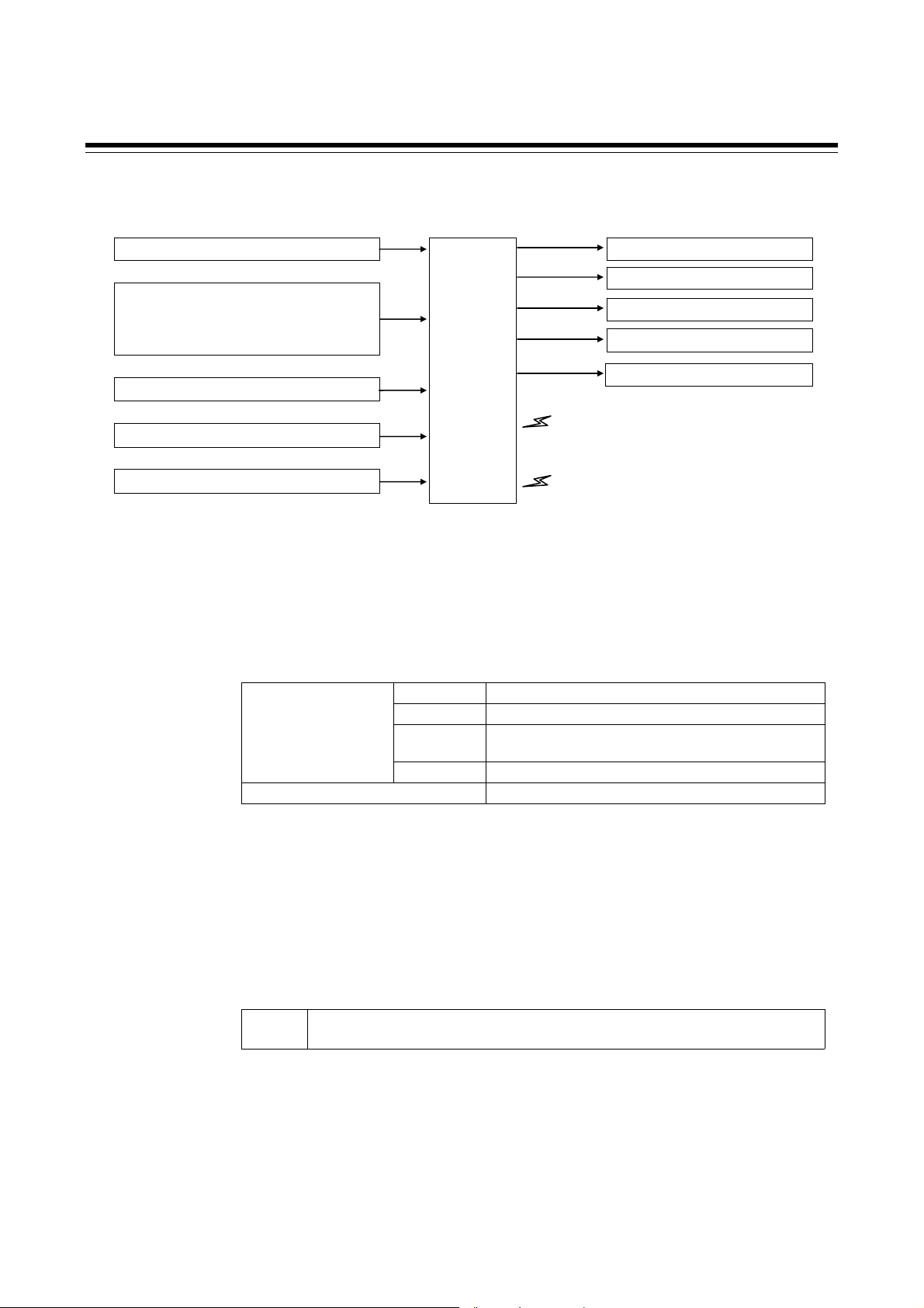
1.5 Input/Output Functions
This section describes the Input/Output functions of the instrument. To learn how to set each function,
refer to the respective page.
Measured input
Digital input DI1 to DI5 [optional]
(Memory area selection, Area set, RUN/STOP,
Remote/Local transfer, Auto/Manual transfer,
Interlock release)
Remote setting (RS) input [optional]
Current transformer (CT) input [optional]
Feedback resistance (FBR) input [optional]
Control
section
COM1 (RKC communication, Modbus, Intercontroller
COM2 (Intercontroller communication) [optional]
Loader communication
Control output 1 (Heat-side/Open-side)
Control output 2 (Cool-side/Close-side)
Output of event function
Heater break alarm output
Transmission output (AO) [optional]
communication *) [optional]
* Can only be selected when one-point
communication is used on the FB100.
Input On the FB100, Measured input, Digital input (DI), Remote setting (RS) input,
Current transformer (CT) input, and Feedback resistance (FBR) input can be used.
Measured input [universal input]:
Input groups available for measured inputs are shown in the table below. (P. 7-71)
Thermocouple K, J, E, T, S, R, B, N, PLII, W5Re/W26Re, U, L
Voltage (low) input
group
Voltage (high) input group
[Factory set value: Thermocouple K (When quick start code “N” is specified)
RTD Pt100, JPt100
Voltage (low) 0 to 1 V DC, 0 to 100 mV DC, 0 to 10 mV DC,
100 to 100 mV DC, 10 to 10 mV DC
Current 0 to 20 mA DC, 4 to 20 mA DC
1 to 1 V DC, 0 to 5 V DC, 1 to 5 V DC, 0 to 10 V DC
When the input type is changed, be sure to check the details of setting of the input
group transfer and the input type selection by the input select switch. (P. 7-71)
Digital input [DI1 to DI5] (optional)
Digital input (contact input signal from the external devices) can be used for the
following functions.
DI1 to 5
Memory area selection (number of area: 1 to 8) Area set, RUN/STOP, Remote/Local
transfer, Auto/Manual transfer, Interlock release
For function assignment to the digital input, set the Digital input (DI) assignment
(P. 7-80) in the Engineering mode.
IMR01W16-E7 1-11
Page 24

1.5 Input/Output Functions
Remote setting (RS) input [universal input] (optional)
Remote input is to change a control set point by using current or voltage input from
an external device.
Measured input is not isolated from Remote setting (RS) input.
Input groups available for Remote setting (RS) inputs are shown in the table below.
(P. 7-79)
Voltage (low) input and Current input
group
Voltage (low) input group
[Factory set value: Depend on model code]
0 to 100 mV DC, 0 to 10 mV DC, 0 to 1 V DC
0 to 20 mA DC, 4 to 20 mA DC
0 to 5 V DC, 1 to 5 V DC, 0 to 10 V DC
When using the Intercontroller communication (only slave controller of cascade
control and ratio setting), the Remote setting (RS) input function becomes invalid.
Current transformer (CT) input (optional)
CT input is used for Heater break alarm function to detect a heater break or
short-circuit.
Up to two CT inputs can be selected. (Specify when ordering)
Two types of CT available.
CTL-6-P-N (for 0 to 30 A)
CTL-12-S56-10L-N (for 0 to 100 A)
Measured input is not isolated from CT input.
If there is CT input, power frequency is automatically set by the power frequency
detection function. However, no frequency may be able to be detected if at a CT
value of less than 0.5 A.
Feedback resistance (FBR) input (optional)
When the control type is the Position proportioning PID control (with FBR input),
a valve position from the control motor can be inputted to feedback resistance.
Measured input is not isolated from Feedback resistance (FBR) input.
Feedback resistance (FBR) input cannot be used with Current transformer (CT)
input, Remote setting (RS) input and communication.
1-12
IMR01W16-E7
Page 25
1.5 Input/Output Functions
Output Up to five outputs are available. They may be used as Control output
(OUT), Digital output (DO) or Transmission output (AO) by specifying
the output type or by activating the output assignment function.
Output 1 (OUT1), Output 2 (OUT2)
The following output functions can be assigned to OUT1 and/or OUT2 at the
output assignment of the Engineering mode (P. 7-82):
- Control output,
- Heater break alarm output, or
- FAIL (De-energized fixed: contact opens under FAIL)
For Heat/Cool PID control, OUT1 corresponds to the heat-side output and OUT2
corresponds to the cool-side output.
For Position proportioning PID control, OUT1 corresponds to the open-side output
and OUT2 corresponds to the close-side output.
Output types available for OUT1 and OUT2 are shown in the table below.
(Specify when ordering)
Relay contact output 250 V AC 3 A (Resistive load), 30 V DC 1 A (Resistive load), 1a contact
Voltage pulse output 0/12 V DC (Allowable load resistance: 600 or more)
Voltage output 0 to 5 V DC, 1 to 5 V DC, 0 to 10 V DC (Allowable load resistance: 1 k or more)
Current output 0 to 20 mA DC, 4 to 20 mA DC (Allowable load resistance: 600 or less)
Triac output 0.5 A (Allowable load current)
Open collector output 30 V DC or less, 100 mA (Allowable load current), Sink type
There is not isolation between OUT1 and OUT2.
When OUT1 and OUT2 can be used for relay contact output or triac output, there
is isolation between each output (OUT1, OUT2, AO).
Digital output 1, 2 (DO1, DO2)
The following output functions can be assigned to DO1 through DO4 at the output
assignment of the Engineering mode (P. 7-82):
- Output of event function,
- Heater break alarm output, or
- FAIL (De-energized fixed: contact opens under FAIL)
The output type for DO1 and DO2 is relay only. (Specify when ordering)
Relay contact output 250 V AC 1 A (Resistive load), 30 V DC 1 A (Resistive load), 1a contact
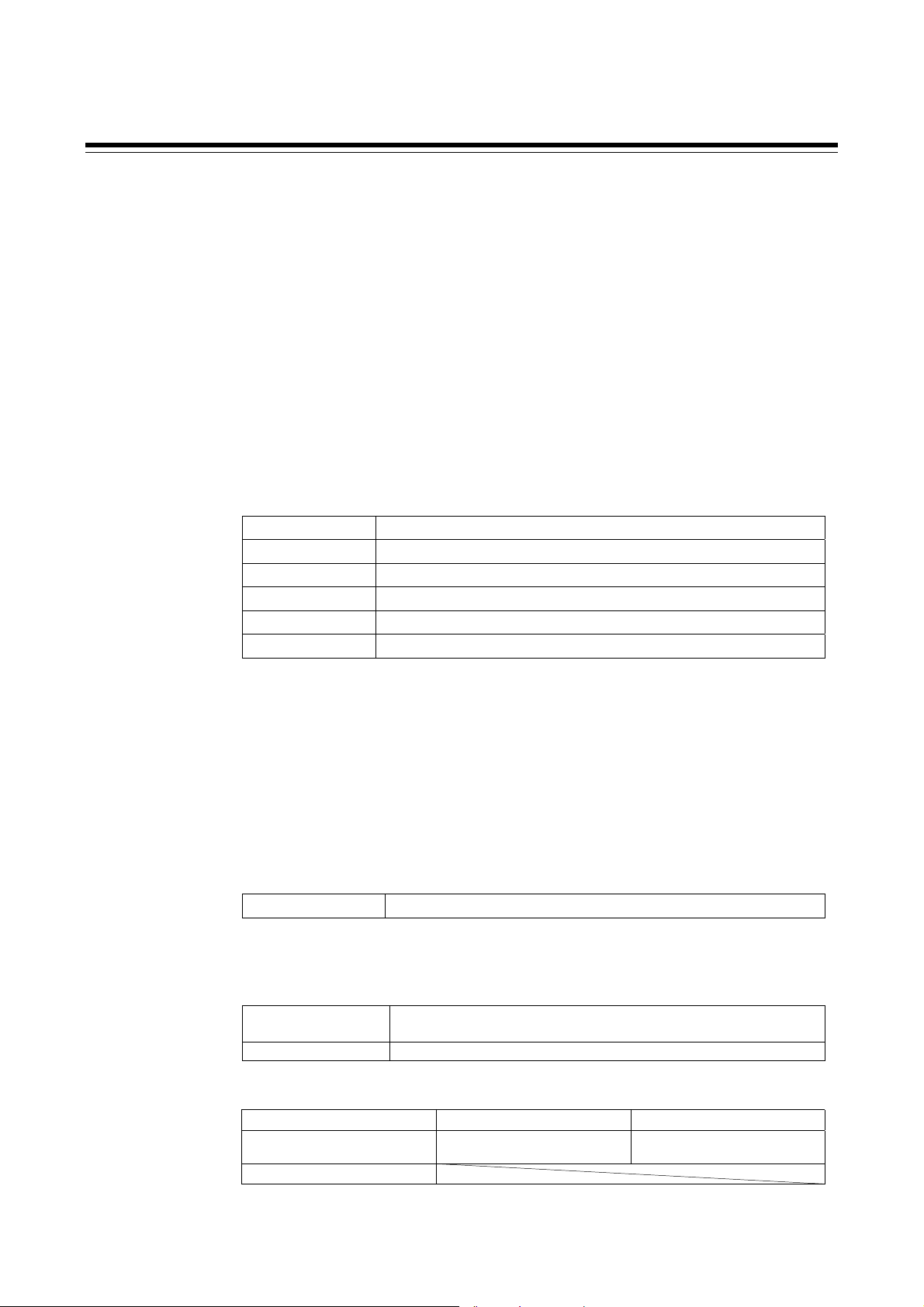
Transmission output (AO) [optional]
Output types available for transmission output are shown in the table below.
(Specify when ordering)
Voltage output 0 to 1 V DC, 0 to 5 V DC, 1 to 5 V DC, 0 to 10 V DC
Current output 0 to 20 mA DC, 4 to 20 mA DC (Allowable load resistance: 600 or less)
Parameter values shown in the following table can be output by Transmission
output (P. 7-86). These transmission output data can be output after being scaled.
Measured value (PV) Set value (SV) monitor Deviation value
Manipulated output value (MV1)
[heat-side]
Remote setting (RS) input value
Number of output: 1 point
(Allowable load resistance: 1 k or more)
Manipulated output value (MV2)
[cool-side]
Set value (SV)
IMR01W16-E7
1-13
Page 26
1.5 Input/Output Functions
Communication
Communication 1 (optional)
In this case of one-point communication, Host communication or Intercontroller
communication can be selected. (This can be specified when the order is placed.)
In this case of two-point communication, this will be for Host communication.
Communication protocol is used for RKC communication (ANSI X3.28-1976) or
Modbus. (Specify when ordering)
With Intercontroller communication, data can be exchanged between multiple
FB100/400/900 instruments without using analog signals such as Remote setting
input or Transmission output, or communication with a host computer. (Refer to
P. 6-61)
Communication Interface:
The following four functions become usable when the Intercontroller
communication is used.
Automatic temperature rise function (with learning function)
Cascade control function
Ratio setting function
Group RUN/STOP function
For details of the Host communication, refer to the separate FB100/FB400/
FB900 Communication Instruction Manual (IMR01W04-E).
Communication 2 (optional)
This can be used only for two-point communication.
Communication 2 (COM2) is used for the Intercontroller communication. Data can
be exchanged between two or more FB100s/400s/900s without using
communication with analog signals such as Remote setting input and Analog
output as well as with the host computer. (Refer to P. 6-61.)
Interface: RS-485 only
The following four functions become usable when the Intercontroller
communication is used.
Automatic temperature rise function (with learning function)
Cascade control function
Ratio setting function
Group RUN/STOP function
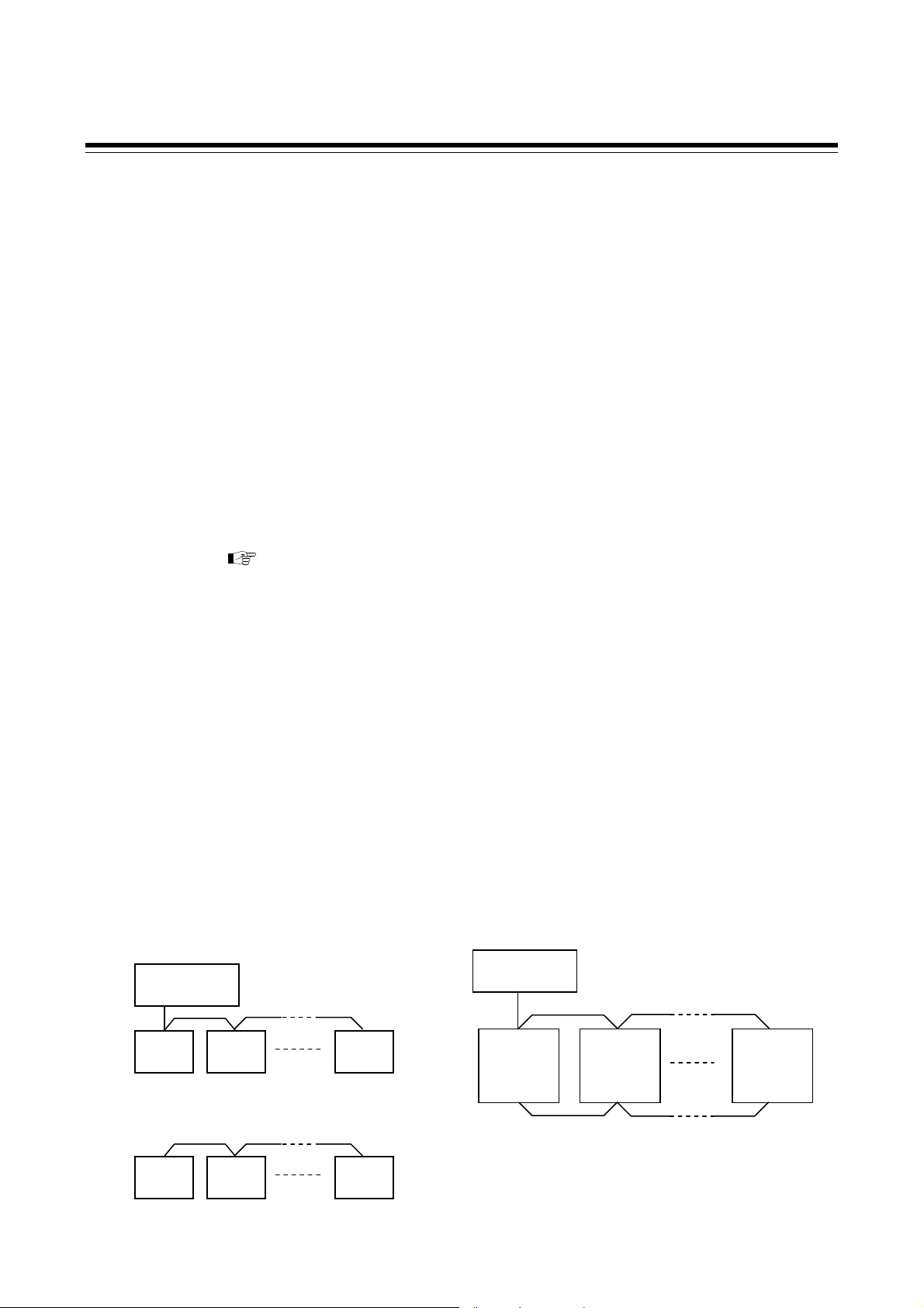
[Connection example]
When one-point communication is used When two-point communication is used
Host communication
Host
computer
FB100
COM1
FB100
COM1
FB100
COM1
Intercontroller communication
or
FB100
COM1
FB100
COM1
FB100
COM1
RS-485 only
Host
computer
COM1
FB100
COM2
Host communication
COM1
FB100
COM2
Intercontroller communication
(Cascade control, etc.)
COM1
FB100
COM2
1-14
IMR01W16-E7
Page 27
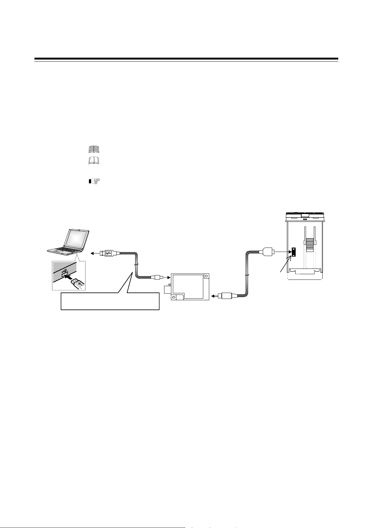
Loader communication
It is possible to manage data on the personal computer side by converting all of the
data in the FB100 into one file.
1
When starting the Loader communication, first your PC (Windows 2000/XP/
Vista/7) being used is necessary to be installed with the communication tool
http://www.rkcinst.com/.
1
Use our communication converter COM-K (sold separately) to connect FB100 and your PC.
2
The communication tool (WinUCI, PROTEM2) can be downloaded from the RKC official website:
The Loader port is only for parameter setup.
The Loader communication corresponds to the RKC communication protocol
“Based on ANSI X3.28-1976 subcategories 2.5 and A4.”
For the COM-K, refer to the COM-K Instruction Manual (IMR01Z01-E).
[Connection example]
1.5 Input/Output Functions
2
.
USB cable 1 m
(COM-K accessory)
Connected to USB
port of a personal
computer
Do not unplug the USB cable while the
power to the instrument is ON.
Communication m onitor tool WinUCI-A
Software operation environment: Windows 2000 or higher
Communication setup tool WinUCI -B for FB series
Software operation environment: Windows 2000 or higher
Communication tool PROTEM2
Software operation environment: Windows XP (Service Pack 2) or higher
PROTEM2 needs Microsoft .NET Framework 4.0 or later
Communication port of host computer
USB port: Based on USB Ver. 2.0
Communication settings on t he computer
(Values other than the communi c ation port are fixed.)
Communication speed: 38400 bps
Start bit: 1
Data bit: 8
Parity bit: Without
Stop bit: 1
Connected to
USB connecter
USB
communication
converter
COM-K
Connected to loader
communication
connector of the
FB100
Loader
communication cable
1.5 m (W-BV-01)
[COM-K optional]
Connected to loader
communication
connecter
Loader
communication
connector
The device address for
Loader communication is
fixed at “0.”
The setting of the device
address is disregarded.
FB100 bottom view
IMR01W16-E7
1-15
Page 28

MEMO
1-16 IMR01W16-E7
Page 29

HANDLING
PROCEDURE TO
OPERATION
IMR01W16-E7 2-1
Page 30

2. HANDLING PROCEDURE TO OPERATION
r
2. HANDLING PROCEDURE TO OPERATION
This chapter describes procedures to set operating conditions of a customer and parameter of various
setting modes.
Setting procedure to operation
Conduct necessary setting before operation according to the procedure described below.
Mounting and Wiring
When installing the instrument,
refer to 3. MOUNTING (P. 3-1) and
4. WIRING (P. 4-1).
When group operation by using Intercontrolle
communication is performed, refer to 6.14.1 Wiring
method of the Intercontroller communication
(P. 6-61).
Power ON
Change from RUN to STOP
The parameters in Engineering mode which should be set according to the application
are settable only when the controller is in STOP mode.
Setting of operating condition
(Engineering mode)
The parameters for controller’s basic functions in Engineering mode should be changed
according to the application before setting the parameters related to operation.
Be sure to check the parameters for the following settings and change them according to the
application if necessary. Other parameters should be also changed according to the application.
Power frequency [Factory set value 50Hz] (P. 7-78) Remote setting input type (P. 7-79) 2
Input type (P. 7-71)
Input scale high/low (P. 7-74)
Control action (P. 7-125)
Output assignment (P. 7-82)
1
This setting is not necessary when the quick start code "1" is specified.
2
This setting is not necessary when the quick start code "2" is specified.
3
This setting is not necessary when the quick start code "N" is specified.
When group operation by using Intercontroller communication is performed, set the
following setting items.
Digital input (DI) assignment (P. 7-80) 1 Automatic temperature rise group (P. 7-159) 4
External input type (P. 7-121)
Master channel selection (P. 7-122)
1
Group RUN/STOP function (P.6-64)
2
Cascade control function (P. 6-81)
Refer to 7.5. Engineering Mode (P. 7-52).
A
Entry to data sheet
Use the sheet of Appendix E,
and make record of setting
data of a customer.
Change from RUN mode to STOP mode with the RUN/STOP transfer. (P. 6-11)
Factory set value: RUN (control start)
1, 2
Event type (P. 7-88, 7-97, 7-101, 7-105)
1, 2
Transmission output type (P. 7-86) 3
1, 2
Communication protocol (P. 7-162) 3
1, 2
2, 3
RUN/STOP group (P. 7-160)
2, 3
3
Ratio setting function (P. 6-89)
4
Automatic temperature rise func tion (P. 6-72)
1, 4
2, 3
2-2 IMR01W16-E7
Page 31

2. HANDLING PROCEDURE TO OPERATION
n
e
a
A
Control action type?
Position proportioning PID control
PID control or
Heat/Cool PID control
Adjustment of the valve position
For details, refer to
page 6-43.
Setup data setting
(Setup setting mode)
Set parameters in Setup setting mode:
Heater break alarm relationships (optional),
Input correction relationships,
Communication (optional), etc.
Refer to 7.4 Setup Setting Mode
(P. 7-37).
To perform group operation by using Intercontroller communication
Set the Device address, RS
bias*, RS digital filter* and RS
ratio*.
* These parameter settings are also used for
Cascade control function (P. 6-81) and
Ratio setting function (P. 6-89).
Adjust the above parameter setting values
when finely adjustment is required.
For details, refer to
page 6-61.
Parameter data setting
To perform Ramp/Soak operation
Set parameters in Parameter setting mode:
Event function relationships,
PID and control response, etc.
Up to 8 individual sets of parameters i
Parameter setting mode and SVs can b
stored and used in Multi-memory are
function.
Refer to 7.3 Parameter Setting Mode (P. 7-22).
Set the Setting change rate
limiter, Area soak time and
Link area number.
For details, refer to
page 6-52.
Set value (SV) setting
Set the control set value (SV) which is target value of the control (refer to page 6-5).
The Set value (SV) can be stored up to 8 areas in Multi-memory area function as well as
parameters in Parameter setting mode.
B
IMR01W16-E7
2-3
Page 32

2. HANDLING PROCEDURE TO OPERATION
g
B
Is Multi-memory Area *
function used?
Yes
* Factory set value: Memory area 1
No
Control Memory Area selection
Select the Memory area in SV setting & monitor mode.
For details of memory area selection, refer to 6.9 Control Area
Transfer (P. 6-33).
Tuning type?
Startup tuning (ST)
Autotuning (AT)
[Change from STOP mode to RUN mode with the RUN/STOP transfer (P. 6-11). Operation starts as soon as
the RUN/STOP mode is changed to RUN mode.]
Change from STOP to RUN
Change from PID to AT
(Operation mode: PID/AT transfer)
Change from “oFF (PID)” to “on (AT)”
with the PID/AT transfer (P. 7-15).
AT starts as soon as the PID/AT transfer
ed to “on.”
is chan
ST type setting
(Operation mode: STU)
(P. 6-18)
AT end
When the autotuning is finished,
the controller will automatically
returns to PID control.
ST end
When the startup tuning is finished,
the controller will automatically
returns to PID control.
Operation *
* Adjust the PID constants manually when the optimum PID constants cannot be computed by Autotuning for characteristic
variations of the controlled system (refer to page 6-9).
2-4
IMR01W16-E7
Page 33

MOUNTING
3.1 Mounting Cautions. ........................................................................... 3-2
3.2 Dimensions ....................................................................................... 3-3
3.3 Procedures of Mounting and Removing ............................................ 3-4
IMR01W16-E7 3-1
Page 34

3. MOUNTING
3.1 Mounting Cautions
This chapter describes installation environment, mounting cautions, dimensions and mounting
procedures.
To prevent electric shock or instrument failure, always turn off the power before
mounting or removing the instrument.
(1) This instrument is intended to be used under the following environmental conditions. (IEC61010-1)
[OVERVOLTAGE CATEGORY II, POLLUTION DEGREE 2]
(2) Use this instrument within the following environment conditions:
Allowable ambient temperature: 10 to 50 C
Allowable ambient humidity: 5 to 95 %RH
(Absolute humidity: MAX. W. C 29.3 g/m
Installation environment conditions: Indoor use
Altitude up to 2000 m
WARNING
!
3
dry air at 101.3 kPa)
(3) Avoid the following conditions when selecting the mounting location:
Rapid changes in ambient temperature which may cause condensation.
Corrosive or inflammable gases.
Direct vibration or shock to the mainframe.
Water, oil, chemicals, vapor or steam splashes.
Excessive dust, salt or iron particles.
Excessive induction noise, static electricity, magnetic fields or noise.
Direct air flow from an air conditioner.
Exposure to direct sunlight.
Excessive heat accumulation.
(4) Mount this instrument in the panel considering the following conditions:
Provide adequate ventilation space so that heat does not build up.
Do not mount this instrument directly above equipment that generates large amount of heat (heaters,
transformers, semi-conductor functional devices, large-wattage resistors.)
If the ambient temperature rises above 50 C, cool this instrument with a forced air fan, cooler, etc.
Cooled air should not blow directly on this instrument.
In order to improve safety and the immunity to withstand noise, mount this instrument as far away as
possible from high voltage equipment, power lines, and rotating machinery.
High voltage equipment: Do not mount within the same panel.
Power lines: Separate at least 200 mm.
Rotating machinery: Separate as far as possible.
Mount this instrument in the horizontal direction for panel. If you did installation except a horizontal
direction, this causes malfunction.
(5) If this instrument is permanently connected to equipment, it is important to include a switch or
circuit-breaker into the installation. This should be in close proximity to the equipment and within
easy reach of the operator. It should be marked as the disconnecting device for the equipment.
3-2 IMR01W16-E7
Page 35

3. MOUNTING
3.2 Dimensions
(Unit: mm )
49.2
44.8
48
*2
48
48.2
59.3
10.7
*1
1
74
90.1
Panel thickness: 1 to 10 mm
(When mounting multiple FB100s close together, the panel strength should be checked to ensure proper support.)
0
0.6
*4、*5
Individual mounting *3
0.6
25
45
0
Close mounting
L
0.6
0
45
0.6
0
45
30
L = 48 n 3
n: Number of controllers (2 to 6)
*1 Case rubber packing
*2 Terminal cover KCA100-517 (optional) [sold separately]
*3 When cutting out each mounting hole through a panel for individual mounting, observe that there is no bur or distortion along
the panel cutout surface, or there is no bend on the panel surface. If so, the water resistant characteristics may worsen.
*4 Remove the case rubber packing. When the FB series is mounted closely protection will be compromised and they will not
meet IP66 (NEMA 4X) standards.
*5 When controllers are closely mounted, ambient temperature must not exceed 50 C.
IMR01W16-E7 3-3
Page 36

3. MOUNTING
図
3.3
Procedures of Mounting and Removing
Mounting procedures
1. Prepare the panel cutout as specified in 3.2 Dimensions.
(Panel thickness: 1 to 10 mm)
2. Insert the instrument through the panel cutout.
3. Insert the mounting bracket into the mounting groove
of the instrument. (Fig. 3.1)
4. Push the moun ting bracket forward until the bracket is
firmly secured to the panel. (Fig. 3.2)
5. Only turn one full revolution after the screw touches the
panel. (Fig. 3.3)
6. The other mounting bracket should be installed the
same way described in 3. to 5.
The front of the instrument conforms to IP66
(NEMA4X) when mounted on the panel.
For effective Waterproof/Dustproof, the gasket
must be securely placed between instrument and
panel without any gap. If gasket is damaged, please
contact RKC sales office or the agent.
Fig.3.1
図1
Fig. 3.2
図2
Fig. 3.3
図3
For replacing of rubber packing, refer to
APPENDIX B. Replacing the Waterproof/
Dustproof Rubber Packing (P. A-4).
Removing procedures
1. Turn the power OFF.
2. Remove the wiring.
3. Loosen the screw of the mounting bracket. (Fig. 3.4)
4. Lift the latch of the mounting bracket (), then pull
the mounting bracket () to remove it from the case.
(Fig. 3.4)
5. The other mounting bracket should be removed in the
same way as described in 3. and 4.
6. Pull out the instrument from the mounting cutout
while holding the front panel frame of this instrument.
(Fig. 3.5)
Use long-nose pliers to
remove mounting brackets
from the instrument that is
installed in a narrow place
or installed tightly in a
vertical position.
Fig. 3.4
図4
Loosen the screw
ネジを緩めた状態
Fig. 3.5
Pull out
Front panel frame
①
②
Panel
3-4 IMR01W16-E7
Page 37

WIRING
4.1 Wiring Cautions ................................................................................ 4-2
4.2 Terminal Layout ................................................................................ 4-4
4.3 Wiring of Each Terminal ................................................................... 4-6
4.3.1 Power ................................................................................................... 4-6
4.3.2 Output 1 (OUT1)/Output 2 (OUT2) ....................................................... 4-7
4.3.3 Digital output 1, 2 (DO1, DO2) ............................................................. 4-9
4.3.4 Measurement input (Thermocouple/RTD/Voltage/Current) ................. 4-9
4.3.5 Optional .............................................................................................. 4-10
IMR01W16-E7 4-1
Page 38

4. WIRING
4.1 Wiring Cautions
This chapter describes wiring cautions, wiring layout and wiring of terminals.
To prevent electric shock or instrument failure, do not turn on the power until all
wiring is completed. Make sure that the wiring is correct before applying power
to the instrument.
WARNING
!
For thermocouple input, use the appropriate compensation wire.
For RTD input, use low resistance lead wire with no difference in resistance between the three lead
wires.
To avoid noise induction, keep input signal wire away from instrument power line, load lines and
power lines of other electric equipment.
If there is electrical noise in the vicinity of the instrument that could affect operation, use a noise
filter.
Shorten the distance between the twisted power supply wire pitches to achieve the most effective
noise reduction.
Always install the noise filter on a grounded panel. Minimize the wiring distance between the
noise filter output and the instrument power supply terminals to achieve the most effective noise
reduction.
Do not connect fuses or switches to the noise filter output wiring as this will reduce the
effectiveness of the noise filter.
Allow approximately 5 seconds for contact output when the instrument is turned on. Use a delay
relay when the output line is used for an external interlock circuit.
Power supply wiring must be twisted and have a low voltage drop.
For an instrument with 24 V power supply, supply power from a SELV circuit.
A suitable power supply should be considered in end-use equipment. The power supply must be in
compliance with a limited-energy circuits (maximum available current of 8 A).
This instrument is not furnished with a power supply switch or fuse. If a fuse or power supply switch
is required, install close to the instrument.
Recommended fuse rating: Rated voltage 250 V, Rated current 1 A
Fuse type: Time-lag fuse
Use the solderless terminal appropriate to the screw size.
Screw size: M3 7 (With 5.8 5.8 square washer)
Recommended tightening torque:
Fig. 4.1
5.5 MAX
3.2 MIN
0.4 N・m (4 kgf・cm)
2
Applicable wire: Solid/twisted wire of 0.25 to 1.65 mm
Specified dimension: Refer to Fig. 4.1
Specified solderless terminals:
Manufactured by J.S.T MFG CO., LTD.
5.6 mm
9.0 mm
Circular terminal with isolation
V1.25-MS3
(M3 screw, width 5.5 mm, hole diameter 3.2 mm)
Make sure that the any wiring such as solderless terminal is not in contact with the adjoining terminals.
5.0
4-2 IMR01W16-E7
Page 39

4.1 Wiring Cautions
f
When wiring, wire from the left direction toward the backside terminals as shown in Fig. 4.2.
For FB100, the wiring surfaces of the central and right side lines of terminals are inclined to make it
easier to wire from the left side.
When using the terminal cover (Figs. 4.2), it is not possible to wire from the right side.
When wiring from the left and right with a clo se moun ting, there a re cases wh ere adjacent instr uments
cannot be wired.
Fig. 4.2 Wiring direction
Wire from the left side
When equipped with a terminal cover
Wire from the
le
t side
It is not possible
to wire from the
right side.
Up to two solderless terminal lugs can be connected to one terminal screw.
However, reinforced insulation cannot be used
.
Fig. 4.3 Image of how to bend each solderless terminal lug
Panel
Top view
If solderless terminal lugs other than the recommended dimensions are used, terminal screws
may not tighten. In that case, bend each solderless terminal lug before wiring.
If the terminal screw is forcibly tightened, it may be damaged.
If two solderless terminal lugs are connected to one terminal screw, a terminal cover cannot
be used.
Caution for the terminal cover usage:
To prevent electrical shock or instrument failure, always turn off the power before mounting or
removing the terminal cover.
When mounting and removing the terminal cover, apply pressure very carefully to avoid damage
to the terminal cover.
IMR01W16-E7
4-3
Page 40

4. WIRING
4.2 Terminal Layout
The terminal layout is as follows.
Power supply voltage
[Refer to P. 4-6]
100 to 240 V AC, 24 V AC, 24 V DC
Output 2 (OUT2)
[Refer to P. 4-7]
Relay contact/Voltage pulse/
Voltage/Current/Triac/
Open collector
Output 1 (OUT1)
[Refer to P. 4-7]
Relay contact/Voltage pulse/
Voltage/Current/Triac/
Open collector
Digital output 2 (DO2),
Digital output 1 (DO1)
[Refer to P. 4-9]
Relay contact
Measured input
[Refer to P. 4-9]
Thermocouple/RTD/Voltage/Current
Optional
Optional function: A Digital input (DI1 to DI5)
[Refer to P. 4-10]
Optional function: B Digital input (DI1, DI2)
Remote setting (RS) input
[Refer to P. 4-11]
[Voltage/Current]
Optional function: C Digital input (DI1, DI2)
Feedback resistance (FBR) input
[Refer to P. 4-12]
Optional function: D Digital input (DI1, DI2)
Current transformer input (CT1, CT2)
[Refer to P. 4-13]
Optional function: E Digital input (DI1 to DI3)
Communication 1 (RKC communication, Modbus, Intercontroller communication)
Optional function: F Digital input (DI1)
Current transformer input (CT1)
Communication 1 (RKC communication, Modbus, Intercontroller communication)
Optional function: G Communication 1 (RKC com m unication, Modbus) [RS-485]
Communication 2 (Intercontroller communication)
Optional function: H Communication 1 (RKC communication, Modbus, Intercontroller communication) [RS-485]
Current transformer input (CT1, CT2)
[Refer to P. 4-17]
Optional function: J Communication 1 (RKC communication, Modbus, Intercontroller communication)
Digital input (DI1)
Remote setting (RS) input
[Refer to P. 4-18]
Optional function: 3, 4, 5, 6, 7, 8
Digital input (DI1)
Remote setting (RS) input
Transmission output (AO)
[Refer to P. 4-14]
[Refer to P. 4-15]
[RS-485]
[Refer to P. 4-16]
[Voltage/Current]
[Voltage/Current]
[Voltage/Current]
[Refer to P. 4-20]
[RS-485]
[RS-485]
[RS-485]
4-4 IMR01W16-E7
Page 41

Isolations of input and output
For isolated device input/output blocks, refer to the following:
Commu-
nication
(RS-485)
Digital
input
DI1
DI2
DI3
DI4
DI5
Isolated Isolated Isolated Isolated
Output 1
1
(OUT1)
Output 2 1
(OUT2)
Transmission
output
1
(AO)
Power supply
Non-isolated
Loader
commu-
nication
MCU
Non-isolated
Measured input
Current
transformer input
(CT1, CT2)
Remote setting
(RS) input
Feedback
resistance input
(One of the above)
4.2 Terminal Layout
Isolated IsolatedIsolated
Digital
output
DO1
DO2
2
1
Outputs are isolated if Output 1 (OUT1) or Output 2 (OUT2) is Relay contact output or Triac trigger output.
If both outputs are Relay contact output or Triac trigger output, outputs are not isolated.
2
During output of Digital output (Relay contact output only), all are in an “Isolated” relationship.
IMR01W16-E7
4-5
Page 42

4. WIRING
A
A
4.3 Wiring of Each Terminal
Prior to conducting wiring, always check the polarity of each terminal.
4.3.1 Power supply
Connect the power to terminal numbers 1 and 2.
L
C
100-240 V
100-240 V AC power
supply type
1
2
N
24 V AC power supply type 24 V DC power supply type
C
24 V
L
1
2
N
DC
24 V
1
2
Power supply types must be specified when ordering. Power supply voltage for the controller must
be within the range shown below to accurse control accuracy.
Specification
code
4
3
3
90 to 264 V AC (Power supply voltage range),
[Rating 100 to 240 V AC]
Power supply frequency: 50/60 Hz
21.6 to 26.4 V AC (Power supply voltage range),
[Rating 24 V AC]
Power supply frequency: 50/60 Hz
21.6 to 26.4 V DC (Power supply voltage range),
[Rating 24 V DC]
Power supply type Power consumption
5.4 VA max. (at 100 V AC),
8.1 VA max. (at 240 V AC)
5.3 VA max. (at 24 V AC)
142 mA max. (at 24 V DC)
If there is electrical noise in the vicinity of the instrument that could affect operation, use a noise
filter.
Power supply wiring must be twisted and have a low voltage drop.
This instrument is not furnished with a power supply switch or fuse. Therefore, if a fuse or power
supply switch is required, install close to the instrument.
Recommended fuse rating: Rated voltage 250 V, Rated current 1 A
Fuse type: Time-lag fuse
For an instrument with 24 V power supply, supply power from a SELV circuit.
A suitable power supply should be considered in end-use equipment. The power supply must be in
compliance with a limited-energy circuits (maximum available current of 8 A).
4-6 IMR01W16-E7
Page 43

4.3 Wiring of Each Terminal
4.3.2 Output 1 (OUT1)/Output 2 (OUT2)
Terminal 5 and 6 are for Output 1 (OUT1); Terminal 3 and 4 are for Output 2 (OUT2).
Connect an appropriate load according to the output type. (Specify when ordering)
Relay contact
output
Voltage pulse
output
Voltage output/
Current output
PID control
(Direct/Reverse
action)
Heat/Cool PID control
(or Position proportioning PID control)
Wiring example
NO
OUT1
5
6
OUT1
NO
Heat-side (Open-side)
5
6
OUT2
NO
Cool-side (Close-side)
3
4
NO
OUT1
5
6
OUT1
5
6
OUT1
Heat-side (Open-side)
5
6
OUT2
Cool-side (Close-side)
3
4
OUT1
0/12 V DC
5
6
OUT1
5
6
OUT1
Heat-side (Open-side)
5
6
OUT2
Cool-side (Close-side)
3
4
OUT1
0 to 20 mA DC
5
6
~
Load
SSR Load
~
Actuator
~
Load
Triac output
Open collector
output
Triac
OUT1
5
6
OUT1
Triac
5
6
OUT1
Triac
Heat-side (Open-side)
5
6
OUT2
Triac
Cool-side (Close-side)
3
4
OUT1
5
6
OUT1
Heat-side (Open-side)
5
6
OUT2
Cool-side (Close-side)
3
4
OUT1
5
6
~
Load
Load
OUT1 is not isolated from OUT2.
When OUT1 and OUT2 can be used for Relay contact output (250 V AC 3 A, 30 V DC 1 A) or
Triac output, there is isolation between each output (OUT1, OUT2, AO).
OUT1 and OUT2 can be used for control output, Heater break alarm output, Event output or FAIL
(De-energized fixed: Contact opens under FAIL). Refer to page 4-8.
Continued on the next page.
IMR01W16-E7
4-7
Page 44

4.3 Wiring of Each Terminal
Continued from the previous page.
Number of outputs and output types must be specified when ordering. The specifications of each
output are as follows.
Specification
code
M
V
4
5
6
7
8
T
D
Output type Specifications
Relay contact utput 250 V AC, 3A (Resistive load)/30 V DC, 1 A (Resistive load) 1a contact
Voltage pulse utput 0/12 V DC (Allowable load resistance: 600 or more)
0 to 5 V DC (Allowable load resistance: 1 k or more)
Voltage output
0 to 10 V DC (Allowable load resistance: 1 k or more)
1 to 5 V DC (Allowable load resistance: 1 k or more)
Current output
Triac output
0 to 20 mA DC (Allowable load resistance: 600 or less)
4 to 20 mA DC (Allowable load resistance: 600 or less)
AC output (Allowable load current: 0.5 A [Ambient temperature 40 C or less]),
Load voltage: 75 to 250 V AC, Minimum load current: 30 mA,
ON voltage: 1.6 V or less (at maximum load current)
Open collector
output
Sink type (Allowable load current: 100 mA), Load voltage: 30 V DC or less,
Minimum load current: 0.5 mA, ON voltage: 2 V or less (at maximum loa d c u rrent ),
Leakage current at OFF: 0.1 mA or less
Output assignments are either specified by Quick start code 2 when the order is placed, or set in
Engineering mode. Assignments are shown below.
Output Assignment Code Table
Code Output 1 (OUT1) Output 2 (OUT2) Digital output 1 (DO1) Digital output 2 (DO2)
01 Control output 1 Control output 2 Event output 1 (EV1) Event output 2 (EV2)
02 Control output 1 Control output 2 Event output 1 (EV1) Event output 4 (EV4)
03 Control output 1 Control output 2 Event output 1 (EV1) Heater break alarm (HBA) output
04 Control output 1 Control output 2 Event output 1 (EV1) FAIL output (De-energized)
05 Control output 1 Control output 2 Event output 4 (EV4) Heater break alarm (HBA) output
06 Control output 1 Control output 2 Event output 4 (EV4) FAIL output (De-energized)
07 Control output 1 Control output 2 Heater break alarm (HBA) output FAIL output (De-energized)
08 Control output 1 Heater break alarm (HBA) output Event output 1 (EV1) Event output 2 (EV2)
09 Control output 1 Heater break alarm (HBA) output Event output 1 (EV1) Event output 4 (EV4)
10 Control output 1 Heater break alarm (HBA) output Event output 1 (EV1) FAIL output (De-energized)
11 Control output 1 Heater break alarm (HBA) output Event output 4 (EV4) FAIL output (De-energized)
12 Control output 1 FAIL output (De-energized) Event output 1 (EV1) Event output 2 (EV2)
13 Control output 1 FAIL output (De-energized) Event output 1 (EV1) Event output 4 (EV4)
14 Control output 1 Event output 1 (EV1) Event output 2 (EV2) Event output 3 (EV3)
15 Control output 1 Event output 4 (EV4) Event output 1 (EV1) Event output 2 (EV2)
Energized/De-energized is configurable except for the FAIL output. (Factory shipment: Energized)
When Current transformer (CT) input is two-point input, Heater break alarm (HBA) output is OR output.
Invalid for a non-existing output/event function.
When used as Heat/Cool PID control, select any code of 1 to 7.
For Position proportioning PID control, output 1 (OUT1) is open-side output and output 2 (OUT2) is close-side output, regardless of the above
selection.
4-8
IMR01W16-E7
Page 45

12
4.3.3 Digital output 1, 2 (DO1, DO2)
Terminals 7 through 9 for Digital output (DO1, DO2).
DO2
DO1
Output type is only Relay contact output.
COM
NO
NO
7
8
9
Wiring example
COM
NO
DO2
NO
4.3 Wiring of Each Terminal
~
7
8
9DO1
Load
Load
Relay contact output
250 V AC, 1A (Resistive load)/30 V DC, 1 A (Resistive load) 1a contact
Electrical life: 300,000 times or more (Rated load)
DO1 and DO2 can be used for output of the Event function, Heater break alarm output, or FAIL
(De-energized fixed: Contact opens under FAIL). Refer to page 4-8.
4.3.4 Measured input (Thermocouple/RTD/Voltage/Current)
For the Measured input type, terminals 10 through 12 are allocated to the Measured input.
Thermocouple input
11
TC
12
The input types (input group) are as follows.
Input group Input type
Thermocouple K, J, E, T, S, R, B, N, PLII, W5Re/W26Re, U, L
Voltage (low) input
group
Voltage (high) input group
RTD Pt100, JPt100
Voltage (low)
Current 0 to 20 mA DC, 4 to 20 mA DC
RTD input
A
10
RTD
B
11
B
Voltage input
IN
11
12
0 to 1 V DC, 0 to 100 mV DC, 0 to 10 mV DC, 100 to 100 mV DC,
10 to 10 mV DC
1 to 1 V DC, 0 to 5 V DC, 1 to 5 V DC, 0 to 10 V DC
Current input
Current input
IN
IN
11
11
12
12
For Thermocouple input, use the appropriate compensation wire.
For RTD input, use low resistance lead wires with no difference in resistance between the three lead
wires.
To avoid noise induction, keep input signal wire away from instrument power line, load lines and
power lines of other electric equipment.
IMR01W16-E7
4-9
Page 46

4.3 Wiring of Each Terminal
4.3.5 Optional
Terminals 13 through 18 for optional function.
Optional function: A [Digital input (5 points)]
Digital input (DI1 to DI5)
Terminals 13 through 18 for DI1 to DI5.
Dry contact input
COM ()
DI1
DI2
DI3
DI4
DI5
13
14
15
16
17
18
Digital input from external devices or equipment should be dry contact input. If it is not dry contact
input, the input should have meet the specifications below.
Contact specifications: At OFF (contact open) 500 k or more
At ON (contact closed) 10 or less
The following functions can be assigned to Digital inputs.
Memory area transfer (Number of area: 1 to 8) Area set,
Memory area transfer [without area set] (Number of area: 1 to 8),
RUN/STOP transfer, Re mote/Local transf er, Auto/Manual transfer, Interlock release
To assign functions to Digital inputs, refer to 7.5 Engineering Mode (P. 7-80).
4-10
IMR01W16-E7
Page 47

4.3 Wiring of Each Terminal
Optional function: B [Digital input (2 points), Remote setting input (1 point)]
Digital input (DI1, DI2)
Terminals 13 through 15 are used for DI1 and DI2.
Dry contact input
COM ()
DI1
DI2
13
14
15
Digital input from external devices or equipment should be dry contact input. If it is not dry contact
input, the input should have meet the specifications below.
Contact specifications: At OFF (contact open) 500 k or more
At ON (contact closed) 10 or less
The following functions can be assigned to Digital inputs.
RUN/STOP transfer, Re mote/Local transf er, Auto/Manual transfer, Interlock release
To assign functions to Digital inputs, refer to 7.5 Engineering Mode (P. 7-80).
Remote setting (RS) input
Remote setting (RS) input has provided as standard specifications.
Terminal 17 and 18 are used for Remote setting (RS) input. Connect an input according to the Remote
setting (RS) input type*.
* The following two methods of the RS input selection are available:
Specify when ordering (Initial setting code)
Setting by Remote setting (RS) input type of Engineering mode (Refer to page 7-79)
IN
17
18
<Initial setting code (Quick start code 2)> Any one of the following input types can be selected.
Specification
code
1
2
3
4
Input type
Voltage input (0 to 10 mV DC)
Voltage input (0 to 100 mV DC)
Voltage input (0 to 1 V DC)
Voltage input (0 to 5 V DC)
Specification
code
5
6
7
8
Input type
Voltage input (0 to 10 V DC)
Voltage input (1 to 5 V DC)
Voltage input (0 to 20 mA DC)
Voltage input (4 to 20 mA DC)
Remote setting (RS) input is not isolated from the Measured input.
In the case of optional function B, terminal 16 is not used, and is connected internally to SG
(signal ground).
IMR01W16-E7
4-11
Page 48

4.3 Wiring of Each Terminal
A
Optional function: C [Digital input (2 points), Feedback resistance input
(1 point)]
Digital input (DI1, DI2)
Terminals 13 through 15 are used for DI1 and DI2.
Dry contact input
COM ()
DI1
DI2
13
14
15
Digital input from external devices or equipment should be dry contact input. If it is not dry contact
input, the input should have meet the specifications below.
Contact specifications: At OFF (contact open) 500 k or more
At ON (contact closed) 10 or less
The following functions can be assigned to Digital inputs.
RUN/STOP transfer, Auto/Manual transfer, Interlock release
To assign functions to Digital inputs, refer to 7.5 Engineering Mode (P. 7-80).
Feedback resistance (FBR) input
For Feedback resistance (FBR) input, connect a potentiometer to terminals 16 to 18.
FBR input
O
16
17
W
18
C
llowance resistance:
Standard 135
Feedback resistance (FBR) input is not isolated from the Measured input.
4-12
IMR01W16-E7
Page 49

4.3 Wiring of Each Terminal
Optional function: D [Digital input (2 points), Current transformer input
(2 points)]
Digital input (DI1, DI2)
Terminals 13 through 15 are used for DI1 and DI2.
Dry contact input
COM ()
DI1
DI2
13
14
15
Digital input from external devices or equipment should be dry contact input. If it is not dry contact
input, the input should have meet the specifications below.
Contact specifications: At OFF (contact open) 500 k or more
At ON (contact closed) 10 or less
The following functions can be assigned to Digital inputs.
RUN/STOP transfer, Auto/Manual transfer, Interlock release
To assign functions to Digital inputs, refer to 7.5 Engineering Mode (P. 7-80).
Current transformer input (CT1, CT2)
For Current transformer input, connect Current transformers (CT) to terminals 16 to 18.
CT input
COM
CT1
CT2
16
17
18
Current transformer (CT) input is not isolated from the Measured input.
IMR01W16-E7
4-13
Page 50

4.3 Wiring of Each Terminal
Optional function: E [Communication (1 point), Digital input (3 points)]
Communication 1
Terminals 13 through 15 are used for Communication 1.
SG
T/R (A)
T/R (B)
13
14
15
For optional function: E, SG of Communication 1 and
COM () of Digital input share terminal 13.
RS-485
[Communication 1]
The communication interface is fixed at RS-485.
The Communication protocol of Communication 1 is either specified by Quick start code 2 when the
order is placed, or set in Engineering mode. Communication protocols that can be selected are as
follows:
RKC communication (ANSI X3.28-1976 Subcategories 2.5 and A4), Modbus-RTU, Intercontroller communication
For details of RKC communication and Modbus, refer to FB100 Communication Quick
Manual (IMR01W15-E) or FB100/FB400/FB900 Communication Instruction Manual
(IMR01W04-E).
For the Intercontroller communication, refer to 6.14 Group Operation by the Intercontroller
Communication (P. 6-61).
Digital input (DI1 to DI3)
DI1 to DI3 use terminal 13 and terminals 16 to 18.
Dry contact input
COM ()
DI1
DI2
DI3
13
14
15
16
17
18
For optional function: E, SG of Communication 1 and
COM () of Digital input share terminal 13.
Digital input from external devices or equipment should be dry contact input. If it is not dry contact
input, the input should have meet the specifications below.
Contact specifications: At OFF (contact open) 500 k or more
At ON (contact closed) 10 or less
The following functions can be assigned to Digital inputs.
Memory area transfer [without area set] (Number of area: 1 to 8),
RUN/STOP transfer, Re mote/Local transf er, Auto/Manual transfer, Interlock release
To assign functions to Digital inputs, refer to 7.5 Engineering Mode (P. 7-80).
4-14
IMR01W16-E7
Page 51

4.3 Wiring of Each Terminal
Optional function: F [Communication (1 point), Digital input (1 point),
Current transformer input (1 point)]
Communication 1
Terminals 13 through 15 are used for Communication 1.
RS-485
[Communication 1]
The communication interface is fixed at RS-485.
The Communication protocol of Communication 1 is either specified by Quick start code 2 when the
order is placed, or set in Engineering mode. Communication protocols that can be selected are as
follows:
RKC communication (ANSI X3.28-1976 Subcategories 2.5 and A4), Modbus-RTU, Intercontroller communication
For details of RKC communication and Modbus, refer to FB100 Communication Quick
Manual (IMR01W15-E) or FB100/FB400/FB900 Communication Instruction Manual
(IMR01W04-E).
SG
T/R (A)
T/R (B)
13
14
15
For optional function: F, SG of Communication 1 and
COM () of Digital input share terminal 13.
For the Intercontroller communication, refer to 6.14 Group Operation by the Intercontroller
Communication (P. 6-61).
Digital input (DI1)
Terminal 13 and 16 are used for DI1.
Dry contact input
COM ()
13
DI1
14
15
16
For optional function: F, SG of Communication 1 and
COM () of Digital input share terminal 13.
Digital input from external devices or equipment should be dry contact input. If it is not dry contact
input, the input should have meet the specifications below.
Contact specifications: At OFF (contact open) 500 k or more
At ON (contact closed) 10 or less
The following functions can be assigned to Digital inputs.
RUN/STOP transfer, Re mote/Local transf er, Auto/Manual transfer, Interlock release
To assign functions to Digital inputs, refer to 7.5 Engineering Mode (P. 7-80).
Current transformer input (CT1)
For Current transformer (CT) input, connect a Current transformer (CT) to terminals 17 and 18.
CT input
COM
CT1
17
18
Current transformer (CT) input is not isolated from the Measured input.
IMR01W16-E7
4-15
Page 52

4.3 Wiring of Each Terminal
Optional function: G [Communication (2 points)]
Communication 1/Communication 2
Terminals 13 through 15 are used for Communication 1; Terminals 16 through 18 are used for
Communication 2.
SG
T/R (A)
T/R (B)
SG
T/R (A)
T/R (B)
13
14
15
16
17
18
RS-485
[Communication 1]
RS-485
[Communication 2]
The communication interface is fixed at RS-485.
The Communication protocol of Communication 1 is either specified by Quick start code 2 when the
order is placed, or set in Engineering mode. Communication protocols that can be selected are as
follows:
RKC communication (ANSI X3.28-1976 Subcategories 2.5 and A4), Modbus-RTU
The Communication protocol of Communication 2 is fixed at Intercontroller communication.
For details of RKC communication and Modbus, refer to FB100 Communication Quick
Manual (IMR01W15-E) or FB100/FB400/FB900 Communication Instruction Manual
(IMR01W04-E).
For the Intercontroller communication, refer to 6.14 Group Operation by the Intercontroller
Communication (P. 6-61).
4-16
IMR01W16-E7
Page 53

4.3 Wiring of Each Terminal
Optional function: H [Communication (1 point), Current transformer input
(2 points)]
Communication 1
Terminals 13 through 15 are used for Communication 1.
SG
T/R (A)
T/R (B)
13
14
15
RS-485
[Communication 1]
The communication interface is fixed at RS-485.
The Communication protocol of Communication 1 is either specified by Quick start code 2 when the
order is placed, or set in Engineering mode. Communication protocols that can be selected are as
follows:
RKC communication (ANSI X3.28-1976 Subcategories 2.5 and A4), Modbus-RTU, Intercontroller communication
For details of RKC communication and Modbus, refer to FB100 Communication Quick
Manual (IMR01W15-E) or FB100/FB400/FB900 Communication Instruction Manual
(IMR01W04-E).
For the Intercontroller communication, refer to 6.14 Group Operation by the Intercontroller
Communication (P. 6-61).
Current transformer input (CT1, CT2)
For Current transformer (CT) input, connect Current transformers (CT) to terminals 16 to 18.
CT input
COM
CT1
CT2
16
17
18
Current transformer (CT) input is not isolated from the Measured input.
IMR01W16-E7
4-17
Page 54

4.3 Wiring of Each Terminal
Optional function: J [Communication (1 point), Digital input (1 point),
Remote setting input (1 point)]
Communication 1
Terminals 13 through 15 are used for Communication 1.
SG
T/R (A)
T/R (B)
13
14
15
RS-485
[Communication 1]
The communication interface is fixed at RS-485.
The Communication protocol of Communication 1 is either specified by Quick start code 2 when the
order is placed, or set in Engineering mode. Communication protocols that can be selected are as
follows:
RKC communication (ANSI X3.28-1976 Subcategories 2.5 and A4), Modbus-RTU, Intercontroller communication
For details of RKC communication and Modbus, refer to FB100 Communication Quick
Manual (IMR01W15-E) or FB100/FB400/FB900 Communication Instruction Manual
(IMR01W04-E).
For the Intercontroller communication, refer to 6.14 Group Operation by the Intercontroller
Communication (P. 6-61).
Digital input (DI1)
Terminal 13 and 16 are used for DI1.
Dry contact input
COM ()
DI1
13
14
15
16
For optional function: J, SG of Communication 1 and
COM () of Digital input share terminal 13.
Digital input from external devices or equipment should be dry contact input. If it is not dry contact
input, the input should have meet the specifications below.
Contact specifications: At OFF (contact open) 500 k or more
At ON (contact closed) 10 or less
The following functions can be assigned to Digital inputs.
RUN/STOP transfer, Re mote/Local transf er, Auto/Manual transfer, Interlock release
To assign functions to Digital inputs, refer to 7.5 Engineering Mode (P. 7-80).
4-18
IMR01W16-E7
Page 55

4.3 Wiring of Each Terminal
Remote setting (RS) input
Remote setting (RS) input has provided as standard specifications.
Terminal 17 and 18 are used for Remote setting (RS) input. Connect an input according to the Remote
setting (RS) input type*.
* The following two methods of the RS input selection are available:
Specify when ordering (Initial setting code)
Setting by Remote setting (RS) input type of Engineering mode (Refer to page 7-79)
IN
17
18
< Initial setting code (Quick start code 2)> Any one of the following input types can be selected.
Specification
code
1
2
3
4
Input type
Voltage input (0 to 10 mV DC)
Voltage input (0 to 100 mV DC)
Voltage input (0 to 1 V DC)
Voltage input (0 to 5 V DC)
Specification
code
5
6
7
8
Input type
Voltage input (0 to 10 V DC)
Voltage input (1 to 5 V DC)
Voltage input (0 to 20 mA DC)
Voltage input (4 to 20 mA DC)
Remote setting (RS) input is not isolated from the Measured input.
IMR01W16-E7
4-19
Page 56

4.3 Wiring of Each Terminal
A
Optional function: 3, 4, 5, 6, 7, 8 [Digital input (1 point), Transmission output
(1 point), Remote setting input (1 point)]
Digital input (DI1)
Terminal 13 and 14 are used for DI1.
Digital input from external devices or equipment should be dry contact input. If it is not dry contact
input, the input should have meet the specifications below.
Contact specifications: At OFF (contact open) 500 k or more
At ON (contact closed) 10 or less
The following functions can be assigned to Digital inputs.
RUN/STOP transfer, Re mote/Local transf er, Auto/Manual transfer, Interlock release
To assign functions to Digital inputs, refer to 7.5 Engineering Mode (P. 7-80).
Remote setting (RS) input
Remote setting (RS) input has provided as standard specifications.
Terminal 15 and 16 are used for Remote setting (RS) input. Connect an input according to the Remote
setting (RS) input type*.
* The following two methods of the RS input selection are available:
Specify when ordering (Initial setting code)
Setting by Remote setting (RS) input type of Engineering mode (Refer to page 7-79)
IN
15
16
Dry contact input
COM ()
13
DI1
14
< Initial setting code (Quick start code 2)> Any one of the following input types can be selected.
Specification
code
1
2
3
4
Input type
Voltage input (0 to 10 mV DC)
Voltage input (0 to 100 mV DC)
Voltage input (0 to 1 V DC)
Voltage input (0 to 5 V DC)
Specification
code
5
6
7
8
Input type
Voltage input (0 to 10 V DC)
Voltage input (1 to 5 V DC)
Voltage input (0 to 20 mA DC)
Voltage input (4 to 20 mA DC)
Remote setting (RS) input is not isolated from the Measured input.
Transmission output (AO)
Terminal 17 and 18 are used for Transmission output (AO).
AO
O
17
18
17
18
Recorder
Wiring example
4 to 20 mA DC
4-20
<Initial set code>
Specification
code
3
4
5
6
7
8
Output
type
Voltage
output
Current
output
Specifications
0 to 1 V DC (Load resistance: 1 k or more)
0 to 5 V DC (Load resistance: 1 k or more)
0 to 10 V DC (Load resistance: 1 k or more)
1 to 5 V DC (Load resistance: 1 k or more)
0 to 20 mA DC (Load resistance: 600 or less)
4 to 20 mA DC (Load resistance: 600 or less)
IMR01W16-E7
Page 57

OPERTION MENU
AND
BASIC OPERTION
5.1 Operation Menu ................................................................................ 5-2
5.2 Basic Operation ................................................................................ 5-4
5.2.1 Scrolling through parameters ............................................................... 5-4
5.2.2 Changing set value (SV) ...................................................................... 5-9
5.2.3 Operation of the direct key ................................................................. 5-10
5.2.4 Data lock function ............................................................................... 5-11
IMR01W16-E7 5-1
Page 58

5. OPERATION MENU AND BASIC OPERATION
5.1 Operation Menu
The controller has five different setting modes. All settable parameters belong to one of them.
The following chart shows how to access different setting mode.
For the details of key operation, refer to 5.2 Basic Operation (P. 5-4).
Power ON
Input type/Input range Display
Press the
shift key
while
pressing
the SET key.
SV setting & monitor mode
- Set or change Set value (SV).
- Monitor parameters such as PV, SV
and MV.
- Conduct operation in this mode.
(Refer to P. 7-2)
Press and hold
the SET key
for 2 seconds.
Press and hold
the shift key
for 2 seconds.
- Change Operation status/mode such
- Set Startup tuning (ST).
Operation mode
as PID/AT, Auto/Manual, and
Remote/Local.
(Refer to P. 7-14)
Parameter setting mode
- Change parameters related to
control such as PID values.
- Stores up to 8 individual sets of
parameters and SVs by
Multi-memory area function.
(Refer to P. 7-22)
Press and hold
the SET key
for 2 seconds.
Setup setting mode
Set setting items not being in the
memory area and lock levels.
(Refer to P. 7-37)
Press the shift key while
pressing the SET key for
2 seconds.
The parameters in Engineering
mode which should be set
according to the application are
settable only when the controller is
in STOP mode.
Engineering mode
Change basic control functions such
as Input/Output assignment.
Press the shift key
while pressing
the SET key.
(Refer to P. 7-52)
Display returns to the SV setting and monitor mode from the Operation mode or the
Parameter setting mode by pressing the shift key while pressing the SET key.
Display returns to the Measured value (PV)/Set value (SV) monitor screen if no key
operation is performed within 1 minute (except during the Feedback adjustment).
Parameters not being specified are not displayed except in the Engineering mode.
5-2 IMR01W16-E7
Page 59

5.1 Operation Menu
A
A
Input type and input range display
This instrument immediately confirms inputs type symbol and input range following power ON.
Example: When sensor type is K thermocouple
Power ON
PV
SV AREA
InP
@Cn KP
utomatically
(in 2 seconds)
Symbol
Input type symbol (Refer to table 1)
Unit for input and SV display:
Celsius: C
Fahrenheit: F
Voltage/Current: no character shown
Table 1: Input type symbol table
Symbol Input type
K
J
Thermocouple K
Thermocouple J
PV
1372
SV AREA
- @ 200P
PV
SV AREA
utomatically
(in 2 seconds)
28
01
Input scale high
Input scale low
SV setting & monitor mode
Measured value (PV)/
Set value (SV) monitor
T
S
R
E
B
N
P
W
U
L
PT
JP
V
I
Thermocouple T
Thermocouple S
Thermocouple R
Thermocouple E
Thermocouple B
Thermocouple N
Thermocouple PLII
Thermocouple W5Re/W26Re
Thermocouple U
Thermocouple L
RTD Pt100
RTD JPt100
Voltage (mV, V)
Current (mA)
IMR01W16-E7
5-3
Page 60

5. OPERATION MENU AND BASIC OPERATION
y
A
y
y
5.2 Basic Operation
Basic key operations common to each mode (set item change, set value change and registration) and
Data lock function are described in the following.
5.2.1 Scrolling through parameters
SV setting & monitor mode
Operation method for SV setting & monitor mode differs depending on the Direct key type.
Direct key types include Auto/Manual transfer, Monitor, Memory area transfer, Remote/Local transfer
and RUN/STOP transfer. The operation of Monitor differs from the other types.
The Direct key type can be selected in Engineering mode.
When the direct key type is Auto/Manual transfer:
The monitor screen, setting screens, and memory area transfer screen appear together.
Pressing the SET key enables the selection of only setting screens in SV setting & monitor mode.
To go back to the first parameter, keep pressing SET keys until it is displayed again.
(Factory set value: Auto/Manual transfer)
For details of SV setting & monitor mode, refer to 7.1 SV Setting & Monitor Mode (P. 7-2).
Press the Direct key to switch between Auto mode and Manual mode.
Measured value (PV)/
Set value (SV) monitor
PV
28
SV AREA
(P.7-5)
Auto/Manual transfer (A-M)
Manual
mode
lamp lights
Automaticall
PV
Manual mode display
PV
Auto/Manual transfer (A-M)
PV
0 1
MAN
A-M
SV AREA
MAN
SV AREA
A-M
SV AREA
Direct ke
MAN1
utomatically
28
105 01
Direct ke
AUTo1
Set value (SV)
PV
SET
key
Manipulated output
value (MV1)
displayed
SV
SV AREA
00001
(P.7-7) (P.7-7) (P.7-7) (P.7-7)
Current transformer 1
(CT1) input value monitor
PV
SET
key
CT1
SVAREA
SET
key
001
Event monitor 1
PV
EVM1
SVAREA
SET
key
-02001
(P.7-8) (P.7-8)
Manipulated output value (MV2)
monitor [cool-side]
PV
MV2
SVAREA
SET
key
-00501
(P.7-9) (P.7-10)
Manipulated output value
at MV transfer
PV
PSM`
SVAREA
SET
key
00001
(P.7-11)
Current transformer 1
(CT1) input value monitor
PV
Event monitor 2
PV
soak time monitor
PV
Interlock release
PV
CT2
SVAREA
001
EVM2
SVAREA
001
Memory area
APT
SVAREA
0001
ILr
SVAREA
oFF1
(P.7-13)
Remote setting (RS)
input value monitor
SET
key
PV
SVr
SV AREA
SET
key
-0 2001
Manipulated output value (MV1)
monitor [heat-side]
SET
key
PV
SV AREA
MV
SET
key
-00501
(P.7-9)
Memory area transfer
SET
key
PV
ArE
SV AREA
SET
key
00011
(P.7-11)
SET
key
5-4 IMR01W16-E7
Page 61
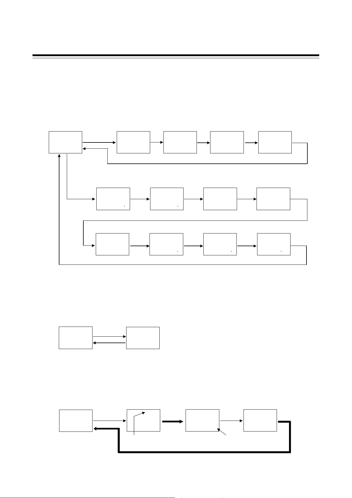
A
y
A
y
When the direct key type is Monitor:
The monitoring, setting and memory area transfer screen are mixedly displayed.
Pressing the SET key enables screen selection.
To go back to the first parameter, keep pressing SET keys until it is displayed again.
The monitor screen can be changed by pressing the Direct key.
Measured value (PV)/
Set value (SV) monitor
PV
28
SV AREA
0 1
(P.7-5)
Direct
SET
key
Current transformer 1
(CT1) input value monitor
PV
key
CT1
SVAREA
Set value (SV)
PV
SV
SV AREA
00001
(P.7-7)
Direct
key
001
(P.7-7) (P.7-7) (P.7-7)
Memory area transfer
PV
SET
key
ArE
SVAREA
00011
(P.7-11)
Current transformer 2
(CT2) input value monitor
PV
CT2
SVAREA
001
Manipulated output value
SET
key
Remote setting (RS)
Input value monitor
PV
Direct
key
at MV transfer
PV
PSM`
SVAREA
00001
(P.7-11)
SVr
SVAREA
-0 2001
SET
Direct
key
5.2 Basic Operation
Interlock release
PV
key
ILr
SV AREA
oFF1
(P.7-13)
Event monitor 1
PV
EVM1
SV AREA
-02001
(P.7-8)
SET
key
Direct
key
Event monitor 2
PV
EVM2
SVAREA
001
(P.7-8)
Manipulated output value (MV1)
monitor [heat-side]
PV
Direct
key
MV
SVAREA
-00501
(P.7-9)
Manipulated output value (MV2)
monitor [cool-side]
PV
Direct
key
MV2
SVAREA
-00501
(P.7-9)
Direct
key
Memory area
soak time monitor
PV
APT
SV AREA
0001
(P.7-10)
When the direct key type is Memory area transfer:
The screens when the SET key is pressed are the same as for Auto/Manual transfer (Refer to P. 5-4).
When the Direct key is pressed, the memory area transfer screen appears.
Press the SET key to return to the Measured value (PV)/Set value (SV) monitor screen.
Measured value (PV)/
Set value (SV) monitor
PV
28
SV AREA
0 1
(P.6-35)
Direct key
SET key
Memory area transfer
(ArE)
PV
ArE
SV AREA
00011
(P.6-35)
When the direct key type is Remote/Local transfer:
The screens when the SET key is pressed are the same as for Auto/Manual transfer (Refer to P. 5-4).
Press the Direct key to switch between Remote mode and Local mode.
Measured value (PV)/Set value (SV)
monitor (Local mode)
PV
28
SV AREA
Direct key
01
Remote/Local transfer
(r-L)
r-L
SV AREA
REM
PV
rEM1
(P. 6-30)(P. 6-30)
Remote
mode
lamp lights
utomaticall
Remote mode display
REM
PV
28
SVAREA
301
(P. 6-30)
Direct key
Remote input
set value (RS) displayed
Remote/Local transfer
(r-L)
PV
r-L
SV AREA
LoC1
(P. 6-30)
utomaticall
Direct
key
IMR01W16-E7
5-5
Page 62

5.2 Basic Operation
A
y
When the direct key type is RUN/STOP transfer:
The screens when the SET key is pressed are the same as for Auto/Manual transfer (Refer to P. 5-4).
Press the Direct key to switch between RUN (control start) and STOP (control stop).
Measured value (PV)/Set value
(SV) monitor (RUN mode)
PV
28
SV AREA
01
Direct key
RUN/STOP transfer
PV
r-L
SV AREA
SToP1
(P. 6-12)(P. 6-12)
Automatically
STOP mode
REM
PV
SVAREA
28
SToP1
(P. 6-12)
Direct key
RUN/STOP transfer
PV
r-S
SV AREA
rUn1
(P. 6-12)
Parameter setting mode, Setup setting mode
Press to scroll through parameters in the same Mode/Area.
To go back to the first parameter, keep pressing SET keys until it is displayed again.
When the Direct key type is Monitor, pressing the Direct key changes the screen to the Measured
value (PV)/Set value (SV) monitor screen.
Parameter setting mode
Measured value (PV)/
Set value (SV) monitor
PV
SV AREA
28
0 1
(P.7-5)
Press and hold
for 2 seconds.
For details of the Parameter setting mode, refer to 7.3 Parameter Setting Mode (P. 7-22).
Setup setting mode
Measured val u e (PV)/
Set value (SV) monitor
PV
SV AREA
Press the shift key while
pressing the SET key
28
01
For details of the Setup setting mode, refer to 7.3 Setup Setting Mode (P. 7-37).
the SET key
Event 1 set value
(EV1)
PV
EV1
SV AREA
00501
(P.7-24)
Heater break alarm 1
(HBA1) set value
PV
HbA1
SV AREA
oFF1
(P.7-38) (P.7-41) (P.7-42) (P.7-38)(P.7-5)
SET
key
SET
key
SET
SET
key
key
Event 2 set value
(EV2)
PV
EV2
SVAREA
00501
(P.7-24)
Link area number
(LnKA)
PV
LnKA
SVAREA
oFF1
(P.7-36) (P.7-25)
Heater break
determination point 1
(HbL1)
PV
HbL1
SVAREA
030 01
Set lock level
(LCK)
PV
LCK
SVAREA
00001
(P.7-51) (P.7-41)
SET
key
SET
key
Event 3 set value
PV
(EV3)
EV3
SVAREA
00501
(P.7-24) (P.7-24)
Heater melting
determination point 1
(HbH1)
PV
HbH1
SVAREA
030 01
Event 4 set value
PV
SET
key
Control loop break alarm
(LBA) time (LbA)
PV
SET
key
SET
key
Heater break determination
SET
key
(EV4)
EV4
SV AREA
0050 1
LbA
SV AREA
0480 1
Heater break alarm 2
(HBA2) set value
PV
HbA2
SV AREA
point 2
(HbL2)
PV
HbL2
SV AREA
030 01
utomaticall
SET
key
oFF 1
SET
key
5-6
IMR01W16-E7
Page 63

5.2 Basic Operation
Operation mode
Pressing the shift or SET key enables screen selection.
To go back to the first parameter, keep pressing shift keys until it is displayed again.
Pressing the UP or DOWN key enables Operation mode selection.
When the Direct key type is Monitor, pressing the direct key changes the screen to the Measured
value (PV)/Set value (SV) monitor screen.
Measured value (PV)/
Set value (SV) monitor
PV
28
SV AREA
0 1
(P.7-5)
Press and hold
the Shift key
for 2 seconds
PID/AT transfer
(ATU)
PV
ATU
SV AREA
DOWN
key
PV
ATU
SV AREA
oFF 1
UP
key
on 1
(P.7-15)
Shift
key
Startup tuning
(ST)
PV
STU
SVAREA
DOWN
key
PV
STU
SVAREA
DOWN
key
PV
STU
SVAREA
oFF1
On11
On21
(P.7-16)
UP
key
UP
key
Shift
key
Automatic temperature
rise learning (CHr)
PV
CHr
SVAREA
on1
UP
key
PV
DOWN
key
CHr
SVAREA
oFF1
(P.7-17) (P.7-18)
Auto/Manual transfer
(A-M)
PV
Shift
key
DOWN
key
PV
SV AREA
MAN
SV AREA
A-M
AUTo 1
A-M
MAN 1
UP
key
Shift
key
Control area
Local (LOC)/
Shift
key
DOWN
External (EXT)
transfer (L-E)
PV
L-E
SVAREA
LoC1
key
REM
PV
L-E
SVAREA
EXT1
(P.7-20)
UP
key
RUN/STOP transfer
PV
Shift
key
DOWN
key
PV
(r-S)
r-5
SVAREA
r-5
SVAREA
SToP1
rUn1
REM
(P.7-21)
UP
key
Shift
key
Remote/Local transfer
(r-L)
PV
r-L
SV AREA
LoC 1
DOWN
key
PV
SV AREA
UP
key
REM
r-L
rEM 1
(P.7-19)
Transferring the Operation mode immediately performs control in the mode transferred.
For details of the Operation mode, refer to 7.2 Operation Mode (P. 7-14).
IMR01W16-E7
5-7
Page 64

5.2 Basic Operation
Engineering mode
Pressing the UP or DOWN key enables function block selection.
Pressing the SET key enables parameter selection.
To go back to the first parameter, keep pressing UP or DOWN keys until it is displayed again.
When the Direct key type is Monitor, pressing the direct key changes the screen to the Measured
value (PV)/Set value (SV) monitor screen.
Measured value (PV)/
Set value (SV) monitor
PV
28
SV AREA
SToP 1
(P.7-5)
Press the shift key while
pressing the SET key for
2 seconds
Function block 10
(F10.)
PV
F100
SV AREA
SToP 1
DOWN
key
Function block 11
(F11.)
PV
F110
SV AREA
SToP 1
(P.7-70)
DOWN
key
Function block 91
(F91.)
PV
F910
SV AREA
SToP 1
(P.7-165)
UP
key
UP
key
SET
key
SET
key
SET
key
STOP display
(SPCH)
PV
SPCH
SVAREA
0001 1
(P.7-65) (P.7-66) (P.7-68) (P.7-69) (P.7-65)
Direct key
selection (Fn1)
PV
Fn1
SVAREA
0001 1
(P.7-70)
ROM version
monitor
PV
C492
SVAREA
-05 1
(P.7-165) (P.7-165) (P.7-165)
Bar graph display
PV
SET
key
Direct key type
PV
SET
key
Integrated operating
time mo ni t o r ( WT)
PV
SET
key
SVAREA
SVAREA
SVAREA
(dE)
00011
(Fn)
00011
(P.7-70)
dE
Fn
WT
SET
key
SET
key
SET
key
01
resolution (dEU T)
Return to F11.
screen.
Holding peak value
ambient temperature
Bar graph display
PV
dEUT
SVAREA
01001
monit or (TC J)
PV
TCJ
SVAREA
3001
PV flashing display
at input error (dSoP)
PV
SET
key
SET
key
dSoP
SVAREA
Return to F91.
screen.
SET
key
Return to F10.
0000 1
screen.
5-8
For details of the Engineering mode, refer to 7.5 Engineering Mode (P. 7-52).
IMR01W16-E7
Page 65

5.2 Basic Operation
5.2.2 Changing set value (SV)
The high-lighted digit indicates which digit can be set. Press Shift key to go to a different digit.
Every time the shift key is pressed, the high-lighted digit moves as follows.
High-lighted digit
The following is also available when changing the set value.
Increase SV from 199 °C to 200 °C:
1. Press the shift key to light brightly the ones place
(first digit from the right).
2. Press the UP key to change to 0.
PV
SV
SVAREA
01991
PV
SV
SV AREA
02001
The display changes to 200.
Decrease SV from 200 °C to 190 °C:
1. Press the shift key to light brightly the tens place.
2. Press the DOWN key to change to 9.
The display changes to 190.
PV
SV
SVAREA
02001
PV
SV
SV AREA
01901
Decrease SV from 200 C to –100 C:
1. Press the shift key to light brightly the hundreds place.
2. Press the DOWN key (three times) to change to 1.
PV
SV
SVAREA
02 001
PV
SV
SV AREA
-01001
The display changes to 100.
To store a new value for the parameter, always press the SET key. The display changes to the
next parameter and the new value will be stored.
IMR01W16-E7
A new value will not be stored without pressing SET key after the new value is displayed on
the display.
After a new value has been displayed by using the UP and DOWN keys, the SET key must
be pressed within 1 minute, or the new value is not stored and the display will return to the
Measured value (PV)/Set value (SV) monitor screen.
5-9
Page 66

5.2 Basic Operation
5.2.3 Operation of the direct key
Direct key type
The FB100 has one Direct key, and the Direct key type can be selected in Engineering mode. (Refer to
P. 7-70)
The Direct key types are Auto/Manual transfer, Monitor, Memory area transfer, Remote/Local transfer
and RUN/STOP transfer. The factory default setting is Auto/Manual transfer. If you set the Direct key
to a different type, affix the provided label to the front of the instrument.
Location wher e direct
key seal is stuck
Direct key
Direct key operation is valid in all setting modes (SV setting & monitor mode, Parameter
setting mode, Setup setting mode, Operation mode, and Engineering mode).
For additional information on operation of the direct key, refer to SV setting & monitor
(P. 5-4).
mode
How to restrict operation of the direct keys
To prevent accidental operation, the Direct key can be disabled. The setting is configured in
Engineering mode (function block 11). (Refer to P. 7-70.)
5-10
IMR01W16-E7
Page 67

5.2 Basic Operation
5.2.4 Data lock function
The Data lock function limits access of unauthorized personnel to the parameters and prevents
parameter change by mistake.
There are 8 set data lock levels. The set Data lock level can be set in Setup setting mode.
Character display Parameters which can be changed Set value
PV
LCK
SV AREA
00001
All parameters [Factory set value]
Set value (SV)
Event set value (EV1 to EV4)
Memory area transfer
Manipulated output value at MV transfer
Parameters in operation mode
Parameters in F10 through F91 (Engineering mode)
All parameters except for Event set value 1 (EV1) to
Event set value 4 (EV4)
Set value (SV)
All parameters except for Set value (SV)
Event set value (EV1 to EV4)
All parameters except for Set value (SV) and Event set value
(EV1) to Event set value (EV4)
No parameter (All Locked)
0000
0001
0010
0011
0100
0101
0110
0111
IMR01W16-E7
Data lock level can be changed in both RUN and STOP mode.
Parameters protected by Data lock function are still displayed for monitoring.
5-11
Page 68

MEMO
5-12 IMR01W16-E7
Page 69

OPERATION
6.1 Operating Precautions .................................................................... 6-2
6.2 Monitoring Display in Operation ..................................................... 6-3
6.3 Operating Setting ........................................................................... 6-5
6.3.1 Set the Set value (SV) .......................................................................... 6-5
6.3.2 Set the Event set value (alarm set value) ............................................ 6-7
6.3.3 Autotuning (AT) start ............................................................................ 6-8
6.4 RUN/STOP Transfer .................................................................... 6-11
6.5 Autotuning (AT) ............................................................................ 6-15
6.6 Startup Tuning (ST) ...................................................................... 6-18
6.7 Auto/Manual Transfer ................................................................... 6-23
6.8 Remote/Local Transfer ................................................................. 6-29
6.9 Control Area Transfer ................................................................... 6-33
6.10 Interlock Release.......................................................................... 6-39
6.11 Start Action at Recovering Power Failure ..................................... 6-42
6.12 Position Proportioning PID Control ............................................... 6-43
6.13 Ramp/Soak Control ...................................................................... 6-52
6.14 Group Operation by the Intercontroller Communication ............... 6-61
6.14.1 Wiring method of the Intercontroller communication ........................ 6-61
6.14.2 Common setting of the Intercontroller communication ..................... 6-62
6.14.3 Group RUN/STOP function .............................................................. 6-64
6.14.4 Automatic temperature rise function (with learning function) ........... 6-72
6.14.5 Cascade control function .................................................................. 6-81
6.14.6 Ratio setting function ........................................................................ 6-89
IMR01W16-E7 6-1
Page 70

6. OPERATION
6.1 Operating Precautions
Check the following items before starting operation, then turn on the power.
Power ON
There is no power switch on this instrument, and the instrument starts operation immediately
following initial power ON (Factory set value: RUN).
Action at input error
If the input signal wiring is disconnected or short-circuited (RTD input only), the instrument
determines that burnout has occurred.
Burnout direction
Upscale: Thermocouple input
Downscale: Thermocouple input
Voltage (high) input
1
For the Thermocouple input, upscale or downscale can be selected by Engineering mode.
(Factory set value: Upscale)
2
For the Voltage (high) input or the Current input, the display becomes indefinite (display of
about zero value).
1
, RTD input (at input break), Voltage (low) input
1
, RTD input (at short-circuited), Voltage (low) input,
2
, Current input 2
Output at input error
Control output: According to the contents set by Action (high/low) at input error
Event output: According to the contents set by Event action at input error
Checking the each parameter
The settings for the SV and all parameters should be appropriate for the controlled system.
There are parameters in Engineering mode which can not be changed when the controller is in RUN
mode. Change the RUN/STOP mode from RUN to STOP when a change for the parameters in
Engineering mode is necessary.
For details of the each parameter, refer to 7. DESCRIPTION OF EACH PARAMETER (P. 7-1).
For details of RUN/STOP transfer, refer to 6.4 RUN/STOP Transfer (P. 6-11).
For details of the parameter in Engineering mode, refer to 7.5 Engineering Mode (P. 7-52).
Operation when power failure
A power failure of 20 ms or less will not affect the control action. When a power failure of more than
20 ms occurs the instrument assumes that the power has been turned off. When the power returns, the
operation of instrument will be re-starts in accordance with the content selected by Hot/Cold start.
For details of Hot/Cold start, refer to 6.11 Start Action at Recovering Power Failure
(P. 6-42).
Event hold action
The event hold action is activated when the power is turned on or when transferred from STOP
mode to RUN mode.
The event re-hold action is activated when not only the SV is changed, but also the power is turned
on or when transferred from STOP mode to RUN mode.
6-2 IMR01W16-E7
Page 71

6. OPERATION
6.2 Monitoring Display in Operation
In SV setting & Monitor mode, the following operations are possible.
When the power is turned on, the controller goes to this mode after self-diagnostics. Use this mode
during normal operation. Selection method of monitor screens for SV setting & monitor mode differs
depending on the Direct key type (Monitor and except for Monitor).
The factory set value of the Direct key type is Auto/Manual transfer.
For the Direct key operation, refer to 5.2.3 Operation of the direct key (P. 5-10).
When the Direct key type is other than Monitor
Pressing the SET key enables the selection of screens.
Monitor screens, Setting screens, and Memory area screen can be displayed.
To go back to the first parameter, keep pressing SET keys until it is displayed again.
SET key
Display sequence of SV setting & monitor mode:
Measured value (PV)/
Set value (SV) monitor
PV
28
SV AREA
0 1
(P.7-5)
PV
SET
key
PV
soak time monitor
PV
Set value (SV)
SV
SV AREA
00001
(P.7-7) (P.7-7) (P.7-7) (P.7-7)
Event monitor1
EVM1
SV AREA
-02001
(P.7-8)
Memory area
APT
SV AREA
Current transformer 1
(CT1) input value monitor
PV
SET
key
Event monitor 2
PV
SET
key
Memory area transfer
PV
SET
key
0001
(P.7-10)
CT1
SVAREA
001
EVM2
SVAREA
001
(P.7-8)
ArE
SVAREA
00011
(P.7-11)
Current transformer 2
(CT2) input value monitor
PV
SET
key
Manipulated output value
(MV1) monitor [heat-side]
SET
key
CT2
SVAREA
PV
MV
SVAREA
-00501
(P.7-9)
Manipulated output value
at MV transfer
PV
SET
key
PSM`
SVAREA
00001
(P.7-11)
Remote setting (RS)
Input value monitor
PV
SET
key
001
Manipulated output value
(MV2) monitor [cool-side]
SET
key
SVr
SV AREA
-0 2001
PV
MV2
SV AREA
SET
key
SET
key
-00501
(P.7-9)
Interlock release
SET
key
PV
ILr
SV AREA
SET
key
oFF1
(P.7-13)
For the content of each screen, refer to 7.1 SV setting & Monitor Mode (P. 7-2).
Parameters which are not related to existing functions on the controller or not specified
functions are not displayed.
IMR01W16-E7 6-3
Page 72

6.2 Monitoring Display in Operation
When the Direct key type is Monitor
Pressing the SET key enables the selection of screens.
Pressing the Direct key enables the selection of Monitor screens.
To go back to the first parameter, keep pressing SET keys until it is displayed again.
Direct key
SET key
Display sequence of SV setting & monitor mode:
Measured value (PV)/
Set value (SV) monitor
PV
28
SV AREA
0 1
(P.7-5)
SET
key
Set value (SV)
PV
SV
SV AREA
00001
(P.7-7)
Memory area transfer
PV
SET
key
Current transformer 1
(CT1) input value monitor
key
PV
SVAREA
Direct
CT1
Current transformer 2
(CT2) input value monitor
PV
Direct
key
SVAREA
CT2
001
(P.7-7) (P.7-7) (P.7-7)
Event monitor 2
PV
EVM2
SVAREA
001
(P.7-8)
Manipulated output value
(MV1) monitor [heat-side]
PV
Direct
key
SVAREA
-00501
MV
(P.7-9)
For the content of each screen, refer to 7.1 SV setting & Monitor Mode (P. 7-2).
Parameters which are not related to existing functions on the controller or not specified
functions are not displayed.
ArE
SVAREA
00011
001
SET
key
(P.7-11)
Remote setting (RS)
Input value monitor
Direct
key
Manipulated output value
(MV2) monitor [cool-side]
Direct
key
Manipulated output value
at MV transfer
PV
PSM`
SVAREA
00001
(P.7-11)
PV
SVr
SVAREA
Direct
key
-0 2001
PV
MV2
SVAREA
Direct
key
-00501
(P.7-9)
Interlock release
PV
SET
key
Event monitor1
PV
Memory area
soak time monitor
PV
ILr
SV AREA
oFF1
(P.7-13)
EVM1
SV AREA
-02001
(P.7-8)
APT
SV AREA
0001
(P.7-10)
SET
key
Direct
key
Direct
key
6-4 IMR01W16-E7
Page 73

6. OPERATION
6.3 Operating Setting
An example of performing operation with SV set to 200 C and event 1 set value [deviation high] set
to 20 C is shown in the following.
Operation procedures
target val ue of contr ol
Au totuning (AT) start
Set the
Set the
Event set value
Refer to 6.3.1 Se t th e Set value (SV) (P. 6-5)
Refer to 6.3.2 S et th e Event set value (alarm set value) (P. 6-7)
Refer to 6.3.3 Au t otuning (AT) sta rt (P. 6-8)
6.3.1 Set the Set value (SV)
Example: Change the target value of the control to 200 C
1. Select the Set value (SV) screen
Press the SET key at PV/SV monitor screen until Set value (SV) screen is displayed.
PV/SV monitor
PV
28
SV AREA
01
Set value (SV)
PV
SV
SVAREA
00001
2. Change the Set value (SV)
The set value is set to 200 C by using the Shift and UP keys. The high-lighted digit indicates
which digit can be set.
Press the Shift key to high-light the hundreds digit.
Press the UP key to change the number to 2.
Set value (SV)
PV
SV
SV AREA
00001
①
②
PV
SV
SVAREA
02 001
Hundreds digit High-lighted digit
IMR01W16-E7 6-5
Page 74

6.3 Operating Setting
3. Store the set value (SV)
Press the SET key to store the new Set value (SV). The screen goes to the next parameter.
Set value (SV)
PV
SV
SV AREA
02 001
Current tr ans f or m er 1
(CT1) input value monitor
PV
CT1
SVAREA
001
After a new value is displayed on the display by using UP and DOWN keys, if no key
operation is performed within 1 minute without pressing SET key, this instrument returns
to the PV/SV monitor screen and the Set value (SV) will not be changed.
4. Return the PV/SV monitor
To return the PV/SV monitor, press the SET key several times.
PV/SV monitor
PV
28
SV AREA
2001
The changed
Set value (SV)
When the memory area number is selected and set the Set value (SV)
Example: Setting the target value of memory area 2 control to 200 °C
In the Set value (SV) screen, press the shift key to highlight the memory area display digit.
Press the up key to set the memory area number to “2”.
The parameter that appears next after
Set value (SV) varies depending on
the specifications.
Set value (SV)
PV
SV
SV AREA
PV
00001
High-lighted digit
①
Press the Shift key to high-light the hundreds digit.
Press the UP key to change the number to 2.
Set value (SV)
PV
SV
SV AREA
②
PV
00002
Flashing
③
Press the SET key to store the new Set value (SV).
④
SVAREA
00002
Flashing
SVAREA
02 002
Flashing
SV
SV
Hundreds digit
If the memory area display
flashes, this indicates that
the memory area number is
other than the control area.
6-6
IMR01W16-E7
Page 75

6.3.2 Set the Event set value (alarm set value)
Example: Change the Event 1 set value (EV1) to 20 C
1. Select the Event 1 set value (EV1) screen
Press and hold the SET key for 2 seconds at PV/SV monitor screen until Parameter setting mode
is displayed. Event 1 set value (EV1) is displayed first.
6.3 Operating Setting
PV/SV monitor
PV
28
SV AREA
2001
Event 1 set val u e (EV 1)
(Parameter setting mode)
PV
EV1
SVAREA
00501
Press and hold for 2 seconds
Event set value screen is not displayed
when the Event function is not available.
2. Change the Event 1 set value (EV1)
The Event 1 set value (EV1) is set to 20 C by using the Shift and DOWN keys. The high-lighted
digit indicates which digit can be set.
Press the Shift key to high-light the tens digit.
Press the DOWN key to change the number to 2.
Event 1 s et val ue (EV1)
PV
EV1
SV AREA
00501
High-lighted digit
①
②
PV
EV1
SVAREA
002 01
Tenth digit
3. Store the new Event 1 set value (EV1)
Press the SET key to store the new Event 1 set value (EV1). The screen goes to the next parameter.
Event 1 set value (EV1) Event 2 set value (EV2) [When the Event 2 is used]
PV
EV1
SV AREA
00201
After a new value is displayed on the display by using UP and DOWN keys, if no key
operation is performed within 1 minute without pressing SET key, this instrument returns
to the PV/SV monitor screen and the Event 1 set value (EV1) will not be changed.
4. Return the PV/SV monitor
To return the PV/SV monitor, press and hold the SET key for 2 seconds.
For details of the Event function, refer to 7.5 Engineering Mode (P. 7-88 to P. 7-111).
IMR01W16-E7
PV
EV2
SVAREA
00501
6-7
Page 76

6.3 Operating Setting
A
6.3.3 Autotuning (AT) start
Autotuning (AT) automatically measures, computes and sets the optimum PID values.
Check that all of the requirements for AT start are satisfied before starting operation (refer to
1. Select the PID/AT transfer screen
P. 6-15). To start Autotuning (AT), go to PID/AT transfer in Operation mode.
Press and hold the Shift key for 2 seconds at PV/SV monitor screen until Operation mode is
displayed. PID/AT transfer screen is displayed first.
PV/SV monitor
PV
200
SV AREA
2001
Press and hold for 2 seconds
PID/AT transfer
(Operation mode)
PV
ATU
SVAREA
oFF1
2. Start the autotuning (AT)
If set to “on” by pressing the UP key, the Autotuning function (AT) starts.
At this time, the AT lamp flashes.
PID/AT transfer
(Operation mode)
PV
ATU
SV AREA
oFF1
PV
ATU
SVAREA
AT
on1
T lamp flashes
3. Autotuning (AT) finish
When the Autotuning (AT) is finished, the control will automatically returns to PID control.
At this time, the AT lamp turns off.
When canceling the Autotuning function (AT), press the DOWN key to be set to “oFF.”
To return the PV/SV monitor, press and hold the Shift key for 2 seconds.
If Autotuning (AT) ends normally, the LBA time is automatically set twice as large as the
Integral time.
6-8
IMR01W16-E7
Page 77

6.3 Operating Setting
To manually set PID values
If the autotuning function does not match the controlled object requirements, the optimum PID values
may not be computed by Autotuning (AT). In that case, adjust the PID values manually.
Setting procedure
1. Select the parameter setting mode
Press and hold the SET key for 2 seconds at PV/SV monitor screen until Parameter setting mode
is displayed. Event 1 set value (EV1) is displayed first.
PV/SV monitor
PV
200
SV AREA
2001
Event 1 set val u e (EV 1)
(Parameter setting mode)
PV
EV1
SVAREA
00201
Press and hold for 2 seconds
Event set value screen is not displayed
when the Event function is not available.
2. Select the proportional band [heat-side] screen
Press the SET key several times to change to the Proportional band [heat-side] screen.
Event 1 set value (EV1) Proport i onal b and [h eat -s id e]
PV
EV1
SV AREA
00201
PV
SVAREA
P
00301
3. Change the Proportional band [heat-side] set value
The Proportional band [heat-side] set value is set to 10 C by using the Shift and DOWN keys
(Example: 10 C). The high-lighted digit indicates which digit can be set.
Press the Shift key to high-light the tens digit.
Press the DOWN key to change the number to 1.
Proportional band [ h eat - s ide]
PV
SV AREA
P
00301
High-lighted digit
①
4. Store the Integral time [heat-side] set value
Press the SET key to store the new Proportional band [heat-side] set value.
The screen goes to the next Integral time [heat-side].
Proportion al b and [h eat-side] Int egral tim e [he at- s id e]
PV
SV AREA
P
001 01
IMR01W16-E7
PV
SVAREA
P
001 01
②
PV
SVAREA
I
02401
Tenth digit
After a new value is displayed on the
display by using UP and DOWN keys, if no
key operation is performed within 1 minute
without pressing SET key, this instrument
returns to the PV/SV monitor screen and
the Proportional band [heat-side] set value
will not be changed.
6-9
Page 78

6.3 Operating Setting
5. Set the Integral time [heat-side] and Derivative time [heat-side]
The setting procedure applies when the Integral time [heat-side] and the Derivative time
[heat-side] are also set.
Integr al time [he at- s id e] Derivative time [heat-side]
PV
PV
SV AREA
I
SVAREA
02401
D
0601
6. Return the PV/SV monitor
To return the PV/SV monitor, press and hold the SET key for 2 seconds.
For the setting range of PID values, refer to 7.3 Parameter Setting Mode (P. 7-27 and
P. 7-28).
6-10
IMR01W16-E7
Page 79

6. OPERATION
6.4 RUN/STOP Transfer
The RUN/STOP transfer can be made by Digital input (optional) or Communication (optional) other
than the key operation.
When the digital input RUN/STOP transfer function is used, it is impossible to transfer
RUN/STOP through key operation if the contact is not closed. (When contact opens:
STOP mode is maintained.)
For details of the RUN/STOP transfer by Communication, refer to the separate
FB100/FB400/FB900 Communication Instruction Manual (IMR01W04-E).
State of this instrument when set to STOP mode
STOP display
Control output
Event output
HBA output
Transmission output
Displays the STOP symbol “SToP” on the SV or PV displays.
(Factory set value: SV displays)
PID control
Heat/Cool PID
control
Position
proportioning
PID control
Output depending on the output status at STOP mode
(Factory set value: OFF)
Output depending on the Manipulated output value (MV1) at
STOP mode (Factory set value: 5.0 %)
Heat-side: Output depending on the Manipulated output value
(MV1) at STOP mode (Factory set value: 5.0 %)
Cool-side: Output depending on the Manipulated output value
(MV2) at STOP mode (Factory set value: 5.0 %)
When there is no Feedb ack resistance (FBR) input:
Conform to the set value of the Valve action at STOP mode.
When there is Feedback resistance (FBR) input:
Manipulated output value (MV) at STOP mode corresponds
to Feedback resistance (FBR) input value.
When there is Feedback resistance (FBR) input, and it is input
break:
Conform to the set value of the Valve action at STOP mode.
For the settings of STOP display, Output status at STOP mode, and Manipulated output
value (MV) at STOP mode, refer to 7.5 Engineering Mode (P. 7-65, P. 7-85 and P. 7-132).
State of this instrument when set to RUN mode
Operation when transferred to RUN from STOP is in accordance with the Hot/Cold start selection
setting.
For the Hot/Cold start selection, refer to 6.11 Start Action at Recovering Power Failure
(P. 6-42).
RUN/STOP transfer by Front key operation
1. Press and hold the SET key for 2 seconds at PV/SV monitor screen until Operation mode is
displayed.
PV/SV monitor
PV
200
SV AREA
2001
Press and hold for 2 seconds
PID/AT transfer
(Operation mode)
PV
ATU
SVAREA
oFF1
IMR01W16-E7 6-11
Page 80

6.4 RUN/STOP Transfer
2. Press the Shift key several times until RUN/STOP transfer screen is displayed.
PID/AT transfer
(Operation mode)
PV
ATU
SV AREA
oFF1
RUN/STOP transfer
PV
r-S
SVAREA
rUn1
RUN mode
3. Pressing the UP key changes to STOP mode from RUN mode.
RUN/STOP transfer
PV
r-S
SV AREA
rUn1
PV
SVAREA
STOP mode
r-S
SToP1
PV/SV monitor
(STOP mode)
PV
199
SVAREA
Symbol of
showing STOP
SToP 1
Press and hold for 2 seconds
To change from STOP mode to RUN mode, press the DOWN key.
RUN/STOP transfer
PV
r-S
SV AREA
SToP1
PV
r-S
SVAREA
rUn1
RUN mode
RUN/STOP transfer by Direct key operation
RUN/STOP transfer by the Direct key is possible with the Direct key type of the Engineering mode.
Set “RUN/STOP transfer” to the Direct key type.
Every time the direct key is pressed, the RUN mode is changed to the STOP mode alternately.
For the Direct key type selection, refer to 7.5 Engineering Mode (P. 7-70).
To change from RUN mode to STOP mode
PV/SV monitor
(RUN mode)
PV
200
SV A REA
200 1
Press the direct key
RUN/STOP transfer
PV
r-S
SVA REA
SToP1
To change from STOP mode to RUN mode
PV/SV monitor
(STOP mode)
PV
199
SV A REA
SToP 1
Press the direct key
RUN/STOP transfer
PV
r-S
SVA REA
rUn1
Display changes
automatically
Display changes
automatically
RUN mode
PV/SV monitor
(STOP mode)
PV
199
SVA REA
SToP 1
PV/SV monitor
(RUN mode)
PV
200
SVAREA
200 1
Symbol of
showing STOP
6-12
IMR01W16-E7
Page 81

6.4 RUN/STOP Transfer
RUN/STOP transfer by Digital input (DI) [optional]
RUN/STOP transfer by the Digital input (DI) is possible with the Digital input (DI) assignment of the
Engineering mode.
For the Digital input (DI) assignment, refer to 7.5 Engineering Mode (P. 7-80).
Terminal Configuration
The Digital input (DI) positions to which RUN/STOP transfer can be assigned vary depending on the
optional function type. The RUN/STOP transfer positions for each optional function are indicated
below.
Optional function A (DI1 to DI5)
COM ()
13
14
15
16
17
18
DI1
DI2
DI3
DI4
DI5
When Digital input (DI) assignment is
“13, 14, 15, 17, 18, 19 and 23.”
DI1: RUN/STOP trans fer input
When Digital input (DI) assignment is
“6, 7 and 8.”
DI4: RUN/STOP trans fer input
When Digital input (DI) assignment is “2.”
DI5: RUN/STOP trans fer input
Optional function E (DI1 to DI3)
Optional function B, C, D (DI1, DI2)
COM ()
13
14
15
DI1
DI2
When Digital input (DI) assignment is
“17, 18, 19 and 23.”
DI1: RUN/STOP transfer input
Optional function F and J (DI1)
COM ()
13
14
15
16
17
18
DI1
DI2
DI3
When Digital input (DI) assignment is
“13, 14, 15, 17, 18, 19 and 23.”
DI1: RUN/STOP transfer input
Optional function3, 4, 5, 6, 7, 8 (DI1)
COM ()
13
14
DI1
When Digital input (DI) assignment is “23.”
DI1: RUN/STOP transfer input
Contact input from external devices or equipment should be dry contact input. If it is not dry
contact input, the input should have meet the specifications below.
Contact specifications: At OFF (contact open) 500 k or more
At ON (contact closed) 10 or less
13
14
15
16
COM ()
DI1
When Digital input (DI) assignment is
“23.”
DI1: RUN/STOP transfer input
Contact closed: RUN
Contact open: STOP
IMR01W16-E7
6-13
Page 82

6.4 RUN/STOP Transfer
Transfer timing of RUN/STOP
When the contact is closed, RUN. When the contact is open, STOP.
Contact closed
Contact open
RUN
STOP
200 ms or more
200 ms or more
After the contact is transferred, it takes “200 ms 1 sampling cycle*
” until the action
of this instrument is actually selected.
Sampling cycle: The value selected by the sampling cycle of the Engineering mode. (Factory set value: 100 ms)
*
RUN/STOP transfer state
The table below shows the actual RUN/STOP modes and displays under different combinations of
settings by Key operation, Communication, and Digital input (DI).
RUN/STOP mode
from key operation or
communication
RUN
STOP
RUN/STOP mode by
Contact closed (RUN) RUN STOP is not displayed
Contact open (STOP)
Contact closed (RUN) STOP
Contact open (STOP)
STOP character display
PV
28
SV AREA
SToP 1
PV
28
SV AREA
KSTP 1
PV
28
SV AREA
dSTP 1
Display when STOP mode is changed by key operation
[When there is no RUN/STOP transfer by the digital input (DI)]
Display when STOP mode is changed by key operation
[When there is RUN/STOP transfer by the digital input (DI)]
Display when STOP mode is selected by the digital input (DI)
digital input (DI)
Actual RUN/STOP mode
state
State of STOP
character display
DSTP
KSTP
STOP
6-14
The display unit to display the STOP character can be changed from the SV display
section to the PV display section by referring to “STOP display” in the Engineering
mode.
IMR01W16-E7
Page 83

6. OPERATION
6.5 Autotuning (AT)
The Autotuning (AT) function automatically measures, computes and sets the optimum PID values.
The Autotuning (AT) can be used for PID control (Direct/Reverse action), Heat/Cool PID control, and
Position proportioning PID control (Direct/Reverse action).
Caution for using the Autotuning (AT)
When a temperature change (UP and/or Down) is 1 C or less per minute during Autotuning (AT),
Autotuning (AT) may not be finished normally. In that case, adjust the PID values manually. Manual
setting of PID values may also be necessary if the set value is around the ambient temperature or is
close to the maximum temperature achieved by the load.
If the output change rate limiter is set, the optimum PID values may not be computed by Autotuning
(AT).
Requirements for Autotuning (AT) start
Start the Autotuning (AT) when all following conditions are satisfied:
To start Autotuning (AT), go to PID/AT transfer in Operation mode.
RUN/STOP transfer RUN
Operation mode
state
Parameter setting
Input value state The Measured value (PV) is not underscale or over-scale.
PID/AT transfer PID control
Auto/Manual transfer Auto mode
Remote/Local transfer Local mode
Output limiter high 0.1 %, Output limiter low 99.9 %
Input error determination point (high) Measured value (PV)
Input error determination point (low)
Requirements for Autotuning (AT) cancellation
If the Autotuning (AT) is canceled according to any of the following conditions, the controller
immediately changes to PID control. The PID values will be the same as before Autotuning (AT) was
activated.
When the RUN/STOP mode is changed to the STOP mode.
When the operation mode
is transferred
When the parameter is
changed
When the input value
becomes abnormal
When the AT exceeded
the execution time
Power failure When the power failure of more than 20 ms occurs.
Instrument error When the instrument is in the FAIL state.
When the PID/AT transfer is changed to the PID control.
When the Auto/Manual mode is changed to the manual mode.
When the Remote/Local mode is changed to the remote mode.
When the temperature Set value (SV) is changed.
When the PV bias, the PV digital filter, or the PV ratio is changed.
When the control area is changed.
When the Measured value (PV) goes to underscale or over-scale.
When the Measured v alue (PV) goes to input error range.
(Measured value (PV) Input error determination point (high) or Input error
determination point (low) Measure d value (PV))
When the AT does not end in two hours after AT started
IMR01W16-E7 6-15
Page 84

6.5 Autotuning (AT)
A
A
Autotuning (AT) start/stop operation
The Autotuning function can start from any state after power on, during a rise in temperature or in
stable control.
1. Press and hold the Shift key for 2 seconds at PV/SV monitor screen until Operation mode is
displayed. PID/AT transfer screen is displayed first.
PV/SV monitor
PV
200
SV AREA
2001
PID/AT transfer
(Operation mode)
PV
ATU
SVAREA
oFF1
Press and hold for 2 seconds
2. If set to “on” by pressing the UP key, the Autotuning (AT) function starts. At this time, the AT
lamp flashes.
PID/AT transfer
(Operation mode)
PV
ATU
SV AREA
oFF1
PV
ATU
SVAREA
AT
on1
T lamp flashes
3. When the Autotuning (AT) is finished, the control will automatically returns to PID control.
At this time, the AT lamp turns off.
When canceling the Autotuning (AT) function, press the DOWN key to be set to “oFF.”
PID/AT transfer
(Operati on mode)
PV
SV AREA
AT
ATU
on1
PV
ATU
SVAREA
oFF1
T lamp turns off
6-16
IMR01W16-E7
Page 85

6.5 Autotuning (AT)
Parameters for Autotuning (AT)
Parameters for Autotuning (AT) are provided to compute the PID values suitable for various
controlled systems and control actions. Set them, as required. Set the parameters for Autotuning (AT)
in the Engineering mode.
Example 1: When you want to find each constant suited for P control, PI control, or PD control by
Autotuning.
For P control:
Set “0” to integral time limiter (high) [heat-side] and derivative time limiter (high)
[heat-side].
For PI control:
Set “0” to derivative time limiter (high) [heat-side].
For PD control:
Set “0” to integral time limiter (high) [heat-side].
When Autotuning (AT) is executed by making the settings above, the control constants
suited for P, PI, or PD control are found.
Also corresponds to Heat/Cool PID control cool-side and Position proportioning PID
control.
Example 2: When you want to limit on/off output only at Autotuning (AT)
Autotuning (AT) that limits the ON/OFF output values only at Autotuning (AT) can be
executed by setting the output value with AT turned on and the output value with AT
turned off.
Only when the Feedback resistance (FBR) input is connected in the Position proportioning
PID control, the “Output value with AT turned on” and “Output value with AT turned off”
setting becomes valid.
As the other parameters for Autotuning (AT) function, there are AT bias, AT cycle, or AT
differential gap time. For the each parameter, refer to 7.5 Engineering Mode (P. 7-140 to
P. 7-142).
IMR01W16-E7
6-17
Page 86

6. OPERATION
]
(SV)
g
(
d
6.6 Startup Tuning (ST)
Startup tuning (ST) is a function which automatically computes and sets the PID values from the
response characteristics of the controlled system at power ON, transfer from STOP to RUN, and Set
value (SV) change.
As simple autotuning, the PID values can be found in a short time without disturbing controllability
for controlled systems with slow response at power ON.
For controlled systems which require different PID values for each temperature setting, the PID values
can be found for each Set value (SV) change.
Temperature
Set value (SV) 2
Set value (SV) 1
Time
Calculating and setting PID values
Starup tuning (ST) start
[When the power is turned on, operation is changed
from STOP to RUN
Calculating and setting PID values
Startup tuning (ST) start
[When SV is changed]
The setting items related to Startup tuning (ST) are shown below. Set them according to the application
used.
Setting item Details Setting mode
Start
condition
1
0 (Factory set value)
When the power is turned on, operation is
changed from STOP to RUN, or the Set value
is changed.
When the power is turned on or operation is
ed from STOP to RUN.
chan
Engineering mode
2 When the Set value (SV)is changed.
Execution on1 Execute once Operation mode
method on2 Execute always
oFF
Factory set value) ST unuse
Startup tuning (ST) function does not correspond to the Heat/Cool PID control (only in
the temperature fall direction) and the Position proportioning PID control.
If the Startup tuning (ST) function is executed just when the power is turned on or selection
is made from STOP to RUN as one of the ST startup conditions, control starts at Hot start 2
even if set to Hot start 1 (factory set value).
Refer to Hot/Cold start selection (P. 6-42).
Caution for using the Startup tuning (ST)
For Startup tuning (ST) at power ON or transfer from STOP to RUN, always set the heater power to
ON simultaneously with the start of tuning or before the start of tuning.
Start Startup tuning (ST) in the state in which the temperature differential of the Measured value
(PV) and Set value (SV) at the start of Startup tuning (ST) is twice the proportional band, or greater.
If in Heat/Cool PID control, st art activating the Startup tuning (ST) function under the condition of
“Set value (SV) > Measured value (PV).” Only the PID values on the heat-side are automatically
compute d but no PID values on the cool-side are changed. Execute the Auto tuning (AT) function to
the PID valued on the cool-side.
6-18 IMR01W16-E7
Page 87

6.6 Startup Tuning (ST)
When the manipulated output may be limited by the Output limiter setting, the optimum PID values
may not be computed by Startup tuning (ST).
When setting the Output change rate limiter, the optimum PID values may not be computed by
Startup tuning (ST).
When setting the Setting change rate limiter, the optimum PID values are not obtained even when
Startup tuning (ST) is executed at Set value (SV) change.
Requirements for Startup tuning (ST) start
Start the Startup tuning (ST) when all following conditions are satisfied:
RUN/STOP transfer RUN
Operation mode
state
Parameter setting
Input value state
Output value state
PID/AT transfer PID control
Auto/Manual transfer Auto mode
Remote/Local transfer Local mode
Startup tuning (ST) is set to ON.
(Execute once, Execute always)
Output limiter high 0.1 %, Output limiter low 99.9 %
The Measured value (PV) is not underscale or over-scale.
Input error determination point (high) Measured value (PV) Input
error determination point (low)
At Startup tuning (ST) at Setvalue (SV) change, the Measured value
(PV) shall be stabilized.
Set value (SV) > Measured value (PV)
(Heat/Cool PID control)
At startup, output is changed and saturated at the Output limiter high
or the Output limiter low.
Requirements for Startup tuning (ST) cancellation
If the Startup tuning (ST) is canceled according to any of the following conditions, the controller
immediately changes to PID control. The PID values will be the same as before ST was activated.
When the parameter is changed
When Startup tuning (ST) is set to OFF
When the PV bias, the PV digital filter, or the PV ratio is changed.
When the RUN/STOP mode is changed to the STOP mode.
When the operation mode is
transferred
When the input value becomes
abnormal
When the ST exceeded the
execution time
Power failure When the power failure of more than 20 ms occurs.
Instrument error When the instrument is in the FAIL state.
IMR01W16-E7
When the Autotuning (AT) is activated.
When the Auto/Manual mode is changed to the Manual mode.
When the Remote/Local mode is changed to the Remote mode.
When the Measured value (PV) goes to underscale or over-scale.
When the Measured v alue (PV) goes to input error range.
(Measured value (PV) Input error determination point (high) or Input error
determination point (low) Measure d value (PV))
When the ST does not end in hundred minutes after ST started
6-19
Page 88

6.6 Startup Tuning (ST)
Startup tuning (ST) setting
The setting procedure when executing Startup tuning (ST) only one time at power ON is shown below
as a setting example.
Step 1: Set the start condition
First, set “When the power is turn on” to Startup tuning (ST) start condition by Engineering mode.
1. Change the Operation mode from RUN mode to STOP mode.
To change from RUN mode to STOP mode, refer to 6.4 RUN/STOP Transfer (P. 6-11).
2. Press the Shift key while pressing the SET key for 2 seconds at PV/SV monitor screen until
Engineering mode is displayed. Function block 10 screen is displayed first.
PV/SV monitor
PV
28
SV AREA
SToP1
Press the Shift key while pressing the SET key for 2 seconds
Function bloc k 10
(Engin eering m od e)
PV
F10.
SVAREA
00501
3. Press the DOWN key six times until Function block 54 screen is displayed.
Function bloc k 10
(Engin eerin g mode)
PV
F10.
SV AREA
SToP1
Function bloc k 54
(Engin eering m od e)
PV
F54.
SVAREA
rUn1
4. Press the SET key until ST start condition screen will be displayed.
Funct i on block 54
(Engin eering m od e)
PV
F54.
SV AREA
SToP1
ST start condition
(Engin eering m od e)
PV
5TS
SVAREA
00001
5. Press the UP key to change the number to 1.
ST start condition
(Engineering mode)
PV
5TS
SV AREA
00001
6-20
PV
5TS
SVAREA
00011
Setting range:
0: Activate the ST function when the power is
turned on; when transferred from STOP to
RUN; or when the Set value (SV) is changed
1: Activate the ST function when the power is
turned on; or when transferred from STOP
to RUN
2: Activate the ST function when Set value (SV)
is changed
IMR01W16-E7
Page 89

6.6 Startup Tuning (ST)
6. Press the SET key to store the new value. The screen goes to the ST proportional band adjusting
factor screen.
ST start condition
(Engin eering m od e)
PV
5TS
SV AREA
00011
ST proportional band
adjusting factor
(Engin eering m od e)
PV
5TPK
SVAREA
01 001
7. To return the PV/SV monitor, press the Shift key while pressing the SET key.
Step 2: Set the execution method
Set that the Startup tuning (ST) will be executed only once.
1. Change the Operation mode from STOP mode to RUN mode by RUN/STOP transfer screen of
operation mode.
To change from STOP mode to RUN mode, refer to 6.4 RUN/STOP Transfer (P. 6-11).
2. Press the Shift key twice at RUN/STOP transfer screen until Startup tuning (ST) screen is
displayed.
RUN/STOP transfer
(Operation mode)
PV
r-S
SV AREA
rUn1
Startup tuning (ST)
(Operation mode)
PV
Press twice
STU
SVAREA
oFF1
3. Press the UP key to set “on1 (Execute once).”
Sta rtup tuning ( ST)
(Operation mode)
PV
5TU
SV AREA
PV
5TU
SVAREA
oFF1
on11
Setting range:
on1: Execute once
on2: Execute always
oFF: ST unused
4. Thus, the Startup tuning (ST) setting has been finished. To return the PV/SV monitor, press and
hold the Shift key to 2 seconds.
IMR01W16-E7
6-21
Page 90

6.6 Startup Tuning (ST)
Step 3: Start the Startup tuning (ST)
Turn off the power once and turn it on again. The Startup tuning (ST) will automatically start. When
the calculation and setting of PID values is completed, setting of the Startup tuning (ST) screen will
automatically change to “oFF.”
Startup tuning (ST)
(Operation mode)
PV
5TU
SV AREA
oFF1
If the setting is set to “Execute once”:
When the Startup tuning (ST) is finished, the
setting will automatically return to “oFF.”
When Startup tuning (ST) was interrupted, the setting does not change to “oFF.”
Startup tuning (ST) starts when the restart conditions are satisfied.
As the parameters for Startup tuning (ST) function, there are ST proportional band adjusting
factor, ST integral time adjusting factor, and ST derivative time adjusting factor in
Engineering mode.
However, use the same setting as the factory set values (1.00 times).
Example: When set the proportional band adjusting factor
Proportional band (P)
Computed proportional band Proportional band adjusting factor (0.01 to 10.00 times)
6-22
IMR01W16-E7
Page 91

6. OPERATION
A
6.7 Auto/Manual Transfer
The Auto/Manual transfer can be made by Digital input (DI) or Communication (optional) other than
the key operation.
When the digital input Auto/Manual transfer function is used, it is impossible to
transfer Auto/Manual through key operation if the contact is not closed.
(When contact opens: Manual mode is maintained.)
For details of Auto/Manual transfer by Communication, refer to the separate
FB100/FB400/FB900 Communication Instruction Manual (IMR01W04-E).
The Manipulated output value when changed to the Manual mode from the Auto mode
differs depending on the MV transfer function (MVTS) setting. The MV transfer function
(MVTS) enables the selection of whether a balanceless and bumpless transfer is made or a
previous manipulated output value is used.
For the MV transfer function (MVTS), refer to 7.5 Engineering Mode (P. 7-124).
Balanceless-bumpless function
This function is used to prevent overload caused by the Manipulated output value (MV)
suddenly changing when Auto mode is transferred to Manual mode and vice versa.
Manipulated output value (MV)
Auto mode
(a) (b) (c)
uto modeManual mode
Time
(a) Transfer from Auto mode to Manual mode.
However, when the mode is transferred to Manual mode, the Manipulated output
value used in Auto mode will be used as the manual output value in Manual mode.
(b) The Manipulated output value is changed (Manual mode function)
(c) Transfer from Manual mode to Auto mode.
When the mode is transferred to Auto mode, the controller starts PID control based
on the MV used in Manual mode.
IMR01W16-E7 6-23
Page 92

6.7 Auto/Manual Transfer
Auto/Manual transfer by Front key operation
1. Press and hold the Shift key for 2 seconds at PV/SV monitor screen until Operation mode is
displayed.
PV/SV monitor
PV
200
SV AREA
2001
PID/AT transfer
(Operation mode)
PV
ATU
SVAREA
oFF1
Press and hold for 2 seconds
2. Press the Shift key several times until Auto/Manual transfer screen is displayed.
PID/AT transfer
(Operation mo de)
PV
ATU
SV AREA
oFF1
Auto/Manual transfer
PV
A-M
SVAREA
AUTo1
Symbol of showing
Auto mode
3. Press the UP key to change to the Manu al mode from the Auto mode. The Manual (MAN) mode
lamp lights.
Auto/Manual transfer
PV
SV AREA
A-M
AUTo1
MAN
PV
A-M
SVAREA
The Manual (MAN)
mode lamp lights.
MAn1
Symbol of showing
Manual mode
To change from the Manual mode to the Auto mode, press the DOWN key.
Auto/Manual transfer
PV
MAN
A-M
SV AREA
MAn1
PV
A-M
SVAREA
AUTo1
4. Press and hold the Shift key for 2 seconds to change to the PV/SV monitor from the Operation
mode.
Auto/Manua l transfer
(Manual mode)
MAN
PV
A-M
SV AREA
MAn1
PV/SV monitor
(Manual mode)
MAN
PV
200
SVAREA
MV
Press and hold for
2 seconds
The Manual (MAN )
mode lamp lights.
Displays the
4061
The Manipulate d outp ut
(MV) lamp lights.
Manipulated output
value 1 (MV1)
When in STOP mode, no Manual (MAN) mode lamp turns on.
6-24
IMR01W16-E7
Page 93

6.7 Auto/Manual Transfer
A
Auto/Manual transfer by Direct key operation
To execute Auto/Manual transfer by Direct key, set Auto/Manual transfer by Direct key type in
Engineering mode.
Every time the Direct key is pressed, the Auto mode is changed to the Manual mode alternately.
For the Direct key type selection, refer to 7.5 Engineering Mode (P. 7-70).
To change from Auto mode to Manual mode
PV/SV monitor
(Auto mode)
PV
200
SV AREA
2001
Press the direct key
Operation mode
Auto/Manua l tra n sfe r
(Manual mode)
MAN
PV
A-M
SVAREA
MAn1
Symbol of showing
Manual mode
The Manual (MAN )
mode lamp lights.
Display chang es
automatically
To change from Manual mode to Auto mode
PV/SV monitor
(Manual mode)
MAN
PV
200
SV AREA
MV
4061
Press the direct key
Operation mode
Auto/Manua l tr a nsfe r
(Auto mode)
PV
A-M
SVAREA
AUTo1
Symbol of showing
Display chang es
automatically
uto mode
PV/SV moni tor
(Manual mode)
MAN
PV
200
SVAREA
MV
4061
The Manipulate d outp ut
(MV) lamp lights.
PV/SV monitor
(Auto mode)
PV
200
SVAREA
2001
Displays the
Manipulated
output value 1
(MV1)
Displays the
Set value (SV)
IMR01W16-E7
6-25
Page 94

6.7 Auto/Manual Transfer
Auto/Manual transfer by Digital input (DI) [optional]
Auto/Manual transfer by the Digital input (DI) is possible with the Digital input (DI) assignment of the
Engineering mode.
For the Digital input (DI) assignment, refer to 7.5 Engineering Mode (P. 7-80).
Terminal configuration
The Digital input (DI) positions to which Auto/Manual transfer can be assigned vary depending on the
optional function type. The Auto/Manual transfer positions for each optional function are indicated
below.
Optional function A (DI1 to DI5)
COM ()
13
14
15
16
17
18
DI1
DI2
DI3
DI4
DI5
When Digital input (DI) assignment is
“22 and 25.”
DI1: Auto/Manual transfer input
When Digital input (DI) assignment is
“15, 16, 18 and 20.”
DI2: Auto/Manual transfer input
When Digital input (DI) assignm e nt is
“13.”
DI3: Auto/Manual transfer input
When Digital input (DI) assignm e nt is
“11.”
DI4: Auto/Manual transfer input
When Digital input (DI) assignment is
”4, 7 and 9.”
DI5: Auto/Manual transfer input
Optional function E (DI1 to DI3)
Optional function B, C, D (DI1, DI2)
COM ()
13
14
15
DI1
DI2
When Digital input (DI) assignment is
“22 and 25.”
DI1: Auto/Manual transfer input
When Digital input (DI) assignment is
“18 and 20.”
DI2: Auto/Manual transfer input
Optional function F and J (DI1)
COM ()
13
14
15
16
17
18
DI1
DI2
DI3
When Digital input (DI) assignment is
“22 and 25.”
DI1: Auto/Manual transfer input
When Digital input (DI) assignment is
“15, 16, 18 and 20.”
DI2: Auto/Manual transfe r in put
When Digital input (DI) assignment is
“13.”
DI3: Auto/Manual transf e r input
Optional function3, 4, 5, 6, 7, 8 (DI1)
COM ()
13
14
DI1
When Digital input (DI) assignment is “25.”
DI1: Auto/Manual transfer input
Contact input from external devices or equipment should be dry contact input. If it is not dry
contact input, the input should have meet the specifications below.
Contact specifications: At OFF (contact open) 500 k or more
At ON (contact closed) 10 or less
13
14
15
16
COM ()
DI1
When Digital input (DI) assignment is
“25.”
DI1: Auto/Manual transfer in put
Contact closed: Auto mode
Contact open: Manual mode
6-26
IMR01W16-E7
Page 95

6.7 Auto/Manual Transfer
A
Transfer timing of Auto/Manual
When the contact is closed, the mode changes to Auto. When the contact is open, the mode changes to
Manual.
Contact closed
Contact open
uto mode
Manual mode
200 ms or more
200 ms or more
After the contact is transferred, it takes “200 ms 1 sampling cycle*
” until the action
of this instrument is actually selected.
Sampling cycle: The value selected by the sampling cycle of the Engineering mode. (Factory set value: 100 ms)
*
Auto/Manual transfer state
The table below shows the actual Auto/Manual modes and displays under different combinations of
settings by Key operation, Communication, and Digital input (DI).
Auto/Manual mode
from Key operation or
communication
Auto mode
Manual mode
Auto/Manual mode by
Digital input (DI)
Contact closed
(Auto mode)
Contact open
(Manual mode)
Contact closed
(Auto mode)
Contact open
(Manual mode)
Actual Auto/Manual
mode state
Auto mode
Manual mode
Display lamp state
MAN mode lamp OFF
MAN mode lamp ON
IMR01W16-E7
6-27
Page 96

6.7 Auto/Manual Transfer
Procedure for setting the Manipulated output value (MV) in Manual mode
When the controller is in Manual mode, the Manipulated output value (MV) can be manually set.
Setting procedures:
1. Make sure the Manual (MAN) mode lamp and the Manipulated output (MV) are lit.
PV/SV monitor
(Manual mode)
MAN
PV
200
SV AREA
MV
4061
The Manipulate d out p ut (MV)
lamp lights.
2. Set the Manipulated output value (MV) by UP or DOWN keys.
The Manual (MAN)
mode lamp lights.
PV/SV monitor
(Manual mode)
MAN
PV
200
SV AREA
MV
4061
MAN
PV
205
SVAREA
MV
5001
MAN
PV
194
SVAREA
MV
3201
UP key:
Increase the Manipulated
output value ( MV) .
DOWN key:
Decrease the Manipulated
output value ( MV) .
Keeping pressing the DOWN or UP key makes numeric value change faster.
For Position
When there is a Feedback resistance (FBR)
input, the valve position can be set by UP
or DOWN key.
proportioning PID control:
PV/SV monitor
(Manual mode)
MAN
PV
220
SVAREA
5001
MV
Valve position display
(Feedback resistance
input value)
When there is no Feedback resistance (FBR) input, the output becomes ON while the UP
key [open-side output (OUT1)] or DOWN key [close-side output (OUT2)] is pressed and
the output becomes OFF when your finger is removed from the key. MV is hidden.
PV/SV monitor
(Manual mode)
MAN
PV
220
SV AREA
MV
5001
OUT1
Open-side output (OUT 1):
OUT1 lamp lights
PV/SV monito r
(Manual mode)
MAN
PV
220
SVAREA
MV
5001
OUT2
Close-side output (OUT2):
OUT2 lamp lights
6-28
When the up key is pressed, the
open-side outpu t (OU T 1) turns on.
When the down key is pressed, the
closed-side out put (OUT2) turns on.
IMR01W16-E7
Page 97

6. OPERATION
6.8 Remote/Local Transfer
The Remote/Local transfer can be made by Digital input (DI) or Communication (optional) other than
the key operation.
When the digital input Remote/Local transfer function is used, it is impossible to
transfer Remote/Local through key operation if the contact is not closed. (When
contact opens: Local mode is maintained.)
For details of the Remote/Local transfer by Communication, refer to the separate
FB100/FB400/FB900 Communication Instruction Manual (IMR01W04-E).
Remote/Local transfer by Front key operation
1. Press and hold the Shift key for 2 seconds at PV/SV monitor screen until Operation mode is
displayed.
PV/SV monitor
PV
200
SV AREA
2001
Press and hold for 2 seconds
PID/AT transfer
(Operation mode)
PV
ATU
SVAREA
oFF1
2. Press the Shift key several times until Remote/Local transfer screen is displayed.
PID/AT transfer
(Operation mode)
PV
ATU
SV AREA
oFF1
Remote/Local transfer
PV
r-L
SVAREA
LoC1
Symbol of showing
Local mode
3. Press the UP key to change to the Remote mode from the Local mode.
Remote/Local transfer
PV
SV ARE A
r-L
LoC1
r-L
SVAREA
REM
PV
rEM1
The Remote (REM)
mode lamp lights.
Symbol of showing
Remote mode
To change from the Remote mode to the Local mode, press the DOWN key.
Remote/Local transfer
PV
r-L
SV AREA
REM
rEM1
PV
r-L
SVAREA
LoC1
IMR01W16-E7 6-29
Page 98

6.8 Remote/Local Transfer
4. Press and hold the Shift key for 2 seconds to change to the PV/SV monitor from the Operation
mode.
Remote/Local tran sfe r
(Remote mode)
PV
r-L
SV AREA
REM
rEM1
PV/SV monitor
(Remote mode)
200
SVAREA
REM
PV
1801
Press and hold for 2 seconds
The Remote (REM)
mode lamp lights.
Displays the Remote
setting input value
When in STOP mode, no Remote (REM) mode lamp turns on.
Remote/Local transfer by Direct key operation
Remote/Local transfer by the Direct key is possible with the Direct key type of the Engineering mode.
Set “Remote/Local transfer” to the Direct key type. Every time the Direct key is pressed, the Remote
mode is changed to the Local mode alternately.
For the Direct key type selection, refer to 7.5 Engineering Mode (P. 7-70).
To change from Local mode to Remote mode
PV/SV monitor
(Local mode)
PV
200
SV AREA
2001
Press the direct key
To change from Remote mode to Local mode
Operation mode
Remote/Local transfer
(Remote mode)
r-L
SV AREA
REM
PV
rEM1
Symbol of showing
Remote mode
The Remote (REM)
mode lamp lights.
Display changes
automatically
PV/SV monito r
(Remote mode)
200
SVAREA
REM
PV
1801
Displays the
Remote
setting input
value
PV/SV monitor
(Remote mode)
PV
SV AREA
6-30
REM
200
1801
Remote/Local mode
Press the direct key
Operation mode
(Local mode)
PV
r-L
SV AREA
LoC1
Symbol of showing
Local mode
Display changes
automatically
PV/SV monito r
(Local mode)
PV
200
SVAREA
2001
Displays the
Local set value
IMR01W16-E7
Page 99

6.8 Remote/Local Transfer
Remote/Local transfer by Digital input (DI) [optional]
Remote/Local transfer by the Digital input (DI) is possible with the Digital input (DI) assignment of
the Engineering mode.
For the Digital input (DI) assignment, refer to 7.5 Engineering Mode (P. 7-80).
Terminal configuration
The Digital input (DI) positions to which Remote/Local transfer can be assigned vary depending on
the optional function type. The Remote/Local transfer positions for each optional function are
indicated below.
Optional function A (DI1 to DI5)
COM ()
13
14
15
16
17
18
DI1
DI2
DI3
DI4
DI5
When Digital input (DI) assi gnment is
“16, 20, 21 and 24.”
DI1: Remote/Local transfer input
When Digital input (DI) assignment is
“13, 14 and 17.”
DI2: Remote/Local transfer input
Optional function E (DI1 to DI3)
Optional function B, C, D (DI1, DI2)
13
14
15
COM ()
DI1
DI2
When Digital input (DI) assignment is
“20, 21 and 24.”
DI1: Remote/Local transf er input
When Digital input (DI) assignment is
“17.”
DI2: Remote/Local transf er input
Optional function F and J (DI1)
COM ()
13
14
15
16
17
18
DI1
DI2
DI3
When Digital input (DI) assignment is
“16, 20, 21 and 24.”
DI1: Remote/Local transfer input
When Digital input (DI) assignment is
“13, 14 and 17.”
DI3: Remote/Local transfer input
Optional function3, 4, 5, 6, 7, 8 (DI1)
COM ()
13
14
DI1
When Digital input (DI) assignment is “24.”
DI1: Remote/Local transfer input
Contact input from external devices or equipment should be dry contact input. If it is not dry
contact input, the input should have meet the specifications below.
Contact specifications: At OFF (contact open) 500 k or more
At ON (contact closed) 10 or less
COM ()
13
14
15
16
DI1
When Dgital input (DI) assi gn men t is
“24.”
DI1: Remote/Local transfer input
Contact closed: Remote mode
Contact open : Local mode
IMR01W16-E7
6-31
Page 100

6.8 Remote/Local Transfer
Transfer timing of Remote/Local
When the contact is closed, the mode changes to Remote. When the contact is open, the mode changes
to Local.
Contact closed
Contact open
Remote mode
Local mode
200 ms or more
200 ms or more
After the contact is transferred, it takes “200 ms 1 sampling cycle*
” until the action
of this instrument is actually selected.
Sampling cycle: The value selected by the sampling cycle of the Engineering mode. (Factory set value: 100 ms)
*
Remote/Local transfer state
The table below shows the actual Remote/Local modes and displays under different combinations of
settings by Key operation, Communication, and Digital input (DI).
Remote/Local mode
from Key operation or
communication
Remote mo de
Local mode
Remote/Local mode by
Digital input (DI)
Contact closed
(Remote mode)
Contact open
(Local mode)
Contact closed
(Remote mode)
Contact open
(Local mode)
Actual Remote/Local mode
state
Remote mo de
(Cascade control or Ratio setting)
Local mode REM mode lamp OFF
Display lamp state
REM mode lamp ON
6-32
IMR01W16-E7
 Loading...