

Page 1

M
-
RKC INSTRUMENT INC.
®
Communication Converter
CO
E
Instruction Manual
IMS01C01-E7
Page 2

MONITOUCH V6 series are products manufactured by Hakko Electronics Co., Ltd.
The respective products of the programmable controller (PLC) are products manufactured by
the respective companies.
Other names of products or manufacturers used in this manual are trademarks or registered
trademarks of the respective companies.
All Rights Reserved, Copyright 2000, RKC INSTRUMENT INC.
Page 3
t
Thank you for purchasing the RKC instrument. In order to achieve maximum performance and ensure
proper operation of your new instrument, carefully read all the instructions in this manual. Please
place this manual in a convenient location for easy reference.
SYMBOLS
WARNING
CAUTION
!
: This mark indicates where additional information may be located.
An external protection device must be installed if failure of this instrument
could result in damage to the instrument, equipment or injury to personnel.
: This mark indicates precautions that must be taken if there is danger of electric
shock, fire, etc., which could result in loss of life or injury.
: This mark indicates that if these precautions and operating procedures are no
taken, damage to the instrument may result.
: This mark indicates that all precautions should be taken for safe usage.
: This mark indicates important information on installation, handling and operating
procedures.
: This mark indicates supplemental information on installation, handling and
operating procedures.
WARNING
!
All wiring must be completed before power is turned on to prevent electric
shock, fire or damage to instrument and equipment.
This instrument must be used in accordance with the specifications to
prevent fire or damage to instrument and equipment.
This instrument is not intended for use in locations subject to flammable or
explosive gases.
Do not touch high-voltage connections such as power supply terminals, etc.
to avoid electric shock.
RKC is not responsible if this instrument is repaired, modified or
disassembled by other than factory-approved personnel. Malfunction can
occur and warranty is void under these conditions.
IMS01C01-E7
i-1
Page 4

CAUTION
This is a Class A instrument. In a domestic environment, this instrument may cause radio
interference, in which case the user may be required to take adequate measures.
This instrument is protected from electric shock by reinforced insulation. Provide
reinforced insulation between the wire for the input signal and the wires for instrument
power supply, source of power and loads.
Be sure to provide an appropriate surge control circuit respectively for the following:
- If input/output or signal lines within the building are longer than 30 meters.
- If input/output or signal lines leave the building, regardless the length.
This instrument is designed for installation in an enclosed instrumentation panel. All
high-voltage connections such as power supply terminals must be enclosed in the
instrumentation panel to avoid electric shock by operating personnel.
All precautions described in this manual should be taken to avoid damage to the
instrument or equipment.
All wiring must be in accordance with local codes and regulations.
All wiring must be completed before power is turned on to prevent electric shock,
instrument failure, or incorrect action.
The power must be turned off before repairing work for input break and output failure
including replacement of sensor, contactor or SSR, and all wiring must be completed
before power is turned on again.
To prevent instrument damage or failure, protect the power line and the input/output lines
from high currents with a protection device such as fuse, circuit breaker, etc.
Prevent metal fragments or lead wire scraps from falling inside instrument case to avoid
electric shock, fire or malfunction.
Tighten each terminal screw to the specified torque found in the manual to avoid electric
shock, fire or malfunction.
For proper operation of this instrument, provide adequate ventilation for heat dispensation.
Do not connect wires to unused terminals as this will interfere with proper operation of the
instrument.
Turn off the power supply before cleaning the instrument.
Do not use a volatile solvent such as paint thinner to clean the instrument. Deformation or
discoloration will occur. Use a soft, dry cloth to remove stains from the instrument.
To avoid damage to instrument display, do not rub with an abrasive material or push front
panel with a hard object.
Do not connect modular connectors to telephone line.
NOTICE
This manual assumes that the reader has a fundamental knowledge of the principles of electricity,
process control, computer technology and communications.
The figures, diagrams and numeric values used in this manual are only for purpose of illustration.
RKC is not responsible for any damage or injury that is caused as a result of using this instrument,
instrument failure or indirect damage.
Periodic maintenance is required for safe and proper operation of this instrument. Some
components have a limited service life, or characteristics that change over time.
Every effort has been made to ensure accuracy of all information contained herein. RKC makes no
warranty expressed or implied, with respect to the accuracy of the information. The information in
this manual is subject to change without prior notice.
No portion of this document may be reprinted, modified, copied, transmitted, digitized, stored,
processed or retrieved through any mechanical, electronic, optical or other means without prior
written approval from RKC.
i-2
IMS01C01-E7
Page 5

CONTENTS
1. OUTLINE .............................................................................. 1
1.1 Product Outline...............................................................................................1
1.2 Confirmation of the Model Code .....................................................................3
1.3 Parts Description ............................................................................................4
2. SPECIFICATIONS ................................................................ 6
3. MOUNTING ......................................................................... 10
3.1 Mounting Environment................................................................................... 10
Page
3.2 Dimensions....................................................................................................11
3.3 Mounting the Mother Block............................................................................12
3.4 Mounting the Module Mainframe ...................................................................14
3.5 Removing the Module Mainframe..................................................................14
4. WIRING .............................................................................. 15
4.1 Wiring ............................................................................................................15
4.2 Connection....................................................................................................17
4.2.1 Connection to PLC ............................................................................................ 17
4.2.2 Connection to the RKC temperature controller ................................................. 23
4.2.3 Connection to host computer ............................................................................ 28
4.2.4 Connection to operation panel .......................................................................... 29
5. PLC COMMUNICATION ..................................................... 31
5.1 Rotary Switch Setting ....................................................................................31
5. 2 PLC Setting ...................................................................................................32
5.2.1 YOKOGAWA FA-M3 series............................................................................... 32
5.2.2 MITSUBISHI MELSEC A series (A, AnA, AnU types)/Q series/QnA series...... 33
5.2.3 OMRON SYSMAC CS1 series.......................................................................... 34
5.3 The RKC Temperature Controller Setting .....................................................35
5.4 Communication Data ....................................................................................36
5.4.1 Request command and data transfer................................................................36
5.4.2 Communications status check...........................................................................38
5.4.3 Caution for handling communication data.........................................................39
IMS01C01-E7 i-3
Page 6

5.5 Communication Items List............................................................................. 40
5.5.1 Reference to communication items list..............................................................40
5.5.2 CB100/CB400/CB500/CB700/CB900 ............................................................... 41
5.5.3 REX-F400/REX-F700/REX-F900 ...................................................................... 44
5.5.4 SA200................................................................................................................ 46
5.6 Table of Register Area Numbers vs. Register Numbers ...............................49
6. HOST COMMUNICATION ................................................. 53
6.1 Protocol.........................................................................................................53
6.1.1 Communication data structure ..........................................................................53
6.1.2 Polling................................................................................................................ 54
6.1.3 Selecting............................................................................................................ 59
Page
6.2 Communication Identifier List........................................................................62
6.2.1 CB100/CB400/CB500/CB700/CB900 ............................................................... 62
6.2.2 REX-F400/REX-F700/REX-F900 ...................................................................... 64
6.2.3 SA200................................................................................................................ 65
7. USAGE EXAMPLE ............................................................ 66
7.1 Configuration Instrument .............................................................................. 66
7.2 Handling Procedures ....................................................................................67
7.3 Connection of Each Instrument..................................................................... 68
7.4 Communication Items and Assignment of PLC Register ..............................69
7.5 Setting in Each Instrument............................................................................70
7.6 Initial Setting .................................................................................................73
7.7 Data Setting .................................................................................................. 75
8. TROUBLESHOOTING ....................................................... 77
9. ASCII 7-BIT CODE TABLE................................................ 81
i-4
IMS01C01-E7
Page 7
A
A
A
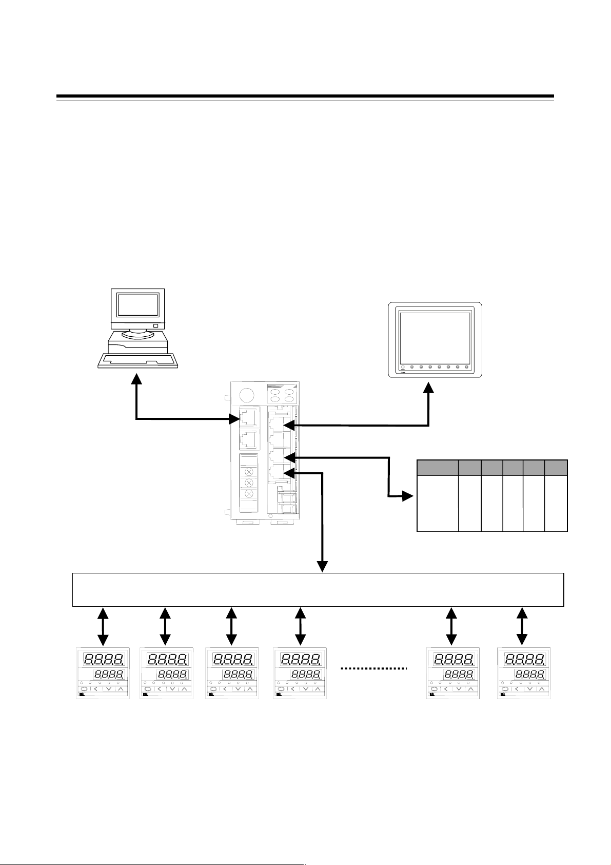
1. OUTLINE
This manual describes the specifications, mounting, wiring, connection, rotary switch setting and data
details of the COM-E.
1.1 Product Outline
The COM-E communication converter (hereinafter called the COM-E) is a product to connect the
RKC temperature controller with communication function and the programmable controller (PLC) .
Also, COM-E has the host communication port and the operation panel (MONITOUCH V6 series
made by Hakko Electronics Co., Ltd) port as the additional function.
Host computer
Communication converter
COM-E
RS-232C
RS-422
RS-485
or
RS-422
Junction terminals
CB100 CB100 CB100 CB100 CB100 CB100
RKC temperature controller
Up to 20
controllers
Operation panel
MONITOUCH V6 series
RS-422
Programmable controller
(PLC)
RKC temperature controller
IMS01C01-E7 1
Page 8

1. OUTLINE
Communication port
COM-E has the following four kinds of communication ports.
PLC communication port
COM-E connects the RKC temperature controller and PLC, and works as the communication protocol
converter. The PLC can connect one COM-E, using modular connector.
For a specification of connecting PLC, please also read the instruction manual for the used
PLC.
The RKC temperature controller communication port
This is RKC standard communication port used in the RKC temperature controller.
COM-E can connect the maximum twenty controllers in multi-drop wiring.
Host computer communication port
Host computer to be connected to host communication port can monitor, operate and control the
system. The host computer can connect one COM-E, using modular connector.
Operation panel communication port
COM-E connects the RKC temperature controller and operation panel, and works as the
communication protocol converter. The operation panel can connect one COM-E, using modular
connector.
For the operation panel communication, please also read the instruction manual for the V6
series of Hakko Electronics Co., Ltd.
2
IMS01C01-E7
Page 9

1.2 Confirmation of the Model Code
When unpacking your new instrument, please confirm that the following products are included.
If the product you received is not the one ordered, please contact RKC sales office or the agent.
Communication converter
COM-E-- 01
(1) (2)
(1) PLCs
01: YOKOGAWA PLC FA-M3 series
02: MITSUBISHI MELSEC A series (A, AnA, AnU type) / Q series / QnA series of PLCs
03: OMRON PLC SYSMAC CS1 series
(2) Corresponding to the RKC temperature controller
1. OUTLINE
01: REX-F400/REX-F700/REX-F900
CB100/CB400/CB500/CB700/CB900
SA200
A model code label is attached to the left side of the COM-E.
Modular connector cables (Sold separately)
W-BF-01-
“” are filled with cable length in mm. Please specify the length on your purchasing order. The
standard length is “3000.”
W-BF-01: Used to connect the RKC temperature controller, PLC, or the operation panel.
Terminal converter (Sold separately: Hakko Electronics Co., Ltd)
TC485
The TC485 is a converting connector for connecting the operation panel.
It is used together with the modular connector cable (W-BF-01-).
Cable to connect the host computer
The customer is requested to prepare a communication cable (cable with connector) for the COM-E to
be connected by the host computer.
IMS01C01-E7
3
Page 10
1. OUTLINE
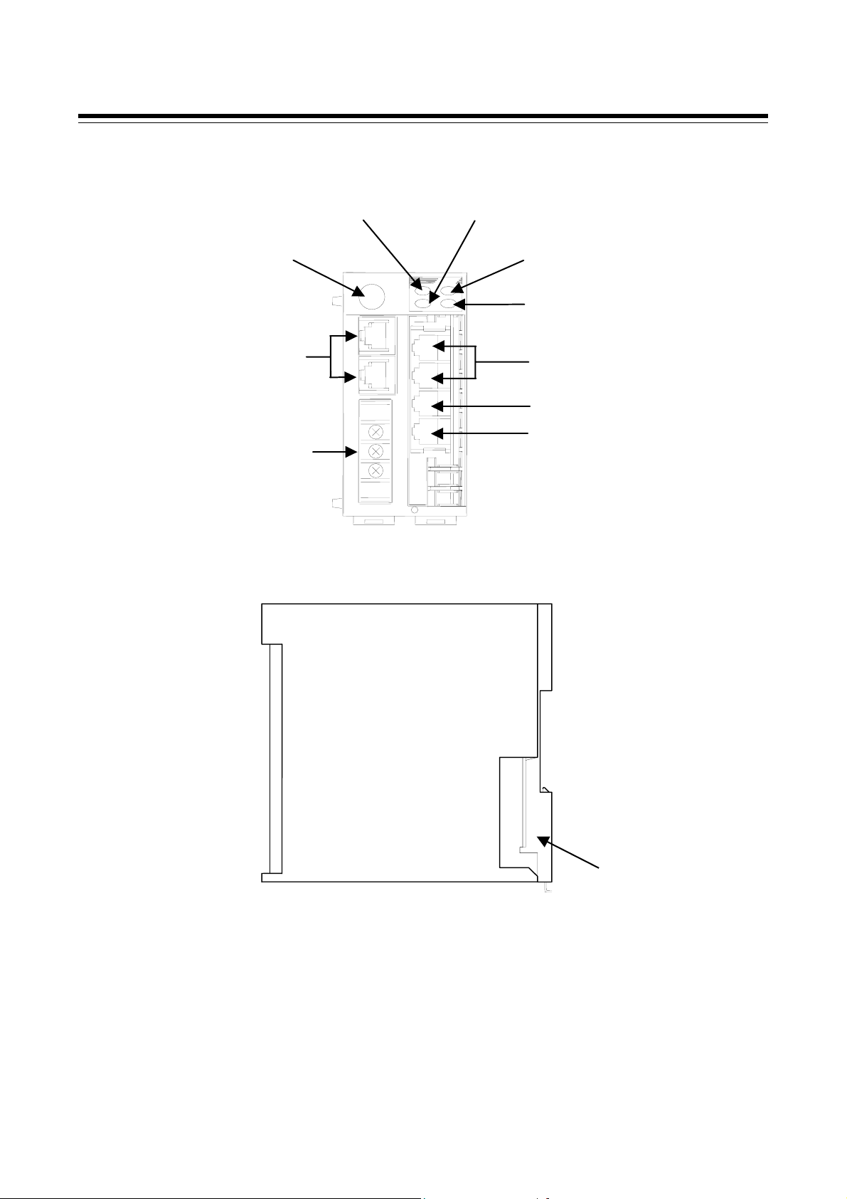
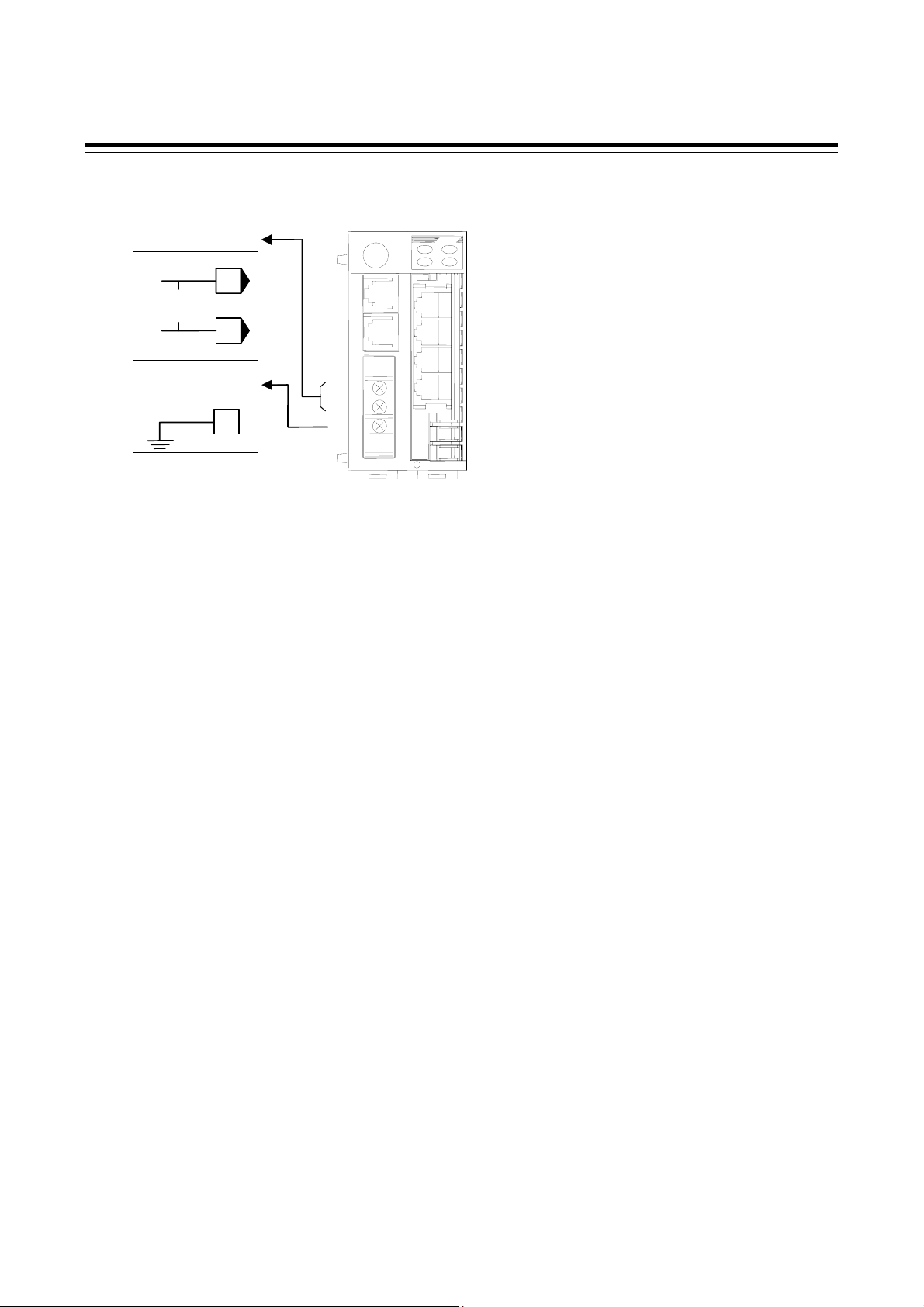
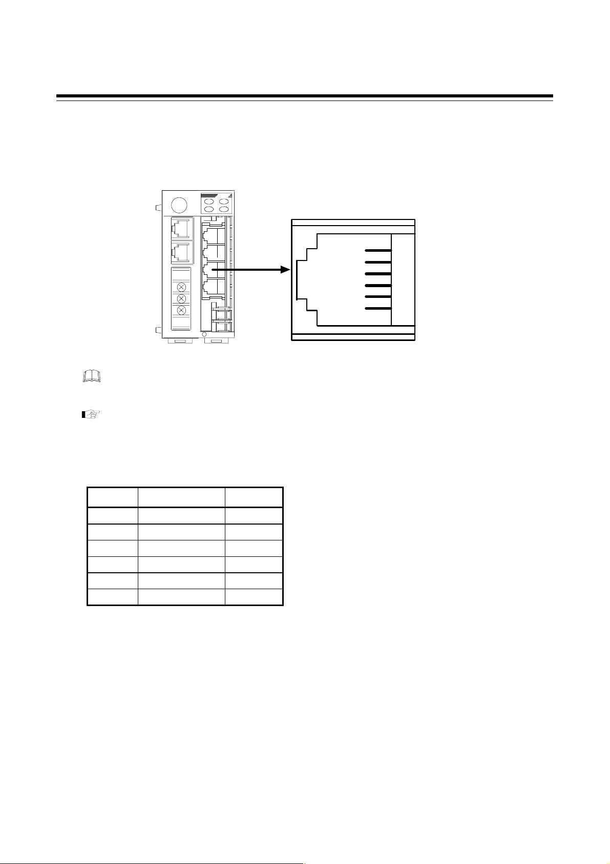
1.3 Parts Description
4.
Rotary switch
3.
Operation lamp 1
5.
Operation lamp 2
6.
Operation lamp 3
7. Operation lamp 4
2.
Modular connector COM1
1.
Power and ground terminals
8.
Modular connector COM2
9. Modular connector COM3
10.
Modular connector COM4
Front view
Module mainframe
Side view
11.
Mother block
4
IMS01C01-E7
Page 11

1. OUTLINE
No. Name Description
1 Power and ground terminals Power supply (24 V DC) and ground terminals
2 Modular connector COM1 Upper: Host communication port (for RS-232C)
Lower: Unused communication port
3 Rotary switch Register number selector of PLC
4 Operation lamp 1 (Yellow LED) ON: Host communication is operating.
5 Operation lamp 2 (Yellow LED) ON: Operation panel communication is operating.
6 Operation lamp 3 (Yellow LED) * ON: PLC communication is operating.
7 Operation lamp 4 (Yellow LED) * ON: Controllers communication is operating.
8 Modular connector COM2 Upper: Operation panel communication port (for RS-422A)
Lower: Unused communication port
9 Modular connector COM3 PLC communication port (for RS-422A)
10 Modular connector COM4 The RKC temperature controller communication port
11 Mother block Module DIN rail mounting connector
* LED flashes on and off regardless of presence of junction of PLC and temperature controller as soon
as the power is turned on.
IMS01C01-E7
5
Page 12

2. SPECIFICATIONS
PLC communication
Communication interface: Based on RS-422A, EIA standard
Communication method: Four-wire system, multi-drop connection
Protocol: PLC standard communication
Synchronous method: Start-stop synchronous type
Communication speed: 9600 bps, 19200 bps (Factory set value: 19200 bps)
(Selectable)
It is necessary that connect the operation panel when the setting is
changed.
Data bit configuration: Start bit: 1
Data bit: 8
Parity bit: Without or Even*
Stop bit: 1
*
For OMRON PLC SYSMAC CS1 series
Communication code: ASCII 7-bit code
Number of connection: One PLC per COM-E
The RKC temperature controller communication
Communication interface: Based on EIA standard RS-485 or EIA standard RS-422A *
*
Communication method: Two-wire system, multi-drop connection (RS-485)
Four-wire system, multi-drop connection (RS-422A)
Protocol: RKC standard communication
(Based on ANSI X 3.28 subcategory 2.5, B1)
Synchronous method: Start/stop synchronous type
Communication speed: 9600 bps, 19200 bps (factory set value: 19200 bps)
(Selectable)
It is necessary that connect the operation panel when the setting is
changed.
Data bit configuration: Start bit: 1
Data bit: 8
Parity bit: Without
Stop bit: 1
Communication code: ASCII 7-bit code
Number of connection: 20 controllers max. per COM-E
RS-422A is only for REX-F400/REX-F700/REX-F900
6 IMS01C01-E7
Page 13

2. SPECIFICATIONS
Host communication
Communication interface: Based on RS-232C, EIA standard
Communication method: RS-232C point-to-point connection
Protocol: Based on ANSI X3.28 subcategory 2.5, B1
Polling/selecting type
Error control: Horizontal parity
Synchronous method: Start-stop synchronous type
Communication speed: 9600 bps, 19200 bps (factory set value: 19200 bps)
(Selectable)
It is necessary that connect the operation panel when the setting is
changed.
Data bit configuration: Start bit: 1
Data bit: 8
Parity bit: Without
Stop bit: 1
Block length: 128 bytes or less
Communication code: ASCII 7-bit code
Control codes: ENQ (05H), EOT (04H), STX (02H), ETB (17H), ETX (03H),
ACK (06H), NAK (15H)
Codes in brackets ( ) are in hexadecimal.
Time out time: 3 seconds
Number of connection: One host computer per COM-E
Signal voltage and Logic: RS-232C
Signal voltage Logic
+ 3V or more 0 (Space status)
− 3V or less 1 (Mark status)
IMS01C01-E7 7
Page 14

2. SPECIFICATIONS
Operation panel communication
Communication interface: Based on RS-422A, EIA standard
Communication method: Four-wire system, multi-drop connection
Protocol: Based on MITSUBISHI AnA communication protcol
Synchronous method: Start-stop synchronous type
Communication speed: 9600 bps, 19200 bps, 38400 bps (factory set value: 19200 bps)
(Selectable)
It is necessary that connect the operation panel when the setting is
changed.
Data bit configuration: Start bit: 1
Data bit: 8
Parity bit: Without
Stop bit: 1
Communication code: ASCII 7-bit code
Number of connection: One operation panel per COM-E
Power supply
Power supply voltage: 21.6 to 26.4 V DC (Rating: 24V DC)
Ripple noise: 10 % or less (peak to peak)
Current consumption: 85 mA max. (24 V DC)
Diagnostic functions
Check item: ROM/RAM check
Watchdog timer
If error occurs in self-diagnosis, the message is displayed on the operation
panel display.
Data storage functions
Memory backup: Lithium battery for RAM backup, approximate 10 years life for data
retention.
*
and storage and operating environments.
However, the above life differs depending on the product storage period,
8
IMS01C01-E7
Page 15

2. SPECIFICATIONS
Calendar functions
Precision: Within ± 2.3 seconds per day
Setting method: Time set with the operation panel screen
Display: Western (Gregorian) calendar year, month, day, day of the week,
hour, minute display
The operation panel is necessary for the use of calendar functions.
General specifications
Insulation resistance: Between power and ground terminals: 20 MΩ or more at 500 V DC
Between output and ground terminals: 20 MΩ or more at 500 V DC
Withstand voltage: Between power and ground terminals: 1 minute at 1500 V AC
Between output and ground terminals: 1 minute at 1000 V AC
Withstand noise: 1500 V (peak to peak)
Pulse width: 1 µs
Rise time: 1 ns
By noise simulator
Ambient temperature range: 0 to 50 °C
Ambient humidity range: 45 to 85 % RH (Non condensing)
Ambient operating atmosphere:
There should be neither corrosive gases nor much dust.
Storage temperature range: −10 to +60 °C
Storage humidity range: 95 % RH or less (Non condensing)
Dimensions: 48 (W) × 96 (H) × 100 (D) mm
Weight: Approx. 300 g
IMS01C01-E7
9
Page 16

3. MOUNTING
To prevent electric shock or instrument failure, always turn off the power
before mounting or removing the instrument.
WARNING
!
3.1 Mounting Environment
(1) This instrument is intended to be used under the following environmental conditions. (IEC61010-1)
[OVERVOLTAGE CATEGORY II, POLLUTION DEGREE 2]
(2) Avoid the following when selecting the mounting location:
Ambient temperature less than 0 °C or more than 50 °C.
Ambient humidity of less than 45 % or more than 85 % RH.
Rapid changes in ambient temperature which may cause condensation.
Corrosive or inflammable gases.
Direct vibration or shock to the mainframe.
Water, oil, chemicals, vapor or steam splashes.
Excessive dust, salt or iron particles.
Excessive induction noise, static electricity, magnetic fields or noise.
Direct air flow from an air conditioner.
Exposure to direct sunlight.
Excessive heat accumulation.
10 IMS01C01-E7
Page 17

A
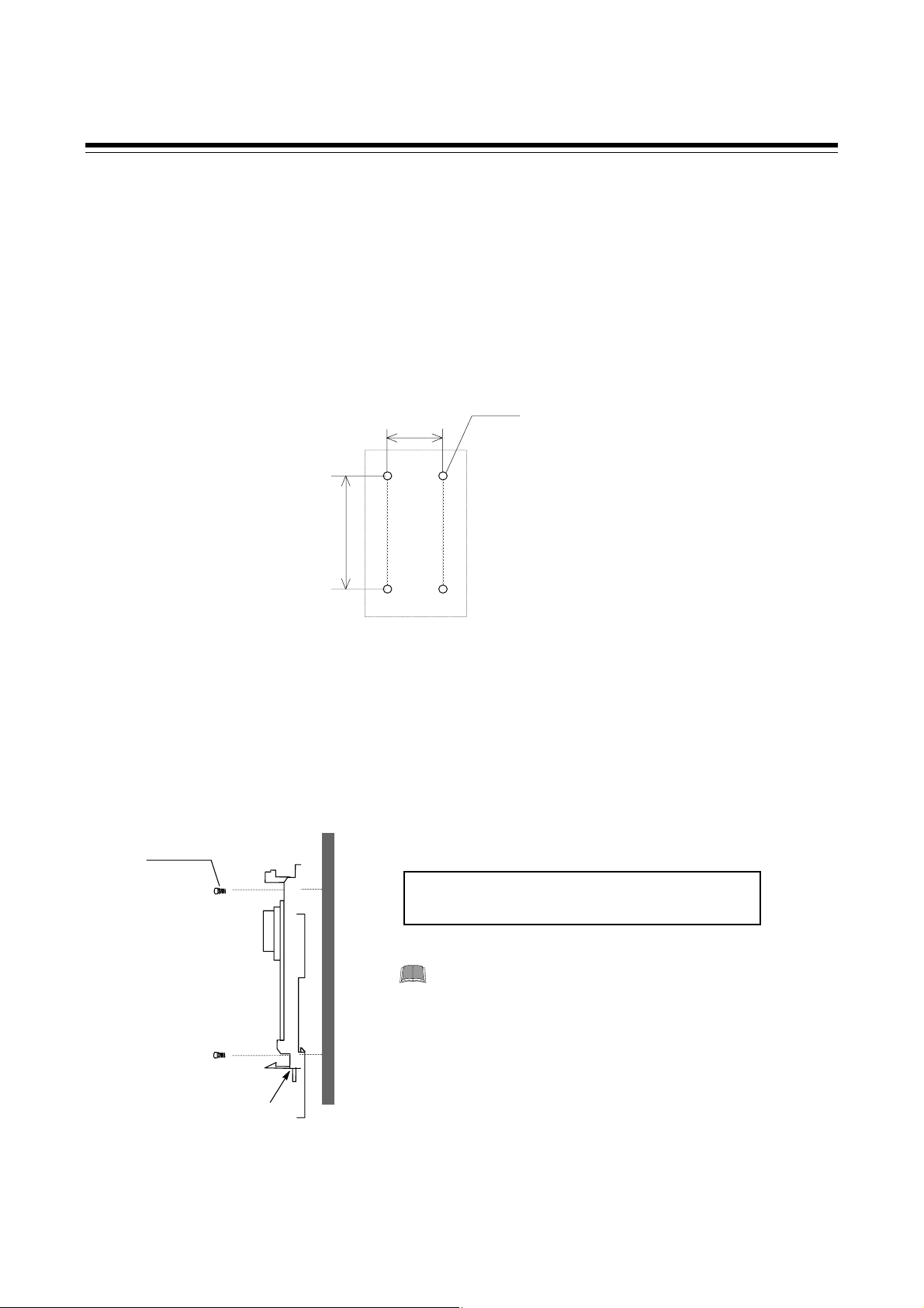
3.2 Dimensions
External dimensions
4
3. MOUNTING
(Unit: mm)
47.5
96
100
3.5
48
Module mounting depth (Mounting on the DIN rail)
The mounting depth of each module is 108 mm from the mounting surface inside the panel to the front
of the module with the module mounted on the DIN rail. However, when modular connector cables are
plugged in, additional depth is required.
pprox.
50
108
(Unit: mm)
DIN rail
IMS01C01-E7
11
Page 18
3. MOUNTING
3.3 Mounting the Mother Block
The mother block can be mounted to a panel or DIN rail.
Panel mounting directions
1. Refer to both the panel mounting dimensions below and the external dimensions in previous
section when selecting the location.
(Unit: mm)
4-M3
24
77
2. Remove the module from the mother block. For details of removing the module, see
3.5 Removing the module (P. 14).
3. Connect the mother blocks together before tightening the screws on the panel.
(Customer must provide the set screws)
M3 × 10
Recommended tightening torque:
0.3 Nm (3 kgfcm)
When the mother block is mounted on the panel,
50 mm or more space is required at the top and
bottom of the mother block to attach the
module mainframe.
Mother block
12
IMS01C01-E7
Page 19

3. MOUNTING
DIN rail mounting directions
1. Remove the module mainframe from the mother block. For details of removing the module
mainframe, see 3.5 Removing the Module Mainframe (P. 14).
2. Pull down both locking devices at the bottom of the mother block.
3. Attach the top bracket of the mother block to the DIN rail and push the lower section into place
on the DIN rail. (B)
4. Slide the locking devices up to secure the mother block to the DIN rail. (C)
(A)
When the mother block is mounted on panel, 50 mm or more space is required at the
top and bottom of the mother block to attach the module mainframe.
Locking device
A
B
C
IMS01C01-E7
13
Page 20

3. MOUNTING
3.4 Mounting the Module Mainframe
It engages the module with the mother block that is mounted on DIN rail or a panel.
1. Place the module mainframe opening on top of the mother block tab. (A)
2. Snap the lower part of module mainframe on to the mother block. (B)
Opening at top of module
A snapping sound will be heard when module mainframe is securely connected to mother
block.
A
Tab at top of mother
B
3.5 Removing the Module Mainframe
To separate the module mainframe from the mother block, press the bottom on the module, lifting
upward, to release connection.
Mother block
Module mainframe
Press bottom of module
and lift upward to release
Module mainframe
Upper
section
Lower
section
Mother block
14
IMS01C01-E7
Page 21

4. WIRING
4.1 Wiring
To prevent electric shock or instrument failure, do not turn on the power until all
the wiring is completed.
CAUTIONS
Power supply wiring:
WARNING
!
Use a power supply is within the power supply voltage variation range.
For power supply wires, use twisted wires with low voltage drop.
Separate each of the instrument power supply line, input/output circuit power supply line,
equipment and motor power supply line, and operating circuit power supply line.
If a noise source is near the instrument and could affect the instrument, use a noise
filter.
− Shorten the distance between twisted power supply wire pitches. The shorter the
distance between the pitches, the more effective for noise reduction. In addition,
always ground noise filter.
− Always install the noise filter on the grounded panel. Also minimize the wiring distance
between the noise filter output side and instrument power supply terminals to ensure
the effectiveness of the noise filter.
− Do not connect fuses or switches on the wiring of the noise filter output side, since
these may reduce the effectiveness of the noise filter.
− To obtain a satisfactory noise filter effect, select the most suitable type after due
consideration of instrument power supply voltage and filter frequency characteristics.
To the instrument with power supply of 24 V, please be sure to supply the power from
SELV circuit.
Grounding wire wiring:
Ground the instrument separately from other equipment. The grounding resistance should
be 100 Ω or less. Use grounding wires with a cross section area of 2.0 mm
IMS01C01-E7 15
2
or more.
Page 22
4. WIRING
Power supply and ground wiring
Power terminals
DC +
24 V
Ground terminal
12
13
-
11
12
14
13
14
15
Terminal screw
Screw size: M3
Recommended tightening torque:
0.4 N⋅m (4 kgf⋅cm)
Power supply
21.6 to 26.4 V DC (Rating: 24V DC)
Ripple noise: less than 10 % (peak to peak)
Ground
Ground the instrument separately from other equipment. The grounding resistance should be 100 Ω or
less. Use grounding wires with a cross section area of 2.0 mm
2
or more.
16
IMS01C01-E7
Page 23

(B)
4.2 Connection
To prevent electric shock or instrument failure, turn off the power before
connecting or disconnecting the instrument and peripheral equipment.
4.2.1 Connection to PLC
Customer is requested to prepare a communication cable fit for the COM-E to be connected by PLC.
YOKOGAWA FA-M3 series
WARNING
!
4. WIRING
Pin layout of COM3
COM-E
The 6-pin type modular connector should be used for the connection to the COM-E.
Pin number and signal name (RS-422A)
(Recommended manufacturer and model : Hirose Electric, TM4P-66P)
The details of the connectable connector for the PLC please also read the instruction manual
for the used PLC.
Pin No. Signal Name Symbol
PLC communication port : COM3
T (A)
T (B)
SG 3
R
R (A)
SG
1
2
4
5
6
1 Send Data T (A)
2 Send Data T (B)
3 Signal Ground SG
4 Receive Data R (B)
5 Receive Data R (A)
IMS01C01-E7
6 Signal Ground SG
17
Page 24
4. WIRING
(
)
Diagram of RS-422A communication cable wiring
COM-E
1
T (A)
T (B)
SG
R (B)
R (A)
SG
2
3
4
5
6
RS-422A
Paired wire
Twisted pair wire
with shield
YOKOGAWA FA-M3 series
PLC
RDA
RDB
SG
SDB
SDA
Modular connector cable W-BF-01 * can use to connect PLC.
*
Shields of the cable are connected to SG (No. 6 pin) of the COM-E connector.
A wiring example when using our W-BF-01 connection cable is shown in the following.
Cable type: W-BF-01-3000 (RKC product, Sold separately)
[Standard cable length: 3 m]
Orange
YOKOGAWA FA-M3 series
R(B)
PLC
SDB
White
R(A)
SDA
W-BF-01
Black
Blue
Red
T(B)
T(A)
SG
RDB
RDA
SG
18
IMS01C01-E7
Page 25
)
MITSUBISHI MELSEC A series (A, AnA, AnU types)/Q series/QnA series
Pin layout of COM3
COM-E
PLC communication port : COM3
4. WIRING
The 6-pin type modular connector should be used for the connection to the COM-E.
(Recommended manufacturer and model : Hirose Electric, TM4P-66P)
The details of the connectable connector for the PLC please also read the instruction manual
for the used PLC.
Pin number and signal name (RS-422A)
Pin No. Signal Name Symbol
1 Send Data T (A)
2 Send Data T (B)
3 Signal Ground SG
4 Receive Data R (B)
5 Receive Data R (A)
6 Signal Ground SG
T (A)
T (B)
1
2
SG 3
R (B
R (A)
SG
4
5
6
IMS01C01-E7
19
Page 26
4. WIRING
A
A
Diagram of RS-422A communication cable wiring
RS-422A
COM-E
T (A)
T (B)
SG
R (B)
R (A)
SG
1
2
3
4
5
6
Paired wire
Twisted pair wire
(with shield)
MITSUBISHI MELSEC
A series (A, AnA, AnU types)/
Q series/QnA series
PLC
RDB
RDA
SG
SD
SDB
For connection with the COM-E, use the Computer link unit.
Cannot connect to the PLCs CPU-port.
As communication protocol, the type 4 protocol control procedure only for
MITSUBISHI is used.
When preparing a cable of connecting the Computer link unit belonging to the
MITSUBISHI MELSEC A series of PLCs to our COM-E, cross each pair of wires as
shown in Fig.4-14 as the A and B terminal positions on their terminal boards are not
symmetrical.
Example: Connect the COM-E T (A) send data terminal to the RDB receive data terminal
on the Computer link unit belonging to the MITSUBISHI MELSEC A series of
PLCs.
Modular connector cable W-BF-01 * can use to connect PLC.
*
Shields of the cable are connected to SG (No. 6 pin) of the COM-E connector.
A wiring example when using our W-BF-01 connection cable is shown in the following.
Cable type: W-BF-01-3000 (RKC product, Sold separately)
[Standard cable length: 3 m]
Orange
R(B)
White
W-BF-01
Black
Blue
Red
R(A)
T(B)
T(A)
SG
MITSUBISHI MELSEC
A series (A, AnA, AnU types)/
Q series/QnA series
20
PLC
SDA
SDB
RD
RDB
SG
IMS01C01-E7
Page 27
(B)
OMRON SYSMAC CS1 series
Pin layout of COM3
COM-E
4. WIRING
PLC communication port : COM3
The 6-pin type modular connector should be used for the connection to the COM-E.
Pin number and signal name (RS-422A)
(Recommended manufacturer and model : Hirose Electric, TM4P-66P)
The details of the connectable connector for the PLC please also read the instruction manual
for the used PLC.
Pin No. Signal Name Symbol
1 Send Data T (A)
2 Send Data T (B)
3 Signal Ground SG
4 Receive Data R (B)
5 Receive Data R (A)
6 Signal Ground SG
T (A)
T (B)
SG 3
R
R (A)
SG
1
2
4
5
6
IMS01C01-E7
21
Page 28

4. WIRING
(
)
A
Diagram of RS-422A communication cable wiring
COM-E
1
T (A)
T (B)
SG
R (B)
R (A)
SG
2
3
4
5
6
RS-422A
Paired wire
Twisted pair wire
with shield
OMRON SYSMAC CS1 series
PLC
RDA
RDB
SDB
SDA
Modular connector cable W-BF-01 * can use to connect PLC.
*
Shields of the cable are connected to SG (No. 6 pin) of the COM-E connector.
A wiring example when using our W-BF-01 connection cable is shown in the following.
Cable type: W-BF-01-3000 (RKC product, Sold separately)
[Standard cable length: 3 m]
OMRON SYSMAC CS1 series
PLC
Orange
White
R(B)
R(A)
SDB
SDA
W-BF-01
Black
Blue
Red
T(B)
T(A)
SG
RDB
RD
22
IMS01C01-E7
Page 29

•
•
4.2.2 Connection to the RKC temperature controller
For the connection cable, use the RKC product (Sold separately).
Cable type: W-BF-01-3000 [Standard cable length: 3 m] (RKC product, Sold separately)
When using one RKC temperature controller
COM-E
Connection cable
W-BF-01
RKC temperature controller
PV
SV
R/S
CB100
CB100
4. WIRING
When the communication interface of RKC temperature controller is RS-422A
W-BF-01
Connect according to the label names as they are without crossing the wires.
Orange
White
Black
Blue
Red
R(B)
R(A)
T(B)
T(A)
SG
RKC temperature
controller terminals
R (B)
R (A)
T (B)
T (A)
SG
When the communication interface of RKC temperature controller is RS-485
In RS-485, connect the signal line T (A) and R (A). And, connect the signal line T (B) and R (B) in
the same way.
W-BF-01
Orange
Black
White
Blue
Red
R(B)
T(B)
R(A)
T(A)
SG
When using the RKC temperature controller, always set addresses of them to 0.
When using the RKC temperature controller, set communication interval time period
for them to 25 ms or more.
For details on setting communication with the RKC temperature controller, see the
Communications instruction manual for the RKC temperature controller.
RKC temperature
controller terminals
T/R (B)
T/R (A)
SG
IMS01C01-E7
23
Page 30

4. WIRING
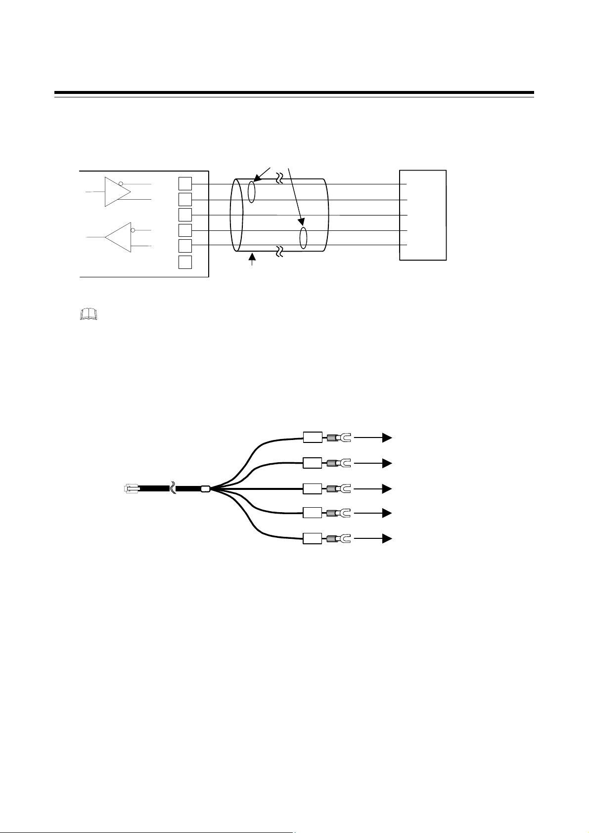
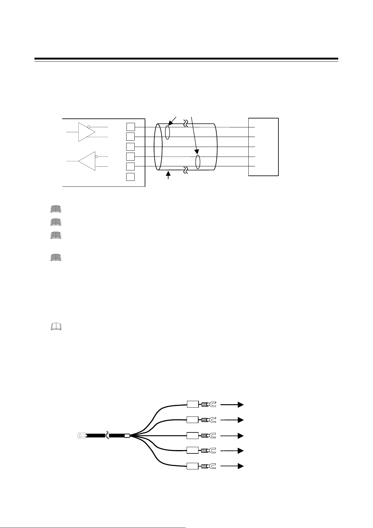
When using two or more RKC temperature controllers
COM-E
When the communication interface of RKC temperature controller is RS-422A
W-BF-01
Connection cable
W-BF-01
Junction terminals
Orange
White
Black
Blue
Red
R(B)
R(A)
T(B)
T(A)
SG
RKC temperature controllers
PV
SV
R/S
CB100
PV
SV
R/S
CB100
Up to 20 controllers
Junction terminals
RKC temperature
controller terminals
R (B)
R (A)
T (B)
T (A)
SG
Connect according to the label names as they are without crossing the wires.
24
R (B)
R (A)
T (B)
T (A)
SG
Up to 20 controllers
Continued on the next page.
IMS01C01-E7
Page 31

•
•
Continued from the previous page.
When the communication interface of RKC temperature controller is RS-485
In RS-485, connect the signal line T (A) and R (A). And, connect the signal line T (B) and R (B) in
the same way.
W-BF-01
Orange
Black
White
Blue
Red
R(B)
T(B)
R(A)
T(A)
SG
Junction terminals
RKC temperature
controller terminals
4. WIRING
T/R (B)
T/R (A)
SG
T/R (B)
T/R (A)
SG
Up to 20 controllers
When using the RKC temperature controller, always use their addresses from address
number 0 in succession.
When using the RKC temperature controller, set communication interval time period
for them to 25 ms or more.
Prepare cables for connecting the junction branch box to the temperature controllers on your
side. (No cables included in the instrument)
For details on setting communication with the RKC temperature controller, see the
Communications instruction manual for the RKC temperature controller.
IMS01C01-E7
25
Page 32

4. WIRING
(B)
(B)
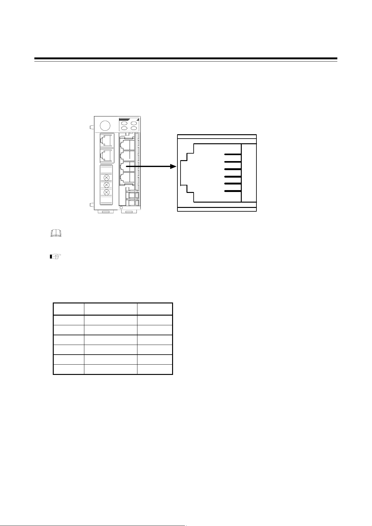
Pin layout of COM4
COM-E
RKC temperature controller
communication port: COM4
The 6-pin type modular connector should be used for the connection to the COM-E.
(Recommended manufacturer and model : Hirose Electric, TM4P-66P)
Pin number and signal name (RS-422A)
Pin No. Signal Name Symbol
1 Receive Data R (A)
2 Receive Data R (B)
3 Signal Ground SG
4 Send Data T (B)
5 Send Data T (A)
6 Signal Ground SG
R (A)
R
SG 3
T
T (A)
SG
1
2
4
5
6
26
IMS01C01-E7
Page 33

Diagram of communication cable wiring
RS-485
4. WIRING
COM-E
In RS-485, connect the signal line T (A) and R (A). And, connect the signal line T (B) and
R (B) in the same way.
RS-422A
R (A)
R (B)
SG
T (B)
T (A)
SG
COM-E
RS-485
Paired wire
1
2
3
RKC temperature
controller
T/R (A)
T/R (B)
SG
4
5
6
Twisted pair wire
(with shield)
RS-422A
Paired wire
RKC temperature
controller
R (A)
R (B)
T (B)
T (A)
SG
SG
1
2
3
4
5
6
Twisted pair wire
(with shield)
T (A)
T (B)
SG
R (A)
R (B)
Modular connector cable W-BF-01 * can use to connect RKC temperature controller.
*
Shields of the cable are connected to SG (No. 6 pin) of the COM-E connector.
IMS01C01-E7 27
Page 34

4. WIRING
4.2.3 Connection to the host computer
Customer is requested to prepare a communication cable fit for the COM-E to be connected by the
host computer.
Pin layout of COM1
COM-E
Host communication port:
COM1
Pin number and signal name (RS-232C)
Pin No. Signal Name Symbol
1
Unused
2 Send Data SD (TXD)
3 Signal Ground SG
4 Receive Data RD (RXD)
5
6 Signal Ground SG
Unused
Diagram of RS-232C communication cable wiring
Unused 1
SD 2
SG 3
RD 4
Unused 5
SG 6
28
COM-E
SD (TXD)
SG (GND)
RD (RXD)
SG (GND)
RS-232C
2
3
4
6
Shielded wire
Host Computer
SD (TXD)
SG (GND)
RD (RXD)
*
RS (RTS)
CS (CTS)
* Short circuit between RS-CS
pin in the connector.
IMS01C01-E7
Page 35

4.2.4 Connection to operation panel
For the connection cable, use the RKC product (Sold separately).
Cable type: W-BF-01-3000 [Standard cable length: 3 m]
COM-E
RS-422A
Terminal
converter
4. WIRING
Operation panel (front)
MONITOUCH V6 series
Connection cable
W-BF-01
TC485
Cable type: W-BF-01-3000 (RKC product, Sold separately)
[Standard cable length: 3 m]
Terminal converter
Orange
R(B)
White
Black
Blue
Red
R(A)
T(B)
T(A)
SG
W-BF-01
For connection of the operation panel with the connection cable, the TC485 terminal
converter connector (sold separately: Hakko Electronics Co., Ltd) is required.
The details of the connectable connector for the operation panel, please also read the
instruction manual for the V6 series of Hakko Electronics Co., Ltd.
TC485
SD
+
SD
-
RD
+
RD
-
SG
IMS01C01-E7
29
Page 36

4. WIRING
(
)
Pin layout of COM2
COM-E
Operation panel
communication port: COM2
The 6-pin type modular connector should be used for the connection to the
(Recommended manufacturer and model: Hirose Electric, TM4P-66P)
The details of the connectable connector for the operation panel, please also read the
instruction manual for the V6 series of Hakko Electronics Co., Ltd.
Pin number and signal name (RS-422A)
Pin No. Signal Name Symbol
R (A)
R (B)
SG
T (B)
T (A)
SG
1
2
3
4
5
6
COM-E.
1 Receive Data R (A)
2 Receive Data R (B)
3 Signal Ground SG
4 Send Data T (B)
5 Send Data T (A)
6 Signal Ground SG
Diagram of RS-422A communication cable wiring
COM-E
R (A)
R (B)
T (B)
T (A)
SG
SG
1
2
3
4
5
6
Modular connector cable W-BF-01 * can use to connect the operation panel.
Shields of the cable are connected to SG (No. 6 pin) of the COM-E connector.
*
RS-422A
Paired wire
Twisted pair wire
with shield
Operation panel
-SD
+SD
SG
+RD
-RD
30
IMS01C01-E7
Page 37

5. PLC COMMUNICATION
5.1 Rotary Switch Setting
The COM-E rotary switch can set the PLC register area.
For this setting, use a small blade screwdriver.
COM-E
It is prohibited to set the rotary switch to the “B” position.
Select the setting of rotary switch after confirming the PLC register area.
Rotary switch
0
1
2
F
3
E
4
D
5
C
6
B
7
A
9
8
Setting range: 0 to F (hexadecimal)
Factory set value: 8: OMRON SYSMAC CS1 series
9: MITSUBISHI MELSEC A series/
Q series/QnA series
A: YOKOGAWA FA-M3 series
IMS01C01-E7
31
Page 38

5. PLC COMMUNICATION
5.2 PLC Setting
5.2.1 YOKOGAWA FA-M3 series
Please turn on number 1 only and turn off numbers 2 to 8 of the data format
configuration switch, which there is in personal computer link module F3LC11-2N
belonging to the YOKOGAWA FA-M3 series of PLCs. When the data format
configuration switch turn on number 1 only and turn off numbers 2 to 8 , these come to
the following data format.
• Data bit: 8
• Parity bit: Without
• Stop bit: 1
• Checksum: Without
• Final character specification: Without
• Protection function: Without
For details on setting with the PLC, please also read the instruction manual for the used PLC.
Rotary switch Number of COM-E and PLC register area
Rotary
switch No.
PLC register area Remarks
0 Area available in D register D1000 to D1399
1 Area available in D register D1500 to D1899
2 Area available in D register D2000 to D2399
3 Area available in D register D2500 to D2899
4 Area available in D register D3000 to D3399
5 Area available in D register D3500 to D3899
6 Area available in D register D4000 to D4399
7 Area available in D register D4500 to D4899
8 Area available in D register D5000 to D5399
9 Area available in D register D5500 to D5899
A Area available in D register D6000 to D6399
B Interdict from setting (the default mode)
C Area available in W register W0000 to W0399 Not usable
D Area available in W register W0500 to D0899
E Area available in D register D0000 to D0399 Not usable
F Area available in D register D0500 to D0899
32
IMS01C01-E7
Page 39

5. PLC COMMUNICATION
5.2.2 MITSUBISHI MELSEC A series (A, AnA, AnU types)/Q series/QnA
series
Please set the Computer link unit belonging to the MITSUBISHI MELSEC series of
PLCs as follows.
• Protocol: MITSUBISHI MELSEC series special protocol type 4
• Data bit: 8
• Parity bit: Without
• Stop bit: 1
• Sum check code: Provided
• Writing during RUN: ON
• Station number: 00
• PC number: FF
For details on setting with the PLC, please also read the instruction manual for the used PLC.
Rotary switch Number of COM-E and PLC register area
Rotary
switch No.
0
1
2
3
4
5
6
7
8
9
A
B
C
PLC register area Remarks
Area available in D register D1000 to D1399
Area available in D register D1500 to D1899
Area available in D register D2000 to D2399
Area available in D register D2500 to D2899
Area available in D register D3000 to D3399
Area available in D register D3500 to D3899
Area available in D register D4000 to D4399
Area available in D register D4500 to D4899
Area available in D register D5000 to D5399
Area available in D register D5500 to D5899
Area available in D register D6000 to D6399
Interdict from setting (the default mode)
Area available in W register W0000 to W018F
Corresponding to AnA/AnU
type CPU, Q series and QnA
series.
Corresponding to the instrument
model which uses the QR/QW
command as a communication
command.
Corresponding to A type CPU. *
D
E
F
* A type CPU model code: A1S, A1SJ, A0J2H, A1, A1N, A2 (S1), A2N (S1), A2S, A2A (S1), A2U, A2US,
A2C, A52G, A3, A3N, A3A, A3U, A4U, A3H, A3M, A73 or A7LMS-F
IMS01C01-E7
Area available in W register W0200 to D038F
Area available in D register D0000 to D0399
Area available in D register D0500 to D0899
Corresponding to the instrument
model which uses the WR/WW
command as a communication
command.
33
Page 40

5. PLC COMMUNICATION
5.2.3 OMRON SYSMAC CS1 series
Please set the CPU unit belonging to the OMRON SYSMAC CS1 series of PLCs as
follows.
• Serial communication mode: high-order link method
• Data bit: 8
• Parity bit: Provided (even)
• Stop bit: 1
• Unit number (Model number) : 00
For details on setting with the PLC, please also read the instruction manual for the used PLC.
Rotary switch Number of COM-E and PLC register area
Rotary
switch No.
PLC register area Remarks
0 Area available in D register D1000 to D1399
1 Area available in D register D1500 to D1899
2 Area available in D register D2000 to D2399
3 Area available in D register D2500 to D2899
4 Area available in D register D3000 to D3399
5 Area available in D register D3500 to D3899
6 Area available in D register D4000 to D4399
7 Area available in D register D4500 to D4899
8 Area available in D register D5000 to D5399
9 Area available in D register D5500 to D5899
A Area available in D register D6000 to D6399
B Interdict from setting (the default mode)
C Area available in D register D7000 to D7399
D Area available in D register D7500 to D7899
E Area available in D register D0000 to D0399
F Area available in D register D0500 to D0899
34
IMS01C01-E7
Page 41

5. PLC COMMUNICATION
5.3 The RKC Temperature Controller Setting
Please set the RKC temperature controller side as follows.
CB100/CB400/CB500/CB700/CB900
Setting items Description
Communication speed 19200 bps
Data bit 8
Stop bit 1
Parity bit Without
Communication interval time 15 or more (25 ms or more)
Device address Always use their addresses from address number 0 in
succession.
REX-F400/REX-F700/REX-F900
Setting items Description
Communication speed 19200 bps
Data bit 8
Stop bit 1
Parity bit Without
Communication interval time 25 ms or more
Device address Always use their addresses from address number 0 in
succession.
SA200
Setting items Description
Communication speed 19200 bps
Data bit 8
Stop bit 1
Parity bit Without
Communication interval time 25 ms or more
Device address Always use their addresses from address number 0 in
succession.
For details on setting communication with the RKC temperature controller, see the
Communications instruction manual
for the RKC temperature controller.
IMS01C01-E7
35
Page 42

5. PLC COMMUNICATION
5.4 Communication Data
5.4.1 Request command and data transfer
Data transfer between the PLC and RKC temperature controller are excuted by the request
command (Register area No. 20).
Request command “0: Monitor”
Command which requests the RKC temperature controller to write data items such as temperature
measured values, etc. (attribute: RO) to the PLC side. The COM-E always repeats data writing until
“1: Setting” or “2: Set value monitor” is set to the request command. The COM-E communication
status is set to “1: Writing on monitor data” during data transfer.
Data transfer procedures
[Example]
• Set “0: Monitor” to the request command on the PLC side.
• If the request command is set, the COM-E writes our temperature controller data items such as
temperature measured values, etc. (attribute: RO) into the PLC.
• The COM-E communication status is set to “1: Writing on monitor data” during data transfer.
PLC
1. The COM-E reads the request
command “0: Monitor” from the PLC.
COM-E
The COM-E always repeats
data read.
RKC temperature
controller
2. The COM-E writes RKC temperature
controller data items such as
temperature measured values, etc.
into the PLC.
Request command “1: Setting”
This is the command of making a request to our temperature controller for writing data items such as
temperature set values, etc. (attribute: RW) set to the resister on the PLC side (memory).
Data transfer procedures
[Example]
• Data items such as temperature set values, etc. (attribute: RW) are set to the resister on the PLC
side (memory).
• Set “1: Setting” to the request command on the PLC side.
Continued on the next page.
36
IMS01C01-E7
Page 43

5. PLC COMMUNICATION
Continued from the previous page.
•
If the request command is set, the COM-E starts reading data items such as temperature set values,
etc. (attribute: RW) on the PLC side. The COM-E communication status is set to “2: Reading out
setting data” during data read on the PLC side.
• If the COM-E finishes reading data items from the PLC, it starts writing the data items read to our
temperature controller. The COM-E communication status is set to “2: Reading out setting data”
even during data write into our temperature controller.
• After the data is transferred, the request command and COM-E communication status returns
to “0: Monitor” and “1: Writing on monitor data,” respectively.
PLC
1. The COM-E reads the request
command “1: Setting” from the PLC.
COM-E
3. The COM-E writes data
items read from the PLC
side.
RKC temperature
controller
2. The COM-E reads data items such as
temperature set values, etc.
on the PLC side.
Request command “2: Set value monitor”
Command which requests the RKC temperature controller to write data items such as temperature set
values, etc. (attribute: RW) to the PLC side.
Data transfer procedures
[Example]
• Set “2: Set value monitor” to the request command on the PLC side.
• If the request command is set, the COM-E writes our temperature controller data items such as
temperature set values, etc. (attribute: RW) into the PLC.
The COM-E communication status is set to “3: Writing on setting data” during data transfer.
• After the data is transferred, the request command and COM-E communication status returns
to “0: Monitor” and “1: Writing on monitor data,” respectively.
PLC
1. The COM-E reads the request
command “2: Set value monitor” from
the PLC.
COM-E
The COM-E always repeats
data read.
RKC temperature
controller
IMS01C01-E7
2. The COM-E writes RKC temperature
controller data items such as temperature
set values, etc. into the PLC.
37
Page 44

5. PLC COMMUNICATION
5.4.2 Communication status check
The communication status between the PLC and COM-E is confirmed by the COM-E communication
status (Register area No. 21).
The COM-E always writes data on the COM-E communication status into the PLC.
COM-E communication status “0: Communication failure”:
“0: Communication failure” represents that communication between the COM-E and PLC is abnormal.
If communication between the COM-E and PLC is normal, the COM-E communication status
always becomes 1, 2, or 3.
COM-E communication status “1: Writing on monitor data”:
“1: Writing on monitor data” represents that data items such as temperature measured values, etc.
(attribute: RO) are being written into the PLC.
COM-E communication status “2: Reading out setting data”:
“2: Reading out setting data” represents that data items such as temperature set values, etc. (attribute:
RW) are being read from the PLC.
COM-E communication status “3: Writing on setting data”:
“3: Writing on setting data” represents that data items such as temperature set values, etc. (attribute:
RW) are being written into the PLC.
Communication status check procedures
[Example]
When the COM-E communication status is “1: Writing on monitor data”
1. “0: Communication failure” is set to the register on the PLC side (COM-E communication
status).
Conduct this setting only when checking the communication status.
2. After setting, take appropriate wait time.
Wait time differs depending on the connectable number of our temperature controllers.
It is about 1 second/controller.
3. After a lapse of wait time, confirm that the value in the register on the PLC side (COM-E
communication status) is “1: Writing on monitor data.”
38
IMS01C01-E7
Page 45

5.4.3 Caution for handling communication data
(1) The alarm status in each channel is expressed for each bit.
[b0] : Unused
[b1] : Unused
[b2] : Alarm 1 status (0: OFF 1: ON)
*
[b3] : Alarm 2 status or HBA (Heater break alarm) status
[b4] : Burnout status (0: OFF 1: ON)
[b5] : Unused
[b6] : Unused
[b7] : Unused
[b8] : Error flag (0: Normality 1: Abnormality of instrument or communication)
[b9] to [b15] : Unused
*
Remove REX-F400/REX-F700/REX-F900
(0: OFF 1: ON)
5. PLC COMMUNICATION
[Example] The following expressions are when alarm 1 is turned on.
• Binary digit: 00000000 00000100
• Hexadecimal numeral: 0004H
• Decimal numeral: 4
(2) The data type is treated as binary data with a sign and without a decimal point. For this reason,
carefully express and set the data.
[Example] Proportional band setting
Initial value of internal data: 3.0
Communication data: 30
(3) Any item whose attribute is RO (Read only) is always written to the PLC from the
COM-E.
During data write, “1: Writing on monitor data” is written to “COM-E communication status.”
(The RKC temperature controller
→ COM-E → PLC)
(4) Any item whose attribute is R/W (Read and Write) is read only when “Request command” is set to
“1: Setting.”
→ COM-E → The RKC temperature controller)
(PLC
(5) Any item whose attribute is R/W (Read and Write) is written only when “Request command” is set
to “2: Set value monitor.” After finish writing, “COM-E communication status” is set to “1:
Writing on monitor data”, “Request command” is set to “0: Monitor.”
(The RKC temperature controller
→ COM-E → PLC)
(6) The autotuning (AT) function is activated when “AT startup/stop” is set to “1: Autotuning (AT)
startup” and “A request for reading out set value” is set to “1: Reading out set value.” After the
autotuning (AT) function is finished, the
COM-E sets “2: Writing on set value” to “A request for
reading out set value” to write each set value to the PLC. At this time, “AT startup/stop” returns
to “0: Autotuning (AT) end or stop” to change the PID constants.
IMS01C01-E7
39
Page 46

5. PLC COMMUNICATION
5.5 Communication Items List
5.5.1 Reference to communication items list
This communication items list summarizes the register area numbers of the PLC, communication items,
data, setting ranges and attributes.
(1) (2) (3) (4) (5)
Register
area No.
Communication items Data Setting range Attribute
1
2 Alarm set value 1 20
3 Alarm set value 2 20
(1) Register area No.: It is written in register area numbers of the PLC that can be used with each
communication item. Check the register number which will be actually
used in
Before operation, always set “The total number of RKC temperature controllers” in
register area number 22 to the desired number.
(2) Communication items: It is written in each communication item
(3) Data: It is written in data of each communication item.
(4) Setting range: It is written in setting ranges of each communication item.
(5) Attribute: It is written in attributes of each communication item.
Never set any item whose attribute is RO (Read only).
Set value (SV)
5.6 Table of register area numbers vs. register numbers (P. 49).
20: The maximum number of RKC temperature controllers which can be
connected to the
1: It is a common data of RKC temperature controllers which be
connected to the
ROs indicate monitor items which are read from the RKC temperature
controller by the PLC .
R/Ws indicate items which are read from and written to the RKC
temperature controller by the PLC.
20 Within input range R/W
Temperature input
Process alarm, deviation alarm,
SV alarm:
-1999 to +9999
-199.9 to +999.9
Voltage/ current inputs
Deviation alarm: -span to +span
(Within 9999)
Process alarm, SV alarm:
Within input range
COM-E.
COM-E.
°C [°F] or
°C [°F]
R/W
R/W
40
IMS01C01-E7
Page 47

5.5.2 CB100/CB400/CB500/CB700/CB900
(Attribute RO: Read only R/W: Read and Write)
5. PLC COMMUNICATION
Register
area No.
1
2 Alarm 1 set value 20
Communication items Data Setting range Attribute
Set value (SV)
20 Within input range R/W
Temperature input
Process alarm, deviation alarm,
SV alarm:
−1999 to +9999 °C [°F] or
−199.9 to +999.9 °C [°F]
3 Alarm 2 set value 20
Voltage/ current inputs
Deviation alarm:
−span to +span
(Within 9999)
Process alarm, SV alarm:
Within input range
4 Heater break alarm (HBA) 1
set value
1
20 0.0 to 100.0 A R/W
5 RUN/STOP function 20 0: RUN
1: STOP
6 User unusable province
7 User unusable province
8 Overlap/Deadband
2
20
- - -
- - -
Temperature input:
−10 to +10 °C [°F] or
−10.0 to +10.0 °C [°F]
Voltage/current inputs:
−10.0 to +10.0 % of span
9 Heat-side proportional band
3
20
Temperature input:
1 (0.1) to span or
9999 (999.9)
°C [°F]
Voltage/current inputs :
0.1 to 100.0 % of span
(ON/OFF action control when set to
10 Cool-side proportional band
0 or 0.0)
2
20 1 to 1000 % of heat-side proportional
band
(0 can not be set)
11 Integral time (I) 3 20 0 to 3600 second (0: PD control) R/W
12 Derivative time (D) 3 20 0 to 3600 second (0: PI control) R/W
1
Valid only when heater break alarm is available
2
Valid only for heat/cool PID action with autotuning (Water cooling/Air cooling)
3
Cannot be set while the self-tuning (ST) function is activated. Only polling can be made.
Continued on the next page.
R/W
R/W
R/W
R/W
R/W
R/W
IMS01C01-E7
41
Page 48

5. PLC COMMUNICATION
Continued from the previous page.
Register
area No.
13 Autotuning (AT) 20
Communication items Data Setting range Attribute
0: Autotuning (AT) end or stop
1: Autotuning (AT) startup
Change to 0 automatically at the end
of Autotuning
14 Measured value (PV) 20 Within input range RO
15 User unusable province
16 User unusable province
17 Current transformer input 1
18 Alarm status
2
20 0: OFF
- - -
- - -
1
20 0.0 to 100.0 A RO
1: ON
19 User unusable province
- - -
20 Request command 1 0: Monitor
Command which requests the RKC
temperature controller to write data
items such as temperature
measured values, etc. (attribute:
RO) to the PLC side.
1: Setting
This is the command of making a
request to our temperature
controller for writing data items
such as temperature set values, etc.
(attribute: RW) set to the resister
on the PLC side (memory).
2: Set value monitor
Command which requests the RKC
temperature controller to write data
items such as temperature set
values, etc. (attribute: RW) to the
PLC side.
R/W
RO
R/W
1
Valid only when heater break alarm is available
2
For details, see 5.4.3 Caution for Handling Communication Data (P. 39).
42
Continued on the next page.
IMS01C01-E7
Page 49

Continued from the previous page.
5. PLC COMMUNICATION
Register
area No.
Communication items Data Setting range Attribute
21 COM-E communication
status
22 The connectable number of
RKC temperature controllers
23 User unusable province
1 0: Communication failure
R/W
1: Writing on monitor data
During monitor data of attribute
RO is written to PLC
2: Reading out setting data
During setting data of attribute
R/W is read from PLC
3: Writing on setting data
During setting data of attribute
R/W is written to PLC
1 1 to 20 R/W
- - -
IMS01C01-E7
43
Page 50

5. PLC COMMUNICATION
5.5.3 REX-F400/REX-F700/REX-F900
(Attribute RO: Read only R/W: Read and Write)
Register
area No.
1
2 First alarm set value 20
Communication items Data Setting range Attribute
Set value (SV)
20 Within input range R/W
Process alarm:
Within input range
Deviation alarm: −span to +span
3 Second alarm set value 20
−1999 to +9999,
or
High/low alarm, band alarm:
0 to span (or 9999)
4 Heater break alarm (HBA)
set value
1
20 0.0 to 100.0 A R/W
5 RUN/STOP transfer 20 0: RUN
1: STOP
6 User unusable province
7 User unusable province
8 Overlap/Deadband
2
20
9 Proportional band
(Heat-side)
10 Proportional band
(Cool-side)
2
- - -
- - -
−10.0 to +10.0 % of span
20 0.1 to 999.9 % of span
20 0.1 to 999.9 % of span
11 Integral time (I) 20 1 to 3600 second R/W
12 Derivative time (D) 20 0 to 3600 second (0: PI control) R/W
13 PID control/Autotuning (AT) 20
0: AT end or PID control
1: AT startup
Change to 0 automatically at the end
of Autotuning
14 Measured value (PV) 20 Within input range RO
15 User unusable province
16 User unusable province
17 Feedback resistance input
measured value
18 Alarm status
3
4
20 0: OFF
- - -
- - -
20 0.0 to 100.0 % RO
1: ON
1
Valid only when heater break alarm is available
2
Valid only for heat/cool PID action (including “with autotuning for extruder”)
3
Valid only for position proportioning PID action
4
For details, see 5.4.3 Caution for Handling Communication Data (P. 39).
Continued on the next page.
R/W
R/W
R/W
R/W
R/W
R/W
R/W
RO
44
IMS01C01-E7
Page 51

Continued from the previous page.
5. PLC COMMUNICATION
Register
area No.
19 Current transformer input
Communication items Data Setting range Attribute
20 0.0 to 100.0 A RO
value
1
20 Request command 1 0: Monitor
21 COM-E communication
1 0: Communication failure
status
22 The connectable number of
1 1 to 20 R/W
RKC temperature controllers
23 User unusable province
1
Valid only when heater break alarm is available
- - -
R/W
Command which requests the RKC
temperature controller to write data
items such as temperature
measured values, etc. (attribute:
RO) to the PLC side.
1: Setting
This is the command of making a
request to our temperature
controller for writing data items
such as temperature set values, etc.
(attribute: RW) set to the resister
on the PLC side (memory).
2: Set value monitor
Command which requests the RKC
temperature controller to write data
items such as temperature set
values, etc. (attribute: RW) to the
PLC side.
R/W
1: Writing on monitor data
During monitor data of attribute
RO is written to PLC
2: Reading out setting data
During setting data of attribute
R/W is read from PLC
3: Writing on setting data
During setting data of attribute
R/W is written to PLC
IMS01C01-E7
45
Page 52

5. PLC COMMUNICATION
5.5.4 SA200
(Attribute RO: Read only R/W: Read and Write)
Register
area No.
1
2 First alarm set value (AL1) 20
Communication items Data Setting range Attribute
Set value (SV)
20 Within input range R/W
Process alarm, SV alarm:
R/W
setting limiter (low limit) to
setting limiter (high limit)
3 Second alarm set value (AL2) 20
Deviation alarm: −span to +span
Within
−1999 to +9999 °C [°F] or
R/W
−199.9 to +999.9 °C [°F]
4 User unusable province
5 RUN/STOP function 20 0: RUN
- - -
R/W
1: STOP
6 User unusable province
7 User unusable province
8 Overlap/Deadband
3
20
- - -
- - -
−span to +span
Within
−1999 to +9999 °C [°F] or
R/W
−199.9 to +999.9 °C [°F]
9 Heat-side proportional band
(P)
20
Temperature input:
0 (0.0) to span or
9999 (999.9)
°C [°F]
R/W
Voltage/current inputs :
0.1 to span
(ON/OFF action control when set to
0 or 0.0)
10 Cool-side proportional band
3
20 1 to 1000 % of heat-side proportional
R/W 4
band
11 Integral time (I) 20 1 to 3600 second (0: PD action) R/W 5
12 Derivative time (D) 20 1 to 3600 second (0: PI action) R/W 5
1
If no alarm for first alarm or control loop break alarm is selected, the attribute becomes
RO (Read only).
2
If no alarm for second alarm is selected, the attribute becomes RO (Read only).
3
Valid only for heat/cool PID action with autotuning (Water cooling/Air cooling)
4
If heat/cool PID control with autotuning (water cooling/air cooling) for control type is not selected,
the attribute becomes RO (Read only).
5
If the self-tuning (ST) function is on, the attribute becomes RO (Read only).
Continued on the next page.
1
2
4
5
46
IMS01C01-E7
Page 53

Continued from the previous page
5. PLC COMMUNICATION
Register
area No.
13 AT startup/stop 20
Communication items Data Setting range Attribute
0: Autotuning (AT) end or stop
1: Autotuning (AT) startup
Change to 0 automatically at the
end of Autotuning
14 Measured value (PV) 20 Within input range RO
15 User unusable province
16 User unusable province
17 User unusable province
18 Alarm status
1
20 0: OFF
- - -
- - -
- - -
1: ON
19 User unusable province
- - -
20 Request command 1 0: Monitor
Command which requests the
RKC temperature controller to
write data items such as
temperature measured values,
etc. (attribute: RO) to the PLC
side.
1: Setting
This is the command of making
a request to our temperature
controller for writing data items
such as temperature set values,
etc. (attribute: RW) set to the
resister on the PLC side
(memory).
2: Set value monitor
Command which requests the
RKC temperature controller to
write data items such as
temperature set values, etc.
(attribute: RW) to the PLC side.
R/W
RO
R/W
1
For details, see 5.4.3 Caution for Handling Communication Data (P. 39).
IMS01C01-E7
Continued on the next page.
47
Page 54

5. PLC COMMUNICATION
Continued from the previous page
Register
area No.
Communication items Data Setting range Attribute
21 COM-E communication
status
22 The connectable number of
RKC temperature controllers
23 User unusable province
1 0: Communication failure
R/W
1: Writing on monitor data
During monitor data of attribute
RO is written to PLC
2: Reading out setting data
During setting data of attribute
R/W is read from PLC
3: Writing on setting data
During setting data of attribute
R/W is written to PLC
1 1 to 20 R/W
- - -
48
IMS01C01-E7
Page 55

5. PLC COMMUNICATION
5.6 Table of Register Area Numbers vs. Register Numbers
The register number used for the PLC differs depending on the rotary switch number of the COM-E.
In the following table, any register number which will be actually used can be checked by referring to
“Rotary switch No.” and “Register area No.” in 5.5 Communication Items List (P. 40).
For the Rotary switch No. 0 to 7
Register
area No.
1
2
3
4
5
6
7
8
9
10
11
0 1 2 3 4 5 6 7
D1000 D1500 D2000 D2500 D3000 D3500 D4000 D4500
to to to to to to to to
D1019 D1519 D2019 D2519 D3019 D3519 D4019 D4519
D1020 D1520 D2020 D2520 D3020 D3520 D4020 D4520
to to to to to to to to
D1039 D1539 D2039 D2539 D3039 D3539 D4039 D4539
D1040 D1540 D2040 D2540 D3040 D3540 D4040 D4540
to to to to to to to to
D1059 D1559 D2059 D2559 D3059 D3559 D4059 D4559
D1060 D1560 D2060 D2560 D3060 D3560 D4060 D4560
to to to to to to to to
D1079 D1579 D2079 D2579 D3079 D3579 D4079 D4579
D1080 D1580 D2080 D2580 D3080 D3580 D4080 D4580
to to to to to to to to
D1099 D1599 D2099 D2599 D3099 D3599 D4099 D4599
D1100 D1600 D2100 D2600 D3100 D3600 D4100 D4600
to to to to to to to to
D1119 D1619 D2119 D2619 D3119 D3619 D4119 D4619
D1120 D1620 D2120 D2620 D3120 D3620 D4120 D4620
to to to to to to to to
D1139 D1639 D2139 D2639 D3139 D3639 D4139 D4639
D1140 D1640 D2140 D2640 D3140 D3640 D4140 D4640
to to to to to to to to
D1159 D1659 D2159 D2659 D3159 D3659 D4159 D4659
D1160 D1660 D2160 D2660 D3160 D3660 D4160 D4660
to to to to to to to to
D1179 D1679 D2179 D2679 D3179 D3679 D4179 D4679
D1180 D1680 D2180 D2680 D3180 D3680 D4180 D4680
to to to to to to to to
D1199 D1699 D2199 D2699 D3199 D3699 D4199 D4699
D1200 D1700 D2200 D2700 D3200 D3700 D4200 D4700
to to to to to to to to
D1219 D1719 D2219 D2719 D3219 D3719 D4219 D4719
Rotary switch No.
Continued on the next page.
IMS01C01-E7
49
Page 56

5. PLC COMMUNICATION
Continued from the previous page.
Register
area No.
12
13
14
15
16
17
18
19
20
21
22
23
Rotary switch No.
0 1 2 3 4 5 6 7
D1220 D1720 D2220 D2720 D3220 D3720 D4220 D4720
to to to to to to to to
D1239 D1739 D2239 D2739 D3239 D3739 D4239 D4739
D1240 D1740 D2240 D2740 D3240 D3740 D4240 D4740
to to to to to to to to
D1259 D1759 D2259 D2759 D3259 D3759 D4259 D4759
D1260 D1760 D2260 D2760 D3260 D3760 D4260 D4760
to to to to to to to to
D1279 D1779 D2279 D2779 D3279 D3779 D4279 D4779
D1280 D1780 D2280 D2780 D3280 D3780 D4280 D4780
to to to to to to to to
D1299 D1799 D2299 D2799 D3299 D3799 D4299 D4799
D1300 D1800 D2300 D2800 D3300 D3800 D4300 D4800
to to to to to to to to
D1319 D1819 D2319 D2819 D3319 D3819 D4319 D4819
D1320 D1820 D2320 D2820 D3320 D3820 D4320 D4820
to to to to to to to to
D1339 D1839 D2339 D2839 D3339 D3839 D4339 D4839
D1340 D1840 D2340 D2840 D3340 D3840 D4340 D4840
to to to to to to to to
D1359 D1859 D2359 D2859 D3359 D3859 D4359 D4859
D1360 D1860 D2360 D2860 D3360 D3860 D4360 D4860
to to to to to to to to
D1379 D1879 D2379 D2879 D3379 D3879 D4379 D4879
D1380 D1880 D2380 D2880 D3380 D3880 D4380 D4880
D1381 D1881 D2381 D2881 D3381 D3881 D4381 D4881
D1382 D1882 D2382 D2882 D3382 D3882 D4382 D4882
D1383 D1883 D2383 D2883 D3383 D3883 D4383 D4883
to to to to to to to to
D1399 D1899 D2399 D2899 D3399 D3899 D4399 D4899
50
IMS01C01-E7
Page 57

For the Rotary switch No. 8 to F
(However, the position of the rotary switch: B interdict from setting)
Register
area No.
1
2
3
4
5
6
7
8
9
10
11
8 9 A B
D5000 D5500 D6000 W0000 W0200 D0000 D0500
to to to
D5019 D5519 D6019 W0013 W0213 D0019 D0519
D5020 D5520 D6020 W0014 W0214 D0020 D0520
to to to
D5039 D5539 D6039 W0027 W0227 D0039 D0539
D5040 D5540 D6040 W0028 W0228 D0040 D0540
to to to
D5059 D5559 D6059 W003B W023B D0059 D0559
D5060 D5560 D6060 W003C W023C D0060 D0560
to to to
D5079 D5579 D6079 W004F W024F D0079 D0579
D5080 D5580 D6080 W0050 W0250 D0080 D0580
to to to
D5099 D5599 D6099 W0063 W0263 D0099 D0599
D5100 D5600 D6100 W0064 W0264 D0100 D0600
to to to
D5119 D5619 D6119 W0077 W0277 D0119 D0619
D5120 D5620 D6120 W0078 W0278 D0120 D0620
to to to
D5139 D5639 D6139 W008B W028B D0139 D0639
D5140 D5640 D6140 W008C W028C D0140 D0640
to to to
D5159 D5659 D6159 W009F W029F D0159 D0659
D5160 D5660 D6160 W00A0 W02A0 D0160 D0660
to to to
D5179 D5679 D6179 W00B3 W02B3 D0179 D0679
D5180 D5680 D6180 W00B4 W02B4 D0180 D0680
to to to
D5199 D5699 D6199 W00C7 W02C7 D0199 D0699
D5200 D5700 D6200 W00C8 W02C8 D0200 D0700
to to to
D5219 D5719 D6219 W00DB W02DB D0219 D0719
Rotary switch No.
C * D *
to to to to
to to to to
to to to to
to to to to
to to to to
to to to to
to to to to
to to to to
to to to to
to to to to
to to to to
5. PLC COMMUNICATION
E F
* Register numbers corresponding to rotary switch numbers C and D are expressed in hexadecimal
notation. (Example of the MITSUBISHI MELSEC A series of PLCs)
Continued on the next page.
IMS01C01-E7
51
Page 58

5. PLC COMMUNICATION
Continued from the previous page.
Register
area No.
12
13
14
15
16
17
18
19
20
21
22
23
Rotary switch No.
8 9 A B
D5220 D5720 D6220 W00DC W02DC D0220 D0720
to to to
D5239 D5739 D6239 W00EF W02EF D0239 D0739
D5240 D5740 D6240 W00F0 W02F0 D0240 D0740
to to to
D5259 D5759 D6259 W0103 W0303 D0259 D0759
D5260 D5760 D6260 W0104 W0304 D0260 D0760
to to to
D5279 D5779 D6279 W0117 W0317 D0279 D0779
D5280 D5780 D6280 W0118 W0318 D0280 D0780
to to to
D5299 D5799 D6299 W012B W032B D0299 D0799
D5300 D5800 D6300 W012C W032C D0300 D0800
to to to
D5319 D5819 D6319 W013F W033F D0319 D0819
D5320 D5820 D6320 W0140 W0340 D0320 D0820
to to to
D5339 D5839 D6339 W0153 W0353 D0339 D0839
D5340 D5840 D6340 W0154 W0354 D0340 D0840
to to to
D5359 D5859 D6359 W0167 W0367 D0359 D0859
D5360 D5860 D6360 W0168 W0368 D0360 D0860
to to to
D5379 D5879 D6379 W017B W037B D0379 D0879
D5380 D5880 D6380
D5381 D5881 D6381
D5382 D5882 D6382
D5383 D5883 D6383 W017F W037F D0383 D0883
to to to
D5399 D5899 D6399 W018F W038F D0399 D0899
C * D *
E F
to to to to
to to to to
to to to to
to to to to
to to to to
to to to to
to to to to
to to to to
W017C W037C D0380 D0880
W017D W037D D0381 D0881
W017E W037E D0382 D0882
to to to to
* Register numbers corresponding to rotary switch numbers C and D are expressed in hexadecimal
notation. (Example of the MITSUBISHI MELSEC A series of PLCs)
52
IMS01C01-E7
Page 59

r
6. HOST COMMUNICATION
6.1 Protocol
RKC communication uses the polling/selecting method to establish a data link. The basic procedure is
followed ANSI X3.28 subcategory 2.5, B1 basic mode data transmission control procedure (Fast
selecting is the selecting method used in COM-E).
• The polling/selecting procedures are a centralized control method where the host computer controls the entire
process. The host computer initiates all communication so the controller responds according to queries and
commands from the host.
• The code use in communication is 7-bit ASCII code including transmission control characters.
Transmission control characters used in COM-E:
EOT (04H), ENQ (05H), ACK (06H), NAK (15H), STX (02H), ETB (17H), ETX (03H)
( ): Hexadecimal
6.1.1 Communication data structure
Data description (Transmission/receive data structure)
S
E
........................................................................................................
T
X
Part of the data above is shown below.
Data length 6 digits
0
1 0 0 . 0 , 0
1
Identifier
Channel
No.
Space
Data
Data length 1 digit
0
Identifie
Channel
, 0
1
No.
Space
Data
Comma
2
Channel
No.
Space
Each channel number becomes the number to identify the relevant controller which is
multidrop-connected. The value obtained by adding “1” to the device address of the
controller becomes the channel number.
Data
Channel
Comma
... 2 0
Data
2
No.
Space
Channel
No.
Space
...
Data
Data
T
X
... 2 0
Channel
No.
Space
B
C
C
...
Data
IMS01C01-E7
53
Page 60

6. HOST COMMUNICATION
p
[
]
]
[
]
[
[
p
A
Q
6.1.2 Polling
Poling is the action where the host computer requests the connected RKC temperature controller by
way of COM-E to transmit data.
An example of the polling procedure is shown below:
Host com
E
O
T
(1)
uter send
Address]
(2)
ID ]
E
N
ID: Identifier
Polling procedures
→
S
T
X
COM-E send
No res
E
O
T
(4)
ID
onse
Data
(3)
(5)
E
T
B
E
or[ BCC
T
X
Host
computer
send
(7)
No
response
Indefinite
N
K
(6)
(8)
COM-E
send
Time
out
E
O
T
Host
computer
send
E
O
T
(9)
(1) Data link initialization
Host computer sends EOT to the controllers to initiate data link before polling sequence.
(2) Data sent from host computer - Polling sequence
Host computer sends polling sequence with the format shown below:
1.
3. 2.
ENQ
Example:
0
0
0
1 M0
1. Polling address (4 digits)
Address
In the COM-E, the polling address must be set to “0000”.
Identifier
54
ENQ
IMS01C01-E7
Page 61

6. HOST COMMUNICATION
2. Identifier (2 digits)
The identifier specifies the type of data that is requested from the RKC temperature controller.
Always attach the ENQ code to the end of the identifier.
See 6.2 Communication Identifier List (P. 62).
3. ENQ
The ENQ is the transmission control character that indicates the end of the polling sequence. The
host computer then must wait for a response from the COM-E.
(3) Data sent from the COM-E
If the polling sequence is received correctly, the COM-E sends data in the following format:
Identifier Data BCCETBSTX
Identifier Data BCCETXSTX
If the length of send data (from STX to BCC) exceeds 128 bytes, it is divided into blocks by
ETB. In this case, the succeeding divided data is sent after STX.
1. STX
STX is the transmission control character which indicates the start of the text transmission
(identifier and data).
2. Identifier (2 digits)
The identifier indicates the type of data (measured value, status and set value) sent to the host
computer.
See 6.2 Communication Identifier List (P. 62).
3. Data
Data which is indicated by an identifier of this instrument, consisting of channel numbers, data,
etc. Each channel number and data are delimited by a space (20H). The data and the next channel
number are delimited by a comma.
• Channel number: 2-digit ASCII code, not zero-suppressed.
In this specification, the value obtained by adding “1” to the device address
of the controller becomes the channel number.
• Data: ASCII code, zero-suppressed with spaces (20H). The number of digits varies
depending on the type of identifier.
3.2. 6.4.1.
or
3.2. 6.5.1.
IMS01C01-E7
55
Page 62

6. HOST COMMUNICATION
4. ETB
Transmission control character indicating the end of the block.
5. ETX
Transmission control character indicating the end of the text.
6. BCC
BCC (Block Check Character) detects error using horizontal parity and is calculated by
horizontal parity (even number).
Calculation method of BCC: Exclusive OR all data and characters from STX through ETB or
ETX, not including STX.
Example:
STX M 1 0 1 1 5 0 . 0 ETX BCC
4DH 31H 30H 31H 20H 20H 31H 35H 30H 2EH 30H 03H
Hexadecimal numbers
BCC = 4DH ⊕ 31H ⊕ 30H ⊕ 31H ⊕ 20H ⊕ 20H ⊕ 31H ⊕ 35H ⊕ 30H ⊕ 2EH ⊕ 30H ⊕ 03H = 54H
( ⊕: Exclusive OR)
Value of BCC becomes 54H
(4) EOT send (Ending data transmission from the COM-E)
In the following cases, the COM-E sends EOT to terminate the data link:
• When the specified identifier is invalid
• When there is an error in the data format
• When all the data has been sent
(5) No response from the COM-E
The COM-E will not respond if the polling address is not received correctly. It may be necessary for
the host computer to take corrective action such as a time-out.
(6) NAK (Negative acknowledge)
If the host computer does not receive correct data from the COM-E, it sends a negative
acknowledgment NAK to the COM-E. The COM-E will re-send the same data when NAK is received.
This cycle will go on continuously until either recovery is achieved or the data link is corrected at the
host computer.
56
IMS01C01-E7
Page 63

6. HOST COMMUNICATION
(7) No response from host computer
When the host computer does not respond within approximately three seconds after the COM-E sends
data, the COM-E sends EOT to terminate the data link (time-out time: about 3 seconds).
(8) Indefinite response from host computer
The COM-E sends EOT to terminate the data link when the host computer response is indefinite.
(9) EOT (Data link termination)
The host computer sends EOT message when it is necessary to suspend communication with the
COM-E or to terminate the data link due lack of response from the COM-E.
IMS01C01-E7
57
Page 64

6. HOST COMMUNICATION
A
A
Polling procedure example (When the host computer requests data)
Normal transmission
Host computer send
E
0 1 S 1 E
O
T
04H 30H 31H 53H 31H 05H 04H
E
N
Q
Host computer send
O
T
S
ddress
02H 53H 31H 30H 31H 20H20H34H30H30H2EH 30H 03H 67H
Identifier
S 1 0
T
X
Identifier
1 400 .0 …ET
Channel No.
COM-E send
Data
B
C
X
C
Error transmission
Host computer send
E
0 1 S 1 E
O
T
04H 30H 31H 53H 31H 05H 15H
S
ddress
02H 53H 31H 30H 31H 20H 34H30H30H2EH30H 03H 68H
Identifier
*1
E
04H
S
02H 53H 31H 30H 31H 20H 03H 67H
S 1
T
X
N
N
Q
S 1 0
T
X
Identifier
0 1 … E T
Channel No.
Error data
1 400 . 0 …ET
Data
COM-E send
Host computer send
O
T
B
C
X
C
Host computer send
A
K
B
C
X
C
Continue to *1
COM-E resend
58
IMS01C01-E7
Page 65

6. HOST COMMUNICATION
p
[
]
A
A
6.1.3 Selecting
Selecting is the action where the host computer requests one of the connected COM-E to receive data.
An example of the selecting procedure is shown below:
E
O
T
(1)
Address
(2)
Host com
ID: Identifier
Selecting procedures
S
T
X
[ID]
uter send
(3)
COM-E send
E
E
or[ Data ]
[ BCC ]
T
T
X
B
No response
(6)
C
K
(4)
N
(5)
K
Host
computer
send
E
O
T
(7)
(1) Data link initialization
Host computer sends EOT to the COM-E to initiate data link before selecting sequence.
(2) Sending selecting address from the host computer
Host computer sends selecting address for the selecting sequence.
Selecting address (4 digits)
The selecting address becomes “0000” stationary with COM-E.
IMS01C01-E7
59
Page 66

6. HOST COMMUNICATION
(3) Data sent from the host computer
The host computer sends data for the selecting sequence with the following format:
3.2. 6.4.1.
Identifier Data BCCETBSTX
Identifier Data BCCETXSTX
or
3.2. 6.5.1.
If the length of send data (from STX to BCC) exceeds 128 bytes, it is divided into blocks by
ETB. In this case, the succeeding divided data is sent after STX.
Details for 1 to 6, see 6.1.2 Polling (P. 53).
(4) ACK (Acknowledgment)
An acknowledgment ACK is sent by the COM-E when data received is correct. When the host
computer receives ACK from the COM-E, the host computer will send any remaining data. If there is
no more data to be sent to COM-E, the host computer sends EOT to terminate the data link.
(5) NAK (Negative acknowledge)
In the following cases, the COM-E sends NAK. Then the appropriate recovery processing steps should
be taken , such as resending the data on the host computer side.
• When an error occurs on the line (parity error, framing error, etc.)
• When a BCC check error occurs
• When the specified identifier is invalid
• When there is an error in the data format
• When receive data exceeds the setting range
(6) No response from SR Mini HG SYSTEM
The COM-E does not respond when it can not receive the selecting address, STX, ETB, ETX or BCC.
(7) EOT (Data link termination)
The host computer sends EOT when there is no more data to be sent from the host computer or there is
no response from the COM-E.
60
IMS01C01-E7
Page 67

6. HOST COMMUNICATION
A
A
Selecting procedure example (when the host computer sends data)
Normal transmission
E
0 1 S
O
T
04H 30H 31H 02H 53H 31H 30H 31H 20H 20H 34H30H30H2EH30H 03H57H
S 1 0 1
T
X
Host computer send
400 . 0 …ET
B
C
X
C
A
ddress
06H
Identifier
Channel No.
Data
*1
S
T
X
02H 50H 31H 30H 31H 20H 03H49H 04H
A
06H
Host computer send
P 1 0 1 …E
Host computer send
B
T
C
X
C
C
K
COM-E send
E
O
T
C
K
COM-E send
Error transmission
E
0 1 S
O
T
04H 30H 31H 02H 53H 31H 30H 31H 20H 20H 34H30H30H2EH 30H 03H56H
S 1 0 1
T
X
Host computer send
400 . 0 …ET
Error data
B
C
X
C
Continue to *1
N
ddress
15H
Identifier
Channel No.
Data
*1
S
T
X
02H 53H 31H 30H 31H 20H 03H57H 04H
A
06H
Host computer resend
S 1 0 1 …E
T
X
Host computer send
B
C
C
COM-E send
E
O
T
C
K
COM-E send
A
K
Continue to *1
IMS01C01-E7
61
Page 68

6. HOST COMMUNICATION
6.2 Communication Identifier List
6.2.1 CB100/CB400/CB500/CB700/CB900
Name
Alarm 1 status 1
Alarm 2 status 2
Current transformer
input 1
2
Alarm 1 set value 1
Alarm 2 set value 2
Heater break alarm 1
set value
2
Iden-tif
ier
AA
AB
M2
A1
A2
A3
(Attributes RO: Read only, R/W: Read/Write )
Digits
Attri-
bute
Data range
set value
1 RO 0: OFF 1: ON
1 RO 0: OFF 1: ON
6 RO 0.0 to 100.0 A
6 R/W
Temperature input
Process alarm, deviation alarm,
SV alarm:
Temperature
input:
50 or 50.0
−1999 to +9999 °C [°F] or
−199.9 to +999.9 °C [°F]
6 R/W
Voltage/ current inputs
Deviation alarm: −span to +span
(Within 9999)
Voltage/
current
inputs: 5.0
Process alarm, SV alarm:
Within input range
6 R/W 0.0 to 100.0 A 0.0
Factory
1
The communicable identifier differs depending on the alarm type specified in alarm 1.
− : Communication is impossible × : Communication is possible
Name Iden-tifi
er
Alarm 1 status AA × × × −
Alarm 1 setting A1 × × × −
The alarm type specified in alarm 1
Deviation
alarm
Process
alarm
SV alarm
No
alarm
2
The communicable identifier differs depending on the alarm type specified in alarm 2.
− : Communication is impossible × : Communication is possible
Name Iden-tifi
er
Current transformer input 1 M2 − − × − −
Alarm 2 status AB × × × × −
Alarm 2 setting A2 × × − × −
Heater break alarm 1 setting A3 − − × − −
Deviation
alarm
The alarm type specified in alarm 2
Process
alarm
Heater break
alarm (HBA)
SV alarm No alarm
Continued on the next page.
62
IMS01C01-E7
Page 69

Continued from the previous page.
Name
Iden-t
ifier
Digits
6. HOST COMMUNICATION
(Attributes RO: Read only, R/W: Read/Write )
Attri-
bute
Data range
set value
Factory
Measured value
(PV)
Burnout
RUN/STOP transfer
Autotuning (AT)
Set value (SV)
Heat-side
proportional band
1
Cool-side
proportional band
2
Integral time 1
M1
B1
SR
6 RO Within input range
1 RO 0: OFF 1: ON
1 R/W 0: RUN
0
1: STOP
G1
S1
P1
P2
I1
1 R/W 0: OFF 1: ON 0
6 R/W Within input range 0
6 R/W Temperature input:
1 (0.1) to span or
9999 (999.9) °C [°F]
Voltage/current inputs :
0.1 to 100.0 % of span
(ON/OFF action control when set
to 0 or 0.0.)
6 R/W 1 to 1000 % of
Temperature
input:
30 (30.0)
Voltage/
current
inputs: 3.0
100
heat-side proportional band
6 R/W 0 to 3600 sec (0: PD control) 240
Derivative time 1
Overlap/deadband 2
D1
V1
6 R/W 0 to 3600 sec (0: PI control) 60
6 R/W Temperature input:
−10 to +10 °C [°F] or
−10.0 to +10.0 °C [°F]
Voltage/current inputs:
−10.0 to +10.0 % of span
1
Cannot be set while the self-tuning (ST) function is activated. Only polling can be made.
2
This is an identifier which enables communication at heat/cool PID action with autotuning (Water cooling/Air cooling).
0 or 0.0
IMS01C01-E7
63
Page 70

6. HOST COMMUNICATION
6.2.2 REX-F400/REX-F700/REX-F900
Name
Alarm 1 status
Alarm 2 status
Burnout
Measured value (PV)
Feedback resistance
input value (POS)
Current transformer
input value
2
Set value (SV)
Alarm 1 set value
Alarm 2 set value
1
Iden-tif
ier
AA
AB
B1
M1
M2
M3
S1
A1
A2
(Attributes RO: Read only, R/W: Read/Write )
Digits
Attri-
bute
Data range
set value
1 RO 0: OFF 1: ON
1 RO 0: OFF 1: ON
1 RO 0: OFF 1: ON
6 RO Within input range
6 RO 0.0 to 100.0 %
6 RO 0.0 to 100.0 A
6 R/W Within input range 0
6 R/W • Process alarm: Within input range
• Deviation alarm:
(−span or −1999)
to (+span or +9999)
6 R/W • High and low alarm, band alarm:
0 to (+span or +9999)
* Decimal-point position varies with input
type.
Factory
50.0
-50.0
Heater break alarm
(HBA) set value
2
Heat-side
A3
P1
6 R/W 0.0 to 100.0 A 0.0
6 R/W 0.1 to 999.9 % of span 3.0
proportional band
Cool-side
proportional band
3
Integral time
Derivative time
Overlap/deadband 3
RUN/STOP transfer
P2
I1
D1
V1
SR
6 R/W 0.1 to 999.9 % of span 3.0
6 R/W 1 to 3600 sec 240
6 R/W 0 to 3600 sec (0: PI control) 60
6 R/W −10.0 to +10.0 % of span 0.0
1 R/W 0: RUN
1: STOP
PID control/
autotuning (AT)
G1
1 R/W 0: Autotuning OFF or PID control
1: Autotuning ON
transfer
1
This is the identifier effective when the presence of the position proportioning PID action is selected.
2
This is the identifier effective when the presence of the heater break alarm function is selected.
3
This is the identifier effective when the presence of the heat/cool PID action (including with autotuning for extruder) is
selected.
0
0
64
IMS01C01-E7
Page 71

6.2.3 SA200
6. HOST COMMUNICATION
Name
Alarm 1 status
Alarm 2 status
Alarm 1 set value
Alarm 2 set value
Burnout
RUN/STOP transfer
Measured value (PV)
Autotuning (AT)
Set value (SV)
Heat-side
proportional band
Cool-side
proportional band
Iden-t
ifier
AA
AB
A1
A2
B1
SR
M1
G1
S1
P1
P2
(Attributes RO: Read only, R/W: Read/Write )
Digits
Attri-
bute
Data range
1 RO 0: OFF 1: ON
1 RO 0: OFF 1: ON
6 R/W 1Process alarm, SV alarm:
Setting limiter (low limit) to
setting limiter (high limit)
6 R/W 2Deviation alarm: −span to +span
However, within −1999 to +9999 °C [°F]
or −199.9 to +999.9 °C [°F]
Temperature
input:
50 or 50.0
Voltage/
current
inputs: 5.0
1 RO 0: OFF 1: ON
1 R/W 0: RUN
1: STOP
6 RO Within input range
1 R/W 0: OFF 1: ON 0
6 R/W Within input range 0
6 R/W
3
Temperature input:
0 (0.0) to span or 9999 (999.9) °C [°F]
Voltage/current inputs: 0.1 to span
(0 or 0.0: ON/OFF action)
Temperature
input:
30 or 30.0
Voltage/
current
inputs: 3.0
6 R/W
4
1 to 1000 % of heat-side proportional
band
Factory
set value
0
100
Integral time
Derivative time
Overlap/deadband
* Valid only for heat/cool PID
action
1
If no alarm for alarm 1 or control loop break alarm is selected, the attribute becomes RO.
2
If no alarm for alarm 2 is selected, the attribute becomes RO.
3
Cannot be written while the self-tuning (ST) function is on, only Read is available.
4
If heat/cool PID control with autotuning (water cooling/air cooling) for control type is not selected, the attribute
becomes RO.
IMS01C01-E7
I1
D1
V1
6 R/W 30 to 3600 seconds (0: PD action) 240
6 R/W 30 to 3600 seconds (0: PI action) 60
6 R/W
4
− span to + span
0 or 0.0
However, within −1999 to +9999 °C [°F]
or −199.9 to +999.9 °C [°F]
65
Page 72

7. USAGE EXAMPLE
This section describes the procedures for setting the initial values and the set values after the COM-E
is purchased by referring to an example when connected to a MITSUBISHI MELSEC Q series of
PLCs.
7.1 Configuration Instrument
System configuration
Communication converter
COM-E
RS-422A
RS-485
MITSUBISHI MELSEC Q series of PLCs
CPU unit
(Q02HCPU)
Junction terminals
Q Corresponding
Serial Communication
Module (QJ71C24)
CB100
REX-F400
66
IMS01C01-E7
Page 73

Use instruments
• COM-E-02-01 : 1
• RKC temperature controller
REX-F400 : 2 [Communication interface RS-485]
CB100 : 3 [Communication interface RS-485]
• MITSUBISHI MELSEC Q series of PLCs
CPU unit Q02HCPU : 1
Q Corresponding Serial Communication Module QJ71C24 :
1 [Communication interface RS-422A]
Use cables
• Between the COM-E and PLC: 1 [W-BF-01 modular connector cable in RKC product]
• Between the COM-E and relay terminal block:
1 [W-BF-01 modular connector cable in RKC product]
• Between the RKC temperature controller and relay terminal block:
6 [No. of cables fabricated]
7. USAGE EXAMPLE
7.2 Handling Procedures
Conduct the handling according to the procedure described below.
Connection of Each Instrument
Communication Items and
Assignment of PLC Register
Setting in the COM-E
Setting in the RKC
temperature controller
Setting in the PLC
Initial Setting
Data Setting
See 7.3 Connection of Each Instrument (P. 68)
See 7.4 Communication Items and Assignment of
PLC Register (P. 69)
See 7.5 Setting in Each Instrument
Setting to the COM-E rotary switch (P. 70)
See 7.5 Setting in Each Instrument
Setting communication in the RKC temperature
controller (P. 70)
See 7.5 Setting in Each Instrument
Setting in the MITSUBISHI MELSEC-Q series
of PLCs (P. 71)
See 7.6 Initial Setting (P. 73)
See 7.7 Data Setting (P. 75)
IMS01C01-E7 67
Page 74

7. USAGE EXAMPLE
•••
•••••••••••
7.3 Connection of Each Instrument
COM-E
Modular connector
COM3 Cable of connecting
W-BF-01 Signal name tube
T (A) RDB
T (B) RDA
SG SG
R (B) SDA
R (A) SDB
1
2
3
4
5
blue
black
red
orange
white
TA
TB
SG
RB
RA
Q Corresponding Serial Communication
Module (QJ71C24) belonging to the MITSUBISHI
MELSEC Q series of PLCs
Modular connector Junction terminals
COM4 Cable of connecting
W-BF-01 Signal name tube
R (A)
R (B)
SG
T (B)
T (A)
1
2
3
4
5
SG
T/R (A)
T/R (B)
blue
black
red
orange
white
TA
TB
SG
RB
RA
*R
RKC temperature controller
Device address 0
12
13
14
SG
T/R (A)
T/R (B)
Device address 1
12
13
14
REX-F400
SG
T/R (A)
T/R (B)
Device address 2
13
14
15
*R: Terminating resistor
SG
As for termination resistance becoming effective in communication of
T/R (A )
RS-485, signaling speed is fast or when transmission range is long.
T/R (B)
In the best signaling speed that CB100 and REX-F400 has, termination
resistance is not always requirement for reliability of communication.
If its use is required, use 120 Ω 1/2W.
SG
T/R (A)
T/R (B)
Device address 3
13
14
15
Device address 4
13
14
15
*R
CB100
68
IMS01C01-E7
Page 75

7. USAGE EXAMPLE
7.4 Communication Items and Assignment of PLC Register
The following show items communicating with our temperature controller and those assigned to the
PLC register in this application example.
Communication items of the RKC temperature controller
• Set value (SV)
• Alarm 1 set value
• Measured value (PV)
• Alarm status
• Request command
• COM-E communication status
• The total number of RKC temperature controllers
Assignment of the PLC register number
Register range to use with the PLC side is from D5500 to D5882.
Register PLC Communication items The RKC temperature controller
area No. register No.
D5500 Set value (SV) 0 REX-F400
D5501 Set value (SV) 1 REX-F400
1 D5502 Set value (SV) 2 CB100
D5503 Set value (SV) 3 CB100
D5504 Set value (SV) 4 CB100
D5520 Alarm 1 set value 0 REX-F400
D5521 Alarm 1 set value 1 REX-F400
2 D5522 Alarm 1 set value 2 CB100
D5523 Alarm 1 set value 3 CB100
D5524 Alarm 1 set value 4 CB100
D5760 Measured value (PV) 0 REX-F400
D5761 Measured value (PV) 1 REX-F400
14 D5762 Measured value (PV) 2 CB100
D5763 Measured value (PV) 3 CB100
D5764 Measured value (PV) 4 CB100
D5840 Alarm status 0 REX-F400
D5841 Alarm status 1 REX-F400
18 D5842 Alarm status 2 CB100
D5843 Alarm status 3 CB100
D5844 Alarm status 4 CB100
20 D5880 Request command Common Common
21 D5881 COM-E Communication status Common Common
22 D5882 The total number of RKC
temperature controllers
Device address Model
Common Common
The details of communication items see 5.5 Communication Items List (P.39) .
IMS01C01-E7
69
Page 76

7. USAGE EXAMPLE
7.5 Setting in Each Instrument
Always conduct the following settings before connecting each instrument.
Setting to the COM-E rotary switch
As the register range used on the PLC side is from D5500 to D5899, the COM-E rotary switch is set to
"9".
Setting item Description
PLC register area 9: D5500 to D5899
About setting of the COM-E rotary switch, see 5.1 Rotary Switch Setting (P. 31).
Setting communication in the RKC temperature controller
• REX-F400
(9: Factory set value)
Setting item Description
Communication speed 19200 bps
Data bit
Stop bit
Parity bit
8
1
Without
Interval time 25 ms or mores
Device address 0, 1
• CB100
Setting item Description
Communication speed 19200 bps
Data bit
Stop bit
Parity bit
8
1
Without
Interval time 15 or mores (25 ms or more)
Device address 2, 3, 4
For details on setting communication with the RKC temperature controller, see the
Communications instruction manual for the RKC temperature controller.
70
IMS01C01-E7
Page 77

Setting in the MITSUBISHI MELSEC-Q series of PLCs
Setting item Description
Communication speed 19200 bps
Data bit
Stop bit
Parity bit
Sum check code
Write during RUN
Station number
Communication protocol
Setting in the Q Corresponding Serial Communication Module (QJ71C24) belonging to the
MITSUBISHI MELSEC-Q series of PLCs do with the GX Developer of the MITSUBISHI
MELSOFT series (SW
Setting set the following set value with [GX Developer]
assignment setting]
• Switch 3: 07E2 (Hexadecimal)
• Switch 4: 0004 (Hexadecimal)
• Switch 5: 0000 (Hexadecimal)
[Setting screen]
D5C-GPPW-E).
→ [Switch setting].
8
1
No
Yes
Allowed
0
MC protocol Format 4
7. USAGE EXAMPLE
→ [PLC parameters] → [I/O
Switch setting for I/O and intelligent functional module
Input format HEX. ▼
For RS-232C For RS-485/422A
Slot Type Model name Switch1 Switch2 Switch3 Switch4 Switch5 ▲
0 PLC PLC Q02HCPU
1 0 (0-0) Inteli QJ61BT11
2 1 (0-1) Inteli QJ71C24 07EE 07EE 07E2 0004 0000
3 2 (0-2) Input QX42
4 3 (0-3) Output QY42P
5 4 (0-4)
6 5 (0-5)
7 6 (0-6)
8 7 (0-7)
9
10
11
12
13
14
15 ▼
End Cansel
To be set.
Continued on the next page.
IMS01C01-E7
71
Page 78

7. USAGE EXAMPLE
Continued from the previous page.
• Description Switches 1 to 5
Switch number Description
Switch 1
Switch 2 CH1 Communication protocol setting
Switch 3
Switch 4 CH2 Communication protocol setting
Switch 5 Station number setting
* Set the transmission specifications and communication protocol of each interface using the combinations
of setting values for each switch with 16 bit binary data.
CH1 Communication rate setting CH1 Transmission setting
CH2 Communication rate setting CH2 Transmission setting
• Setting on switch 3 (CH2 Transmission setting) • Setting on switch 3 (CH2 Communication rate setting)
Bit Description OFF (0) ON (1) Setting
b0
Operation
setting *
Independent Link 0 (Unit: bps) b15 to b8 (Unit: bps) b15 to b8
b15 to b8 b7 to b0
b15 to b8 b7 to b0
Set
value
Communication
rate
Bit
position
Communication
rate
Bit
position
b1 Data bit 7 8 1 300 00H 14400 06H
b2 Parity bit No Yes 0 600 01H 19200 07H
Even/Odd
b3
parity
b4 Stop bit 1 2 0 2400 03H 38400 09H
Sum check
b5
code
Write during
b6
RUN
Setting
b7
modifications
* Must be set to OFF (0) on CH1
Odd Even 0
No Yes 1 4800 04H 57600 0AH
Prohibited Allowed 1 9600 05H 115200 0BH
Prohibited Allowed 1
2
1200 02H 28800 08H
E
* Set 19200 bps on communication rate. (set value: 07)
• Setting on switch 4 (CH2 Communication protocol setting)
Set number Description Set number Description
0H GX Developer connection 6H Non procedure protocol
1H Format 1 7H Bidirectional protocol
2H Format 2 8H For linked operation setting
3H MC protocol Format 3 9H to DH Setting prohibited
4H Format 4 EH ROM/RAM/switch test
5H Format 5 FH Individual station loopback test
* Set MC protocol Format 4 on communication protocol setting. (Set value: 04)
• Setting on switch 5 (Station number setting)
This setting is common for both CH1 and CH2 sides.
When several the Q series C24s are connected on the same line with multidrop connection, set the station number designated in the
data items of the transmission frame in each external device to 0 to 31 (0H to 1FH).
This number designates which external device is to be communicated with the Q series C24.
Set the station number to 0 when the system configuration of the external device and the PLC CPU is 1:1.
The details of setting please also see the Users Manual (Basic) for the Q Corresponding Serial
Communication Module and the Operating Manual for the GX Developer .
72
IMS01C01-E7
Page 79

7. USAGE EXAMPLE
7.6 Initial Setting
Change each set value of our temperature controller from the PLC after the following initial settings
are made.
If each set value of our temperature controller is changed from the PLC without setting
the initial values, it is re-written to 0 with each set value of the PLC at that time set to 0.
Start
Turn on power of each instrum ent.
D5880
YES
NO
Set 0 to th e
Wait time
(About 5 seconds) *
D5881 = 1
Is “
Set the connectable number of
RKC temperature controllers.
Wait time
(About 5 seconds) *
” ?
If the power is supplied simultaneously to the PLC and
COM-E, the ERR indicator * on the Q Corresponding Serial
Communication Module (QJ71C24) side of the PLC lights.
This is because the COM-E sends the BRK (break) signal to
the PLC for about 10 seconds, but not abnormal.
* When the ERR indicator turn on once, it is held.
For details of error reset, see the Users Manual (Basic) for the Q
Corresponding Serial Communication Module and the Operating
Manual for the GX Developer .
Checking initial communication
If 1 (writing on monitor data) is set to D5881 (COM-E
communication status) the wait time after 0 (monitor) is set to
D5880 (request command) in the PLC, our temperature controller
communicates normally with the PLC to indicate that our temperature
controller data items such as temperature measured values,
etc. (attribute: RO) are being written into the PLC.
Sets the number of our temperature controllers used in this system.
[Example]
Set 5 (for 5 controllers) to D5882 (the connectable number of RKC
temperature controllers) in the PLC .
NO
IMS01C01-E7
Is “b it 8 (of
D5844) = 0
D5840
” ?
YES
A
to
If bit 8 (error flag) of D5840 to D5844 (alarm status) in the PLC
corresponds to 0 (normality), this indicates that each temperature
controller is normal.
* Spend a wait time of about 5 second (1 second/controller) after
being set. In addition, process data in each item as indefinit
during this period.
73
Page 80

7. USAGE EXAMPLE
Set
NO
2
to the
D5881 = 3
Is “
A
YES
D5880
” ?
Our temperature controller set data items such as present temperature
set values, etc. (attribute: RW) are written into the PLC by setting
2 (set value monitor) to D5880 (Request command) in the PLC.
If 3 (writing on setting data) is set to D5881 (COM-E communication
status) in the PLC, this indicates that our temperature controller set data
items such as present temperature set values, etc. (attribute: RW) are
being written into the PLC.
NO
NO
Wait time
(About 5 seconds)
D5881 = 1
Is “
YES
Is “b it 8 (of
D5844) = 0
D5840
” ?
YES
End
” ?
to
*
If 1 (writing on monitor data) is set to D5881 (COM-E communication
status) in the PLC, this indicates that our temperature controller set
data items such as present temperature set values, etc. (attribute: RW)
have been written to start writing our temperature controller data items
such as temperature measured values, etc. (attribute: RO) into the PLC.
If bit 8 (error flag) of D5840 to D5844 (alarm status) in the PLC
corresponds to 0 (normality), this indicates that each temperature
controller is normal.
* Spend a wait time of about 5 second (1 second/controller) after
being set. In addition, process data in each item as indefinit
during this period.
74
The same setting procedure applies when other PLCs are also use.
IMS01C01-E7
Page 81

7.7 Data Setting
It is assumed that initial setting is finished.
If each set value of our temperature controller is changed from the PLC without setting
Setting example
When setting our temperature controller temperature set value (SV) as follows:
Temperature set value (SV) at address 0 (REX-F400)
Temperature set value (SV) at address 1 (REX-F400)
Temperature set value (SV) at address 2 (CB100)
Temperature set value (SV) at address 3 (CB100)
Temperature set value (SV) at address 4 (CB100)
the initial values, it is re-written to 0 with each set value of the PLC at that time set to 0.
= 100
= 110
= 120
= 130
= 140
7. USAGE EXAMPLE
NO
Start
Set temperature set value
(SV) to each register
(memory) in the PLC.
” ?
*
1
Set
Is “
(About 5 seconds)
D5880
to the
D5881 = 2
YES
Wait time
PLC register
number
D5500 100
D5501 110
D5502 120
D5503 130
D5504 140
Set data items such as temperature set values, etc. (attribute: RW) set to
the resister on the PLC side (memory) are read from the PLC by setting
1 (setting) to D5880 (request command) in the PLC.
If 2 (reading out setting data) is set to D5881 (COM-E communication
status) in the PLC, this indicates that set data items such as temperature
set values, etc. (attribute: RW) are being read from the PLC.
* Spend a wait time of about 5 second (1 second/controller) after
being set. In addition, process data in each item as indefinit
during this period.
Set value
(SV)
The RKC temperature controller
Device address Model
0 REX-F400
1 REX-F400
2 CB100
3 CB100
4 CB100
NO
IMS01C01-E7
D5881 = 1
Is “
B
YES
” ?
If 1 (writing on monitor data) is set to D5881 (COM-E communication
status) in the PLC, this indicates that our temperature controller set
data items such as present temperature set values, etc. (attribute: RW)
have been written to start writing our temperature controller data items
such as temperature measured values, etc. (attribute: RO) into the PLC.
75
Page 82

7. USAGE EXAMPLE
Set 2 to the
B
D5880
Our temperature controller set data items such as present temperature
set values, etc. (attribute: RW) are written into the PLC by setting
2 (set value monitor) to D5880 (Request command) in the PLC.
NO
NO
D5881 = 3
Is “
Wait time
(About 5 seconds)
D5881 = 1
Is “
End
” ?
YES
” ?
YES
*
If 3 (writing on setting data) is set to D5881 (COM-E communication
status) in the PLC, this indicates that our temperature controller set data
items such as present temperature set values, etc. (attribute: RW) are
being written into the PLC.
* Spend a wait time of about 5 second (1 second/controller) after
being set. In addition, process data in each item as indefinit
during this period.
If 1 (writing on monitor data) is set to D5881 (COM-E communication
status) in the PLC, this indicates that our temperature controller set
data items such as present temperature set values, etc. (attribute: RW)
have been written to start writing our temperature controller data items
such as temperature measured values, etc. (attribute: RO) into the PLC.
The same setting procedure applies when other PLCs are also use.
For the communication status check, see the
Communication status check procedures of
5.4.2 Communication status check (P. 38).
76
IMS01C01-E7
Page 83

8. TROUBLESHOOTING
This section lists some basic causes and solutions to be taken when any problem would arise in this
instrument. If you can not solve a problem, please contact RKC sales office or the agent, on
confirming the type name and specifications of the product.
If the instrument is necessary to be replaced, observe the following warning.
To prevent electric shock or instrument failure, always turn off the system
power before replacing the instrument.
To prevent electric shock or instrument failure, always turn off the power
before mounting or removing the instrument.
To prevent electric shock or instrument failure, do not turn on the power until
all the wiring is completed.
WARNING
!
To prevent electric shock or instrument failure, do not touch the inside of the
instrument.
All wiring must be performed by authorized personnel with electrical
experience in this type of work.
CAUTION
All wiring must be completed before power is turned on to prevent electric shock,
instrument failure, or incorrect action.
The power must be turned off before repairing work for input break and output failure
including replacement of sensor, contactor or SSR, and all wiring must be completed
before power is turned on again.
IMS01C01-E7 77
Page 84

8. TROUBLESHOOTING
COM-E
Problem Probable cause Solution
Operation lamp 1 does not flash
(Host communication is
operating)
Breakage, wrong wiring, or imperfect
Wrong connection, no connection or
disconnection of the communication
cable
contact of the communication cable
Confirm the connection
method or condition and
connect correctly
Confirm the wiring or
connector and repair or
replace the wrong one
CPU section defect Replace COM-E
Operation lamp 2 does not flash
(Operation panel communication
is operating)
Wrong connection, no connection or
disconnection of the communication
cable
Breakage, wrong wiring, or imperfect
contact of the communication cable
Confirm the connection
method or condition and
connect correctly
Confirm the wiring or
connector and repair or
replace the wrong one
CPU section defect Replace COM-E
Operation lamp 3 does not flash Power not being supplied Check external breaker etc.
(PLC communication is
operating)
Appropriate power supply voltage
not being supplied
Check the power supply
Power supply terminal contact defect Retighten the terminals
Power supply section defect Replace COM-E
Operation lamp 3 does not flash Power not being supplied Check external breaker etc.
(Controllers communication is
operating)
Appropriate power supply voltage
not being supplied
Check the power supply
Power supply terminal contact defect Retighten the terminals
Power supply section defect Replace COM-E
All Operation lamp light up CPU section defect
Replace COM-E
FAIL status of COM-E
78
IMS01C01-E7
Page 85

PLC communication
Problem Probable cause Solution
8. TROUBLESHOOTING
The register (COM-E
communication status) of the
PLC side is “0: Communication
Wrong connection, no connection or
disconnection of the communication
cable
Confirm the connection
method or condition and
connect correctly
failure”
Breakage, wrong wiring, or imperfect
contact of the communication cable
Confirm the wiring or
connector and repair or
replace the wrong one
Mismatch of the setting data of
communication speed, data bit
Confirm the PLC settings and
set them correctly
configuration and protocol with those
of the PLC
Wrong setting of the PLC
communication data
Confirm the PLC settings and
set them correctly
Setting of termination resistor
in accordance with the PLC
or the insertion is done
Though request command is set
in “1: Setting,” set value of the
RKC temperature controller
Data rang error Confirm the setting range of
set value and set them
correctly
does not change
IMS01C01-E7
79
Page 86

8. TROUBLESHOOTING
Host communication
Problem Probable cause Solution
No response Wrong connection, no connection or
disconnection of the communication cable
Breakage, wrong wiring, or imperfect
contact of the communication cable
Mismatch of the setting data of
Confirm the connection method or
condition and connect correctly
Confirm the wiring or connector and repair
or replace the wrong one
Confirm the settings and set them correctly
communication speed and data bit
configuration with those of the host
Wrong address setting
Error in the data format Reexamine the communication program
Transmission line is not set to the receive
state after data send (for RS-485)
EOT return The specified identifier is invalid Confirm the identifier is correct or that
with the correct function is specified.
Otherwise correct it
Error in the data format Reexamine the communication program
NAK return Error occurs on the line (parity bit error,
framing error, etc.
Confirm the cause of error, and solve the
problem appropriately. (Confirm the
transmitting data, and resend data)
BCC error
The data exceeds the setting range Confirm the setting range and transmit
correct data
The block data length of the transmission
exceeds 128 bytes
Divide the block using ETB before sending
it
The specified identifier is invalid Confirm the identifier is correct or that
with the correct function is specified.
Otherwise correct it
The transmission mode of the operation
panel is set to local mode
(When the operation panel is REX-F400/
Change to computer mode
(When the operation panel is REX-F400/
REX-F700/REX-F900)
REX-F700/REX-F900)
80
IMS01C01-E7
Page 87

9. ASCII 7-BIT CODE TABLE
b7 0 0 0 0 1 1 1 1
b6 0 0 1 1 0 0 1 1
b5 0 1 0 1 0 1 0 1
b5~b7
b4 b3 b2 b1 0 1 2 3 4 5 6 7
0 0 0 0 0 NUL DLE SP 0 @ P ‘ p
0 0 0 1 1 SOH DC1 ! 1 A Q a q
0 0 1 0 2 STX DC2 ” 2 B R b r
0 0 1 1 3 ETX DC3 # 3 C S c s
0 1 0 0 4 EOT DC4 $ 4 D T d t
0 1 0 1 5 ENQ NAK % 5 E U e u
0 1 1 0 6 ACK SYM & 6 F V f v
0 1 1 1 7 BEL ETB ’ 7 G W g w
1 0 0 0 8 BS CAN ( 8 H X h x
1 0 0 1 9 HT EM ) 9 I Y i y
1 0 1 0 A LF SUB * : J Z j z
1 0 1 1 B VT ESC + ; K [ k {
1 1 0 0 C FF FS , < L ¥ l |
1 1 0 1 D CR GS - = M ] m }
1 1 1 0 E SO RS . > N ^ n ˜
1 1 1 1 F SI US / ? O _ o DEL
IMS01C01-E7 81
Page 88

MEMO
82 IMS01C01-E7
Page 89

The first edition: MAR. 2000 [IMQ00]
The seventh edition: MAR. 2004 [IMQ00]
Page 90

RKC INSTRUMENT INC.
HEADQUARTERS: 16-6, KUGAHARA 5-CHOME, OHTA-KU TOKYO 146-8515 JAPAN
PHONE: 03-3751-9799 (+81 3 3751 9799)
E-mail: info@rkcinst.co.jp
FAX: 03-3751-8585 (+81 3 3751 8585)
IMS01C01-E7 MAR. 2004
 Loading...